1
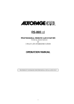
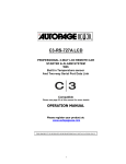
RF-520LCD
2-WAY AM/AM LCD COMMUNICATION
PROFESSIONAL VEHICLE SECURITY SYSTEM
OPERATIONS MANUAL
TABLE OF CONTENTS
Introduction
Changing Battery XT-72S Standard Transmitter
Remote Transmitter Operation
LCD Transmitter Operation
Button Lock LCD Transmitter
LED Display
Chirp Indicators
Parking Light Flashes
Alarm Operation Condition
Active Arming
Ajar Warning
Silent Arming
Shock Sensor By-pass
Hidden Alarm
Passive Arming
Passive Arming By-pass
Active Disarming
Tamper Disarming
Pathway Illumination
2 Step Unlock
Automatic Rearm
Disarm without Transmitter
Valet
Enter & Exit Valet Mode
Car Locator
Panic Function
Trigger the System
System Status check
Driver Paging
Dome Light Supervision
Ignition Control Door Locks
Trunk Release Output
Channel 3 Auxiliary Control
Channel 4 Auxiliary Control
Channel 5 Auxiliary Control
Channel 6 Auxiliary Control
Second Vehicle Operation
LCD Remote Control
LCD Battery Replacement
LCD Icons
Programming LCD Transmitter
Timer Setting
Autopage Warranty
2
3
3
4
5
5
5
5
5
6
6
6
6
6
6
7
7
7
7
7
8
8
8
8
8
8
8
9
10
10
10
10
10
10
10
11
11
11
12
12
12
13
15
17
Congratulations on your purchase of the RF520LCD vehicle security system. We
sincerely hope the purchase of the RF520 security system gives peace of mind to
you.
The RF520 LCD is a state-of-the-art two-way communication system. Please take
the time to read over this manual to thoroughly familiarize your self with the many
features and options of the RF520.
Auto Page, Inc. has over 25 years of experience in the vehicle security industry in the
United States and is a wholly owned subsidiary of Iwata Electric Co., of Tokyo, Japan.
Iwata has been an industry leader for over 50 years, establishing a reputation for
ingenuity in its engineering capability and innovative communication products. Auto
Page and Iwata maintain a long tradition of providing the best value to their
customers.
TRANSMITTERS
The RF520 comes with two transmitters. The XT72LCD is a 2-way transmitter and
receiver, also referred to as a transceiver. The XT72s is a mini-size 1-way
transmitter. Both operate on the AM band with a code-rolling feature that will prevent
any illegal use of a code-grabber attempting to record and steal the codes of your
transmitter.
CHANGING THE BATTERY IN YOUR TRANSMITTERS
XT72LCD: This transmitter uses a standard 1.5-volt AAA battery. Information on
changing the battery can be found on page 12 of this manual.
XT72S: This transmitter uses two (2) 3-volt lithium ion batteries (#CR2016) that are
sandwiched together with the (+) side facing upward. To replace the battery, you will
need to use a small flat blade screwdriver. Locate the small notch on the lower right
side of the transmitter case next to the key ring. Using the flat blade screwdriver,
carefully pry the top case from the bottom case. It should snap apart after breaking
the seal. Before removing the batteries note the direction of the positive (+) terminal.
Place the new batteries in exactly the same manner, being careful not to bend or
damage the contact terminal. Snap the cases back together and then test the
transmitter to insure it arms and disarms the alarm.
XT-72S
(2) CR2016
3-Volt Batteries
3
WARNINGS:
As with any product that performs automatic functions, there are certain safety
precautions that you must
practice and be aware of.
1. Keep the transmitter out of children’s reach.
2. Do not leave anyone in the vehicle while running on remote control.
3. Alert servicing personnel that the vehicle can be started automatically.
4. Do not start the vehicle by remote while it’s in an enclosed area or garage.
5. Always apply the parking brake and lock the vehicle as you exit the vehicle.
6. The vehicle windows must be rolled up.
7. Should the unit malfunction, disconnect the fuse until the problem is corrected.
8. The use and operations of this system is the sole responsibility of the operator.
9. Some areas may have local ordinances that prohibit leaving a vehicle running on
public streets.
10. Do not start the vehicle by remote while the standard transmission vehicle is
parked at a steep place
OPERATION:
REMOTE TRANSMITTER OPERATION:
Transmitter
Button
System Function
Remark
Lock Doors & Arm System
+
-
Panic function
Press and Hold for 3 seconds.
Car Locator
Arm and Delete The 2 Stage Shock
Sensor.
Silent Arming / Disarming
Under armed mode
Arm System and Hidden Alarm
Press twice within 3 seconds.
Press twice within 3 seconds
Ignition in "off" position.
Unlock Doors & Disarm System
-
Two Steps Door Unlock & Disarm
Press twice within 3 seconds.
Trunk Release (Channel 2)
Press and Hold for 2 seconds
Passive Arming By-pass
While the system Disarmed.
Channel # 3 Auxiliary Output
+
Channel # 4 Auxiliary Output (4)
+
Channel # 5 Auxiliary Output (5)
+
Channel # 6 Auxiliary Output (6)
II.
Shifting Code for 2nd Car Operation
4
Standard Transmitter ONLY
LCD DISPLAY TRANSMITTER OPERATION ONLY:
Transmitter Button
-
(C)
-
-
(C)
(1 second)
-
Remark
System’s Trigger Check
Press within 3 seconds
System’s Status Check
Press within 3 seconds
LCD screen lamp turns on
+
System Function
(2 sec)
for 5 seconds.
Clear the Flash Icon and
Melody Sound on the LCD
Screen Transmitter
Switching code for 2nd / 1st
Car Operation
Press and hold for 1 second
Press within 3 seconds
Press within 3 seconds
BUTTON LOCK:
It is useful if you want to disable the transmission function of the LCD remote control
to temporarily prevent from any inadvertent pressing of buttons by others.
The 2-way remote control transmitter:
Press the
button first, within 3 seconds press and
hold the
( ) button for 2 seconds to activate or cancel
the button lock function.
The
icon will be displayed on the LCD screen to
confirm that the LCD remote transmitter is in the “Button
Lock” mode.
LED display:
LED
Off
Slow Flash
Fast Flash
On (Solid)
Function
Disarmed
Armed
Passive Arming
Valet Mode
CHIRP INDICATORS:
Chirp
1 chirp
2 chirps
3 chirps
4 chirps
6 chirps
Function
Arm
Disarm
Defective Reminder
Disarm / Triggered
Car Locator
LED
2 flashes... pause
3 flashes... pause
4 flashes... pause
5 flashes... pause
Function
Zone 1 / Warn-Away Trigger
Zone 2 / Trigger on Trunk/Hood
Zone 3 / Trigger on Door Switch
Zone 4 / Trigger on Shock Sensor
Zone 5 / Trigger on Ignition Switch
PARKING LIGHT:
Parking light
1 flash
2 flashes
3 flashes
12 flashes
5
Function
Arm
Disarm
Disarm / Triggered
Car Locator
ALARM OPERATING CONDITION:
Siren /
Horn
1 or 3
Chirps
2 or 4
Chirps
Parking
Light
LED
Doors
Starter
1 Flash
Slow
Flash
Locking
Disable
3. Trigger
Alarming
Flashes
4. Panic
Alarming
Flashes
5. Car Locator
6 Chirps
12 Flashes
1. Arming
2. Disarming
2 or 3
Flashes
Unlocking
Slow
Flash
Dome Light
Turns on for 30 -sec
Disable
Flashes
Flashes
Locking
ACTIVE ARMING – LOCK & ARM:
1.
2.
Press
button on the transmitter.
The siren will chirp once and parking light will flash once indicating that the
system is now armed. The vehicle door will lock upon arming when interfaced
with the security system.
System Arm
Door Ajar
Trunk / Hood Ajar
Clear The Flashing Icon:
Press the
button
3 times within 3 seconds
will clear the flash icon
on the LCD screen
transmitter.
AJAR WARNING: If the siren sounds 3 chirps, then you have left a door, or (optional)
trunk, and or hood lid ajar.
SILENT ARMING / DISARMING: Press the transmitter
and buttons at the same
time will arm or disarm your security system, No chirp sound will be heard, arm /
disarm confirmation will be through the vehicles parking lights only.
SHOCK SENSOR BY-PASS: Press the button on the transmitter two times within
3 seconds will arm the security system and by-pass the shock sensor. The system
will chirp one additional time to confirm the sensor bypass mode was activated. The
sensor bypass feature is programmed to activate for one arming cycle only. The
security system will return to normal operation during the next arming cycle.
HIDDEN ALARM FUNCTION: Press the
button first; within 3 seconds press the
button to activate the hidden alarm function. The security system will arm and with
“Hidden Alarm Function”. The siren / horn will be silenced even if the sensor is
triggered in the armed status.
6
PASSIVE ARMING
Active arming / disarming is controlling your security system via the remote
transmitter. This security system is equipped with an optional Passive Arming feature,
which allows the security system to arm 30 seconds after the last door is closed.
Operation is as follows.
1. Turn the ignition to the “OFF” position and exit the vehicle.
2. After all entrances are closed, the security system LED will flash fast for 30
seconds. If you reopen any door / hood / trunk, the security system LED will stop
flashing. It will begin flashing again once the vehicle all entrances are closed.
3. After 30-second timer has elapsed, the security system will automatically “ARM”.
The siren will chirp [1] time and the parking lights will flash [1] time.
PASSIVE ARMING WITH PASSIVE DOOR LOCKING:
The vehicle doors will automatically lock after passive arming cycle has been
completed.
PASSIVE ARMING BY-PASS: While the system disarmed, Press the
button
twice, the security will respond with [1] chirp and LED will turn “ON”. The security
system will remain in this temporally state for as long as you wish. To exit passive
by-pass, press the transmitter
or
button and the system will return to normal
status.
ACTIVE DISARMING – UNLOCK & DISARM:
Press button on the transmitter.
The siren will chirp twice and parking light flash twice to indicating that the security
system is now disarmed. The vehicle’s door will unlock and dome light turns on for
30 seconds upon disarming when interfaced with the security system.
System Disarm
Doors Trigger
Trunk/HoodTrgr
Shock SensorTrgr
Ignition
Trigger
Clear The Flash Icon:
Press the
button 3
times within 3 seconds will
clear the flash icon on the
LCD screen transmitter.
TAMPER DISARMING: If alarm triggered, upon disarm the system, siren chirp 4
times, parking light flash 3 times.
PATHWAY ILLUMINATION: This feature turns the parking light “ON” for 30 seconds
upon a unlock signal and for 10 seconds upon the lock s ignal.
7
TWO STEPS DOOR UNLOCK: This feature will independently unlock the driver’s
door only when disarming the security system. Pushing the
button a second time
within 3 seconds will unlock the other doors.
AUTOMATIC RE-ARM : If this feature is selected, the security system will
automatically re-arm itself in 60 seconds after disarming with remote transmitter.
Automatic rearm will cancel if any door is opened before the 60 seconds timer has
elapsed.
DISARMING WITHOUT A TRANSMITTER
The Override function may be used if the remote transmitter is lost or inoperative.
1. Enter the vehicle and turn the ignition switch to 'ON’ position. (Alarm will sound.)
2. Within 10 seconds press the valet switch.
The alarm will stop sounding and enter the disarm mode, release the valet switch.
You can now start and operate the vehicle normally.
VALET MODE: (System in Disarm or Valet mode)
The valet switch allows you to temporarily bypass all alarm function, eliminating the
need to hand your transmitter to parking attendants or garage mechanics. When the
system is in valet mode, all alarm function are bypassed, however the remote panic
feature and remote door locks will remain operational. To use the valet mode, the
system must first be disarmed either by using you remote transmitter, or by operating
the Manual override sequence.
Enter Valet Mode:
1. From the disarmed condition, turn the ignition
to “ON” position.
2. Push and hold valet switch for 3-5 seconds
until the LED turns on. The LED will remain on as
long as the system is in 'valet mode'.
Exit Valet Mode:
1. Return to normal operation, turn ignition 'on'
Remote Door Lock
2. Push and hold valet switch for 3-5 seconds, The LED
will turn off indicate the system are exiting the valet mode.
CAR LOCATOR
Upon armed, press the
button to active car locator
function. The siren will chirp 6 times. The parking light
will flash 12 times, for you to easily locate your car.
PANIC FUNCTION:
The transmitter can be used as a remote panic switch to manually
trigger the alarm in case emergency.
1. Press and hold the
button for 3 second. The alarm will
immediately sound.
2. To stop the alarm, press
or
button, the panic mode will be
turned off immediately.
3. If the button is not pressed, the alarm will automatically stop
after 30 seconds.
8
Remote Door Unlock
TRIGGER THE SYSTEM
When armed, your vehicle is protected as follows:
1. Light impact will trigger the warn-away signal.
2. Heavy impacts / Doors open / Hood open / Trunk open / Turn on the ignition key
will trigger the programmed sequence.
The starter disable relay (if installed) prevents the vehicle’s starter from cranking. The
siren, horn, parking lights, and dome light will turn on to alerting of an intrusion for 30
seconds. Then it will stop and automatic reset and re-arm. If the one of sensors or
detectors still active, the alarm system will sound a maximum of 3 times of 30
second cycles.
Trunk/Hood Trigger
Doors Trigger
Shock Sensor Trigger
Ignition Trigger
Warn-away Trigger CLEAR THE FLASH ICON AND MELODY SOUND: While triggering
the alarm the LCD screen will alert user through melody sound and
flashing trigger icon, press the
button 3 times within 3 seconds
will clear the flash icon and stop melody sound on the LCD screen
transceiver.
STOP THE MELODY SOUND ONLY: While triggering the alarm the
LCD screen will alert user through melody sound and flashing trigger
icon, press any button on the LCD remote transceiver to stop melody
sound only
NOISE ABATEMENT CIRCUIT: Your system has “Noise Abatement Circuit”. It
prevents annoying repetitive trigger sequences due to faulty door pin switches or
environmental condition such as thunder, jackhammers airport noise, etc.
Here’s how “Noise Abatement Circuit” works: The alarm triggers five times. Each
time, the same sensor or switch is triggering the alarm. “Noise Abatement Circuit” will
interpret this pattern of triggers as false alarm. After the third trigger, “Noise
Abatement Circuit” ignores, or bypasses, that sensor or switch until the other sensor
or switch is trigger. “Noise Abatement Circuit” covers doors (Hood/Trunk) differently: If
the alarm is triggered by an open door for three full cycles, the doors will be bypassed
until the trigger ceases.
SYSTEM’S TRIGGER CHECK
(For two-way transceiver operation only)
Press the transceiver
button first, within 3 seconds press the
(C) button. It responds with one melody sound and all
trigger’s records will immediately displayed on the LCD screen.
Note: If it has no responds then you are out of range.
9
SYSTEM’S STATUS CHECK
(For two-way transceiver operation only)
When you want to check the system’s present status through the
LCD screen, Press the transceiver
button twice, within 3
seconds press
(C) button. It responds with one melody sound,
the LCD screen should be illuminated.
Note: If it has no responds then you are out of range.
DRIVER PAGING
(For two-way transceiver operation only)
It is useful the event that someone wants to page the driver of the
parked vehicle.
Under the ignition switch “off” condition, press and hold the valet
switch for 2 seconds or press the pager button once on the
transmitter antenna to page the driver, one chirp sound shall be
emitted from the vehicle and the paging melody sound continues
you Remote LCD transceiver and “
LCD screen.
” indication flashes on the
DOME LIGHT CONVENIENCE DELAY & SUPERVISION
The alarm with a unique feature which will turn on your vehicle dome light as
following:
1. Upon disarming, the interior light will remain on for 30 seconds.
2. If the vehicle is intruded, the dome light will flash for the same duration as the siren.
Note: Turn on the ignition switch or arm the alarm will turn off the dome light.
IGNITION CONTROL DOOR LOCK/UNLOCK.
If the vehicles door locks have been interfaced to the security system, the system will
automatically lock the vehicle's doors when the ignition is turned “ON” and /or unlock
the vehicle’s doors when the ignition is turned “OFF”.
TRUNK RELEASE OUTPUT.
Press and hold
button on the transmitter for 2 seconds to
remote control the trunk release or other electric devices.
CHANNEL 3 AUXILIARY CONTROL OUTPUT (Available Option)
Press the transmitter
button to active Channel 3 function. Channel 3 is a
programmable output. This feature, when installed with optional accessories, may be
used to operate power windows, sunroofs, etc. from your remote transmitter.
CHANNEL 4 AUXILIARY CONTROL OUTPUT (Available Option)
Press the transmitter
+
button to active Channel 4 function. Channel 4 is a
programmable output. This feature, when installed with optional accessories, may be
used to operate power windows, sunroofs, etc. from your remote transmitter.
10
CHANNEL 5 AUXILIARY CONTROL OUTPUT (Available Option)
Press the transmitter +
button to active Channel 5 function. Channel 5 is a
programmable output. This feature, when installed with optional accessories, may be
used to operate power windows, sunroofs, etc. from your remote transmitter.
CHANNEL 6 AUXILIARY CONTROL OUTPUT (Available Option)
Press the transmitter
+
button to active Channel 6 function. Channel 6 is a
programmable output. This feature, when installed with optional accessories, may be
used to operate power windows, sunroofs, etc. from your remote transmitter.
POWER ON MEMORY:
This security system is equipped with circuitry that will allow the unit to remember its
alarm state if the power is lost and then reconnected.
SECOND VEHICLE SECURITY OPERATION:
Your 5-button remote transmitter can be utilized to control a second vehicle security
system, To program the remote control transmitter to a second vehicle, follow the
instructions for Transmitter programming. All programming parameters be the same
except for the following:
For Regular Remote Control Transmitter:
1. Prior to pushing any button on the transmitter. Press the Select II button first on the
transmitter.
2. Once II button is pressed the LED on the transmitter will illuminate for 3.5 seconds
to indicate the second transmitter pin code has built-in.
3. While the LED is illuminated, press any button on the remote control transmitter to
control a second vehicle security system.
For 2-way LCD Remote Control Trans ceiver 2nd Car Operation:
1. Press
first, within 3 seconds press and hold
and
buttons at the same
time for 2 seconds with two beeping sound and the “
” icon will display on the
LCD screen to indicate the second transceiver pin code has built-in.
2. While the “
” icon display on the LCD screen, you can
remote control and communicate with a second vehicle security
system . It has two short “bi” sounds while pressing the button of
the LCD screen transceiver.
Back to 1st Car Operation:
1. Press
first, within 3 seconds press and hold
and
buttons at the same time for 2 seconds with one long beeping sound
and the “
” timer icon will display on the LCD screen to indicate the
system is back to first transceiver pin code.
2. While the “
” timer icon display on the LCD screen, you can
remote control and communicate with a first vehicle security system. It has
one short “bi” sound while pressing the button of the LCD screen
transceiver.
11
LCD REMOTE CONTROL TRANSCEIVER:
Note: If the system is interfered by stronger radio
frequency around, sources of high voltage
electric power or such Obstacles like tall
buildings and so on, the transmission range
may get shorter as the system uses low out
put powered frequency.
BATTERY REPLACEMENT:
A 1.5V type AAA Alkaline battery powers the Remote
Transmitter. When the power of the battery weakens a
icon shall be displayed on the LCD screen. When
the old battery is replaced to new one, there will be beep
sounds indicate the power is up and the clock on the LCD
screen returns to AM12:00 after displaying all the icons.
Correct the time by pressing
for 3 seconds before
using (See Timer Setting).
Note: Press the button two times when the battery compartment is empty,
and then insert the new battery.
THE REMORE LCD ICONS WITH FUNCTION:
Door Lock
Your vehicle doors
are locked
Armed Mode
Your vehicle is
in armed mode
Door Unlock
Your vehicle doors are
unlocked and the system is
Disarmed
Valet Mode
All the function shall be
temporarily on hold.
Remote Transmission
You are transmitting the
signal to control unit
In – Range Indicator
Your are within the remote
control range.
12
Door Open Warning
Doors are illegally opened
(Zone 3)
Trunk/Hood Trigger
Trunk or Hood is illegally
opened (Zone 2)
Shock Sensor Trigger
Trigger on Shock Sensor
(Zone 4)
Warn Away trigger
Trigger on Shock Sensor
(Zone 1)
Alert Alarm
You have set morning call
alarm
Power Save Mode
Save the battery power
Time Monitor
Count Down Timer
Reminder when time is up
for parking
Vibration Mode
Remote Control vibrates
when the system is
triggered
Driver paging
Someone is paging you in
front of your vehicle
Button Lock
Disable the transmission
function temporarily
Low Battery
You have to replace the
battery of remote control.
PROGRAMMING OF THE LCD REMOTE TRANSMITTER:
Transmitter Button
Description
Operation
LCD screen lamp turns on for Press and hold for 1 second
(1 second)
5 seconds.
1 melody sound to confirm
enters.
Timer Programming Mode.
Press and hold for 3 seconds
(3 seconds)
2-melody sounds to confirm
enter.
Power Save Mode
Press and hold for 5 seconds
(5 seconds)
1 melody sound to confirm
enters.
Clear the Flash Icon and Melody Press within 3 seconds
Sound on the LCD Screen
Transmitter
Press within 3 seconds
(2-second)
Button Lock ( ) enable / disable
-
(2-second)
Melody / Vibration (
) Mode
-
(2-second)
Program Count Down Timer ( )
(10-Minute / 20M / 30 M /1Hour
/1.5H / 2.0H)
-
(2-second)
Enable / Disable Bi Sound (Bi)
While Pressing Button
Press within 3 seconds
Press within 3 seconds
cycling
*leave the buttons starting
count
down then
13
flashes
Screen Lamp ON: Press and hold the
button one second, with
one melody sound and the LCD screen lamp will turns on for 5 sec.
Power Save Mode: While the power save mode, the LCD remote
transceiver uses “0” current to save the battery power.
Entry: Press & hold the
button for 5 seconds, with one melody
sound and
icon on the LCD screen to indicate entry the
“power save mode”.
Exit: Press any button of the LCD remote transmitter to exit the
“Power Save Mode”.
Clear the Flash Icon and Melody Sound: Press the
button 3 times within 3
seconds will clear the flash icon and melody sound on the LCD screen transceiver
Stop The Trigger Melody Sound: While triggering the alarm the LCD screen will
alert user through melody sound and flashing trigger icon, press any button on the
LCD remote transmitter to stop melody sound only.
Button Lock: It is useful if you want to disable the transmission
function of the remote control temporarily to prevent from any
inadvertent pressing of buttons by others. Press the
button first,
within 3 seconds press and hold the
( ) button for 2 seconds to
activate or cancel the button lock function, the icon will displayed
on the LCD screen to show the LCD remote transmitter is on “Button
Lock”.
Vibration / Melody Mode:
It is useful when you are in a noisy place and difficult to hear beep
sound from the remote control as the remote control in this mode,
vibrates itself if your security system is triggered.
Press the
button first, within 3 seconds press and hold the
(
) button for 2 seconds to select the mode of vibration or melody,
the
icon will displayed on the LCD screen to show the LCD
remote transceiver is on vibration mode.
Enable / Disable Bi Sound While Pressing Button:
It has a short “bi” sound while pressing the button of the LCD screen transceiver
If you want mute the “bi” sound mute always while press button. Press the
button
first, within 3 seconds press and hold the
(Bi) button for 2 seconds to disable the
“bi” sound.
Low Battery Indication:
When the power of the battery weakens, it has two short “bi” sound and flash
icon while pressing the button of the LCD screen transceiver.
14
Set Up Fixed Count Down Timer:
1. Press the
button first, within 3 seconds press and hold the
two seconds, the LCD screen will shows
(
) button for
icon and timer (ie. 0:10),
2. Press the
( ) button again showing next order time on the screen ( ie.0:20),
press them again (ie.0:30)…..and so on.
3. Leave the buttons starting count down then
icon flashes
Note:
1. The count down period is fixed as 10 minutes, 20 minutes, 30 minutes, 1 hour, 1.5
hours and 2 hours maximum.
2. When count down timer showing 0:00 means to turn off the timer.
3. Press
button for real time indication when the timer is counting down.
Out Of Range Indication:
The system will automatically check the range every 20 minutes after armed.
1. If user is within the range, the
icon will display on the LCD screen.
2. If user is out of range, it has five short “bi” sounds and the
on the LCD screen.
TIMER SETTING:
Transceiver
Button
Press & Hold the
1
button for 3
seconds
Press the
button once
2 Press the
button once.
Press the
button once
Press the
button once
Description
icon will disappear
Press Transceiver Button
Timer Setting (Hour)
*Flash digit for adjusting
Time setting (Minute)
*Flash digit for adjusting
Alert Alarm Time Setting (Hour)
*Flash digit for adjusting
Alert Alarm Time Setting (Minute)
*Flash digit for adjusting
Alert Alarm Setting ON / OFF
for – and
for +
for – and
for +
for – and
for +
for – and
for +
for OFF and
for ON
Count Down Timer Setting (Hour)
*Flash digit for adjusting
for – and
for +
(Max.19 hours 59 minutes)
Count down Timer Setting (Minute)
Press the
for – and
for +
button once
*Flash digit for adjusting
Count down Timer Setting ON /
Press the
for OFF and
for ON
OFF
button once
EXIT: Press and hold the
button for 2 seconds or leave it for 10seconds, the
system will exit the programming mode.
3
Press the
button once
15
Timer Setting: Example to AM10:30
1. Press & hold the
button for 3 seconds, with two-melody sound and the
“Hours” digit flashes for adjusting.
2. Press the
or
button to decrease or increase the “Hour” digit until AM10: xx
3. Press the
button once again then the “Minute” digit flashes for adjusting.
4. Press the
or
button to decrease or increase the “Minutes” digit until AM
10:30
5. Press the
button for 2 seconds with one-melody sound to confirm exit the
timer program mode.
Alert Alarm Timer Setting: Example to PM 6:30
1. Press & hold the
button for 3 seconds, with two-melody sound and the
“Hours” digit flashes for adjusting.
2.
3.
4.
5.
Press the
button twice, the LCD screen will shows
icon and “Hours” digit
is flashes for adjusting.
Press the
or
button to decrease or increase the “Hour” digit until PM 6:xx
Press the
button once again then the “Minutes” digit flashes for adjusting.
Press the
or
button to decrease or increase the “Minutes” digit until PM
6:30
6.
Press the
button once again then
icon flashes for alert alarm “ON / OFF”
setting
7. Press the
button to start the “Alert Alarm Timer”, and the “ON” icon will show
on the LCD screen. Press the
button to stop the “Alert Alarm Timer”, and the
“OFF” icon will show on the LCD screen.
8. Press
button for 2 seconds with one-melody sound to confirm exit the timer
program mode.
Count Down Timer Setting: Example Set count down timer at 2:30
1. Press & hold the
button for 3 seconds, with two-melody sound and the
“Hours” digit flashes for adjusting.
2.
3.
4.
5.
Press the
button 5 times, the LCD screen will shows
icon and “Hours”
digit is flashes for adjusting.
Press the
or
button to decrease or increase the “Hour” digit until 2:xx
Press the
button once again then the “Minutes” digit flashes for adjusting.
Press the
or
button to decrease or increase the “Minute” digit until 2:30
6.
Press the
button once again then
icon flashes for alert alarm “ON /
OFF” setting
7. Press the
button to start the count down timer, and the “ON” icon will show on
the LCD screen.
Press the
button to stop the count down timer, and the “OFF” icon will show
on the LCD screen.
8. Press the
button for 2 seconds with one-melody sound to confirm exit the
timer program mode.
Note: Maximum is 19 hours.
16
LIMITED LIFETIME WARRANTY PROVISIONS
( U.S. and Continental U.S. Only)
1.
AutoPage, Inc. WARRANTS that this new unit has been thoroughly inspected and tested at the
factory prior to delivery. Your AutoPage equipment is guaranteed for “life” to the original
purchaser/user of the equipment under the following conditions: If the product proves defective
(according to AutoPage’s testing) within the first year, the defective unit may be exchanged or
repaired free of charge. “Proof of Purchase” (dated sales receipt) must accompany all warranty
returns; otherwise, your return will be rejected and sent back. After one (1) year, the purchaser
should ship the unit prepaid to AutoPage with a money order in the amount of $20.00 to cover
shipping and handling charges. Note: The enclosed Warranty Card may be required to receive
warranty services.
2.
This WARRANTY will be considered void if the equipment has been misused, neglected,
improperly serviced, altered, dropped or damaged by water, contrary to the AutoPage
OPERATIONS MANUAL. Or, if used with accessories not approved by AutoPage, which may
have contributed to the defect.
IMPORTANT NOTE: Any damages to the alarm system resulting from an
installation performed by anyone other than a professional installation
technician authorized by a dealer of Auto Page will void the product’s warranty.
3.
The purchaser’s remedies under this WARRANTY shall be limited to the repair or replacement of
electronic components only. THE FOLLOWING IS NOT COVERED: Damages or deterioration
to cases, batteries, covers and cabinets; the cost of repairs, replacement and labor of which shall be
borne by the purchaser even if occurring during the WARRANTY period.
4.
Any equipment or parts which are claimed to be defective under this WARRANTY must be sent to
the AutoPage Service center wit h “proof of purchase” at the purchaser’s expense prior to such
return, a Return Authorization Number should be obtained. AutoPage will return the equipment,
charges prepaid. Warranty Service can be provided through the dealer where the equipment is
originally purchased.
5.
Any unexpired WARRANTY shall be applicable to equipment and parts in the possession of the
original purchaser only.
6.
THIS WARRANTY IS IN LIEU OF ANY AND ALL OTHER WARRANTIES, EXPRESSED OR
IMPLIED, INCLUDING BUT NOT LIMITED TO ANY WARRANT Y OF MERCHANTABILITY
OR FITNESS FOR A PARTICULAR PURPOSE.
7.
AutoPage shall not be liable, under the foregoing WARRANTIES or otherwise, for: Any personal
injury of any kind to the purchaser, its employees or agents or anyone else whomsoever resulting
direct ly or indirectly from the use or presence of the equipment or parts; Consequential damages of
any kind; any inability of the purchaser to use the equipment.
17
This WARRANTY CARD is for your record. However, AutoPage reserves the right to
request you to submit this WARRANTY CARD, which must have complete information to
receive warranty service. Please keep this card in a secured place .
AUTOPAGE WARRANTY SERVICE CARD
Model:
______________
Serial # _______________
CUSTOMER TO COMPLETE
DEALER TO COMPLETE
Mr./Mrs./Ms.
___________________________ ________________________________
Your Name (Please Print)
Company Name
___________________________ ________________________________
Address
Dealer’s Address
___________________________ ________________________________
City, State, Zip Code
City, State, Zip Code
___________________________ ________________________________
Telephone Number
Dealer’s Telephone Number
___________________________ ________________________________
Year / Make / Model of Vehicle
Date of Installation / Purchase
________________________________
Dealer’s Signature
“Proof of Purchase” which includes the store name and date of purchase must
accompany all warranty returns.
It is the purchaser’s responsibility to keep this card for any future warranty service.
18
1815 West 205th Street Suite 101
Torrance, California 90501-1525
Main Office: 310-618-2002
Customer Service: 800-262-2527 Ext. 462
www.autopageusa.com
19