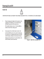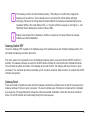
1
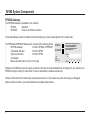
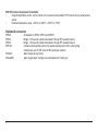
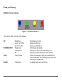
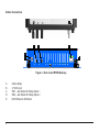
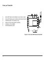
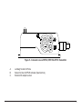
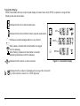
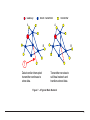
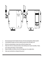
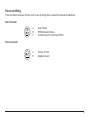
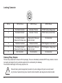
RF500A Gateway System Manual Contents RF500 System Components.............................................................................................................................................4 RF500A Gateway.................................................................................................................................................4 RF500 Transmitters.............................................................................................................................................5 RF512 Temperature Transmitter.............................................................................................................5 RF512M Temperature Transmitter Backbone Option..............................................................................5 RF513 Temperature and Humidity Transmitter........................................................................................5 RF513M Temperature and Humidity Transmitter Backbone Option........................................................5 RF515 Analog Input Transmitter and RF515A Connection Box..............................................................5 RF516 Precision Temperature Transmitter..............................................................................................6 Optional Accessories...........................................................................................................................................6 Know your Gateway.............................................................................................................................................7 RF500A Front Panel Indicators...............................................................................................................7 Bottom Connections................................................................................................................................8 Alarm Outputs.........................................................................................................................................9 Side Switches and Indicators..................................................................................................................9 Know your Transmitter.......................................................................................................................................10 Transmitter Display................................................................................................................................12 Safety Information...........................................................................................................................................................13 Warning..............................................................................................................................................................13 WEEE................................................................................................................................................................14 RF500 Wireless Monitoring System Overview................................................................................................................15 Gateway – Introduction......................................................................................................................................15 Overview of RF500 Mesh Networking................................................................................................................16 Meshing Transmitters and Backbone Transmitters............................................................................................18 Automatic Data Retrieval (ADR)........................................................................................................................18 1 Equipment Installation.....................................................................................................................................................19 Gateway Fixing..................................................................................................................................................19 Transmitter Fixing..............................................................................................................................................19 Mains Wiring......................................................................................................................................................19 Ventilation..........................................................................................................................................................19 Powering On and Off......................................................................................................................................................20 Switch On...........................................................................................................................................................20 Gateway Switch OFF.........................................................................................................................................21 Gateway Reset..................................................................................................................................................21 Transmitter Activation........................................................................................................................................22 RF500ACONFIG Utility...................................................................................................................................................23 Installation of USB Drivers..................................................................................................................................23 Obtain Comark USB Drivers..................................................................................................................23 USB Driver Installation Instructions.......................................................................................................24 Installation of RF500ACONFIG..........................................................................................................................25 Obtain RF500ACONFIG Utility...............................................................................................................25 RF500ACONFIG Installation Instructions..............................................................................................26 Gateway Commissioning................................................................................................................................................27 Requirements for Commissioning.......................................................................................................................27 Setting of Gateway IP Address using RF500ACONFIG.....................................................................................27 Viewing the Gateway Login Page......................................................................................................................29 Setup of First Administrator.................................................................................................................................30 Gateway Language............................................................................................................................................31 Gateway Name..................................................................................................................................................31 Gateway Clock Setup..........................................................................................................................................31 Network Setup...................................................................................................................................................32 Network Details.....................................................................................................................................32 Gateway Programming and Use.....................................................................................................................................33 Gateway Specification – RF500A...................................................................................................................................34 2 Transmitters Specification...............................................................................................................................................35 Changing Lithium Battery on RF500 Series Transmitters...............................................................................................38 Battery Reordering.............................................................................................................................................38 Battery Change Procedure.................................................................................................................................38 Check for Transmitter Errors...............................................................................................................................40 Gateway Indication of Low Battery......................................................................................................................40 Pinout and Wiring............................................................................................................................................................41 Door Connector..................................................................................................................................................41 Power Connector...............................................................................................................................................41 Lumberg Connector...........................................................................................................................................42 Gateway Relay Outputs.....................................................................................................................................42 FCC Approvals................................................................................................................................................................43 Equipment Ratings..........................................................................................................................................................44 Supply Voltage...................................................................................................................................................44 Environmental Conditions...................................................................................................................................44 Gateway Storage/Operating Conditions................................................................................................44 RF51X Transmitter Operating Conditions..............................................................................................44 RF51X Transmitter Storage Conditions.................................................................................................45 RF515 Maximum Input Conditions.....................................................................................................................45 Maintenance and Cleaning.............................................................................................................................................45 EC-Declaration of Conformity.........................................................................................................................................46 Transmitter Error Codes..................................................................................................................................................47 Gateway Fault Conditions...............................................................................................................................................47 Appendix A - Setting a Fixed IP Address.........................................................................................................................48 Appendix B – Gateway Connection via RJ45 Cross-Over Ethernet Cable.....................................................................50 Definitions of Gateway Terminology................................................................................................................................51 Glossary..........................................................................................................................................................................54 3 RF500 System Components RF500A Gateway The RF500A Gateway is available in two variants: • RF500A Standard • RF500AP Power over Ethernet enabled The actual Gateway model is indicated on the side label by a check mark adjacent to the model code. The RF500A and RF500AP Gateway Kit consists of the following items. • RF500A Gateway Part No. RF500A or RF500AP • Transmitter Activator Part No. RF525 • High Gain Antenna. Part No. RF504 • AC Adaptor • Mains Lead with either UK, EU or US plug RF500A RF500AP ON / OFF Comark Instruments, 52 Hurricane way, Norwich, Norfolk, NR6 6JB. UK Tel: 01603 (+44 1603) 256647 Email: [email protected] www.comarkltd.com Comark Instruments, Everett, WA 98206, US Tel: (503) 643 5204 Email: service@coma www.comarkUSA.com SERIAL No. FOR INDOOR USE O DO NOT MOVE WHE IN OPERATION STATUS 1 2 3 4 MADE IN UK Software and USB drivers are no longer provided on CD and can be downloaded free of charge from our website. See RF500A Configure Utility for instructions on how to download the software and drivers. Please confirm that the kit contents are all present and correct. If you believe any parts are missing or damaged please contact Comark or your local Distributor to arrange replacements. 4 RF500 Transmitters RF500 Transmitters are available as follows. Each RF500 Transmitter is packed with a mounting bracket and 2-tie- wraps. RF512 Temperature Transmitter • Integral temperature sensor plus connectors for two external temperature sensors and an external door sensor • External temperature range: –40°C to +125°C / -40°F to +257°F RF512M Temperature Transmitter Backbone Option • Integral temperature sensor plus connectors for two external temperature sensors and an external door sensor • External temperature range: –40°C to +125°C / -40°F to +257°F • Includes High Gain Antenna and RF520 AC mains adaptor RF513 Temperature and Humidity Transmitter • Integral temperature sensor, one integral humidity sensor and connector for an external door sensor • Integral temperature range: –30°C to +70°C / -22°F to +158°F • Humidity range: 10-90% RH RF513M Temperature and Humidity Transmitter Backbone Option • Integral temperature sensor, one integral humidity sensor and connector for an external door sensor • Integral temperature range: –30°C to +70°C / -22°F to +158°F • Humidity range: 10-90% RH • Includes High Gain Antenna and RF520 AC mains adaptor RF515 Analog Input Transmitter and RF515A Connection Box • Two analog input channels, each capable of configuration as 0-1V, 0-10V or 4-20mA using RF515A connection box 5 RF516 Precision Temperature Transmitter • Integral temperature sensor, and connector for one external temperature Pt100 sensor and an external door sensor • External temperature range: –200°C to +400°C / -328°F to +752°F Optional Accessories RF520 RF502 RF503 RF515A RFJACK RFALARM 6 AC adaptor for RF512, RF513 and RF516 Bridge. 0.5m lead to enable transmission through RF resistant barriers Bridge. 1.0m lead to enable transmission through RF resistant barriers 2-Channel Terminal Box with 0.25m lead terminated with 6-Pin Lumberg Plug Includes two sets of 10R, 2K and 18K2 precision resistors Alarm Output jack (2.5mm) Alarm Output lead. 2m fig-8 wire terminated with 2.5mm jack Know your Gateway RF500A Front Panel Indicators ON POWER / BATTERY FAULT ALARM Figure 1 - Front Panel Indicators There are four LEDs on the front of the Gateway: ON Steady Blue The Gateway is running ¼s on / ¼s off Blue Gateway is starting up 2s off / 2s on Blue Gateway is shutting down POWER/BATTERY Steady Green External power is available Flashing Green Gateway is on and running off the battery pack Off Gateway is off and external power is not available FAULT Flashing Yellow Contact technical support from your local distributor or Comark Instruments. The Home Page may provide more information on possible faults ALARMFlashing Red An enabled alarm event has occurred 7 Bottom Connections C D E B A Figure 2 - Rear view of RF500 Gateway A. B. C. D. E. 8 Cable clamps 12 VDC input SW1 - Jack Socket for Relay Output 1 SW2 - Jack Socket for Relay Output 2 RJ45 Ethernet LAN Socket A Alarm Outputs SW1 & SW2 are two switched outputs provided for connection to customer alarm indicators, via relay contacts with 24Vdc 500mA rating, configurable for either NO (Normally Open) or NC (Normally Closed). These are marked as SW1 and SW2, and are in the form of 2.5mm Jack Sockets. Plugs to fit these sockets can be ordered from Comark Instruments using part number: RFJACK. With the Gateway switched OFF the relays are in a Normally Open condition, this may cause any equipment connected to the contacts to energise. Side Switches and Indicators RF500A RF500AP ON / OFF Comark Instruments, 52 Hurricane way, Norwich, Norfolk, NR6 6JB. UK Tel: 01603 (+44 1603) 256647 Email: [email protected] www.comarkltd.com Comark Instruments, PO Box 9090, Everett, WA 98206, USA Tel: (503) 643 5204 Email: [email protected] www.comarkUSA.com SERIAL No. FOR INDOOR USE ONLY DO NOT MOVE WHEN IN OPERATION STATUS 1 2 3 4 MADE IN UK AUX Figure 3 – Left Hand Side View of Gateway ON/OFF Gateway Startup/Powerdown switch STATUS Diagnostic LEDs for technical support use AUXReserved Switch 9 Know your Transmitter A A. B. C. D. E. F. Alarm LED. Flashes red to indicate any one channel in alarm Active LED. Flashes green to indicate external power detected Infra-Red interface. For Comark use only Antenna. (Do not remove whilst in operation) Lashing eye - Four available Internal temperature sensor B C D E F Figure 4 - Front view of RF512 Series Transmitter 10 A B C Figure 5 - Connector view of RF512, RF515 & RF516 Transmitter A. B. C. Lumberg Socket for Probe Socket for Door & RF525 Activator (Dual function) External DC adaptor socket 11 Transmitter Display RF500 Transmitters all have a liquid crystal display as shown below. Only RF512 is capable of using all three display areas and annunciators. Indicates that the door channel reads open. Indicates that the internal lithium battery requires replacement. Indicates an unacknowledged alarm on any channel. When steady, indicates that the transmitter has logged onto the Gateway. When flashing, indicates the transmitter is currently attempting transmission with the Gateway. Indicates that the sensor or probe is broken. Indicates that the number to be displayed is too big to fit on the LCD E.g. 2000 cannot be shown on a “1999” digit area. 12 INT EXT1 EXT2 Figure 6 - Transmitter Display Safety Information Under no circumstances may a user make any changes to the RF500A Gateway that would alter its performance. Any modification would void the CE compliance of the Gateway and may invalidate the warranty. If the equipment is used in a manner not specified by Comark Instruments, then the protection provided by the equipment may be impaired. No user serviceable parts are provided in RF500 Comark Wireless Monitoring Equipment. Contact Comark Instruments or your local distributor for all service requirements. Warning • • • • • • Before connecting or disconnecting the antenna, ensure anti-static precautions are observed. Use only the FRIWO 12V AC adaptor; Type FW74010/12 as supplied; with the RF500A Gateway. Do not modify the RF500A Gateway AC adaptor in any way. Use only the PHIHONG, PSM11R-050 5V AC adaptor or FRIWO type FW7662/05 with RF500 Transmitters. It is supplied by Comark Instruments as three variants: RF520 Transmitter AC adaptor with UK plug RF520/EU Transmitter AC adaptor with European style plug RF520/US Transmitter AC adaptor with North American style plug Do not modify the AC adaptor in any way. RF500 Transmitters contain a C-size lithium cell. This cell must not be incinerated or subjected to temperatures in excess of 100°C / 212°F. Do not deform, mutilate, crush, pierce, disassemble, recharge or short circuit. Such abuse can result in loss of seal, and/or cell explosion. Also exposure to humid conditions for long periods should be avoided. 13 • Do not insert metal objects into connectors. • Ensure the antenna is securely connected before powering the equipment. Internal damage may result otherwise. • The Gateway and Transmitters have been designed to operate with the antenna supplied by Comark, and having a maximum gain of 7dBi. Antennas not supplied by Comark Instruments or having a gain of greater than 7dBi are strictly prohibited for use with this device. The required antenna impedance is 50 Ohms. If in doubt please contact Comark Instruments or your Distributor for advice. WEEE RF512, RF513, RF515 and RF516 Transmitters contain a non rechargeable lithium battery. This battery must be disposed of in accordance with local regulations. 14 RF500 Wireless Monitoring System Overview Gateway – Introduction The RF500A Gateway is an embedded microprocessor device containing a radio module for RF communications to the measuring transmitters. The radio module uses a licence free band in the 2.4GHz spectrum. Comark Instruments RF500 uses proprietary protocols over a standard IEEE 802.15.4 link. These protocols achieve reliable communication between the transmitters and the Gateway via self-healing mesh radio networks. Data from measurements taken by the transmitters is stored on the RF500A Gateway in contrast to other systems which store their data on a PC using special software. For operating the RF500 system the only software required is a Web Browser such as Internet Explorer or Firefox. There is no requirement to install software on each user’s computer. The Gateway contains sufficient data storage capacity for up to 10 years which can be automatically backed up to external storage using the built in shared drive backup method, or by manual request to generate and download a backup file via your web browser. An external power adaptor provides the mains power for the Gateway. An internal Nickel-Metal-Hydride (Ni-Mh) rechargeable battery is included, this provides normal operation of the Gateway during power failure until the battery is exhausted, The Gateway then shuts down until power is restored. Two relay connectors are provided for external alarms, Autodiallers/Klaxons etc. All other connections to the Gateway are disabled. See Figure 2 – Bottom View of Gateway for further details. Emails for alarms will be instigated directly from the Gateway. It is also possible to send a text message alarm via email using a third party provider. 15 The Gateway can be either desk mounted or wall mounted. Wall mount keyhole slots are provided on the case. The external long range Antenna has variable orientation to suit vertical or horizontal mounting. Four LEDs on the Gateway display current status of the system – On/Off, Power/Battery, Alarm indication, and Fault indicators. Overview of RF500 Mesh Networking The RF500 Wireless Monitoring System uses the IEEE 802.15.4 radio transmission standard to implement a radio mesh network. A mesh network is comprised of the following devices: • Gateway • Mesh Transmitter • Transmitter On installation each transmitter is associated with a particular Gateway by serial number. Messages are transferred between transmitters and the Gateway using two-way communication with acknowledgement of successful message reception. Transmitters which are physically close to their associated Gateway such as transmitter A in Figure 7 below, will most likely transmit directly to it. Others such as transmitter B which are further away rely on meshing transmitters to forward messages to and from the Gateway on their behalf. The route taken by the message can vary depending on network load and link reliability. The ability to dynamically reconfigure the network is termed self-healing. In the figure below the self-healing ability is shown. 16 Gateway Mesh Transmitter Transmitter A A B B ! Data transfer interrupted transmitter continues to store data. Transmitter reroutes to self-heal network and transfers stored data. Figure 7 - A Typical Mesh Network 17 Meshing Transmitters and Backbone Transmitters Whenever a RF512 or RF513 transmitter is powered by a RF520 AC adaptor it will become a Meshing unit and will form part of the radio mesh network. However if external power is removed it will revert back to a regular Transmitter. RF512 and RF513 have the option to become “Network Backbone” units or routers which will intelligently forward messages on behalf of other transmitters. This option is enabled using a setup option in the Gateway. Backbone Transmitters will form part of the mesh network continuously even when not powered by a RF520. Due to the very large drain on the internal battery, Backbone Transmitters must be powered using a RF520 mains adaptor. The internal battery is considered only as a backup battery for Backbone Transmitters. Automatic Data Retrieval (ADR) The fact that transmissions between Transmitters and the RF500 Gateway are acknowledged ensures that the Transmitters know exactly which data records have been successfully transferred to the Gateway and those which must be re-transmitted. Therefore if the Gateway is temporarily unable to receive or transmit messages for whatever reason, data will not be lost during this period. When the Gateway is again able to receive and transmit properly the Transmitters will re-transmit those records which were unable to be transmitted during the period of outage. This re-transmission of data happens automatically without user intervention and results in seamless graphical and tabular data with no gaps. 18 Equipment Installation Comark Instruments strongly recommend that RF500 System installation is carried out by a Comark Installation Engineer or by a Comark Authorised Distributor or Agent. Gateway Fixing Mounting of the Gateway is possible using the keyhole screw fixings provided on the rear of the Gateway itself. However the fixings used are to be determined by the installation engineer depending on the type of material used in the construction of the area where the Gateway is to be placed. To avoid accidental disconnection, the DC power cable and cables connecting to the Relay Outputs should be secured using the cable clamps provided on the Gateway case. See Figure 2 - Bottom view of RF500A Gateway. Positioning of the Gateway should be in such a way as to limit the risk of liquid being spilt on it as damage may result. Transmitter Fixing Mounting of the Transmitters is possible using the mounting bracket provided. The bracket is fixed using 2 screws and the Transmitter then slides into the bracket from the top. With each Transmitter, Comark Instruments provide two cable ties which, once the Transmitter is slid into the bracket, can be fed through the slots in both bracket and Transmitter case to retain it. The door and DC power cables should be tie-wrapped to the bracket to avoid accidental disconnection. Mains Wiring Connections to mains supply for the Gateway and powered Transmitters is via the AC mains adaptors supplied and a locally installed socket. Any power requirements for the hardware will be determined during survey and should be installed by qualified electrician and certified as safe to use before installation can be started. Ventilation At no time should the ventilation slots on the Gateway be covered or obstructed. At least 100mm of free space must be provided above and below the Gateway to ensure that sufficient airflow is maintained through the case to provide adequate cooling. Failure to do this may result in damage to the Gateway due to overheating and invalidation of the warranty. 19 Powering On and Off Switch On BEFORE SWITCHING ON, ENSURE THE ANTENNA HAS BEEN FITTED - IT IS ESSENTIAL TO AVOID DAMAGE. 1. Plug the Gateway AC adaptor into the socket on the underside of the Gateway, or for the PoE model (RF500AP) plug the ethernet cable into a PoE enabled network socket . The Power/Battery indicator should show steady green. 2. Using a paper clip or similar object, press in and hold the ON/OFF switch on the side of the Gateway for 4 seconds. The Gateway will beep once and the On/Off indicator will flash at a half-second interval. Gateway bootup will begin. On successful boot, the On/Off indicator will show solid blue. 20 Figure 8 - Switch On using Paper Clip The Gateway contains an internal backup battery, if this battery is not sufficiently charged, the Gateway will not switch on. Once external power is connected the internal battery will begin recharging. Whenever the charge state becomes sufficient the Gateway will automatically start as requested. Whilst in this mode Status LEDs 1, 2, 3 and 4 will flash in sequence. See Figure 3 – Left Hand Side View of Gateway for location of these LEDs. It takes a few minutes for the Gateway to initialise. A sequence of 2 beeps followed by 4 beeps indicates successful initialisation. Gateway Switch OFF To turn the Gateway OFF navigate to the hardware page of the website and use the Shutdown Gateway button, this will initiate the Gateway shut-down procedure. If for some reason it is not possible to use the Shutdown Gateway button, press and hold the ON/OFF switch for 4 seconds. The Gateway will beep once and the On/Off indicator will flash at 4 second interval to indicate shut-down. This will initiate an orderly shut-down of the Gateway at the start of which, the Gateway will beep 10 times in quick succession. The shut-down procedure could take up to 5 minutes to complete. After shut-down is complete the On/Off indicator extinguishes. Gateway Reset There are several circumstances under which the Gateway will perform a software reset. At start of the sequence the Gateway will beep 10 times in quick succession. The reset could take up to 5 minutes to complete which is indicated by a sequence of 2 beeps followed by 4 beeps to indicate successful initialisation. Unlike the shut-down described above, the On/Off indicator will remain steady during the reset sequence. 21 Transmitter Activation RF500 Transmitters are despatched in a disabled state to preserve the battery. To activate these, insert the RF525 Activator into the 3-pin socket marked B in “Figure 5 - Connector view of RF512, RF515 & RF516 Transmitter” until the display is enabled then remove the RF525. 22 Once activated, Transmitters can only be de-activated by removing the battery. RF500ACONFIG - Utility Each Gateway is shipped with a default IP address of 192.168.25.220. The Gateway IP address must be changed to the Static IP address provided by your IT department before connecting to the LAN. Comark Instruments provides a Windows utility RF500ACONFIG to allow changing or viewing the Gateway IP address via the USB port. Requirements for RF500ACONFIG • • • Windows XP, Windows XP 64-bit or Windows 7, Windows 7 64-bit (Windows 7 requires UAC) Comark USB Drivers (The USB drivers must be installed prior to installing RF500ACONFIG) Oracle (previously Sun) Java Runtime Environment 1.6.0 or later Installation of USB Drivers Obtain Comark USB Drivers Comark USB Drivers can be downloaded from the following websites: • • http://www.comarkltd.com/software – UK and International http://www.comarkusa.com/software – USA, Canada and South America Click the Comark USB Driver.exe link shown on the web page above. Fill in the form and tick the box to confirm you have read the Software License Agreement. Proceed to download the file and choose the save option to start the download. 23 USB Driver Installation Instructions When the download is complete, click the run button. NOTE: Windows will ask if the user wants to allow this program to run, select yes. Confirm you wish to install. The screen opposite should be displayed - Click Install. Once installation is complete you will see the screen opposite. Please note your computer may request a restart after installation completes. 24 Installation of RF500ACONFIG Obtain RF500ACONFIG Utility Comark RF500ACONFIG can be downloaded from the following websites: • http://www.comarkltd.com/software – UK and International • http://www.comarkusa.com/software – USA, Canada and South America Click the RF500A Config Util-1.00-Setup.exe link shown on the web page above. Fill in the form and tick the box to comfirm you have read the Software License Agreement. Proceed to download the file and choose the save option to start the download. 25 RF500ACONFIG Installation Instructions • • • • • • • • When the download is complete, click the run button NOTE: Windows may ask if the user wants to allow this program to run, select yes Confirm “English” as the install language. (There is no other choice) In response to the question: This will install RF500A-Config Util on your computer. Continue? Click yes The following screen states: It is recommended that you close all that all other applications before continuing After closing these applications click the Next> button. When prompted to Choose Destination Folder accept the default of C:/Program Files/Comark/RF500A Config Util by clicking the Next> button When prompted to Start Copying Files click the Next> button The Installer will copy the files and confirm that it has successfully installed RF500A Config Util. Click the boxes to install your choice of short-cuts and click the Finish button Running RF500CONFIG for the First Time *Please note this is for Windows 7 only* The first time RF500CONFIG runs it requires administratior priviledges. Right Click RF500CONFIG Select “Run as administrator” Figure 9 - Java Environment Update Successful RF500ACONFIG will examine the Java environment and update it if necessary. Successful update is confirmed by the message opposite. After clicking OK RF500ACONFIG will attempt to restart automatically but on some systems this may not occur. In this instance simply restart RF500ACONFIG using the Start Menu or other installed short-cut RF500ACONFIG is now properly installed and ready for use during Gateway Commissioning as follows: 26 Gateway Commissioning This section covers: • Network configuration • Setup of first Administrator • Setting Gateway language • Setting Gateway name • Setting date and time Requirements for Commissioning • • • • • • Computer with USB port and RJ45 ethernet jack. Comark RF500ACONFIG Utility and USB cable. Static IP address and subnet mask (Usually allocated by IT Department) Default gateway IP address (To enable access from different subnets) Email server name or IP address DNS server IP address (required if email server is named) Setting of Gateway IP Address using RF500ACONFIG Each Gateway is shipped with a default IP address of 192.168.25.220. The first stage of commissioning is to change the Gateway IP address to the Static IP address provided by your IT department. Comark provide a Windows utility RF500ACONFIG to allow changing or viewing the Gateway IP address. Connect the RF500A Gateway to the computer using the USB lead. Switch on the RF500A See “POWERING ON and OFF” Start the RF500ACONFIG Utility using the Windows Start Menu - The following screens will be displayed: 27 Enter the Serial Number of the Gateway connected Click the View Current Settings button - Wait until the various fields are populated. Software Issue Comms Port Mac Address IP Address Net mask Default Gateway For Comark Instruments use only. For Comark Instruments use only. Hardware address of the ethernet interface. The IP address allocated to the Gateway. The subnet mask associated with the IP address. The IP address of the network gateway to allowaccess from a different subnet Usually your IT Department will allocate an IP address and subnet mask for the Gateway. Enter these using dotted decimal notation into their respective fields. Click the Save New Settings button - After successful transfer RF500ACONFIG will Reset the RF500A. The Generate Report File button is for use under instruction from Comark Technical Support. Figure 10 - RF500ACONFIG Screenshot 28 Viewing the Gateway Login Page Recall the IP address that was configured in (Setting of Gateway IP Address using RF500ACONFIG) above. 1. Start the Web Browser on the PC 2. Enter the IP address into the Address Bar as displayed below 3. Press “Enter” key or click “Go”. Figure 11 - Browser Address Bar The Gateway login screen will be displayed. Figure 12 - Gateway Login Screen 29 Setup of First Administrator As shipped, the Gateway has no users configured except for a special “one-time-use” installation user which enables an installer to add the main Administrator to the Gateway. Thereafter this Administrator’s username is used to perform all subsequent commissioning. 1. At the Gateway user login screen, type the username “comark” and click Enter 2. At the password screen enter “42” and click Enter 3. You will be logged into the Gateway as the installation user 4. The Gateway will inform you that “You are about to commission a new system” 5. Click on the Enter Administrator Details button 6. When the Add 1st Administrator screen appears fill in the fields with the username and password of your choice 7. In the top left box, marked “Password Required”, enter the installation password:”42” and then click the Submit button 8. If successful the Gateway will return the message “New user added” 9. Click the OK button to return to the Gateway user login screen 10. Login as the new Administrator you just created 30 Gateway Language The language the Gateway uses in web pages and in emails can be changed as follows: 1. Click the Administration button then the Language button. 2. Click the radio button below the flag corresponding with your choice of language. Enter your password and click the Submit button. The language selected is used immediately for all web pages and emails generated for all users. There is no need to reset the Gateway or Login again. Gateway Name A Gateway name is required for email operation. Click the Administration button then the Gateway Name button. The Gateway Name is any name you choose for the Gateway and will be used in the “From:” field in email and SMS notifications. This is important if you have more than one Gateway in your wireless system and all should be unique. Gateway Clock Setup 1. 2. 3. Click the Administration button then the Set Clock button. Enter the current date and time using a 4-digit year. Enter your password and click the Submit button. The Gateway will automatically reset after this step. 31 Network Setup The Network Settings page has many fields but at this stage for a basic LAN connectivity test, only the Network Details section is required. 1. Click the Administration button then the Setup Network button. Network Details Usually the IT Department will allocate a static IP address and subnet mask for the Gateway. Enter these using dotted decimal notation into their respective fields. If access from different subnets is required also enter the Network Gateway IP address. Users who implement MAC address access security will find the MAC address of the LAN interface displayed in this screen. Static IP Address The IP address which has been allocated to the Gateway. E.g. 192.168.25.217 Net mask The subnet mask associated with the above IP address. E.g. 255.255.255.0 Default Gateway The IP address of the network gateway to allow access by users on a different subnet DNS No The IP address of your LAN Name Server 2. 3. 4. 5. 6. 7. 32 Double-check the Static IP Address entered because any entry mistake here can cause problems connecting after settings are saved. To save changes, enter your Gateway password and click the Save button. The Gateway may automatically reset after this step. Remove the cross-over ethernet cable after the Gateway has reset. (See Gateway Reset) Using (Appendix A - Setting a Fixed IP Address) as a guide, restore the computer network settings back to as existed previously. Connect both the PC and RF500 Gateway to the LAN using regular ethernet patch leads. Verify that a connection can be made to the Gateway by following the (Viewing the Gateway Login Page) steps using the newly configured IP Address instead of 192.168.25.220. Gateway Programming and Use This, the RF500A System Manual covers installation and commissioning of the RF500 Wireless Monitoring system from a hardware point of view. A Web-View Help Guide for the RF500 Wireless Monitoring System is available online via the Gateway itself. This is a detailed manual incorporating help and detailed information on use of the Gateway and transmitters, including all the available pages. Using the Web-View manual as a guide the remainder of the RF500 Gateway configuration can be performed. This includes: • Email Setup • Email Account • Adding Transmitters 33 Gateway Specification – RF500A No of Channels Up to 256 No of Transmitters Up to 64 Storage Capacity Up to 10 years storage RF Frequency 2.4GHz using IEEE 802.15.4 Operating Conditions 0°C to +40°C / +32°F to +104°F, 10-90% RH non-condensing Power Sources AC power adaptor, rechargeable Ni-Mh battery RF500AP only: Power over Ethernet (PoE) capability. Compliant to IEEE 802.3af Device class 0 Power Adaptor 100-240VAC 1.5A 50/60Hz Battery Backup 4.3Ah Ni-Mh Rechargeable Battery. Running time approximately 1 hour Clock Accuracy 4ppm (2 minutes per year) Relay Outputs (SW1 & SW2) Two individual 2.5mm jack sockets. Contacts: 24Vdc 500mA maximum Power Consumption 12W typical Dimensions L 225mm x W 150mm x D 40mm Weight Note: Specifications are subject to change without prior notice. 34 1.3kg Transmitters Specification Temperature Measurement Range Integral Thermistor Sensor - RF512, RF516 Integral Thermistor Sensor - RF513 External Sensor External Pt100 Sensor -30°C to +70°C / -22°F to +158°F -30°C to +70°C / -22°F to +158°F -40°C to +125°C / -40°F to +257°F -200°C to +400°C / -328°F to +752°F Humidity Measurement Range 10 to 90% RH Pt100 Connection Type 4-Wire Pt100 Sensor Drive Current 400µA Nominal System Accuracy with Standard Sensors Temperature Internal Thermistor – 0°C to +70°C / -32°F to +158°F External Thermistor – -20°C to +70°C / -4°F to +158°F Thermistor – full range Pt100 – full range Pt100 – with 2-point correction over a maximum range of ±50°C / 122°F Pt100 – full range (Instrument only) ±0.5°C / ±1°F ±0.5°C / ±1°F ±1°C / ±2°F ±0.5°C / ±1°F plus probe ±0.1°C / ±0.2°F ±0.05°C / ±0.1°F(excluding probe) Humidity 10-90% RH ±3% Analog Input (23°C) / (73°F) 0.3% of reading 35 Resolution Temperature Thermistor Pt100 0.1°C / 0.2°F 0.015°C / 0.03°F Door Sensor 7.5 seconds Humidity 10 to 90% RH ±0.1% Analog Input 0-1V 0-10V 4-20mA 0.1mV 1mV 1µA Storage Temperature -40°C to +85°C / -40°F to +185°F RF Frequency 2.4GHz using IEEE 802.15.4 Standard Antenna High-Gain Antenna (optional) External, removable, Omni directional with pivot. Length: 90mm from pivot Length: 235mm from pivot Radio Range* *Typically 50 metres indoors Clock Accuracy** 20ppm (1 minute/month) at 25°C / 77°F Logging Memory 32000 records Logging Frequency Programmable between 1 minute and 60 minutes 36 Monitoring Frequency 1 minute LEDs Red – Warning Green – External Power (Not RF515) Case Material Over moulded food safe clear polycarbonate with BioCote® antimicrobial Environmental Protection Case enclosure designed to meet IP67 BS EN 60529 Battery Type Replaceable Lithium ‘C’ Cell Saft LSH14 LIGHT Saft LS26500 (Restricted for transport) Battery Life*** Up to 3 years Dimensions L 134mm x W 83mm x D 34mm Weight 270g Mains PSU Optional Mains PSU Part No RF520 100-240VAC 0.3A 50/60Hz * ** *** Internal RF range cannot be guaranteed as it varies from building to building. Requirement for all hardware is always determined on site by a physical site survey. Transmitters will synchronise their clocks with the Gateway at midnight. When used at 23°C / 73°F room temperature and Radio Rate of 15 minutes. Note: Specifications are subject to change without prior notice. 37 Changing Lithium Battery on RF500 Series Transmitters Battery Reordering RF500 transmitters are fitted as standard with a high power 3.6V Primary lithium-thionyl chloride C-size cell. Manufacturers part number Saft LSH14 LIGHT or Saft LS26500. The Saft LS26500 battery can only be used in transmitters manufactured after April-2009. The date-of-manufacture is encoded in the serial number. The serial number has the format MMYYxxxx where MM represents the 2-digit month and YY represents the 2-digit year in which the transmitter was manufactured. Comark recommend that only the Saft LSH14 LIGHT be used in Backbone transmitters. The Saft LS26500 battery can suffer from short lifetime when installed in Backbone transmitters. Only use Saft LSH14 LIGHT or Saft LS26500 as replacements. Use Comark part number: ‘RFBATT’ to order a replacement battery. Battery Change Procedure The Transmitter latches any low battery condition and must be powered off fully for it to clear. Waiting for the display to go blank ensures that the low battery status is cleared. 38 BATTERY COVER sa f t 1. 2. 3. 4. 5. 6. Disconnect all plugs from the Transmitter and remove it from its mounting bracket by sliding it upwards. Using a flat-blade screwdriver undo the two retaining screws and remove the battery cover. Remove the exhausted battery and wait a few seconds for the display to blank. Replace with a fresh one ensuring the polarity is correct and taking care to snap the new battery in cleanly without making and breaking the contacts repeatedly. Replace the battery cover and do up the two screws taking care not to overtighten them. Observe any local restrictions on disposal of the used cell. 39 Check for Transmitter Errors The removal of the battery will cause the internal clock on the transmitter to reset and so generate an Error-100 condition. This will be cleared automatically by the Gateway, see (Transmitter Error Codes) for details. Verify that the transmitter display shows either no error or Error-100 only. Should an Error-400 or Error-500 occur after battery change on a previously working transmitter try removing and reinserting the battery taking care to snap the new battery in cleanly without making and breaking the contacts repeatedly. Gateway Indication of Low Battery Once a transmitter shows “low battery” the radio is disabled, monitoring and data logging however will continue until the battery becomes completely exhausted. If a transmitter is left in a state of low battery for a long period, there may be many logged records awaiting transmission to the Gateway. On changing the battery the transmitter logs a “battery good” record but due to (Automatic Data Retrieval (ADR)) this record is only transmitted to the Gateway after any previously logged temperature records have been transmitted. Therefore it may take several hours before the “battery good” record is received by the Gateway which in turn clears the indication of Low Battery for the transmitter. 40 Pinout and Wiring These connectors are drawn from the point of view of looking into the socket from outside the transmitter Door Connector A Door Positive C B RF525 Activator Positive B A C Common Ground for Door and RF525 Power Connector A Positive +5 VDC B A B Negative Ground 41 Lumberg Connector 2 1 3 6 4 5 Pin No RF512 Pinout RF515 Pinout RF516 Pinout 1 Thermistor External 2 External 2 Positive Pt100 Positive Voltage Input 2 Thermistor External 1 External 1 Positive Pt100 Positive Current Drive 3 Thermistor External 4 (Reserved for future use) 4 Thermistor Common 5 Thermistor External 3 (Reserved for future use) 6 No Connection Reserved for future use Do Not Connect External Common Reserved for future use Do Not Connect No Connection No Connection Pt100 Negative Current Drive Pt100 Negative Voltage Input No Connection Gateway Relay Outputs The two relay outputs each accept a 2.5mm jack plug. These are individually controlled SPST relay contacts. Comark can supply jack plugs for wiring external equipment to be activated by the Gateway. The maximum lead length for the relay outputs is 3m. 42 Ensure that any external equipment presents only a low voltage on the jack so as to prevent any chance of personal injury due to electric shock should the jack plug become disconnected. FCC Approvals The RF500 Gateway and Transmitters comply with Part 15 of the FCC Rules. Operation is subject to the following four conditions: • • • • This device may not cause harmful interference, and This device must accept any interference received, including interference that may cause undesired operation. To reduce potential radio interference to other users, the antenna type and its gain should be so chosen that the equivalent isotropic radiated power (e.i.r.p.) is not more than that permitted for successful communication. Changes or modifications not expressly approved by the party responsible for compliance could void the user's authority to operate the equipment. Transmitters must be placed greater than 20cm from the body. 43 Equipment Ratings Supply Voltage Comark will provide mains adaptors with plugs to suit your country, if the correct socket adaptor has not been provided please contact Comark for a replacement. AC adaptors supplied for use with RF500A Gateway and Transmitters have been designed for worldwide use over the following voltage and frequency ranges. Voltage100-240 VAC Frequency 50/60Hz Only use adaptors as supplied by Comark and do not attempt to use others as damage to the equipment and voiding of the CE approval may occur. Environmental Conditions All RF500 equipment is designed for indoor use only. (Some outdoor installation of RF500 Transmitters is permitted. Contact Comark for details) Gateway Storage/Operating Conditions Temperature +0°C to +40°C / +32°F to +104°F Humidity 10-90% RH (Non-condensing) RF51X Transmitter Operating Conditions Temperature –30 to +70°C / -22°F to +158°F Humidity 10-90% (Non-condensing) 44 RF51X Transmitter Storage Conditions Temperature –40°C to +85°C / -40 to +185°F Humidity 10 to 90% RH (Non-condensing) RF515 Maximum Input Conditions 0-1V Range 0 - 3V 0-10V Range 0 - 30V 4-20mA Range 0 - 100mA Maintenance and Cleaning No specific maintenance is required for the Gateway or the transmitters. Should service be required then a “return to base” service is provided by Comark. Please contact Comark Instruments or your local distributor to make arrangements for return of any items for repair. Cleaning of the Gateway should be limited to a dry lint free cloth to remove dust and debris from the fan exhaust and air intake grill. A damp cloth may be used in the event that a more stubborn mark needs to be removed. At no time should a wet cloth or any detergent agent be used to clean the Gateway. 45 Comark Instruments 52 Hurricane Way Norwich Norfolk. NR6 6JB EC-Declaration of Conformity Declare that the products: Comark Wireless Monitoring System Comprising Part Numbers: RF500A, RF500AP, RF512, RF513, RF515, RF516 & RF520 Is in conformity with the requirements of the following documents (Directives): Radio & Telecommunications Terminal Equipment Directive (R&TTE) 1999/5/EC Electromagnetic Compatibility Directive 2004/108/EC. The Low Voltage Directive (2006/95/EC) Annex-1 Standards: EN 61010-1:2010 Safety requirements for electrical equipment for measurement, control and laboratory ETSI EN 301 489-17 V2.1.1 (2009-05) Specific conditions for 2.4 GHz wideband transmission systems and 5 GHz high performance RLAN equipment David Goulden Development Manager Comark Instruments 46 Transmitter Error Codes Under certain conditions the transmitter display can show an error. These errors can help in diagnosing the reason a transmitter may fail to transmit data to the Gateway. This is not an exhaustive list of errors; only the most common will be described here. Error MeaningResolution 004 Fault with Radio Module Try removing the battery then replacing it 010 Battery is Dead. Replace the battery 100 Date and time lost Wait for the transmitter to receive correct date and time from the Gateway 400 Invalid Programmed Task Program a new task from the Gateway 500 Errors 100 & 400 combined Resolve Error 100 & Error 400 individually Gateway Fault Conditions Under certain conditions the Gateway Fault LED can flash to indicate an error. The possible faults which can cause the Fault LED to flash are: • • • • • • Overheating Battery Pack fault Clock error PSU fault Software errors Radio Module fault 47 Appendix A - Setting a Fixed IP Address The following instructions detail the Windows 98, ME, 2000 and XP procedure for setting a computer for a fixed IP address. 1. Go to the Windows control panel and double-click the Network icon or the Network Connections icon 2. Right-click on the “Local Area Connection” and select Properties 3. In the General Tab select the “Internet Protocol TCP/IP” item and click on the Properties button Figure 13 – Local Area Connection Properties 48 4. Record the original settings so that they can be restored after RF500 configuration 5. Select the “Use the following IP address” button 6. Enter the following IP address: 192.168.25.200 7. Enter the following subnet mask: 255.255.255.0 then click OK The Computer is now setup to use a fixed IP address. Figure 14 – General Tab 49 Appendix B – Gateway Connection via RJ45 Cross-Over Ethernet Cable 1. 2. 3. 4. 5. 6. 7. 50 Set up your computer temporarily with a fixed IP address using the instructions given in (Appendix A - Setting a Fixed IP Address) Connect the cross-over ethernet cable between computer and RJ45 jack on the Gateway. Configure the RF500A Gateway as in (Gateway Commissioning) Remove the cross-over ethernet cable after the Gateway has reset. (See Gateway Reset) Using (Appendix A - Setting a Fixed IP Address) as a guide, restore the computer network settings back to as existed previously. Connect both the PC and RF500 Gateway to the LAN using regular ethernet patch leads. Verify that a connection can be made to the Gateway by following the (Viewing the Gateway Login Page) steps using the newly configured IP Address instead of 192.168.25.220. Definitions of Gateway Terminology Avg – This is the average reading recorded in the Period being displayed. On the Home Page this is the average reading over the period of time from midnight to the timestamp of the latest reading received. In the summary pages the average reading could be over a much longer period of time. Backbone – A Transmitter during setup can be designated to be part of the Wireless Network Backbone. This requirement is identified during site surveys. A Backbone Transmitter will be mains powered and constantly active. It will therefore (almost) always be available to re-transmit messages received from nearby Transmitters. Event Logging – All transmitters have the capacity to measure from one or more sensor inputs at a number of predefined logging intervals. However should an alarm event occur between log intervals then the transmitters will wake up to record this event. As soon as the alarm is triggered, the transmitter will wake up and transmit the alarm back to the Gateway via the mesh network. This technique allows for long intervals between logging static readings knowing that if an alarm does occur it will be captured. This results in a robust system that will log an extra reading when there is an event to record. Gateway Name – A customer selectable name for each Gateway for easy identification. Last – This is the last known good reading from the Transmitter. It does not imply that the Transmitter is functional or currently within range. Location – A logical grouping of transmitters for the purpose of filtering and directing alerts. These Locations may correspond to the physical siting of transmitters but more usually group transmitters monitoring equipment or environments “owned” by an individual person or department. Login Page – A user name and password are required in separate pages to log in to the Gateway to perform any setup changes or maintenance. 51 Max – This is the maximum reading recorded in the Period being displayed. On the Home Page this is the maximum reading over the period of time from midnight to the timestamp of the latest reading received. In the summary pages the maximum reading could be over a much longer period of time. Min – This is the minimum reading recorded in the Period being displayed. On the Home Page this is the minimum reading over the period of time from midnight to the timestamp of the latest reading received. In the summary pages the minimum reading could be over a much longer period of time. Mesh Network – The technology used in the RF500 system to increase wireless reception reliability. Transmitters are setup to be either part of a Backbone or to be a regular Transmitter. Those designated as part of the Backbone remain in RF contact with each other. By doing this the system is able to dynamically adapt to changing conditions automatically ensuring the integrity of the system at all times. No Signal – The Gateway has not received any signal from a Transmitter for a long time. Usually 1 hour or 5 times the radio rate whichever is longest. Period – A continuous session of logged records. Any break in monitoring will result in the creation of a new logging Period. PST – Precision Semiconductor Technology or Thermistor, a sensor for measuring temperature. Radio Rate – The rate at which a Transmitter enables its radio to contact the Gateway. The default is once every 15 minutes. Restricted User – A user of RF500 who can only perform a selection of functions. Self-Healing – As part of the Mesh technology the system is able to adapt automatically if one part of the system is damaged, i.e. Radio Contact is lost with part of the Backbone. Only regular Transmitters directly reliant on the faulty part of the system will be affected with the rest of the Transmitters simply finding alternative routes for the data. 52 Task – The name given to the collection of logging parameters for a specific monitoring job. Tasking is the action of entering these parameters into RF500 and sending them to the Transmitter. TextMagic™ – Internet SMS provider (www.textmagic.com). Warning emails sent from the Gateway can be converted to SMS messages using this service. Other service providers may also work but only TextMagic has been tested. Transmitter – A transmitter is a device connected wirelessly to the system. This device records data locally from a number of sensors and sends the information back to the Gateway using RF. A transmitter is powered via battery or AC adaptor. 53 Glossary 21 CFR – The FDA (Food and Drug Administration) in the USA, issued regulations Title 21 CFR (Code of Federal Regulations) Part 11 that provide criteria for acceptance by FDA or an approved regulatory body, for the acceptance of electronic records, electronic signatures, and handwritten signatures executed to electronic records as equivalent to paper records and handwritten signatures executed on paper. These regulations, which apply to all FDA program areas, are intended to permit the widest possible use of electronic technology, compatible with the FDA’s responsibility to promote and protect public health. Part 11 applies to any record governed by an existing FDA predicate rule that is created, modified, maintained, archived, retrieved, or transmitted using computers and/or saved on durable storage media. In other words any record from a data logger for instance that is at some stage stored on a PC or where a PC is used to retrieve the data, 21 CFR Part 11 can be applied. The RF500 system is designed to aid compliance with 21 CFR Part 11. Administrator – An Administrator is a user who has unrestricted access to all Gateway functions. Antenna – Electrical device for collecting or disseminating RF energy. The interface between a radio transmitter or receiver and transmission medium (air). Autodialler – A device when triggered (by Gateway alarm for example) to dial a specific telephone number to playback a pre-recorded alarm message. Ethernet/Network/LAN – Terms used to describe the connection of the Gateway to various users with access to the system. Personal Computers are connected together using a network via ethernet ports combining to make a Local Area Network. FCC – Federal Communications Commission. Firmware – The software program operating the various components of RF500 e.g. Transmitter, RF module and RF500 Gateway. 54 Frequency – Number of oscillation cycles-per-second of a radio signal. IE – Microsoft Internet Explorer. IP address – Internet Protocol address. Unique identifier for each device connected to a network. ISP – Internet Service Provider. Licence free – Term used to describe the frequency band in which the system operates in terms of licence to broadcast. RF500 uses the licence free Industrial, Scientific and Medical (ISM) band of 2.4GHz where operators and users are not required to purchase any kind of licence in order to use the product. Password – A password is a string of characters that is used for user authentication. The password is personal and should be kept secret. Pt100 – Platinum Resistance Device for measuring temperature. RF – An abbreviation of the words Radio Frequency. Commonly used to describe “wireless radio communication”. RH – Relative Humidity. The amount of water vapour present in the atmosphere expressed as a percentage of the maximum that could be present at the same temperature. User Account Control - Windows 7 will ask the user to authorise certain actions when software tries to access or modify system folders. Users – A user is anyone who is able to log onto an IT system such as RF500. 55 56