1
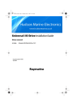
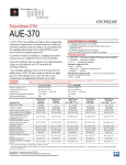
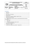
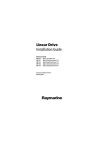
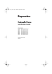
Universal
I/O Drive
Installation Guide
Drives covered:
E12026
Universal I/O (Stern) Drive 12 V
Document number: 81180-3
March 2001
2
Universal I/O Drive - Installation Guide
Important information
Safety notices
WARNING:
Product installation
This equipment must be installed and operated in accordance
with the instructions contained in this handbook. Failure to do so
could result in poor product performance, personal injury and/
or damage to your boat.
Because correct performance of the boat’s steering is critical for
safety, we STRONGLY RECOMMEND that an Authorized
Raymarine Service Representative fits this product.
WARNING:
Navigation aid
Although we have designed this product to be accurate and
reliable, many factors can affect its performance. As a result, it
should only be used as an aid to navigation and should never
replace commonsense and navigational judgement. Always
maintain a permanent watch so you can respond to situations as
they develop.
EMC conformance
All Raymarine equipment and accessories are designed to the best
industry standards for use in the recreational marine environment.
The design and manufacture of Raymarine equipment and
accessories conform to the appropriate Electromagnetic
Compatibility (EMC) standards, but correct installation is required to
ensure that performance is not compromised.
Handbook information
To the best of our knowledge, the information in this handbook was
correct when it went to press. However, Raymarine cannot accept
liability for any inaccuracies or omissions it may contain. In addition,
our policy of continuous product improvement may change
specifications without notice. As a result, Raymarine cannot accept
liability for any differences between the product and the handbook.
© Raymarine Ltd 2001.
Universal I/O Drive - Installation Guide
3
Introduction
Product description
Welcome to the installation guide for the Raymarine universal
inboard/outboard drive (also known as an I/O or stern drive). This
product is intended to operate the boat’s steering mechanism as part
of a Raymarine autopilot system.
CAUTION:
This drive is only designed to drive cable operated, power
assisted steering systems. Any attempt to install an I/O drive to a
non-compatible engine type may void the warranty on both the
drive and the engine.
The drive operates the power steering valve in the same way as the
steering cable. When you disengage the autopilot, a clutch
disengages the I/O drive so you can steer the boat manually.
Main motor, gear
and clutch assembly
Socket
for cable
Girdle tube
Drive cable
Rod end
Push rod
D5210-1
Figure 1: Main parts of the universal I/O drive
Contents
This guide contains:
1
Product specifications
page 4
2
Installation instructions
page 5
3
Maintenance information
page 14
4
Universal I/O Drive - Installation Guide
Specifications
Drive specifications
Table 1: Drive specifications
Performance
(at nominal voltage)
Universal I/O drive
E12026 (12 V)
Drive method
Electromechanical
Maximum thrust
50 kg (110 lb)
Maximum stroke
214 mm (8.3 in)
Hardover to hardover time
8.8 sec
Other information
protected for use in engine compartments
CE approvals - conforms to:
89/336/EC (EMC), EN60945:1997
94/25/EC (RCD), EN28846:1993
Drive dimensions
103 mm
(4 in)
62 mm
(2.4 in)
911 mm
(35.8 in)
1115mm
(43.8 in)
354 - 568 mm
(13.9 - 22.3 in)
D5186-1
Figure 2: Universal I/O drive dimensions
Universal I/O Drive - Installation Guide
5
Installation instructions
Parts required
To install the I/O drive the following parts are supplied:
•
•
•
•
•
universal I/O drive unit
power cable
adaptor pins for Mercruiser and Volvo engines
hexagonal bracket, securing bolts (x2), lock washers (x2)
fixing clamps (x2), self-tapping screws (x2) and tie-wraps (x2)
Installation steps
WARNING: Electrical safety
Make sure you have switched off the power supply before you
start installing this product.
Follow these steps to install your I/O drive unit:
1
Consult the EMC installation guidelines.
page 5
Ï
2
Mount the drive.
page 7
Ï
3
Connect the power cable.
page 12
Ï
4
Complete the post-installation checks.
page 13
1. EMC installation guidelines
All Raymarine equipment and accessories are designed to the best
industry standards for use in the recreational marine environment.
Their design and manufacture conforms to the appropriate
Electromagnetic Compatibility (EMC) standards, but correct
installation is required to ensure that performance is not
compromised. Although every effort has been taken to ensure that
6
Universal I/O Drive - Installation Guide
they will perform under all conditions, it is important to understand
what factors could affect the operation of the product.
The guidelines given here describe the conditions for optimum EMC
performance, but it is recognized that it may not be possible to meet
all of these conditions in all situations. To ensure the best possible
conditions for EMC performance within the constraints imposed by
any location, always ensure the maximum separation possible
between different items of electrical equipment.
For optimum EMC performance, it is recommended that wherever
possible:
•
•
•
•
Raymarine equipment and cables connected to it are:
• At least 3 ft (1 m) from any equipment transmitting or cables
carrying radio signals e.g. VHF radios, cables and antennas.
In the case of SSB radios, the distance should be increased to
7 ft (2 m).
• More than 7 ft (2 m) from the path of a radar beam. A radar
beam can normally be assumed to spread 20 degrees above
and below the radiating element.
The equipment is supplied from a separate battery from that used
for engine start. Voltage drops below 10 V, and starter motor
transients, can cause the equipment to reset. This will not damage
the equipment, but may cause the loss of some information and
may change the operating mode.
Raymarine specified cables are used. Cutting and rejoining these
cables can compromise EMC performance and must be avoided
unless doing so is detailed in the installation manual.
If a suppression ferrite is attached to a cable, this ferrite should not
be removed. If the ferrite needs to be removed during installation
it must be reassembled in the same position.
Suppression ferrites
Figure 3 shows typical cable suppression ferrites used with
Raymarine equipment. Use the ferrites supplied by Raymarine.
Connections to other equipment
If your Raymarine equipment is to be connected to other equipment
using a cable not supplied by Raymarine, a suppression ferrite MUST
always be attached to the cable near to the Raymarine unit.
Universal I/O Drive - Installation Guide
7
D3548-2
Figure 3: Typical Suppression Ferrites
2. Mounting the drive
CAUTION:
I/O drives are affected by substantial vibration during use. When
installing this I/O drive, make sure that you fully tighten all bolts
and use lock washers. Using a suitable thread-locking compound
on the threads will help keep the bolts securely tightened.
1. Select the correct adaptor pin for your engine type.
Volvo
Mercruiser
D4599-2
2. Remove the locating pin that attaches the steering cable rod to the
tiller block.
3. Replace it with the adaptor pin supplied, using the split pin to hold
it in place (see following figures).
8
Universal I/O Drive - Installation Guide
Adaptor pin
Tiller block
Aft
Steering cable rod
Fitting Volvo adaptor pin
D4532-2A
Steering cable rod
Tiller block
Adaptor pin
Aft
Fitting Mercruiser adaptor pin
D4532-2B
Universal I/O Drive - Installation Guide
9
4. Fit the supplied hexagonal bracket centrally on the existing
steering cable securing nut (see following figures). Secure the
bracket with one of the securing bolts and lock washers supplied,
ensuring that it is correctly aligned with the adaptor pin.
Fitting hexagonal clamp to Volvo
Ensure adaptor pin and
hexagonal bracket are in line
Hexagonal
bracket
Aft
D4587-3A
Fitting hexagonal clamp to Mercruiser
Aft
Hexagonal
bracket
Ensure adaptor pin and
hexagonal bracket are in line
D4587-3B
10
Universal I/O Drive - Installation Guide
5. Insert the metal cable end of the I/O drive into the clamp on the
hexagonal bracket:
• make sure the groove on the cable end fits onto the ridge inside
the clamp
• secure the clamp with the remaining securing bolt and lock
washer
6. Extend the I/O drive cable until the rod end is aligned with the
adaptor pin, then:
• fit the rod end onto the adaptor pin
• secure the rod end with the split pin supplied (see following
figures)
Rod end
Aft
Fitting cable to Volvo
D4534-3A
Universal I/O Drive - Installation Guide
11
Aft
Rod end
Fitting cable to Mercruiser
D4534-3B
7. Use the clamps and tie-wraps supplied to mount the main body of
the I/O drive in a suitable, safe position, remote from the engine.
CAUTION:
You can bend the drive cable when mounting the I/O drive, but
the bend radius must always be more than 100 mm (4 in).
D4535-1
12
Universal I/O Drive - Installation Guide
8. Complete a hardover to hardover check:
• Slowly turn the steering system from hardover to hardover.
• Make sure that the steering system operates freely and that the
drive unit and drive cable make no contact with any part of
the engine or boat.
Mounting in a restricted area
If an obstruction prevents you from installing the universal I/O drive
unit as supplied, rotate the girdle tube relative to the drive cable:
1. Loosen the grub-screws at the end of the girdle tube
2. Rotate the drive cable as required.
3. Remove the grub-screws one at a time, put thread-locking
compound on the thread, then replace and tighten the grub-screw.
4. Complete another hardover to hardover check.
3. Electrical connections
WARNING: Electrical safety
Make sure the power supply is switched off before you make any
electrical connections.
When you have fitted the I/O drive to the steering system, connect it
to the course computer as follows:
1. Plug in the power cable (supplied) into the socket on the drive
unit. Lock the connector in place by turning the locking ring
clockwise.
2. Route the cable to the course computer, taking into account the
EMC installation guidelines (see page 5).
3. Connect the motor cables (thicker blue and brown cables) and the
clutch cables (thinner red and black cables) to the connections on
the course computer as shown in Figure 4.
4. Secure the cable close to the I/O drive unit, making sure there is
enough free length to allow the drive unit to move.
5. Complete another hardover check: use the steering wheel to move
the rudder from hardover to hardover, and check that the cable
does not catch on any part of the boat or its fittings.
Universal I/O Drive - Installation Guide
13
Type 150/400 course computer
OFF
SWITCH
– +
A B
POWER MOTOR
– –
– +
SOLENOID CLUTCH
black
blue
Type 100/300 course computer
red
– +
lk CLUTCH
black
– +
1
2
POWER MOTOR
red
brown
blue
brown
D5184-2
Figure 4: Connections at course computer
4. Post-installation check
WARNING:
Keep clear of moving steering systems at all times. Protect
moving parts from access during normal use.
WARNING:
Only operate the autopilot system with the engines running and
power-assisted steering operating.
Check the following points after installing the drive:
1. Is the drive unit securely attached to the steering system (with all
brackets, bolts, split pins, etc. secure)?
2. Is the drive unit correctly aligned?
3. Are the motor and clutch cables correctly routed and securely
connected to the course computer?
4. Complete a hand-steering check: Are you sure there is no contact
between the drive unit and any part of the engine, steering system
or boat’s structure when the push rod moves in and out?
Note: When you have installed the entire autopilot system, you will
need to complete an autopilot steering check. Refer to the control unit
handbook for more details.
14
Universal I/O Drive - Installation Guide
Maintenance
On a regular basis:
•
•
•
check all connections and mountings are secure
check drive alignment
check cables for signs of wear or damage
EMC servicing and safety guidelines
•
•
•
•
•
Raymarine equipment should be serviced only by authorized
Raymarine service technicians. They will ensure that service
procedures and replacement parts used will not affect
performance. There are no user serviceable parts in any
Raymarine product.
Some products generate high voltages, so never handle the
cables/connectors when power is being supplied to the
equipment.
When powered up, all electrical equipment produces
electromagnetic fields. These can cause adjacent pieces of
electrical equipment to interact with one another, with a
consequent adverse effect on operation. In order to minimize
these effects and enable you to get the best possible performance
from your Raymarine equipment, guidelines are given in the
installation instructions, to enable you to ensure minimum
interaction between different items of equipment, i.e. ensure
optimum Electromagnetic Compatibility (EMC).
Always report any EMC-related problem to your nearest
Raymarine dealer. We use such information to improve our
quality standards.
In some installations, it may not be possible to prevent the
equipment from being affected by external influences. In general
this will not damage the equipment but it can lead to spurious
resetting action, or momentarily may result in faulty operation.
Universal I/O Drive - Installation Guide
15
Product support
Raymarine products are supported by a worldwide network of
distributors and Authorized Service Representatives.
If you encounter any difficulties with this product, please contact
either your national distributor, or your service representative, or the
Raymarine Technical Services Call Center. Refer to the back cover
or the Worldwide Distributor List for contact details.
16
Raymarine Ltd
Anchorage Park
Portsmouth, Hampshire
England PO3 5TD
Telephone +44 (0)23 9269 3611
Fax +44 (0)23 9269 4642
www.raymarine.com
Universal I/O Drive - Installation Guide
Raymarine Inc
22 Cotton Road, Suite 280
Nashua
NH 03063-4219, USA
Telephone +1 603 881 5200
Fax +1 603 864 4756
www.raymarine.com
Raymarine Technical Services Call Center
UK: +44 (0)23 9271 4713 or
USA: +1 603 881 5200 or
+44 (0)23 9269 3611 ext. 1083
1-800-539-5539 ext. 2333