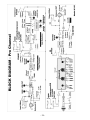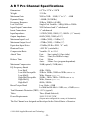
1
Pro Channel
TUBE MIC PREAMP / COMPRESSOR / EQUALIZER
USER’S GUIDE
Contents
FEATURES......................................................................... 5
OVERVIEW ........................................................................ 6
WHY USE AN EXTERNAL PROCESSING CHANNEL? ...............................6
DESIGN NOTES..................................................................................6
SETTING UP ...................................................................... 7
UNPACKING ......................................................................................7
AC POWER HOOKUP .........................................................................7
AUDIO CONNECTIONS ........................................................................7
INSTALLATION ...................................................................................8
SAFETY PRECAUTIONS ......................................................................8
POWERING UP ...................................................................................8
FRONT PANEL CONTROLS AND INDICATORS ................. 9
PREAMP CIRCUIT...............................................................................9
Gain Control.............................................................................................9
Gain Switch..............................................................................................9
Phantom Switch .......................................................................................9
Phase Switch .........................................................................................10
Tube Drive/Gain Reduction Display.......................................................10
Preamp Output Control ..........................................................................10
COMPRESSOR CIRCUIT ....................................................................11
Threshold Control ..................................................................................11
Ratio Control ..........................................................................................11
Attack Switch .........................................................................................12
Release Switch ......................................................................................12
Type Switch ...........................................................................................12
Comp Bypass Switch .............................................................................12
Compressor Output Control ...................................................................12
-2-
CLIP INDICATOR .............................................................................. 13
EQUALIZER CIRCUIT ........................................................................ 13
Low Control ........................................................................................... 13
Low Switch ............................................................................................ 13
Lo-Mid Control ....................................................................................... 14
Lo-Mid (X 10/Norm) Switch ................................................................... 14
Lo-Mid (Narrow/Wide) Switch................................................................ 14
Hi-Mid Control........................................................................................ 14
Hi-Mid (X 10/Norm) Switch .................................................................... 14
Hi-Mid (Narrow/Wide) Switch ................................................................ 14
High Control........................................................................................... 15
High Switch............................................................................................ 15
EQ Byp Switch....................................................................................... 15
MASTER CONTROLS........................................................................ 16
Master Output Control ........................................................................... 16
VU Meter ............................................................................................... 16
VU Meter Switches ................................................................................ 16
Power .................................................................................................... 16
REAR PANEL CONNECTIONS ..........................................17
INPUT AND OUTPUT CONNECTIONS .................................................. 17
Input....................................................................................................... 17
Output.................................................................................................... 17
XLR GND Switch ................................................................................... 17
LOOP INSERTS ................................................................................ 17
Preamp - Compressor Loop .................................................................. 18
Compressor - EQ Loop.......................................................................... 18
Loop Connection Examples................................................................... 18
APPLICATIONS ................................................................19
EQ TIPS ......................................................................................... 19
What is the best way to use EQ? .......................................................... 20
SPECIAL EFFECTS .......................................................................... 21
-3-
GROUNDING ....................................................................................21
TUBE REPLACEMENT ..................................................... 21
WE’RE ON-LINE! .............................................................. 22
WARRANTY AND SERVICE INFORMATION .................... 22
LIMITED WARRANTY ........................................................................22
SERVICE .........................................................................................22
BLOCK DIAGRAM ............................................................ 24
A R T PRO CHANNEL SPECIFICATIONS ......................... 25
-4-
Features
The Pro Channel is a unique product. It contains three independent, award-winning
circuit designs: one of the finest tube microphone preamplifiers available, one of the
finest optical tube compressors available, and one of the most flexible EQs you’ve ever
used. Developed in partnership with studio and live sound engineers, the Pro Channel
possesses a “sound” that is not available from any other product on the market – at any
price! The Pro Channel was designed and constructed with the best components,
assuring a lifetime of quiet, reliable performance. The Pro Channel offers the following:
• The award winning A R T “SOUND”!
• Very low-noise, tube-based mic/line preamplification with discreet, Class-A solidstate input circuitry
• Both electro-optical and tube compressor designs
• Tube-based, semi-parametric, four-band equalization with selectable frequency ranges
and Q
• Three hand-selected tubes
• VCA-less compressor circuitry (i.e., transparent dynamics control)
• Unique tube character and gain reduction LED metering
• Large 3” analog VU metering to monitor Output and Send points
• Bypassable compression and equalization circuitry
• XLR balanced inputs and outputs
• ¼” TS unbalanced inputs and outputs
• A rugged steel and aluminum chassis
• ¼” unbalanced insert points between the preamp and compressor and between the
compressor and equalizer
• +48V phantom power
• Phase reversal
• Detented rotary controls
• Variable threshold and compression ratios
• Selectable attack and release time settings
• >90dB of dynamic range
• An internal power supply
• A five year warranty
• Designed in the USA
-5-
Overview
Why use an external processing channel?
The best way to get a signal to tape is by using the shortest signal path. In most cases,
the shortest path is as follows: mic to preamp to compressor to EQ to tape. (The signal
doesn’t even go through a mixer!) This isn’t a new concept, but it has become more
relevant with the availability of affordable mixing consoles.
As their name implies, most affordable mixers are optimized for signal routing and
general level mixing. However, they are not necessarily your best option for the actual
recording of tracks. The simple truth is that the Pro Channel has a better sounding and
more flexible collection of circuits. Mixer manufacturers need to make tradeoffs
between price and performance. Imagine the price of your mixer if each channel’s EQ
cost over $200 (we’re not talking to those of you who have a $250,000+ console)! For
those of us on a budget, it just doesn’t make sense to spend a ton of money on a
“Cadillac” console when a budget mixer and a few pieces of external gear is more cost
effective. Even those engineers who regularly work on “big” consoles use external EQs,
compressors, and preamps!
The goal of any recording is to get the sounds right before you commit them to tape.
The Pro Channel helps you get it right so you don’t have to “fix it in the mix.”
Design Notes
The Pro Channel is a multi-purpose tool for audio engineering and recording. Enclosed
in a two rack space (2U) chassis are three independent circuits featuring a tube-based
analog preamplifier, a VCA-less compressor (selectable between optical or tube control
elements), and a semi-parametric, tube-based equalizer.
The Pro Channel is designed to work seamlessly with any recording, soundreinforcement, or electronic instrument setup. A R T’s Pro Channel circuitry is a hybrid
design utilizing the most advanced solid-state and tube technology. With a
transformerless power supply, the Pro Channel maintains exceptional signal integrity
and extremely low noise.
Signal flow within the Pro Channel is from the preamp, to the compressor, to the
equalizer (although you can change the order of the circuits by utilizing the insert
points). While the preamp is always active, the compressor and equalizer may be
individually bypassed. The preamplifier’s active, balanced, solid-state input provides
extremely low noise and excellent CMRR (Common Mode Rejection Ratio).
The ¼” input has a high impedance, which prevents the loading of any device connected
to it and makes the Pro Channel perfect for DI or line level applications. The
preamplifier’s second stage 12AX7a tube runs on a regulated DC voltage, providing an
additional 20dB of gain. Our design enables the tube to overload before the input or
output stage, allowing you to manipulate the tube gain to meet different sonic criteria.
-6-
The compression circuit features a VCA-less design and utilizes either optical
(Vactrol®) or tube, dual triode electronics for superior musical performance. The
compressor is soft knee by design. Although it is capable of providing a thoroughly
“squashed” signal, it was designed to excel in areas where transparent and musical
dynamics control is desired. The beauty of the optical design is its ability to apply heavy
amounts of compression without pumping and breathing like VCA-based compressors.
The tube compressor is capable of smoothly compressing fast-rising signal sources
without undue side effects. In most cases you will hear the results of the compression
without hearing the compressor.
The tube-based equalizer was designed to help “fix” the instruments that give us
headaches when recording (i.e., kick, snare, bass, toms, guitar amps, voice, etc.). The
two sweepable parametric bands and selectable shelving bands have been optimized for
musical instruments. The two sweepable bands overlap each other as well as the high
and low shelving bands, providing you with the ultimate in flexibility. This EQ design
gives you all the control you need to effectively dial in great sounds from even the
poorest of sources.
Setting Up
Unpacking
Your Pro Channel was packed with care at the factory. The shipping carton was
designed to protect the unit during initial shipment. Please retain this carton for use in
transporting the Pro Channel, or in the unlikely event that you need to return your unit
for servicing.
AC Power Hookup
The Pro Channel has an internal power supply designed to operate at 100 to 125VAC,
50 to 60Hz. Units manufactured for use outside of the United States have been modified
to comply with the required electrical specifications. Under no circumstances should the
power cable be altered. If the cable becomes cut or damaged, discontinue use and have
it replaced before operating.
Audio Connections
Audio connections to and from the Pro Channel are balanced XLR (Pin 2 = Hot (+), Pin
3 = Cold (-), Pin 1 = Ground) and unbalanced ¼” (Tip = Hot (+), Sleeve = Ground).
The insert points between the preamp and compressor and the compressor and equalizer
are unbalanced ¼” (Tip = Hot (+), Sleeve = Ground) connectors.
We recommend using only high-quality cables and connectors.
-7-
Installation
The Pro Channel may be employed in a number of setups, including:
• between a microphone and a digital recorder, mixer, or analog recorder;
• in a mixer’s channel insert points;
• between a microphone and signal processors; and
• between electronic musical instruments (synthesizers, guitars, basses, samplers,
acoustic instruments with pickups, etc.) and other gear.
Safety Precautions
WARNING: To avoid the risk of shock or fire, do not expose this unit to moisture. Do
not remove metal panels or chassis parts. Removing any chassis parts exposes
dangerous high voltages. There are no user-serviceable parts inside. Refer all servicing
to qualified personnel.
If your power cord becomes damaged, always replace it with the same type as originally
equipped. Since the cord is detachable, it is possible to replace it with a cord configured
for the wrong voltage. Always refer to the unit’s rear panel to determine the correct
supply voltage, and then choose an appropriate cord.
Powering Up
When the power switch is turned on, the VU meter illuminates. It is important to
remember to turn the Pro Channel on before any monitoring levels or power amps are
turned on. The Pro Channel has the ability to add over 80dB of gain to its input signal
and can cause the unit to produce a “thump” on power up and power down.
Like all tube-based equipment, the Pro Channel needs to warm up before being used.
Allow one to two minutes for the tubes to reach their proper operating temperature. If
the Pro Channel fails to power up when the power switch is turned on, check to see that
its power cord is plugged into an active outlet. If the unit still fails to operate properly,
turn it off and unplug it, and then consult your dealer or A R T’s Customer Service
department.
-8-
Front Panel Controls and Indicators
Preamp Circuit
Gain Control
The Gain control sets the Pro Channel’s
input gain. Turn the control clockwise to
increase gain and counter-clockwise to
decrease it. The front panel calibrations
(-11dB to +30 dB) refer to the Gain Switch
(see next section) in the “Norm” position
with the input routed to the ¼” unbalanced
input jack. Using the XLR (balanced) input
connection results in 12dB more gain, thus
making the control range from +1dB to
+42dB. When setting the Gain control, refer
to the first 10 segment Tube Character
Array (directly under the VU meter) for a
visual reference to the Pro Channel’s
internal signal levels.
Hint: The Pro Channel’s “sweet spot” is
when all four of the yellow “warm” LEDs in the Tube Character meter are lit and the
first red “clip” LED flashes occasionally.
Gain Switch
Use the Gain switch to add 20 dB of gain to the Gain control’s range (described above).
With the switch in, the gain range is +9 to +50dB using the unbalanced input (or +21 to
+62dB using the balanced input).
Note: With most microphone applications, you’ll find it necessary to use the Pro
Channel with the +20dB gain switch in. (Use the setting that best fits your application.)
Phantom Switch
The Pro Channel can power any microphone needing +48 volts DC phantom power.
Consult your microphone’s documentation to see if phantom power is required. Turning
the Phantom switch on supplies power to pins 2 and 3 of the balanced XLR input jack.
Note: Be sure to turn down or mute the output of the Pro Channel when turning
phantom power on or off. Allow 30 - 45 seconds for the power to completely dissipate
-9-
before disconnecting microphones.
Another Note: Most dynamic microphones won’t be affected or damaged if they are
plugged into the Pro Channel when phantom power is turned on (we haven’t run across
any). However, if the mic doesn’t need it, don’t use it. Some things are best left
untested!
Phase Switch
The Phase switch is used to reverse the phase of the signal leaving the Pro Channel’s
preamp section. The Phase switch reverses the polarity of the Preamp Output jack and
everything after it in the signal chain. In the Normal position (out), the signal is inphase. In the Reverse position (in), the polarity of Pins 2 and 3 of the Output XLR jack
(and the Tip of the ¼” jacks) are reversed and the signal is changed to 180 degrees out
of phase with the input signal.
In multiple microphone applications, mic placement can affect the phase of a signal. If
two microphones pick up the same signal from different locations, the result can be a
hollow or “frequency-shifted” sound; in some cases it may sound as if an instrument
disappears completely. Depressing the Phase switch can remedy this problem.
Note: In single microphone applications, switching the phase will produce no audible
change in the output signal.
Tube Drive/Gain Reduction Display
The top LED display (directly under the VU meter) shows how the tube gain is affecting
the input signal. These LEDs are calibrated with the tube circuitry to give you an
accurate representation of the tube’s output signal. The Tube Character LEDs measure
the signal level before the Preamp Output level control—use them as a visual guide for
setting the Gain control.
The first four (green) LEDs are labeled “Cln.” The tube is producing a clean output
when these are lit. The next four (yellow) LEDs are labeled “Warm.” This is the optimal
operating range for the Pro Channel’s preamp. At this level, the tube is producing an
output signal that most would term “warm” (or whatever you’d like to call it—
simmering, toasty, etc.) You’ll find the output signal has an enhanced bottom to low
mid quality with smooth high frequency detail.
The last two (red) LEDs are labeled “Clip.” The first red LED will light approximately
6dB before audible distortion occurs. If this light flickers, don’t panic. The unique
design of the Pro Channel allows the tube to distort well before any other gain stage.
When a tube goes into distortion, it’s a gradual process and tends to sound pleasing for a
range before it turns into a distortion box. You may also find that a “clipped” level is
suitable for some applications.
Preamp Output Control
The Preamp Output control sets the output level of the preamp section. In most
situations you’ll set this control around 12 o’clock (or its “0” setting). The Preamp
Output control has a range of no output (from its fully counter-clockwise position), to
- 10 -
+10dB of gain (when turned fully clockwise).
When setting up the preamp, start with the Preamp Output at its “0” position. Once you
get the Gain control set the way you want it to sound, use the Preamp Output control to
set the level out of the preamp (much like using the master volume control on a guitar
amplifier). Use the Preamp Output control to recover gain when you have the Gain
control set low for a “clean” sound. Likewise, you can use the Preamp Output control to
decrease the level out of the preamp when you’re cranking the Gain control up for
maximum tube warmth. Don’t be afraid to set the Preamp Output control very high if
you desire a very clean signal, but with a good deal of compression. (See the next
section.)
Compressor Circuit
Threshold Control
The Threshold control sets the point at which
the compressor acts on the input signal.
Turning this control counterclockwise lowers
the Threshold, adding more compression to a
signal. Turning this control clockwise raises
the threshold.
The Threshold control is dependent on the
Preamp Output control (or the output of a
device plugged into the Comp In insert point).
The easiest way to set this control is to start
with it fully clockwise. After setting the
Preamp Output level, slowly turn the
Threshold control counter-clockwise,
(lowering the threshold) until you see the
yellow (0dB) Threshold LED light in the Gain
Reduction display (below the Tube Character
array). Now adjust Threshold (either lower or higher) until you have the desired amount
of compression. (Use the Gain Reduction LEDs as a visual guide)
Ratio Control
The Ratio control sets the compression ratio (or slope) for the compressor circuit. At its
minimum position, the compression ratio is an active 2:1, meaning that for every 2dB
over the threshold the input signal rises, the compressor’s output will change by 1dB.
This compression ratio is very mild and musical, and is ideal for smoothing all types of
signals. At its maximum position, the compression ratio is greater than 10:1. This
setting is typically called “hard limiting” as it allows only a 1dB change in level for any
signal reaching 10dB above the set threshold. Hard limiting is ideal for applications
where it is not desirable to exceed a certain level (i.e., mixing, popping bass, digital
recording, etc.).
- 11 -
Attack Switch
The Attack switch selects the attack characteristics of both the tube and optical
compressor circuits. The Fast position (in) allows the compressor to react quickly to
fast-rising attacks. Note that the tube circuit has an inherently fast response and can be
aggressive on signals with quick transients, such as snare drums. The Slow position
(out) can be helpful in reducing compression artifacts for signals with very little high
frequency content, such as piano or flute.
Release Switch
The Release switch selects the release characteristics of the compressor circuit. The Fast
position (in) allows the compressor to recover quickly once the signal falls below the
threshold. The Auto position (out) allows the compressor to adjust itself depending on
the characteristics of the input signal. Use the Fast setting when the signal has repetitive,
consistent characteristics, such as on kick drums, snares, and vocals. Use the Auto
setting when the signal has varying characteristics, such as long decaying notes
alternating with quick notes and mix material.
Type Switch
This switch covers one of the more unique features of the Pro Channel. In the Optical
position (out), the Pro Channel’s compressor employs A R T’s award-winning
Vactrol®-based compression element from the Pro VLA. Switching to the “in” position
engages the dual-triode, tube control element. This circuit is capable of considerably
faster attack and release times than its optical counterpart. Experiment with the two
types of compression to become familiar with how they react to different source
material.
Comp Bypass Switch
A Bypass switch is included on the compressor circuit to enable you to remove it from
the signal chain. In its Norm position (out), the compressor is active. When set to its
Bypass position (in), signal passes from the preamp circuitry to the equalizer without
compression and the adjacent red LED lights. Also, the Gain Reduction LED array
operates as usual, though at a much dimmer level, to remind you that the compressor is
out of the signal path.
Use the Comp Bypass switch to achieve unity gain at the output of the Compressor.
Unity gain is achieved when the compressor’s active level is the same as its bypassed
level. Toggle the switch between Norm and Bypass while adjusting the Compressor
Output level. Once the levels are the same (use your ears and the VU Output Level
meter), you’ve reached the compressor’s unity setting.
Compressor Output Control
The Compressor Output control sets the output level from the compressor circuit.
Typically, a compressor’s Output control is used to add gain to compensate for the
amount lost due to compression.
When the control is fully counter-clockwise, the output is off. Turning the control
- 12 -
clockwise increases the level to a maximum of +20dB of gain. While you can use the
compressor to add gain to a signal, it is better to add gain before the compressor for the
best signal to noise ratio. If you want to use the compressor to add more gain, use the
VU meter to monitor the Pro Channel’s output level, or use the meter on your recorder
or mixer to make sure you won’t clip the next piece of equipment in the chain.
Clip Indicator
The red Clip LED, located between the compressor and EQ sections, monitors the EQ’s
level at several internal points. It will illuminate 6dB before the available headroom is
exceeded. When the Clip indicator lights, the level into the equalizer is too high; turn
down either the Preamp Output control, the Compressor Output control, or the output
level of the device plugged into the Comp In insert point.
Equalizer Circuit
The equalizer circuit in the
Pro Channel is a tube-based,
semi-parametric, four-band
equalizer. All of the bands
overlap, giving you the
ultimate in flexibility. The
normal bandwidth of each
filter is purposely wide to
provide a very musical
sound.
Low Control
The Low control adjusts a
shelving filter with a
selectable corner frequency
of either 40Hz or 120Hz.
The two frequencies are selected with the Low switch (see below). The low shelving
filter affects all frequencies below the corner frequency when applying boost or cut. In
other words, cutting at 40Hz also cuts 30Hz, 20Hz, etc. The Low control has as range of
±12dB.
Low Switch
The Low switch selects the corner frequency of the Low control. In the “out” position,
the corner is at 40Hz. In the “in” position, the corner is at 120Hz.
40Hz is great for enhancing sub-low frequencies such as those in bass guitars and kick
drums. Cutting 40Hz can also help to “clean up” mixes that sound muddy or “loose” in
the low end.
120Hz is generally the low-end for vocals, guitars and toms. Boosting 120Hz can add
- 13 -
“weight” or “beef” to a week vocal and cutting it can “thin out” a signal that takes up
too much room in the low end.
Lo-Mid Control
The Lo-Mid control is a dual concentric pot (i.e., there are two controls – one outer and
one inner). The outer control is used to select a frequency while the inner one is used to
apply boost or cut. The amount of boost or cut available depends on the setting of the
Lo-Mid (Wide/Narrow) switch: ±12dB for Wide and ±20dB for Narrow. Bandwidths
are approximately 1 octave and 1/3 octave, respectively. Also, the Lo-Mid control can
cover two frequency ranges depending on the position of the Lo-Mid (X 10/Norm)
switch; these ranges are 20Hz to 200Hz and 200Hz to 2KHz.
Lo-Mid (X10/Norm) Switch
The first Lo-Mid switch determines the frequency range covered by the Lo-Mid control
(above). In its “out” position, the range is set at 20Hz to 200Hz. In its “in” position, the
range is set at 200Hz to 2KHz. You’ll notice that the Low and Lo-Mid control ranges
overlap (meaning they cover the same frequencies); this is intentional and is one of the
powerful features of the equalizer.
Lo-Mid (Narrow/Wide) Switch
The second Lo-Mid switch determines the width of the frequency band that the Lo-Mid
control covers. In its Wide position (out), the Q is approximately 1.1. In its Narrow
position (in), the Q is approximately 3.3. In general, you’ll find that the Wide setting
yields the most musical, unobtrusive results. Conversely, Narrow is preferable for
“surgical” cutting of a frequency band without affecting adjacent frequencies too much.
Hi-Mid Control
Like the Lo-Mid control, the Hi-Mid control is a dual concentric pot. The outer control
is used to select a frequency while the inner control is used to apply boost or cut. The
Hi-Mid control can cover two frequency ranges, depending on the position of the HiMid (X 10/Norm) switch; these ranges are 200Hz to 2KHz and 2KHz to 20KHz.
Hi-Mid (X 10/Norm) Switch
The first Hi-Mid switch determines the frequency range covered by the Hi-Mid control
(above). In its “out” position, the range is set at 200Hz to 2KHz. In its “in” position, the
range is set at 2KHz to 20KHz.
Note: The Lo-Mid and Hi-Mid Frequency controls overlap in the 200Hz to 2KHz range.
This feature allows either or both controls to be used in this range and is extremely
useful if, for example, you want to cut at 200Hz and boost at 350Hz.
Hi-Mid (Narrow/Wide) Switch
The second Hi-Mid switch determines the width of the frequency band that the Lo-Mid
control covers. In its Wide position (out), the Q is approximately 1.1. In its Narrow
position (in), the Q is approximately 3.3. In general, you’ll find that the Wide setting
yields the most musical, unobtrusive results. Conversely, Narrow is preferable for
- 14 -
“surgical” cutting of a frequency band without affecting adjacent frequencies too much.
High Control
The High control adjusts a shelving filter with a selectable corner frequency of either
6KHz or 18KHz. The two frequencies are selected with the High switch (see below).
The high shelving filter affects all frequencies above the corner frequency when
applying boost or cut. In other words, cutting at 6KHz also cuts 7KHz, 8KHz, etc. The
High Frequency control has as range of ±12dB.
High Switch
The High switch selects the corner frequency of the High control. In the “out” position,
the corner is 18KHz. In the “in” position, the corner is 6KHz.
6KHz is great for adding top end to guitars, snare drums and vocals. Cutting 6KHz can
also help to take the edge off brittle or harsh sounding instruments.
18KHz may be used to add “sizzle” to cymbals and is generally referred to as the “air”
band. While there aren’t many instruments that contain 18KHz information directly,
many instruments and mixes contain upper harmonics that can add extra definition and
space when boosted. Cutting at 18KHz can decrease hiss and noise.
Note: The High and Hi-Mid controls intentionally overlap to give you greater
flexibility. For example, on cymbals try boosting 18KHz with the High control while
cutting 20KHz with the Hi-Mid control for a bright, yet noise-free result.
EQ Bypass Switch
A Bypass switch is included in the equalizer circuit to enable you to remove it from the
signal chain. When set to its Bypass position (in), signal passes from the compressor
circuitry to the output tube section with no equalization. The red LED lights when
Bypass is engaged. In its Norm position (out), the equalizer is active. Use the EQ
Bypass switch to compare your equalized and unequalized sound – a reality check to
make sure you are making an improvement! It may be necessary to adjust the Master
Output control to balance the apparent level of the EQ’d and un-EQ’d signal.
- 15 -
Master Controls
Master Output Control
The Master Output control
sets the final output level
leaving the Pro Channel.
When the control is fully
counterclockwise, there is
no output. Turning the
control clockwise increases
the output level to a
maximum gain of +10dB.
When setting this control,
refer to the VU Meter (set
for the “Output” option—see below) or the level meter on your recorder or mixer.
VU Meter
A backlit, average reading VU meter can accurately monitor levels at several points in
the Pro Channel. The “0VU” level is calibrated to +4dBu at any of the internal points
and at the ¼” Output connector. For the same calibration on the XLR output, a 600Ω
load must be used otherwise the balanced output is 6dB higher (0VU = +10dBu).
Note: When running the Pro Channel into a mixing console or recorder, always
reference the meter on the mixer or recorder when setting output levels. Not all meters
are calibrated the same and it is always best to look at the level entering the last piece of
equipment in the chain.
VU Meter Switches
The VU Meter switches determine which point feeds the VU meter. The right-hand
switch selects either the Pro Channel’s output or an internal point selected by the other
switch. The left-hand switch selects either the preamp output or the compressor output.
Note: When the right-hand switch is set to Output, the left-hand switch has no effect.
Another Note: The internal level-monitoring points also correspond to the level at the
Send jacks of the two insert loops. If you are using either of these jacks as your output
to other devices, switch the VU Meter to monitor the appropriate point.
Power
The Power switch supplies and removes power from the Pro Channel. The Pro Channel
should be turned on only after all monitor levels are turned down or off, to protect
against any “thumping” caused by high gain settings. Likewise, the Pro Channel should
be turned off after turning all monitor levels down.
The Output Level VU meter is illuminated when power is on.
- 16 -
Rear Panel Connections
Input and Output Connections
The Pro Channel’s XLR connectors follow the AES standard: Pin 1 = Ground, Pin 2 =
Hot (+), and Pin 3 = Cold (-). The unbalanced ¼” phone jacks are the typical Tip = Hot
(+) and Sleeve = Ground.
Note: None of the Pro Channel’s circuitry is connected directly to the metal chassis.
Either the input or output ground must be connected to another portion of the signal path
in order to establish a ground reference.
Input
Only one Input jack should be used at a time. However, both inputs can be hard-wired
without having to disconnect one while using the other (i.e., if no load is placed on the
XLR input, the ¼” jack will function as if there was nothing connected to the XLR
input). However, it is still preferable to disconnect any unused cables to avoid pick up of
extraneous noise, hum, or RF interference.
Output
Both the balanced and unbalanced Output connections may be used simultaneously.
This feature is particularly handy when using the Pro Channel as a direct box for
instruments or line level signals.
XLR GND Switch
If you hear a hum when using the Pro Channel’s XLR output, a ground loop may be the
problem. To remedy this problem, press the XLR GND switch in, to its “Lift” position,
to disconnect the ground wire (pin 1) from the XLR output. This action interrupts the
ground path and therefore breaks the loop.
Loop Inserts
Two signal loops are provided for the following applications: to connect external
equipment to the Pro Channel, to use only specific individual circuits, or to take direct
signal paths from specific sections. The connections are unbalanced ¼” (Tip = Hot (+),
Sleeve = Ground). Both of the Send jacks may be used without interrupting signal-flow
through the Pro Channel. The Return jacks break the signal-flow when a jack is
inserted.
- 17 -
The loops may also be utilized to “re-patch” the compressor and equalizer circuits in a
different order (i.e., signal flow = preamp to equalizer to compressor). For information
on how to do this, see Loop Connection Examples, below.
Preamp - Compressor Loop
A loop is provided between the preamp’s output and the compressor’s input. The
Preamp Out (Send) jack takes its signal after the Preamp Output control. This jack may
be used to send an unbalanced signal directly to an input of a recorder, mixer, or other
piece of outboard equipment.
The Comp In (Return) jack places its signal before the compressor’s Threshold control.
This jack may be used to connect the output of a piece of equipment to the input of the
Pro Channel’s compressor circuit. Since there is no Compressor Input Level control,
equipment patched into the insert loop should have an Output control for setting proper
levels.
Compressor - EQ Loop
A loop is provided between the compressor’s output and the equalizer’s input. The
Comp Out (Send) jack takes its signal after the Compressor Output control. This jack
may be used to send an unbalanced signal directly to an input of a recorder, mixer or
other piece of outboard equipment.
The EQ IN (Return) jack may be used to connect the output of a piece of equipment to
the input of the Pro Channel’s equalizer circuit. Since there is no Equalizer Input Level
control, equipment patched into the insert loop should have an Output control for setting
proper levels.
Loop Connection Examples
To use only the Pro Channel’s preamp: Plug a mic, instrument, or line level signal
into one of the Input jacks. Either connect the Preamp Out (Send) jack into the input of
the next piece of gear, or bypass the compressor and equalizer circuits and connect
either of the Output jacks to the input of the next piece of equipment.
To use only the Pro Channel’s compressor: Plug a line level signal (such as a mixer’s
Send) into the Comp In (Return) jack. Connect the Comp Out (Send) jack to the input of
the next piece of equipment, such as a mixer’s Return.
To use only the Pro Channel’s equalizer: Plug a line level signal into the EQ In
(Return) jack. Connect either of the Pro Channel’s Outputs to the input of the next piece
of equipment.
To place the equalizer before the compressor: Plug a mic, instrument, or line level
signal into one of the Input jacks. Connect Preamp Out (Send) to EQ In (Return).
Connect the unbalanced Output to Comp In (Return). Use Comp Out (Send) as the main
output to the input of the next piece of equipment.
Don’t forget that it is possible to use each section of the Pro Channel on a separate
track. For example, the bass track can run through the compressor, the vocal track
through the preamp, and the guitar track through the EQ – all at the same time!
- 18 -
Applications
The Pro Channel’s main application is as a processing channel for a microphone,
instrument, or line level source. To use the Pro Channel as a mic or line preamplifier
only, simply press the Bypass switches to bypass the compression and equalizer
circuitry. Plug a microphone directly into either input and set the Input and Output
controls to provide an appropriate level into the next stage of your system. The Pro
Channel is ideal for use as a DI box. Plug your instrument into either Input and use the
XLR, ¼”, or both outputs to connect to your recorder, board, or PA system. Experiment
with different input level settings for distinct textures.
The Pro Channel has enough gain to be used in front of a power amplifier. To use the
Pro Channel as an instrument preamp, simply plug the instrument into the Input jack
and connect the Output jack to the power amplifier’s Input. See Loop Connections for
further hook-up options and for using the Pro Channel’s individual sections.
In most cases, the Pro Channel offers superior performance to your console’s on-board
preamp. To use the Pro Channel instead of your console’s preamp, simply connect the
Pro Channel’s Output to the Line Input of your mixer’s input channel.
Note: You can connect the XLR Output jack of the Pro Channel to the XLR Input of
your mixer, however most affordable mixers do not allow you to bypass their internal
preamp when using the XLR jack. You will cause no harm to either unit when doing
this, but you will probably experience slightly higher noise due to the fact that you are
now preamplifying your mixer’s preamp.
Note: Be certain that you do not connect the Pro Channel’s XLR Output to a mixer
input that has Phantom Power applied.
EQ Tips
- 19 -
What is the best way to use EQ?
There are two schools of thought on EQ:
1) Use as much as you need to make things sound good.
2) Don’t use any EQ.
Most people follow the suggestion of “if it sounds good, it is good.” You need to use
your ears and judge for yourself as their are no steadfast rules for EQ’ing. Here are a
few pointers to guide you:
• Always tweak the instrument you are EQ’ing while listening to it in the mix. EQ’ing
an instrument when it is soloed doesn’t give you a good representation of how it will
sound when mixed with other instruments. You’d be surprised at how bad a killer
guitar track can sound when it is isolated from the rest of the mix. Remember, what
makes it killer is how it sounds in relation to the other instruments! Keep the big
picture in mind.
• Most people think of EQ as boosting only (“we’ll just add a little EQ...”). Many
times a “bad” sounding instrument can be fixed by simply isolating the offending
frequency and pulling it out. After you determine approximately where the “problem
area” is in the instrument (highs, lows, mids), isolate the track and boost one of the
mid bands. Slowly sweep through its frequency range. When the really nasty sound
jumps out at you (you’ll know it when it happens) turn the boost back to “0” (12
o’clock). Now put the track back into the mix and cut the frequency. You’ll have to
adjust the level of the instrument depending on how much you cut, but you should
find that with the problem area pulled out, the instrument works better in the mix.
• When recording EQ’d instruments, make sure you have a good representation of
frequencies on tape. Always monitor “off-tape” when recording to ensure that what
you’re hearing is what is on tape. When recording things like kick drums, make sure
you have enough low end “thud” and high end “click” (if applicable) before you
record.
Recording guideline: You can always boost or cut frequencies after they’ve been
recorded, but you can’t add frequencies that weren’t recorded! Also, if you get the
right sound when you record the tracks, you shouldn’t be spending a lot of time reEQ’ing during the mix.
• When mixing, concentrate on blending tracks and the song’s dynamics. If you find
yourself EQ’ing everything, take a break and come back to it later. Start mixing with
a group of instruments such as the whole drum kit or guitars and bass, instead of
listening to individual tracks. Mixing is the time for tweaking – not applying a sonic
re-design. Once again, “if it sounds good, print it!” Trust your ears – never mind
where the knobs are pointing.
- 20 -
Special Effects
For industrial, metal, or just “flavor” textures, experiment with the Pro Channel.
Overdriving the preamp, compressor, and equalizer circuitry can add interesting textures
when blended with vocals and other instruments. Purposely placing signals out of phase
can also yield interesting results. No harm will come to the Pro Channel with this type
of experimentation. However, be sure to have output and monitoring levels turned
DOWN before “testing” the sound. Remember, you have a great amount of gain
available in the Pro Channel!
Grounding
Avoiding ground loops while several pieces of equipment are connected is one of the
most common challenges in recording. For this reason, all ART recording gear does not
have a direct connection between the audio circuit ground and the chassis ground. This
technique enables the gear to be safely grounded through the 3-prong AC cord and also
to the previous and next items in the signal chain—with optimum noise performance.
At least one ground connection must be made between the Pro Channel and the rest of
the signal chain. If you hear hum when using the Pro Channel’s XLR output, try
pressing the XLR GND switch in, to its “Lift” position, to disconnect the ground wire
(pin 1) from the XLR output.
Tube Replacement
The Tubes in your Pro Channel should last for many years. They are hand-sorted for
optimal performance in our specific circuits. In the event that you need to replace them,
A R T suggests that you do so with tubes available from A R T. These are matched to
the Pro Channel and will yield consistent sonic results. You can replace the tubes with
other brands, however A R T has no responsibility for the resulting sound quality; they
may sound better, they may sound worse. The choice is yours. Unauthorized alterations
to the Pro Channel also will result in voiding the warranty.
A R T retains a policy of constant product improvement. A R T reserves the right to
make changes in design or make additions to or improvements upon this product
without any obligation, and to install the same on products previously manufactured. In
other words, specifications are subject to change without notice.
- 21 -
We’re on-line!
For Product information, questions, applications, tips, answers and general discussion
with ART employees, look for ART on the Internet. Email us at
[email protected] and check out our Web Site at www.artproaudio.com.
Warranty and Service Information
Limited Warranty
Applied Research and Technology(A R T) will provide warranty service for this unit in
accordance with the following warranty statement. A R T warrants to the original
purchaser that this product is free from defects in workmanship and materials for a
period of five years from the date of purchase. A R T will, without charge, repair or
replace, at its option, defective product or component parts upon prepaid delivery to the
factory service department or an authorized service center, accompanied by proof of
purchase date in the form of a valid sales receipt.
EXCLUSIONS: This warranty does not apply in the event of misuse or abuse of the
product or as a result of unauthorized alterations or repairs. This warranty is void if the
serial number is altered, defaced, or removed.
A R T reserves the right to make changes in design and make additions or
improvements upon this product without any obligation to install the same on products
previously manufactured. A R T should not be liable for any consequential damages,
including without limitation to damages resulting from the loss of use. Some states do
not allow limitation of incidental or consequential damages, so the above limitation or
exclusion may not apply to you. This warranty gives you specific rights and you may
also have other rights which vary from state to state. For products purchased outside the
United States, an authorized distributor of Applied Research and Technology will
provide service.
Service
The following information is provided in the unlikely event that your unit requires
service.
1) Be sure that the unit is the cause of the problem. Check to make sure the unit has
power, all cables are connected correctly, and the cables themselves are in working
condition. You may want to consult with your dealer for assistance in troubleshooting or
testing your particular configuration.
- 22 -
2) If you believe the ART unit is at fault, go to www.artproaudio.com. You may contact
Customer Service for more assistance, or directly request a Return Authorization for
service in the “resources” area of the website.
3) If you are returning the unit for service, pack the unit in its original carton or a
reasonable substitute. The original packaging may not be suitable as a shipping carton,
so consider putting the packaged unit in another box for shipping. Print the RA number
clearly on the outside of the shipping box.
4) Include, with your unit, a note with the RA number and your contact information
including a daytime phone number, preferably attached to the top of the unit.
Fill in the following information for your reference:
Date of purchase ___________________
Purchased from
___________________
Serial number
___________________
- 23 -
- 24 -
A R T Pro Channel Specifications
Dimensions
Weight
Maximum Gain
Dynamic Range
Frequency Response
Low-Cut Filter
Input/Output Connections
Insert Connections
Input Impedance
Output Impedance
Maximum Input Level
Maximum Output Level
Equivalent Input Noise
Phantom Power
Compression Ratio
Attack Time
Release Time
Maximum Compression
EQ Frequency Bands
Low Shelf
Low-Mid Sweepable
Low-Mid Q
High-Mid Sweepable
High-Mid Q
High Shelf
Boost/Cut per Band
6.5"D x 19"W x 3.50"H
12.0 lbs.
XLR to XLR: 83dB, ¼” to ¼”: 65dB
>100dB (20-20KHz)
20Hz to 20KHz (±0.5dB)
Single-Pole Variable: -3dB@10Hz to 250Hz
XLR balanced and ¼” unbalanced
¼” unbalanced
1.67KΩ (XLR), 1MΩ (¼”), 10KΩ+ ( ¼” inserts)
600Ω (XLR), 300Ω (all ¼”)
+15dBu (XLR), +21dBu (¼”)
+27dBu (XLR), +22dBu (¼”)
-130dBu (XLR to XLR, “A” wtd)
+48V DC (switchable)
Variable: 2:1 to >10:1
Fast:
2ms (optical), 0.5ms (tube)
Slow:
15ms (for 20dB of comp)
Fast:
300ms
Auto:
100ms-3sec (program dependent)
30dB (optical), 23dB (tube)
40Hz, 120Hz
20Hz to 200Hz, 200Hz to 2KHz (Shift out / in)
Wide, Narrow (Q=1.1 / 3.3)
200Hz - 2KHz, 2KHz - 20KHz (Shift out / in)
Wide, Narrow (Q=1.1 / 3.3)
6KHz, 18KHz
Low, High: ±12dB
Lo-Mid and Hi-Mid: ±12dB (wide), ±20dB (narrow)
Total Harmonic Distortion (THD) <0.1% (typical)
Tubes
Three (Hand-Selected)
Power Requirements
100-125 VAC, 30W
(Export units configured for country of destination)
The Pro Channel was designed and developed in the United States of America.
©1999-2008 Applied Research and Technology
- 25 -
www.artproaudio.com
[email protected]
Pro Channel – Tube Mic Preamp / Compressor / Equalizer
- 26 -
215-5004-102