1
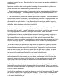
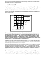
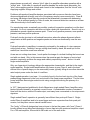
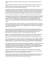
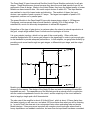
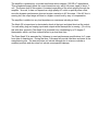
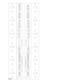
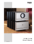
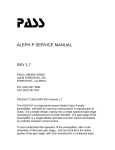
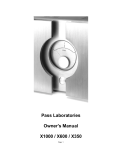
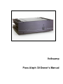
Volksamp
Pass Aleph 30 Owner's Manual
Dear Customer,
The Pass Aleph 30 is the first of the second generation of Aleph single-ended Class A power
amplifiers. This design results from my commitment to create the best sounding product, a
simple circuit having the most natural characteristic. The Pass Aleph 30 integrates power
Mosfet devices and pure single ended Class A operation in a simple two-gain-stage topology
with the sole purpose of recreating subjectively natural sound.
The Pass Aleph 30 is unique in a number of ways:
Most amplifiers on the market have between five and seven gain stages in series between the
input and the output. The Aleph 30 has but two, and enjoys a very direct path from input to
output, further enhancing the purity of the circuit and the resulting sound.
The output stage of the Aleph 30 is a unique blend of traditional design and innovation
addressing the unique requirements of loudspeakers. Previous methods of loading the output
stage have used networks consisting of resistors, coils, transformers, and active current
sources, all of which offer an optimal load line based on a resistive load. The Aleph 30 has a
current source topology which optimizes performance for a wide range of impedance and
reactance in the load, improving all aspects of performance into real loudspeakers. Pass
Labs has US patent No. 5710522 on this output stage topology.
The Aleph 30 is unique in that there are no adjustments of any kind in the circuitry. There are
no potentiometers to adjust. The operating parameters of bias currents and DC offset and so
on are defined by physical constants, and will not go out of adjustment.
Most important, the Aleph 30 brings improvement to the recreation of subjective sonic reality.
The amplifier delivers detail and subjective space rarely found in semiconductor circuits,
coupled with the authority and clarity rarely found in tube amplifiers.
The Pass Aleph 30’s ancestry lies in the highly praised Aleph 3. We have kept virtually all of
the circuit design and choice of parts intact.
The amplifier uses exactly the same circuit topology except that a balanced XLR input has
been provided in addition to the single-ended RCA input of the Aleph 3. The balanced input
circuitry is the same topology as the rest of the original Aleph series, accomplishing true high
performance balanced input without additional active components. It has been improved,
however, to offer a higher input impedance on the single-ended input, 47 Kohms. The original
Aleph 3 had a 23 Kohm input impedance, and the other Aleph amplifiers had a 10 Kohm
single-ended input impedance.
The input devices are slightly better than the originals, but significant improvement is to be
found in the manner of matching the input devices. Previously the input differential transistors
were merely matched to each other, but beginning with the Aleph 30 they are now matched
both to each other and to the rest of the amplifier circuit. We select the input devices as part
of the complete amplifier, swapping them in and out until the best performance is achieved.
Tweaking the input stage in this manner and with other adjustment techniques we have been
able to significantly lower the noise floor and improve the power supply noise rejection of the
amplifier. Typically the Aleph 30 has about 6 dB greater dynamic range compared to the
Aleph 3.
We have increased the number of output power Mosfet devices from four per channel to six.
These are the same devices as the original Aleph 3, and are matched in the same manner,
taken from the same lot codes and matched to about 2% Vgs. The greater number of devices
lowers the distortion and improves the damping factor by about 50%, and also allows us to run
the bias up a bit, giving higher heat sink temperatures but with the same on-chip
temperatures.
The power supply has been improved with half-again more power supply capacitors with twice
the voltage ratings, giving lower ESR figures. Also the power supply incorporates much
improved line noise filtering in both differential and common mode, which filters out incoming
noise and reduces noise emission by the amplifier.
One of the biggest differences in the Pass Aleph 30 is the type of chassis and heat sink used.
The Aleph 3 was machined entirely from aluminum extrusions stock. While this resulted in a
unique and very functional appearance, it had several drawbacks. First it was very expensive.
Also, it allowed very limited space for access to input and output terminals on the rear of the
amplifier, and required the on/off power switch to sit in the rear underneath the wiring. It has
been said that ownership of the original Alephs was proof of the owner’s dedication to sound
at the cost of convenience.
The Aleph 30 has a new, more conventional, chassis with heat sinks on the side, a faceplate
with a power switch, and a regular sheet metal type chassis. In addition to being more
convenient, this approach costs less, and we have passed the difference on to the customer.
The final result is that the Aleph 30 performs better than the original Aleph 3 in all areas, has
the additional feature of balanced inputs, and costs a lot less.
The Volksamp version of the Aleph 30 is produced under license from Nelson Pass and Pass
Laboratories Inc., and is distributed and serviced by Pass Labs Domestic Sales Inc. and Pass
Labs Foreign Sales Inc.
Thanks you for purchasing it. Enjoy.
Nelson Pass
( [email protected] )
Setup
The amplifier has four sets of connections and one switch: The first connection and switch is
the AC line power system. The amplifier's voltage and current rating are indicated on the
bottom. It will be either 240 volts, 120 volts, or 100 volts, all with a 3AG slow blow type fuse.
The frequency rating of the AC line source is 50 to 60 Hz.
Your amplifier is provided with a standard AC power cord which fits into the line receptacle
located just below the power switch. The amplifier is equipped for operation with an earth
ground provided by the AC outlet. Do not defeat this ground. The chassis of the amplifier is
connected directly to this earth ground, and the audio circuit ground is connected to the
chassis and earth through a power thermistor, which gives a ground safety connection but
helps avoid ground loops.
The second connection are the single-ended inputs, which occur through standard RCA
connectors. The input impedance of the amplifier is 47 K ohms, and is DC coupled, with no
capacitors.
The third connection are the balanced inputs, which occur through standard XLR connectors.
The balanced input impedance is 52 Kohms. Input pin 1 of the XLR connector is input
ground, pin 2 is the positive input, and pin 3 is the negative input. As shipped, there is a
shorting jumper between pins 1 and 3, which is the configuration for single-ended input.
This shorting jumper should be used when operating the amplifier with the RCA input,
otherwise you will not get the proper gain figure for the amplifier. If you operate the amplifier
with balanced inputs, you will remove this jumper, and we advise you to save it carefully for
future use.
The fourth connection is the amplifier output connection. Connect the 5-way output
connectors to loudspeaker plus and ground, using the cable of your choice.
The amplifier draws about 200 watts from the wall at all times, and during idle operation nearly
all of this energy will appear as heat on the heat sinks. Good ventilation is vital to the proper
operation of the amplifier. It has been adjusted for optimal performance at room temperature,
but will work well between 50 and 90 degrees Fahrenheit (10 to 33 Celsius). You should
leave at least six inches clearance on the sides and top. The amplifier should not be placed
in a closed cabinet which does not have forced air ventilation.
This amplifier runs hot. The heat sinks will warm up in about an hour to a temperature which
will not be comfortable to touch for more than a moment or two, which is 120 to 130 degrees
Fahrenheit (50 to 55 degrees Celsius). This is normal, and there is a thermal shut off system
which will shut down the amplifier at internal temperatures in excess of 160 deg. F. and 70
deg. C.
It takes about an hour of warm up time to get the best performance out of the amplifier. It will
take that long to reach operating temperature and exhibit lowest distortion and noise. This is
not a subjective judgement, but based on actual distortion and noise measurements. Many
customers have reported that longer warm up yields more improvement.
The amplifier does not require any maintenance. While the design is conservative, this is a
hard running amplifier, as single ended Class A operation is the least efficient operating
mode. In fifteen years the electrolytic power supply capacitors will get old. Depending on
usage, you will begin to have semiconductor and other failures between 10 and 50 years after
date of manufacture. Later, the sun will cool to a white dwarf, and after that the universe will
experience heat death.
Pass Product Philosophy and Design Theory
When I started designing amplifiers 25 years ago, solid state amplifiers had just achieved a
firm grasp on the market. Power and harmonic distortion numbers were king, and the largest
audio magazine said that amplifiers with the same specs sounded the same.
We have heard Triodes, Pentodes, Bipolar, VFET, Mosfet, TFET valves, IGBT, Hybrids, THD
distortion, IM distortion, TIM distortion, phase distortion, quantization, feedback, nested
feedback, no feedback, feed forward, Stasis, harmonic time alignment, high slew, Class AB,
Class A, Pure Class A, Class AA, Class A/AB, Class D, Class H, Constant bias, dynamic bias,
optical bias, Real Life Bias, Sustained Plateau Bias, big supplies, smart supplies, regulated
supplies, separate supplies, switching supplies, dynamic headroom, high current, balanced
inputs and balanced outputs.
Apart from digitally recorded source material, things have not changed very much in twenty
five years. Solid state amplifiers still dominate the market, the largest audio magazine still
doesn't hear the difference, and many audiophiles are still hanging on to their tubes. Leaving
aside the examples of marketing hype, we have a large number of attempts to improve the
sound of amplifiers, each attempting to address a hypothesized flaw in the performance.
Audiophiles have voted on the various designs with their pocketbooks, and products go down
in history as classics or are forgotten. The used market speaks eloquently: Marantz 9's
command a high price, while Dyna 120's are largely unwanted.
So far there has been a failure in the attempt to use specifications to characterize the
subtleties of sonic performance. Amplifiers with similar measurements are not equal, and
products with higher power, wider bandwidth, and lower distortion do not necessarily sound
better. Historically, that amplifier offering the most power, or the lowest IM distortion, or the
lowest THD, or the highest slew rate, or the lowest noise, has not become a classic or even
been more than a modest success.
For a long time there has been faith in the technical community that eventually some objective
analysis would reconcile critical listener's subjective experience with laboratory measurement.
Perhaps this will occur, but in the meantime, audiophiles largely reject bench specifications as
an indicator of audio quality. This is appropriate. Appreciation of audio is a subjective human
experience. We should no more let numbers define audio quality than we would let chemical
analysis be the arbiter of fine wines. Measurements can provide a measure of insight, but
are no substitute for human judgment.
As in art, classic audio components are the results of individual efforts and reflect a coherent
underlying philosophy. They make a subjective and an objective statement of quality which is
meant to be appreciated. It is essential that the circuitry of an audio component reflects a
philosophy which address the subjective nature of its performance first and foremost.
Lacking an ability to completely characterize performance in an objective manner, we should
take a step back from the resulting waveform and take into account the process by which it
has been achieved. The history of what has been done to the music is important and must be
considered a part of the result. Everything that has been done to the signal is embedded in it,
however subtly.
Experience correlating what sounds good to knowledge of component design yields some
general guidelines as to what will sound good and what will not:
1) Simplicity and a minimum number of components is a key element, and is well reflected in
the quality of tube designs. The fewer pieces in series with the signal path, the better. This
often true even if adding just one more gain stage will improve the measured specs.
2) The characteristic of gain devices and their specific use is important. Individual variations
in performance between like devices is important, as are differences in topological usage. All
signal bearing devices contribute to the degradation, but there are some different
characteristics are worth attention. Low order nonlinearities are largely additive in quality,
bringing false warmth and coloration, while abrupt high order nonlinearities are additive and
subtractive, adding harshness while losing information.
3) Maximum intrinsic linearity is desired. This is the performance of the gain stages before
feedback is applied. Experience suggests that feedback is a subtractive process; it removes
information from the signal. In many older designs, poor intrinsic linearity has been corrected
out by large application of feedback, resulting in loss of warmth, space, and detail.
High idle current, or bias, is very desirable as a means of maximizing linearity, and gives an
effect which is not only easily measured, but easily demonstrated: Take a Class A or other
high bias amplifier and compare the sound with full bias and with bias reduced. (Bias
adjustment is easily accomplished, as virtually every amplifier has a bias adjustment pot, but it
should be done very carefully). As an experiment it has the virtue of only changing the bias
and the expectations of the experimenter.
As the bias is reduced the perception of stage depth and ambiance will generally decrease.
This perception of depth is influenced by the raw quantity of bias current. If you continue to
increase the bias current far beyond the operating point, it appears that improvements are
made with bias currents which are much greater than the signal level. Typically the levels
involved in most critical listening are only a few watts, but an amplifier biased for ten times
that amount will generally sound better than one biased for the few watts.
For this reason, designs which operate in what has been referred to as "pure" Class A are
preferred because their bias currents are much larger than the signal most of the time. As
mentioned, preamp gain stages and the front ends of power amplifiers are routinely single
ended "pure" Class A, and because the signal levels are at small fractions of a watt, the
efficiency of the circuit is not important.
4) Given the assumption that every process that we perform on the signal will be heard, the
finest amplifiers must employ those processes which are most natural. There is one element
in the chain which we cannot alter or improve upon, and that is the air. Air defines sound, and
serves as a natural benchmark.
Virtually all the amplifiers on the market are based on a push-pull symmetry model. The pushpull symmetry topology has no particular basis in nature. Is it valid to use air's characteristic
as a model for designing an amplifier? If you accept that all processing leaves its signature
on the music, the answer is yes.
One of the most interesting characteristics of air is its single ended nature. Sound traveling
through air is the result of the gas equation
PV1.4 = 1.26 X 10⁴
where P is pressure and V is volume, and whose curve is illustrated in fig. 1. The small
nonlinearity which is the result of air's characteristic is not generally judged to be significant at
normal sound levels, and is comparable to the distortion numbers of fine amplifiers. This
distortion generally only becomes a concern in the throats of horns, where the intense
pressure levels are many times those at the mouth, and where the harmonic component can
reach several per cent.
1.4
1.2
1.0
.8
.6
PRESSURE
(bars)
1.4
1.2
1.0
.8
.6
VOLUME
(M 3/Kg)
FIG 1
CHARACTERISTIC OF AIR
Fig. 1 shows the single ended nature of air. We can push on it and raise the pressure an
arbitrary amount, but we cannot pull on it. We can only let it relax and fill a space as it will;
the pressure will never go below "0". As we push on air, the increase in pressure is greater
than the corresponding decrease when we allow air to expand. This means that for a given
motion of a diaphragm acting on air, the positive pressure perturbations will be slightly greater
than the negative. From this we see that air is phase sensitive.
As a result of its single ended nature, the harmonic content of air is primarily 2nd order, that is
to say most of the distortion of a single tone is second harmonic. The phase of this distortion
reflects the higher positive pressure over the negative.
Air's transfer curve also shows also that it is monotonic, which is to say its distortion products
decrease smoothly as the acoustic level decreases. This is an important element that has
often been overlooked in audio design and is reflected in the poor quality of early solid state
amplifiers and D/A and A/D converters. They are not monotonic: the distortion increases as
the level decreases.
The usual electrical picture of an audio signal is as an AC waveform, without a DC
component. Audio is represented as alternating voltage and current, where positive voltage
and current alternates with negative in a reciprocal and symmetric fashion. This fiction is
convenient because it lends itself to the use of an energy efficient design for amplifier power
stages known as push-pull, where a "plus" side of an amplifier alternates operation with a
"minus" side. Each side of a push-pull amplifier handles the audio signal alternately; the
"plus" side supplying positive voltage and current to the loudspeaker, and the "minus" side
supplying negative voltage and current.
Problems with push-pull amplifier designs associated with crossover distortion have been
discussed elsewhere at length, and one of the primary results is non-monotonicity. Class B
and many AB designs have distortion products that dramatically increase with decreasing
signal. This is reduced greatly by Class A mode, but crossover distortion remains as a lower
order discontinuity in the transfer curve.
For reproducing music as naturally as possible, push-pull symmetric operation is not the best
approach. Air is not symmetric and does not have a push-pull characteristic. Sound in air is a
perturbation around a positive pressure point. There is only positive pressure, more positive
pressure, and less positive pressure.
Push-pull circuits give rise to odd ordered harmonics, where the phase alignment reflects
compression at both positive and negative peaks and crossover nonlinearity near the zero
point.
Push-pull operation in amplifiers is commonly portrayed by the analogy of a two-man saw
cutting down a tree. Certainly if we are cutting down trees by hand, we would opt for this
method, as it would be much more efficient.
As we are not cutting down trees, I much prefer the image of a violinist holding the bow at one
end with one hand. Only in this manner does the musician gain the degree of control and
precision required to produce the range and subtlety required by music. And so it is with
single-ended amplifiers.
Only one linear circuit topology delivers the appropriate characteristic, and that is the single
ended amplifier. Single ended amplification only comes in pure Class A, and is the least
efficient form of power stage you can reasonably create, typically idling at more than twice the
rated output power under the best of conditions.
Single ended operation is not new. It is routinely found in the low level circuitry of the finest
preamplifying stages and in the front end circuits of the finest power amplifiers. The first tube
power amplifiers were single ended circuits using a single tube driving the primary of a
transformer.
In 1977 I designed and published in Audio Magazine a single ended Class A amplifier using
bipolar followers biased by a constant current source. A considerable number of amateurs
have built the device, rated at 20 watts output, and many have commented on its unique sonic
signature.
Single ended Class A operation is generally less efficient than push-pull Class A. Single
ended Class A amplifiers tend to be even bigger and more expensive than their push-pull
cousins, but they have a more natural transfer curve.
The "purity" of Class A designs has been at issue in the last few years, with "pure" Class A
loosely defined as an idling heat dissipation of more than twice the maximum amplifier output.
For a 100 watt amplifier, this would be 200 watts out of the wall at idle.
As the Pass Aleph 30 idles at four times its rated output, I think we can safely think of it as
“pure”.
Designs that vary the bias against the musical signal will generally have bias currents at or
below the signal level. This is certainly an improvement from the viewpoint of energy
efficiency, but the sound reflects the lesser bias point.
I authored the first patent on the dynamically biased Class A amplifier in 1974, however I have
not used the technique for the last 15 years. The reason is that I found the quality of sound
associated with an efficient Class A operating mode inferior in depth and less liquid at high
frequencies, simply because it operates at reduced bias at low levels. Given the plethora of
cool running “Class A” amplifiers on the market, you might say I opened a Pandora’s box.
A very important consideration in attempting to create an amplifier with a natural characteristic
is the selection of the gain devices. A single ended Class A topology is appropriate, and we
want a characteristic where the positive amplitude is very, very slightly greater than the
negative. For a current gain device, that would mean gain that smoothly increases with
current, and for a tube or field effect device a transconductance that smoothly increases with
current.
Triodes and Mosfets share a useful characteristic: their transconductance tends to increase
with current. Bipolar power devices have a slight gain increase until they hit about an amp or
so, and then they decline at higher currents. In general the use of bipolar in a single ended
Class A circuit is a poor fit.
Another performance advantage shared by Tubes and Fets is the high performance they
deliver in simple Class A circuits. Bipolar designs on the market have between five and seven
gain stages associated with the signal path, but with tubes and Mosfets good objective
specifications are achievable with only 2 or 3 gain devices in the signal path.
Readers of The Audio Amateur Magazine will be familiar with my “Zen” design, which uses a
Mosfet in a power amplifier which has only one gain stage, and only one gain transistor.
Research continues at Pass Labs in improving the performance of very simple gain circuits.
Yet a third advantage tubes and Mosfets have over bipolar devices is their greater reliability at
higher temperatures. As noted, single ended power amplifiers dissipate comparatively high
wattages and run hot. Bipolar devices are much more prone to failure at high temperatures.
In a decision between Triodes and Mosfets, the Mosfet's advantage is in naturally operating at
the voltages and currents we want to deliver to a loudspeaker. Efforts to create a direct
coupled single ended triode power amplifier have been severely limited by the high voltages
and low plate currents that are the province of tubes. The commercial offerings have not
exceeded 8 watts or so, in spite of hundreds of dissipated watts.
Transformer coupled single ended triode amplifiers are the alternative, using very large
gapped-core transformers to avoid core saturation from the high DC current, but they suffer
the characteristic of such a loosely coupled transformer as well.
The promise of the transconductance characteristic in power amplifiers in providing the most
realistic amplified representation of music is best fulfilled in Mosfet single ended Class A
circuitry where it can be used very simply and biased very high.
The Pass Aleph 30 uses International Rectifier Hexfet Power Mosfets exclusively for all gain
stages. These Mosfets were chosen because they have the most ideal transfer curve for an
asymmetric Class A design. Made in the United States, they have the highest quality of power
Mosfets we have tested to date. We match output devices to within 2%. The input devices
are matched in circuit for lowest noise and distortion. The smallest of these, the input
devices, are capable of peak currents of 5 amps. The largest are capable of peaks of 25
amps each, and are run in parallel pairs.
The power Mosfets in the Pass Aleph 30 have chip temperatures ratings to 150 degrees
Centigrade, and we operate them at small fractions, typically 20% of their ratings. For
extended life, we do not allow chip temperatures to exceed 85 degrees C.
Regardless of the type of gain device, in systems where the utmost in natural reproduction is
the goal, simple single ended Class A circuits are the topologies of choice.
It is a very simple topology, which is a key part of the sound quality. Other solid state
amplifier designs have five to seven gain stages in the signal path in order to get enough gain
to use feedback to provide adequate performance. In this amplifier, we get greater linearity by
providing much more bias through two gain stages: a differential input stage, and the output
transistors.
Mosfets provide the widest bandwidth of solid state power devices, however they were not
chosen for this reason. The design of the Aleph 30 does not seek to maximize the amplifier
bandwidth as such. The capacitances of the Mosfets provide a natural rolloff in conjunction
with the resistive impedances found in the circuit, and the simplicity of the circuit allows for
what is largely a single pole rolloff characteristic.
The slew rate of the amplifier is about 40 Volts/uS load , which is about 10 times faster than
the fastest signal you will ever see, and about 100 times faster than what you will be listening
to. In and of itself, the slew rate is an unimportant factor when evaluating tube and simple
Mosfet designs. It becomes more important with complex circuit topologies where there is
heavy dependence on feedback correction, but even then its importance has been overstated.
The amplifier is powered by a toroidal transformer which charges 120,000 uF capacitance.
This unregulated supply feeds the output transistors only with a full power ripple of about .3
volt. The power draw of this system is constant regardless of the music playing through the
amplifier. As such, it does not depend on a high quality AC outlet or special power cords,
since the dynamic performance does not create a variation in AC line draw. If the AC line is
running low, the output stage will bias to a higher current level by way of compensation.
The amplifier is stable into any load impedance or reactance including a direct.
The Aleph 30 is impervious to electrostatic shock at the input and dead shorts at the output.
You can safely plug and unplug inputs and outputs while the amplifier is running. (Do not try
this with other products).The Aleph 30 is protected from overheating by a 75 degree C.
thermostatic switch, and from internal failure by a slow-blow fuse.
The Pass Aleph 30 is warranted by Volksamp to meet performance specifications for 3 years
from date of manufacture. During that time, Volksamp will provide free labor and parts at the
manufacturing site. The warranty does not include damage due to misuse or abuse or
modified products and also does not include consequential damage.
SPECIFICATIONS
Gain
20 dB balanced, 26 dB single ended
Freq. Response
- 0.5 dB @ 2 Hz, -1.5 dB @ 100 KHz
Power Output
30 watts/ch @ 8 ohms, 40 watts @ 4 ohms
Maximum Output
25 volts, 5 amps
Distortion (1KHz)
0.2%
Input Impedance
47 Kohm single-ended, 52 Kohm differential
Damping factor
100
Crosstalk
> -80 dB
@ 30 watts, 8 ohms
20-20 KHz
Balanced Input Rejection -50 dB typical CMRR
Output Noise
< 500 uV unweighted
Random noise floor
5 uV typical
DC offset
< 100 mv
Power Consumption
200 watts
Temperature
25 degrees C. above ambient
Dimensions
17 " W x 15.5" D x 5.5" H
Shipping Weight
45 lb.
VOLKSAMP
Pass Labs
Po Box 219
Foresthill CA 95631
tel
fax
(530) 367 4935
(530) 367 4984
www.volksamp.com
www.passlabs.com
Pass Aleph 30 Service Information.
The Pass Aleph 30 has only two gain stages which are biased by current sources. Because
of the inherent simplicity of the circuit, it is easy to understand and repair. There are no
adjustments.
Figure 1 shows the simplified schematic of the amplifier. Two p channel Mosfets form an input
differential pair biased by a current source operating at about 20 ma. The drain of the input
Mosfet is attached to the gate of an n channel power Mosfet which forms the active output
stage. It is biased by a current source at slightly less than 2 amps.
The voltage rails of the supply are at 25 volts, and each channel draws approximately 100
watts.
Figure 2 shows the actual schematic for the power supply and one channel.
F1 is a slow blow fuse, set at 4 amps for 100-120 volt operation, and 2 amps for 220-240 volt
operation.
S1 is the power switch, which has two sets of 25 amp contacts wire in parallel.
T1 is a thermostatic switch rated at 75 degrees Centigrade. It is mounted to the rear heat
sink.
TH1 is a power thermistor used to connect the circuit and chassis ground to the AC outlet
ground. It will normally operate at 5 ohms, suppressing ground loops in the system, but will
drop to a low impedance if significant current is passed through it.
The power transformer drives a high current bridge and 120,000 uF of capacitance to form a
plus and minus 25 volt supply.
Referring to the channel itself, Q1 and Q2 form the differential input pair of Mosfets. They are
biased by the current source formed by Q3. Q3 is biased to about 25 ma by the reference
Zener diode Z5 which sets about 5 volts across R11.
Z1 – Z4 protect the input from static spikes. R2, 3, 4, 5, 6, 7 form the input networks and
feedback loops.
The output of the differential input paid drives the gates of output devices Q9 - 11. These
parallel devices are matched as close as .01 volts, however variations as high as .1 volts will
not impede operation.
The voltage across R14 shows the drive voltage for the output stage, and it should have 4-5
volts across it.
The output of the amplifier is taken from the drains of Q9 - 11. Q9 - 11 are provided a bias
current by the current source circuitry of Q6 - 8, also matched N channel Mosfets.
Q6 - 8 are set at 2 amps DC by the network consisting of Q5 and the components surrounding
it. Q5 is biased by R17 and R18 in series. A capacitor C9 is used to reduce supply noise.
R20 serves to sense the current running through Q6, and feeds that to the base of Q5,
forming a loop that holds the output current at 2 amps. The PN junction drop of Q5 forms the
reference voltage for the system.
R19 is a fixed resistor which trims the DC current value. R21 and C10 adjust the current
against output current as sensed by the voltage across R34.
Fig. 3 and 4 shows the AC voltage wiring and component layout of the central power supply
board. This board holds the power supply components.
On Fig 3 you can see the wiring arrangements for the various AC line voltages: 100, 120, and
240 volts.
Fig 5 shows the component layout of the board assemblies forming the two channels (left and
right) of the amplifier.
There are no adjustments to the amplifier. Values for biasing various components are taken
from physical constants, such as PN junctions and Zener voltages, and through matching of
Mosfet transistors.
The input Mosfets are matched in the working amplifier, and the output Mosfets are in
matched pairs within .1 volt, although production tolerance is typically .01 volt. The Vgs
figures for the output devices are written on the top of the package of each.
For a 120 volts AC line, the amplifier will draw about 2 amps RMS. If you measure current
draw with an averaging meter, you will get a smaller number.
The amplifier is designed so that the heat sinks will operate approximately 25 degrees C.
above ambient, for a typical temperature of 50 degrees C. Temperature protection occurs at
75 degrees C.
The amplifier will not be damaged by driving a short circuit, and it is probable that the only
failures you will see will be random component failure.
VOLKSAMP
Pass Labs
Po Box 219
Foresthill CA 95631
tel
fax
(530) 367 4935
(530) 367 4984
www.volksamp.com
www.passlabs.com