1
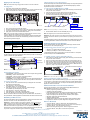
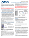
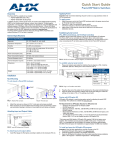
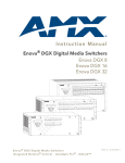
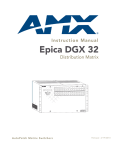
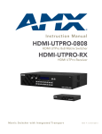
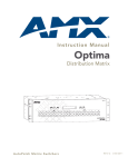
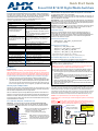
Quick Start Guide
Enova DGX 8/16/32 Digital Media Switchers
Overview and General Specifications
Enova DGX 8/16/32 Digital Media Switchers are available in various configurations in
increments of four up to 8x8, 16x16, and 32x32 respectively. Therefore, the illustrations
may differ from the model(s) purchased. The Instruction Manual – Enova DGX 8/16/32
Digital Media Switchers contains complete documentation (including board
specifications and supported resolutions); see www.amx.com. Each enclosure
contains an integrated NetLinx Central Control Processor.
General Specifications
Approvals
AC Power
CE, UL, cUL, FCC Class A, RoHS
100 VAC to 240 VAC single phase
50 Hz to 60 Hz
DGX 8 / DGX 16:
Power Consumption
• Max 977 Watts w/redundancy; 1954 Watts w/out
Note: For specifications for power
DGX 8: Typical 145 Watts, fully loaded enclosure
consumption with DXLink power,
DGX 16: Typical 362 Watts, fully loaded enclosure
see the Instruction Manual.
DGX 32:
• Max 1379 Watts w/redundancy; 2758 Watts w/out
• Typical 585 Watts, fully loaded enclosure
Thermal Dissipation
DGX 8 / DGX 16:
• Max 3334 BTU/hr. w/redundancy; 6667 w/out
Note: For specifications for thermal
DGX 8: Typical 495 BTU/hr., fully loaded enclosure
dissipation with DXLink power, see the
DGX 16: Typical 1235 BTU/hr., fully loaded encl.
Instruction Manual.
DGX 32:
• Max 4705 BTU/hr. w/redundancy; 9410 w/out
• Typical 1996 BTU/hr., fully loaded encl.
Operational Temperature
32° F to 104° F (0° C to 40° C)
Storage Temperature
-22° F to 158° F (-30° C to 70° C)
Storage Humidity/Operational Humidity 0% to 90% RH / 5% to 85% RH (non-condensing)
Compatible Modules / Wallplates
DXLink Transmitters / Receiver / Wallplate TXs
DGX Fiber Transmitters / Receivers
Enova DGX 8/16
Enova DGX 32
MTBF: 168,000 hrs.
MTBF: 92,000 hrs.
Depth:15 in. (38.1 cm)
Depth: 20.08 in. (51 cm)
16 in. (40.64 cm) with extractors
21.08 in. (53.54 cm) with extractors
Width: 19.0 in. (48.26 cm) with rack
Width: 19.0 in. (48.26 cm) with rack mounting ears
mounting ears
Height: 6.84 in. (17.37 cm) 4 RU
Height: 10.45 in. (26.54 cm) 6 RU
Weight: Approx. 35 lbs/55 lbs (15.9 kg / Weight: Approximately 73 lbs (33.1 kg) per loaded
24.95 kg) per loaded enclosure
enclosure
Shipping Weight: Approx. 45 lbs/65 lbs Shipping Weight: Approximately 83 lbs
(20.4 kg /29.5 kg) per loaded enclosure (37.6 kg) per loaded enclosure
HDMI Boards (HDCP 1.4) – Inputs and outputs incorporate HDMI® technology.
HDMI connectors route high-resolution HDMI or DVI signals with or without HDCP.
For single-link DVI signals, use a cable adapter.
DVI Boards (HDCP 1.4) – Inputs and outputs are HDMI compatible. DVI output pin 14
(+5 VDC out) supplies 50 mA per each of the four output connectors. By changing the
EDID, DVI Boards can route HDMI.
DXLink Boards – Inputs and outputs incorporate HDMI technology. Use with DXLink
Transmitters / Receivers, which automatically adjust the scaling and image and almost
always result in a quality image on the monitor. If the setup has special requirements
or adjustment is needed, see the Instruction Manual.
Important: DIP switches must be set on the DXLink Transmitters and Receiver before
units are cabled to the switcher via its DXLink Boards. For information on DXLink
modules or wallplates, see the applicable Quick Start Guide.
Audio EDID Settings
HDMI, DVI, and DXLink Boards ship with a basic audio EDID configuration. To
optimize audio for your system, you may need to replace default EDID settings.
Custom EDID files and DGX Configuration Software are available at www.amx.com.
For information, see the Instruction Manual – Enova DGX 8/16/32 Digital Media
Switchers or the software’s Help file.
DGX Board Default EDID Files
•
•
HDMI and DXLink – AMX_HDMI1_A2_basicAudio.edid1
DVI – AMX_DVI1_A0.edid1
DGX Board Custom EDID Files
•
•
•
•
1
2
1080p (VIC 16) – AMX_HDMI1_A1.edid2
1080p (VIC 16) – AMX_HDMI1_A1_basicAudio.edid1
720p (VIC 4) – AMX_HDMI1_A1_720p.edid2
720p (VIC 4) – AMX_HDMI1_A1_720p_basicAudio.edid1
- Supports basic audio only (L-PCM 32 k, 44.1 k, and 48 k)
- Supports up to 192 k for L-PCM, 48 kHz Dolby (5.1), and 48 kHz DTS (5.1)
Epica DGX SC Optical Boards – SC Fiber Connectors
Epica DGX SC Optical Boards are compatible in Enova DGX Switchers.
Safety Recommendations for Laser Products
Important: No user serviceable parts are inside an Enova DGX enclosure; service
should only be done by qualified personnel.
Warning: Use of controls or adjustments or performance of procedures other than
those specified herein may result in hazardous radiation exposure.
Installation
Rack Mounting
Caution: To prevent overheating, avoid placing high heat-producing equipment
directly above/below enclosure. The system requires a minimum of 1 empty rack unit
above and below (3 empty rack units are recommended). Verify that the openings on
the sides and top of the enclosure are not blocked and do not have restricted airflow.
To rack mount an enclosure (Enova DGX 32 requires a minimum of 2 people):
1. Position the enclosure in the rack and secure it with rack mounting screws.
2. Provided / recommended for SC Optical Boards – Install cable management bars:
(A) Enova DGX 32 only – Remove number plate at rear top. (B) Fasten bar with
two screws on one end of the board and one screw at the other (the long part of
the bar is to the right of holes); do not over tighten. (C) Replace the number plate.
Attaching Input and Output Cables
Generally, any input board in an Enova DGX Switcher can route signals to any type of
output board; the signal format is automatically converted to match the output board.
Note that DGX SC Optical Boards do not support HDCP.
DXLink™ Twisted Pair Input and Output Boards require DXLink™ Transmitters and
Receivers. SC Optical Input and Output Boards require DGX Fiber Transmitters and
Receivers. For details, see each product’s Quick Start Guide or Instruction Manual.
For testing purposes, attach just the first two source and destination devices (and any
required transmitters or receivers).
Enova DGX AIE, HDMI, DVI, and DXLink Boards
AIE Boards – These boards are documented separately. Before wiring audio,
the AIE boards must be uninstalled, have their DIP switches set, and be reinstalled.
For directions, see the Quick Start Guide - Enova DGX Audio Insert/Extract Board.
Note: The Instruction Manual contains information on:
• InstaGate Pro Technology (easy switching of
HDCP protected content) for HDMI.
• Software for scaling and EDID programming.
HDMI Board
DVI Board
DXLink Board
AIE Board
FIG. 1 HDMI, DVI, DXLink, and AIE Boards
Note: System setup for DXLink Boards is
similar to FIG. 2, only with DXLink TXs and
RXs installed between the DXLink Boards
and the source and destination devices.
Exercise caution to avoid direct eye exposure to invisible laser radiation. Follow the
recommendations below whenever installing or working with DGX fiber products.
• Be sure to apply the power only after all fiber connections are made and no fiber
ends are exposed.
• Do not remove dust plugs from SC fiber connectors or the dust caps from the
fiber cables until establishing connections; avoid direct eye exposure.
• Make sure all cables, including fiber cables, are correctly connected and/or
terminated.
• Before you unplug a fiber cable on an input board, disconnect the power on the
DGX TX that is connected to the input.
• Before you unplug a fiber cable on an output board, disconnect the switch for
that output connector.
Each board has four SC fiber connectors (remove plug to attach cable). These boards
are used in conjunction with DGX Fiber TX and RX Modules. Signals routed through
these boards normally do not require any adjustment, as the DGX Fiber Modules
automatically scale and adjust the signal as necessary. Set up the modules according
to their Quick Start Guide, installing a TX between each input board and the source
device and an RX between each output board and the destination device (FIG. 2).
Caution: For SC Optical Boards, we recommend using the provided cable
management bars or some other type of cable management system to avoid damage
to fiber cables.
Caution: Do not severely bend or kink the fiber cable. Irreversible damage can occur.
Refer to the physical limitations (bend radius) specified for the cable by manufacturer.
The bend radius for AMX SC terminated fiber cables is 2 inches (5 cm).
SC fiber connector
(make sure it seats firmly;
normally a click is heard)
CLASS 1 LASER PRODUCT.
CAUTION – CLASS 3R
INVISIBLE RADIATION WHEN
OPEN; AVOID DIRECT EYE
EXPOSURE.
System Setup
DGX TX
DGX RX
Enova DGX Switcher
SC Optical Input
SC Optical Output
FIG. 2 SC fiber cable attached to output; system setup with DGX Fiber TX and RX Modules
Applying Power and Startup
Cable Requirements for the LAN Connection
Note: We recommend using a surge protector and/or an AC line conditioner.
To apply power:
Connect the LAN port on the Enova DGX Switcher directly to a LAN (network) with an
RJ-45 cable (crossover or straight-through; port automatically adjusts). A DHCP
capable server must be in the network.
1.
2.
1.
Plug power cords into both power receptacles.
Plug the other ends of the power cords into a power strip (we recommend using
a 20 A circuit breaker on a 110 circuit for fully loaded enclosures).
To connect an Enova DGX Switcher to a LAN:
If the system is not already powered, apply power according to the directions at
the top of the column to the left.
Insert one end of an RJ-45 link cable into the LAN 100/1000 port.
Connect the other end of the RJ-45 link cable to a LAN hub or switch.
The network will automatically assign a DHCP IP address.
2.
3.
LAN 100/1000 LEDs
Power cord
Power indicators
FIG. 3 Power cords plugged into receptacles (power supplies for Enova DGX 8/16 shown)
3. Turn on the power strip and wait 30 seconds.
4. Check the Indicator LEDs on front and rear of the enclosure; see the table below.
5. For systems with boards that require modules – Apply power to the modules.
6. Apply power to the source and destination devices.
Note: If only one power supply is working, the Power indicator on the front of the
enclosure will illuminate red (check the power connections).
If indicator lights do not respond with a normal display as stated in the table below,
check power connections and see the troubleshooting information in the manual
before contacting technical support.
Indicator LEDs – Normal Display on Power Up
Front Panel
Power – power status
Green (when both power supplies are working)
AC power
Green
Power Supplies
(DC is Tri-color)
• DC power
• Temperature
• Fault status
Green (amber = over temperature; red = fault state)
CPU
Status – system status
• Green during boot up (depending on load,
approximately 10 to 30 seconds)
• Blinking green at 1 second intervals when ready
To LAN
Program port
MAC address
LAN 100/1000 (RJ-45) port
L/A LED (green):
Active connection
SPD LED (yellow):
Receiving/transmitting LAN data
FIG. 5 LAN 100/1000 (RJ-45) port and Indicator LEDs
4.
Check indicator LEDs for the LAN 100/1000 port (FIG. 5).
Note: The Program port is used for NetLinx Studio setup.
Important: The RJ-45 connectors on the far left of the CPU should only be used to
connect to autonomous devices to prevent network loops (linking of enclosures is not
allowed).
For additional details on setup of the NetLinx Master via the WebConsole and control
via the integrated NetLinx Central Control Processor, see the Instruction Manual.
Establishing Serial Control (if applicable)
An Enova DGX Switcher can also be controlled by attaching an external control
device/system to the Control (RS-232) port.
PC Requirements for BCS commands* via a terminal emulation program:
•
•
Windows 7®or Windows XP Professional®
Serial port (or USB port – see the Instruction Manual)
Executing a Test Switch with the Control Panel
* Complete BCS information can be found in the Instruction Manual – BCS (Basic
Control Structure) Protocol at www.amx.com.
The Enova DGX Control Panel (standard on all enclosures) is used for controlling the
system’s switches and system attributes.
Power Indicator
To establish external control from RS-232 serial port:
LCD
Input Keys
Control Dial
Output Keys
Function Key
Cancel Key
1.
If the system is not already powered, apply power according to the directions at
the top of the column to the left.
Plug the null modem serial cable into the serial port on the enclosure (FIG. 6).
Plug the other cable end into the serial port on the serial controller/device (PC).
Open the serial communication software and set the port settings on the PC to
match the Enova DGX Switcher default settings (baud rate = 9600, data bits = 8,
stop bit = 1, parity = none, and flow control = none).
2.
3.
4.
Select Key
Take Key
Null modem serial cable and pinout
FIG. 4 Front view with control panel (Enova DGX 16 shown)
Control Panel Keys and Dial
•
•
•
•
•
Function Key – Press for start of the Function menu anytime during operation.
Select Key – Press to enter selections.
Cancel Key – Press to cancel an incomplete operation.
Take Key – Press to complete an operation.
Control Dial – Turn to scroll through the Function menu (starts with Change for
switching). After scrolling past the last item, menu loops back to the first item.
To execute a test switch:
1.
From the Function menu, locate Disconnect by scrolling with the Control Dial
and then press the Select Key.
2. Press Input Key 1; press the Take Key.
The default switch of 1 to all is disconnected.
3. Press the Function Key; press the Select Key to select Change.
The available Input and Output Keys turn blue.
4. Press Input Key 1. Input Key 1 flashes white.
5. Press Output Key 1. Output Key 1 illuminates white.
6. Press the Take Key to execute the switch. Both keys turn blue.
After the test switch, attach the remaining sources and destinations. For DXLink or
SC Optical Boards, install appropriate modules between the boards and the devices.
Establishing a LAN Connection
The Enova DGX Switcher has an integrated NetLinx Central Control Processor with
the server connection via the LAN 100/1000 port on the CPU.
Important: (1) The Enova DGX 32 uses DHCP by default. (2) Do not connect the
LAN 100/1000 port on the Enova DGX Switcher directly to a PC. It will not work.
Note: If an HDCP signal is switched from an HDMI, DVI, or DXLink Input Board to a
destination which does not support HDCP or to an SC Optical Output Board (no
HDCP support), a dark red image displays indicating authentication failure (the image
may also be orange when an HDCP signal is switched via DXLink).
FIG. 6 Null modem serial cable connected to Control (DB-9) serial port
External Serial Control via BCS – Test Switch
BCS Commands – Open terminal emulation program on PC. When power is applied
to the enclosure, a short splash screen appears. Enter DI1T (clears default switch of
1 to all). Enter CI1O2T (routes Input 1 to Output 2 on default level). When CI1O2T
appears, the switch is successful.
Additional Information Covered in Instruction Manual
See the Instruction Manual – Enova DGX 8/16/32 Digital Media Switchers at
www.amx.com for information on the following:
• NetLinx programming and firmware upgrades
• Complete control panel operation
• DGX Configuration Software with Scaler and EDID Programmer functionality,
a terminal emulation view, and the ability to enable or disable HDCP
• Setup for complete power redundancy with redundant power supplies
• Managing configuration files with XNConnect
• Adding or replacing boards
• APDiagnostics software (monitors and displays advanced diagnostic data)
• Programmer’s interface for system diagnostics; DGX_SHELL commands
Reference Documents
•
•
•
•
•
Instruction Manual – DXLink™ Twisted Pair Transmitters/Receiver
Cabling for Success with DXLink (on DXLink product pages under White Papers)
Instruction Manual – DGX Transmitters & Receivers
WebConsole & Programming Guide – NetLinx Integrated Controllers
Instruction Manual – BCS (Basic Control Structure) Protocol
For warranty information, see www.amx.com.
09/2013
©2013 AMX. All rights reserved. AMX and the AMX logo are registered trademarks of AMX.
AMX reserves the right to alter specifications without notice at any time.
3000 RESEARCH DRIVE, RICHARDSON, TX 75082 • 800.222.0193 • fax 469.624.7153 • technical support 800.932.6993 • www.amx.com
93-1058-001
REV: F