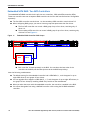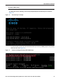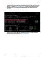
1
Spec Sheet
Cisco UCS C240 M4
High-Density
Rack Server (Small Form
Factor Disk Drive Model)
CISCO SYSTEMS
170 WEST TASMAN DR.
SAN JOSE, CA, 95134
WWW.CISCO.COM
PUBLICATION HISTORY
REV A.8
OCTOBER 15, 2014
CONTENTS
OVERVIEW . . . . . . . . . . . . . . . . . . . . . . . . . . . . . . . . . . . . . . . . . . . . . . . 5
DETAILED VIEWS . . . . . . . . . . . . . . . . . . . . . . . . . . . . . . . . . . . . . . . . . . . 6
Chassis Front View . . . . . . . . . . . . . . . . . . . . . . . . . . . . . . . . . . . . . . . . . . . . . . . . . . .6
Chassis Rear View . . . . . . . . . . . . . . . . . . . . . . . . . . . . . . . . . . . . . . . . . . . . . . . . . . .9
BASE SERVER STANDARD CAPABILITIES and FEATURES . . . . . . . . . . . . . . . . 10
CONFIGURING the SERVER . . . . . . . . . . . . . . . . . . . . . . . . . . . . . . . . . . . 14
STEP
STEP
STEP
STEP
STEP
STEP
STEP
STEP
STEP
STEP
STEP
STEP
STEP
STEP
STEP
STEP
STEP
1 VERIFY SERVER SKU . . . . . . . . . . . . . . . . . . . . . . . . . . . . . . . . . . . . . . . . . . . 15
2 SELECT RISER CARDS (OPTIONAL) . . . . . . . . . . . . . . . . . . . . . . . . . . . . . . . . . . 16
3 SELECT CPU(s) . . . . . . . . . . . . . . . . . . . . . . . . . . . . . . . . . . . . . . . . . . . . . . 17
4 SELECT MEMORY . . . . . . . . . . . . . . . . . . . . . . . . . . . . . . . . . . . . . . . . . . . . . 19
5 SELECT RAID CONFIGURATION . . . . . . . . . . . . . . . . . . . . . . . . . . . . . . . . . . . . 24
6 SELECT HARD DISK DRIVES (HDDs) or SOLID STATE DRIVES (SSDs) . . . . . . . . . . . . . 30
7 SELECT PCIe OPTION CARD(s) . . . . . . . . . . . . . . . . . . . . . . . . . . . . . . . . . . . . 34
8 ORDER OPTIONAL NETWORK CARD ACCESSORIES . . . . . . . . . . . . . . . . . . . . . . . . 38
9 ORDER GPU CARDS(OPTIONAL) . . . . . . . . . . . . . . . . . . . . . . . . . . . . . . . . . . . 42
10 ORDER POWER SUPPLY . . . . . . . . . . . . . . . . . . . . . . . . . . . . . . . . . . . . . . . . 44
11 SELECT AC POWER CORD(s) . . . . . . . . . . . . . . . . . . . . . . . . . . . . . . . . . . . . . 45
12 ORDER RAIL KIT AND OPTIONAL REVERSIBLE CABLE MANAGEMENT ARM . . . . . . . . 48
13 ORDER A TRUSTED PLATFORM MODULE (OPTIONAL) . . . . . . . . . . . . . . . . . . . . . 49
14 ORDER CISCO FLEXIBLE FLASH SD CARD MODULE (OPTIONAL) . . . . . . . . . . . . . . . 50
15 SELECT OPERATING SYSTEM AND VALUE-ADDED SOFTWARE . . . . . . . . . . . . . . . . 51
16 SELECT OPERATING SYSTEM MEDIA KIT . . . . . . . . . . . . . . . . . . . . . . . . . . . . . 54
17 SELECT SERVICE and SUPPORT LEVEL . . . . . . . . . . . . . . . . . . . . . . . . . . . . . . 55
OPTIONAL STEP - ORDER RACK(s) . . . . . . . . . . . . . . . . . . . . . . . . . . . . . . 60
OPTIONAL STEP - ORDER PDU . . . . . . . . . . . . . . . . . . . . . . . . . . . . . . . . . 61
SUPPLEMENTAL MATERIAL . . . . . . . . . . . . . . . . . . . . . . . . . . . . . . . . . . . 62
CHASSIS . . . . . . . . . . . . . . . . . . . . . . . . . . . . . . . . . . . . . . . . . . . . . . . . . . . . . . . . . 62
CPUs and DIMMs . . . . . . . . . . . . . . . . . . . . . . . . . . . . . . . . . . . . . . . . . . . . . . . . . . . . 63
Physical Layout . . . . . . . . . . . . . . . . . . . . . . . . . . . . . . . . . . . . . . . . . . . . . . . . 63
Memory Population Rules . . . . . . . . . . . . . . . . . . . . . . . . . . . . . . . . . . . . . . . . . 64
DIMM Population Order . . . . . . . . . . . . . . . . . . . . . . . . . . . . . . . . . . . . . . . . . . . 65
Recommended Memory Configuration . . . . . . . . . . . . . . . . . . . . . . . . . . . . . . . . . 66
Additional DIMM Populations . . . . . . . . . . . . . . . . . . . . . . . . . . . . . . . . . . . . . . . 67
RAID Details . . . . . . . . . . . . . . . . . . . . . . . . . . . . . . . . . . . . . . . . . . . . . . . . . . . . . . 68
RAID Option ROM (OPROM) Settings . . . . . . . . . . . . . . . . . . . . . . . . . . . . . . . . . . . . . . . 69
Riser Card Configuration and Options . . . . . . . . . . . . . . . . . . . . . . . . . . . . . . . . . . . . . 70
Embedded SATA RAID: Two SATA Controllers . . . . . . . . . . . . . . . . . . . . . . . . . . . . . . . . 72
Serial Port Details . . . . . . . . . . . . . . . . . . . . . . . . . . . . . . . . . . . . . . . . . . . . . . . . . . 75
Upgrade and Servicing-Related Parts . . . . . . . . . . . . . . . . . . . . . . . . . . . . . . . . . . . . . . 76
Adding an Additional CPU (with CPU heat sink) . . . . . . . . . . . . . . . . . . . . . . . . . . . 77
Motherboard Lithium Battery . . . . . . . . . . . . . . . . . . . . . . . . . . . . . . . . . . . . . . . 77
Thermal Grease (with syringe applicator) for CPU to Heatsink Seal . . . . . . . . . . . . . . 77
Air Baffle Replacement Kit . . . . . . . . . . . . . . . . . . . . . . . . . . . . . . . . . . . . . . . . 78
CPU Heat Sink Cleaning Kit . . . . . . . . . . . . . . . . . . . . . . . . . . . . . . . . . . . . . . . . 78
RACKS . . . . . . . . . . . . . . . . . . . . . . . . . . . . . . . . . . . . . . . . . . . . . . . . . . . . . . . . . . 79
PDUs . . . . . . . . . . . . . . . . . . . . . . . . . . . . . . . . . . . . . . . . . . . . . . . . . . . . . . . . . . . 81
KVM CABLE . . . . . . . . . . . . . . . . . . . . . . . . . . . . . . . . . . . . . . . . . . . . . . . . . . . . . . . 82
Motherboard USB and SD Ports, and RAID Card Backup Locations . . . . . . . . . . . . . . . . . . . 83
TECHNICAL SPECIFICATIONS . . . . . . . . . . . . . . . . . . . . . . . . . . . . . . . . . . 84
2
Cisco UCS C240 M4 High-Density Rack Server (Small Form Factor Disk Drive Model)
Dimensions and Weight . . . . . . . . . . . . . . . . . . . . . . .
Power Specifications . . . . . . . . . . . . . . . . . . . . . . . .
Environmental Specifications . . . . . . . . . . . . . . . . . . .
Compliance Requirements . . . . . . . . . . . . . . . . . . . . .
....
....
....
....
...
...
...
...
....
....
....
....
Cisco UCS C240 M4 High-Density Rack Server (Small Form Factor Disk Drive Model)
....
....
....
....
...
...
...
...
....
....
....
....
. . 84
. . 85
. . 88
. . 89
3
CONTENTS
4
Cisco UCS C240 M4 High-Density Rack Server (Small Form Factor Disk Drive Model)
OVERVIEW
OVERVIEW
The UCS C240 M4 SFF server is the newest 2-socket, 2U rack server from Cisco, designed for both
performance and expandability over a wide range of storage-intensive infrastructure workloads from big
data to collaboration.
The enterprise-class UCS C240 M4 SFF server extends the capabilities of Cisco’s Unified Computing System
portfolio in a 2U form factor with the addition of the Intel® Xeon E5-2600 v3 series processor family that
delivers the best combination of performance, flexibility, and efficiency gains. In addition, the UCS C240 M4
SFF server provides 24 DIMM slots, up to 6 PCI Express (PCIe) 3.0 slots, up to 24 front-loading drives plus two
(optional) internal SATA boot drives for a total of 26 internal drives.
The C240 M4 server includes a modular LAN on motherboard (mLOM) slot for installation of a Cisco Virtual
Interface Card (VIC) or third-party network interface card (NIC) without consuming a PCI slot in addition to
2 x 1 GbE embedded (on the motherboard) LOM ports. These features combine to provide outstanding levels
of internal memory and storage expandability along with exceptional performance.
The Cisco UCS C240 M4 server can be used standalone, or as part of the Cisco Unified Computing System,
which unifies computing, networking, management, virtualization, and storage access into a single
integrated architecture enabling end-to-end server visibility, management, and control in both bare metal
and virtualized environments.
Figure 1
Cisco UCS C240 M4 High-Density SFF Rack Server (24-drive version)
Front View
Cisco UCS C240 M4 High-Density Rack Server (Small Form Factor Disk Drive Model)
5
DETAILED VIEWS
DETAILED VIEWS
Chassis Front View
Figure 2 shows the 24-drive Cisco UCS C240 M4 High-Density SFF Rack Server.
Figure 2
Chassis Front View (24-drive version)
1
2
352943
HDD24
HDD23
HDD22
HDD21
HDD20
HDD19
HDD18
HDD17
HDD16
HDD15
HDD14
HDD13
HDD12
HDD11
HDD10
HDD09
HDD08
HDD07
HDD06
HDD05
HDD04
HDD03
HDD02
HDD01
10
3
11
4
5
6
7
8
9
1
Drive bays 1–24 (up to 24 2.5-inch drives)
7
Temperature status LED
2
Operations panel buttons and LEDs
8
Power supply status LED
3
Power button/LED
9
Network link activity LED
4
Unit Identification button/LED
10
Pull-out asset tag
5
System status LED
11
KVM connector
(used with KVM cable that provides two USB
2.0, one VGA, and one serial connector)
6
6
Fan status LED
Cisco UCS C240 M4 High-Density Rack Server (Small Form Factor Disk Drive Model)
DETAILED VIEWS
Figure 3 shows the 16-drive Cisco UCS C240 M4 High-Density SFF Rack Server.
Figure 3
Chassis Front View (16-drive version)
3
4
6
5
8
7
9
10
2
HDD02
HDD04
HDD06
HDD08
HDD09
HDD11
HDD13
HDD15
HDD10
HDD12
HDD14
HDD16
1
Drive bays 1–16 (up to 16 2.5-inch drives)
7
Temperature status LED
2
Operations panel buttons and LEDs
8
Power supply status LED
3
Power button/LED
9
Network link activity LED
4
Unit Identification button/LED
10
KVM connector
352944
1
HDD01
HDD03
HDD05
HDD07
11
(used with KVM cable that provides two USB
2.0, one VGA, and one serial connector)
5
System status LED
6
Fan status LED
11
Pull-out asset tag
Cisco UCS C240 M4 High-Density Rack Server (Small Form Factor Disk Drive Model)
7
DETAILED VIEWS
Figure 3 shows the 8-drive Cisco UCS C240 M4 High-Density SFF Rack Server.
Figure 4
Chassis Front View (8-drive version)
3
4
6
5
8
7
9
10
11
2
HDD02
HDD04
HDD06
HDD08
352945
1
HDD01
HDD03
HDD05
HDD07
1
Drive bays 1–8 (up to 8 2.5-inch drives)
7
Temperature status LED
2
Operations panel buttons and LEDs
8
Power supply status LED
3
Power button/LED
9
Network link activity LED
4
Unit Identification button/LED
10
KVM connector
(used with KVM cable that provides two USB
2.0, one VGA, and one serial connector)
5
System status LED
6
Fan status LED
11
Pull-out asset tag
For more information about the KVM cable connection, see KVM CABLE, page 82.
8
Cisco UCS C240 M4 High-Density Rack Server (Small Form Factor Disk Drive Model)
DETAILED VIEWS
Chassis Rear View
Figure 5 shows the external features of the rear panel (identical for all server versions).
Chassis Rear View
1
3
2
PCIe 03
PCIe 06
PCIe 02
PCIe 05
PCIe 01
PCIe 04
PSU 02
11
PSU 01
mLOM
4
1
5
6
7
8
PCIe riser 1 (slots 1, 2, 3*)
9
352947
Figure 5
10
7
Serial connector (RJ-45)1
PCIe riser 2 (slots 4, 5, 6), See Riser Card
Configuration and Options, page 70 for
details.
8
Two embedded (on the motherboard) Intel
i350 GbE Ethernet controller ports
3
Power supplies (DC power supplies shown)
9
VGA video port (DB-15 connector)
4
Modular LAN-on-motherboard (mLOM) card
slot
10
Rear Unit Identification button/LED
5
USB 3.0 ports (two)
11
Grounding-lug holes (for DC power supplies)
6
1-Gbps dedicated management port
*Slot 3 not present in all versions. See Riser
Card Configuration and Options, page 70
for details.
2
(LAN1, LAN2)
—
Notes . . .
1. For serial port pinout details, see Embedded SATA RAID: Two SATA Controllers, page 72
Cisco UCS C240 M4 High-Density Rack Server (Small Form Factor Disk Drive Model)
9
BASE SERVER STANDARD CAPABILITIES and FEATURES
BASE SERVER STANDARD CAPABILITIES and FEATURES
Table 1 lists the capabilities and features of the base server. Details about how to configure the server for
a particular feature or capability (for example, number of processors, disk drives, or amount of memory)
are provided in CONFIGURING the SERVER, page 14.
Table 1 Capabilities and Features
Capability/Feature
Description
Chassis
Two rack unit (2RU) chassis
CPU
One or two Intel Xeon E5-2600 v3 series processor family CPUs
Chipset
Intel® C610 series chipset
Memory
24 slots for registered ECC DIMMs (RDIMMs) or load-reduced DIMMs (LRDIMMs)
Multi-bit Error
Protection
This server supports multi-bit error protection.
Expansion slots
Up to six PCIe slots (on two riser cards)
■
Riser 1 (PCIe slots 1, 2, and 3)
• Option A: Two slots available. Slot 1 = full height, 3/4 length, x8, NCSI1.
Slot 2 = full height, full length, x16, NCSI, GPU capable. NCSI is supported
on only one slot at a time.
• Option B: Three slots available. Slot 1 = full height, 3/4 length, x8. Slot 2
= full height, full length, x8, NCSI. Slot 3 = full height, full length, x8.
• Option C: Two slots available. Slot 1 = full height, 3/4 length, x8, NCSI.
Slot 2 = full height, full length, x16, NCSI. In addition, the riser contains
two connectors for cabling up to two SATA boot drives.
■
■
Riser 2 (PCIe slots 4, 5, and 6). Three slots available. Slot 4 = full height, 3/4
length, x8, NCSI. Slot 5 = full height, full length, x16, NCSI, GPU capable. Slot
6 = full height, full length, x8. NCSI is supported on only one slot at a time.
Dedicated Cisco 12G SAS Modular RAID controller slot
• An internal slot is reserved for the 12G SAS Modular RAID controller card.
For more details on riser 1 and riser 2 see Riser Card Configuration and
Options, page 70.
Video
10
The Baseboard Management Controller provides video:
■
Matrox G200e video controller
■
Integrated 2D graphics core with hardware acceleration
■
Supports all display resolutions up to 1920 x 1200 x 16 bpp resolution at 60 Hz
■
24-bit color depth for all resolutions less than 1600x1200
■
256 MB video memory
Cisco UCS C240 M4 High-Density Rack Server (Small Form Factor Disk Drive Model)
BASE SERVER STANDARD CAPABILITIES and FEATURES
Capability/Feature
Description
Internal storage
devices
Drives are installed into front-panel drive bays that provide hot-pluggable access.
■
Small Form Factor (SFF) drives. The server can hold up to:
• 24 2.5 inch (63.5 mm) SAS or SATA hard drives (HDDs) or solid state drives
(SSDs) with the 24-drive backplane (with expander) server configuration,
plus two optional internal 2.5 inch SATA SSDs for booting an OS.
• 16 2.5 inch (63.5 mm) SAS or SATA HDDs or SSDs with the 16-drive
backplane (with expander) server configuration
• 8 2.5 inch (63.5 mm) SAS or SATA HDDs or SSDs with the 8-drive backplane
server (no expander) configuration.
Cisco Flexible Flash
drives
Interfaces
■
The server also contains one internal USB 3.0 port on the motherboard that
you can use with a USB thumb drive for additional storage
■
UCS Storage Accelerators are also available. These PCIe plug-in flash storage
cards provide independent high-speed storage.
The server supports up to two internal 64 GB or two internal 32 GB Cisco Flexible
Flash drives (SD cards).
■
Rear panel
• One DB15 VGA connector
• One RJ45 serial port connector
• Two USB 3.0 port connectors
• One RJ-45 10/100/1000 Ethernet management port, using Cisco Integrated
Management Controller (CIMC) firmware
• Two Intel i350 embedded (on the motherboard) GbE LOM ports
• One flexible modular LAN on motherboard (mLOM) slot that can
accommodate various interface cards
■
Various PCIe card ports (dependent on which cards are installed)
• Virtual Interface Card (VIC) ports
• Converged Network Adapter (CNA) ports
• Network Interface Card (NIC) ports
• Host Bus Adapter (HBA) ports
■
Front panel
• One KVM console connector (supplies two USB 2.0 connectors, one VGA
DB15 video connector, and one serial port (RS232) RJ45 connector)
Power subsystem
Up to two of the following hot-swappable power supplies:
■
650 W (AC)
■
1200 W (AC)
■
1400 W (AC)
One power supply is mandatory; one more can be added for 1 + 1 redundancy.
Cisco UCS C240 M4 High-Density Rack Server (Small Form Factor Disk Drive Model)
11
BASE SERVER STANDARD CAPABILITIES and FEATURES
Capability/Feature
Storage controller
Description
■
Embedded Software RAID (6 Gb/s)
• Embedded SATA-only RAID controller, supporting up to eight SATA-only
drives (RAID 0, 1), or
• Embedded Software RAID 5 key upgrade, supporting up to eight SATA-only
drives (RAID 0, 1, 5, 10)
Note that embedded RAID options can be supported only with the version of the
C240 M4 SFF server that has been configured with an 8-drive backplane.
■
Cisco 12G SAS Modular RAID controller card, which plugs into a dedicated
RAID controller slot. This card can be purchased alone, or along with an
Flash-Backed Write Cache (FBWC) upgrade option, as shown in the table
below
RAID Card Version
Supported RAID Levels
Onboard FBWC
UCSC-MRAID12G1
JBOD, 0, 1, 10
None
UCSC-MRAID12G-1GB2
JBOD, 0, 1, 5, 6, 10, 50, 60
1 GB
UCSC-MRAID12G-2GB2
JBOD, 0, 1, 5, 6, 10, 50, 60
2 GB
UCSC-MRAID12G-4GB2
JBOD, 0, 1, 5, 6, 10, 50, 60
4 GB
Notes . . .
1. Base RAID controller card
2. FBWC option
All versions of the UCSC-MRAID12G RAID controller support up to 24
internal SAS drives on the 24-drive backplane version of the server, up
to 16 drives on the 16-drive backplane version, or up to 8 drives on
the 8-drive backplane version.
■
Cisco 9300-8E 12G SAS PCIe external drive controller
• Cisco 12G SAS 9300-8e HBA with 8 external ports. SAS 3.0 compliant.
Provides eight external SAS+SATA ports (up to 1024 non-RAID external
devices). There is no cache or cache power backup.
Embedded NIC
12
Two embedded (on the motherboard) Intel i350 GbE ports, supporting the
following:
■
Pre-Execution Boot (PXE boot)
■
iSCSI boot
■
Checksum and segmentation offload
■
NIC teaming
Cisco UCS C240 M4 High-Density Rack Server (Small Form Factor Disk Drive Model)
BASE SERVER STANDARD CAPABILITIES and FEATURES
Capability/Feature
Modular LAN on
Motherboard
(mLOM) slot
Description
The mLOM slot can flexibly accommodate the following cards:
■
Cisco Virtual Interface Cards (VIC)
■
Quad Port Intel i350 1GbE RJ45 Network Interface Card (NIC)
NOTE: The four Intel i350 ports are provided on an optional card
that plugs into the mLOM slot, and are separate from the two embedded
(on the motherboard) LAN ports
WoL
The 1-Gb Base-T Ethernet LAN ports support the wake-on-LAN (WoL) standard.
Front Panel
A front panel controller provides status indications and control buttons
ACPI
This server supports the advanced configuration and power interface (ACPI) 4.0
standard.
Fans
Chassis:
■
Six hot-swappable fans for front-to-rear cooling
Integrated
management
processor
Baseboard Management Controller (BMC) running Cisco Integrated Management
Controller (CIMC) firmware.
Boot drives
Up to two optional SATA drives can be installed internal to the chassis. The two
SATA boot drives are supported only on the 24-drive backplane chassis version and
are managed in AHCI mode, using OS-based software RAID.
Depending on your CIMC settings, the CIMC can be accessed through the 1-GbE
dedicated management port, the 1-GbE LOM ports, or a Cisco virtual interface
card (VIC).
Notes . . .
1. NCSI = Network Communications Services Interface protocol. An NCSI slot is powered even when the server is in
standby power mode.
Cisco UCS C240 M4 High-Density Rack Server (Small Form Factor Disk Drive Model)
13
CONFIGURING the SERVER
CONFIGURING the SERVER
Follow these steps to configure the Cisco UCS C240 M4 High-Density SFF Rack Server:
14
■
STEP 1 VERIFY SERVER SKU, page 15
■
STEP 2 SELECT RISER CARDS (OPTIONAL), page 16
■
STEP 3 SELECT CPU(s), page 17
■
STEP 4 SELECT MEMORY, page 19
■
STEP 5 SELECT RAID CONFIGURATION, page 24
■
STEP 6 SELECT HARD DISK DRIVES (HDDs) or SOLID STATE DRIVES (SSDs), page 30
■
STEP 7 SELECT PCIe OPTION CARD(s), page 34
■
STEP 8 ORDER OPTIONAL NETWORK CARD ACCESSORIES, page 38
■
STEP 9 ORDER GPU CARDS(OPTIONAL), page 42
■
STEP 10 ORDER POWER SUPPLY, page 44
■
STEP 11 SELECT AC POWER CORD(s), page 45
■
STEP 12 ORDER RAIL KIT AND OPTIONAL REVERSIBLE CABLE MANAGEMENT ARM, page 48
■
STEP 13 ORDER A TRUSTED PLATFORM MODULE (OPTIONAL), page 49
■
STEP 14 ORDER CISCO FLEXIBLE FLASH SD CARD MODULE (OPTIONAL), page 50
■
STEP 15 SELECT OPERATING SYSTEM AND VALUE-ADDED SOFTWARE, page 51
■
STEP 15 SELECT OPERATING SYSTEM AND VALUE-ADDED SOFTWARE, page 51
■
STEP 16 SELECT OPERATING SYSTEM MEDIA KIT, page 54
■
STEP 17 SELECT SERVICE and SUPPORT LEVEL, page 55
■
OPTIONAL STEP - ORDER RACK(s), page 60
■
OPTIONAL STEP - ORDER PDU, page 61
Cisco UCS C240 M4 High-Density Rack Server (Small Form Factor Disk Drive Model)
CONFIGURING the SERVER
STEP 1
VERIFY SERVER SKU
Select one server product ID (PID) from Table 2.
Table 2 PID of the C240 M4 High-Density SFF Rack Base Server
Product ID (PID)
Description
UCSC-C240-M4SX
UCS C240 M4 SFF, no CPU, memory, HDD, SSD, PCIe cards, rail kit, or power
supply, with 24-drive backplane with SAS expander
UCSC-C240-M4S2
UCS C240 M4 SFF, no CPU, memory, HDD, SSD, PCIe cards, rail kit, or power
supply, with 16-drive backplane with SAS expander
UCSC-C240-M4S
UCS C240 M4 SFF, no CPU, memory, HDD, SSD, PCIe cards, rail kit, or power
supply, with 8-drive backplane with no SAS expander
The Cisco UCS C240 M4 server:
■
Includes either a 24-, 16-, or 8-drive backplane.
NOTE: Embedded Software RAID can only be used with the 8-drive
backplane version of the server.
The CIsco 12G SAS Modular RAID controller can be used with any
backplane version.
■
Does not include power supply, CPU, memory, hard disk drives (HDDs), solid-state drives
(SSDs), boot drives, SD cards, riser 1, riser 2, rail kit, or PCIe cards.
NOTE: Use the steps on the following pages to configure the server with
the components that you want to include.
Cisco UCS C240 M4 High-Density Rack Server (Small Form Factor Disk Drive Model)
15
CONFIGURING the SERVER
STEP 2
SELECT RISER CARDS (OPTIONAL)
There are two optional riser cards, riser card 1 and 2. There are three options for riser card 1.
Order one riser card 1 from Table 3 and one riser 2 card from Table 4. Riser card 1 is the one on
the left when viewed from the back of the server and riser card 2 is on the right.
Table 3 Riser 1 Options
Product ID (PID)
Description
UCSC-PCI-1A-240M4
C240 M4 PCIe Riser 1 Assy (option A)
(2 PCIe slots: 1x8 and 1x16 GPU capable)
UCSC-PCI-1B-240M4
C240 M4 PCIe Riser 1 Assy (option B)
(3 PCIe slots: 3x8)
UCSC-PCI-1C-240M4
C240 M4 PCIe Riser 1 Assy (option C)
(2 PCIe slots: 1x8 and 1x16 plus connectors for 2 SATA boot drives)
The selection of riser card 1 determines the number and type of PCIe cards and SATA boot drives
supported in the riser.
Table 4 Riser 2 Options
Product ID (PID)
UCSC-PCI-2-C240M4
Description
Left PCIe Riser Board (Riser 2) for C240 M4 (3 slots: 2x8 and 1x16)
NOTE: If no riser is selected, a riser blanking panel will be installed. You will not be
able to install any PCIe cards without a riser selected
For additional details, see Riser Card Configuration and Options, page 70.
16
Cisco UCS C240 M4 High-Density Rack Server (Small Form Factor Disk Drive Model)
CONFIGURING the SERVER
STEP 3
SELECT CPU(s)
The standard CPU features are:
■
Intel Xeon E5-2600 v3 series processor family CPUs
■
Intel C610 series chipset
■
Cache size of up to 45 MB
Select CPUs
The available CPUs are listed in Table 5.
Table 5 Available Intel CPUs: E5-2600 v3 Series Processor Family CPUs
Power
(W)
Cache
Size
(MB)
Cores
QPI
Highest
DDR4 DIMM
Clock
Support
(MHz)1
2.30
145
45
18
9.6 GT/s
2133
E5-2698 v3
2.30
135
40
16
9.6 GT/s
2133
UCS-CPU-E52697D
E5-2697 v3
2.60
145
35
14
9.6 GT/s
2133
UCS-CPU-E52695D
E5-2695 v3
2.30
120
35
14
9.6 GT/s
2133
UCS-CPU-E52690D
E5-2690 v3
2.60
135
30
12
9.6 GT/s
2133
UCS-CPU-E52683D
E5-2683 v3
2.00
120
35
14
9.6 GT/s
2133
UCS-CPU-E52680D
E5-2680 v3
2.50
120
30
12
9.6 GT/s
2133
UCS-CPU-E52670D
E5-2670 v3
2.30
120
30
12
9.6 GT/s
2133
UCS-CPU-E52667D
E5-2667 v3
3.20
135
20
8
9.6 GT/s
2133
UCS-CPU-E52660D
E5-2660 v3
2.60
105
25
10
9.6 GT/s
2133
UCS-CPU-E52650D
E5-2650 v3
2.30
105
25
10
9.6 GT/s
2133
UCS-CPU-E52650LD
E5-2650L v3
1.80
65
30
12
9.6 GT/s
1866
UCS-CPU-E52643D
E5-2643 v3
3.40
135
20
6
9.6 GT/s
2133
UCS-CPU-E52640D
E5-2640 v3
2.60
90
20
8
8.0 GT/s
1866
UCS-CPU-E52637D
E5-2637 v3
3.50
135
15
4
9.6 GT/s
2133
UCS-CPU-E52630D
E5-2630 v3
2.40
85
20
8
8.0 GT/s
1866
UCS-CPU-E52630LD
E5-2630L v3
1.80
55
20
8
8.0 GT/s
1866
UCS-CPU-E52623D
E5-2623 v3
3.00
105
10
4
8.0 GT/s
1866
UCS-CPU-E52620D
E5-2620 v3
2.40
85
15
6
8.0 GT/s
1866
UCS-CPU-E52609D2
E5-2609 v3
1.90
85
15
6
6.4 GT/s
1600
Intel
Number
Clock
Freq
(GHz)
UCS-CPU-E52699D
E5-2699 v3
UCS-CPU-E52698D
Product ID (PID)
Notes . . .
1. If higher or lower speed DIMMs are selected than what is shown in the table for a given CPU, the DIMMs will be
clocked at the lowest common denominator of CPU clock and DIMM clock.
2. The E5-2609 v3 CPU does not support Intel Hyper-Threading or Intel Turbo Boost technologies.
Cisco UCS C240 M4 High-Density Rack Server (Small Form Factor Disk Drive Model)
17
CONFIGURING the SERVER
Approved Configurations
(1) 1-CPU configurations:
■
Select any one CPU listed in Table 5.
(2) 2-CPU Configurations:
■
Select two identical CPUs from any one of the rows of Table 5 on page 17.
Caveats
■
18
You can select either one processor or two identical processors.
Cisco UCS C240 M4 High-Density Rack Server (Small Form Factor Disk Drive Model)
CONFIGURING the SERVER
STEP 4
SELECT MEMORY
The standard memory features are:
■
■
Figure 6
DIMMs
—
Clock speed: 2133 MHz
—
Ranks per DIMM: 1, 2, or 4
—
Operational voltage: 1.2 V
—
Registered ECC DDR4 DIMMs (RDIMMs) or load-reduced DIMMs (LRDIMMs)
Memory is organized with four memory channels per CPU, with up to three DIMMs per
channel, as shown in Figure 6.
C240 M4 SFF Memory Organization
Cisco UCS C240 M4 High-Density Rack Server (Small Form Factor Disk Drive Model)
19
CONFIGURING the SERVER
Select DIMMs and Memory Mirroring
Select the memory configuration and whether or not you want the memory mirroring option.
The available memory DIMMs and mirroring option are listed in Table 6.
NOTE: When memory mirroring is enabled, the memory subsystem simultaneously
writes identical data to two channels. If a memory read from one of the channels
returns incorrect data due to an uncorrectable memory error, the system
automatically retrieves the data from the other channel. A transient or soft error in
one channel does not affect the mirrored data, and operation continues unless there
is a simultaneous error in exactly the same location on a DIMM and its mirrored
DIMM. Memory mirroring reduces the amount of memory available to the operating
system by 50% because only one of the two populated channels provides data.
Table 6 Available DDR4 DIMMs
PID Description
Voltage
Ranks
/DIMM
UCS-ML-1X324RU-A
32GB DDR4-2133-MHz LRDIMM/PC3-17000/quad rank/x4
1.2 V
4
UCS-MR-1X162RU-A
16GB DDR4-2133-MHz RDIMM/PC3-17000/dual rank/x4
1.2 V
2
UCS-MR-1X081RU-A
8GB DDR4-2133-MHz RDIMM/PC3-17000/single rank/x4
1.2 V
1
Product ID (PID)
DIMM Options
Memory Mirroring Option
N01-MMIRROR
Memory mirroring option
Approved Configurations
(1) 1-CPU configuration without memory mirroring:
■
20
Select from 1 to 12 DIMMs. Refer to Memory Population Rules, page 64, for more detailed
information.
Cisco UCS C240 M4 High-Density Rack Server (Small Form Factor Disk Drive Model)
CONFIGURING the SERVER
(2) 1-CPU configuration with memory mirroring:
■
Total
Number
of
DIMMs
Select 2, 4, 6, 8, or 12 identical DIMMs. The DIMMs will be placed by the factory as shown in
the following table.
CPU 1 DIMM Placement in Channels
(for identical dual-rank DIMMs for 3DPC or identical quad-rank DIMMs for 2DPC)
Blue Slots
Black Slots
White Slots
2
(A1, B1)
—
—
4
(A1,B1); (C1,D1)
—
—
61
(A1,B1,C1)
(A2,B2,C2)
8
(A1,B1); (C1,D1)
(A2,B2); (C2,D2)
12
(A1,B1); (C1,D1)
(A2,B2); (C2,D2)
(A3,B3); (C3,D3)
Notes . . .
1. Not recommended (for performance reasons)
■
Select the memory mirroring option (N01-MMIRROR) as shown in Table 6 on page 20.
(3) 2-CPU configuration without memory mirroring:
■
Select from 1 to 12 DIMMs per CPU. Refer to Memory Population Rules, page 64, for more
detailed information.
(4) 2-CPU configuration with memory mirroring:
■
Number
of
DIMMs
per CPU
Select 2, 4, 6, 8, or 12 identical DIMMs per CPU. The DIMMs will be placed by the factory as
shown in the following table.
CPU 1 DIMM Placement in Channels
(for identical dual-rank DIMMs for 3DPC or
identical quad-rank DIMMs for 2DPC)
CPU 2 DIMM Placement in Channels
(for identical dual-rank DIMMs for 3DPC or
identical quad-rank DIMMs for 2DPC)
Blue Slots
Black Slots
White Slots
Blue Slots
Black Slots
White Slots
2
(A1, B1)
—
—
(E1, F1)
—
—
4
(A1,B1);
(C1,D1)
—
—
(E1,F1);
(G1,H1)
—
—
61
(A1,B1, C1);
(A2, B2, C2)
—
(E1,F1, G1);
(E2, F2, G2)
—
8
(A1,B1);
(C1,D1)
(A2,B2);
(C2,D2)
—
(E1,F1);
(G1,H1)
(E2,F2);
(G2,H2)
—
12
(A1,B1);
(C1,D1)
(A2,B2);
(C2,D2)
(A3, B3)
(C3, D3)
(E1,F1);
(G1,H1)
(E2,F2);
(G2,H2)
(E3,F3);
(G3,H3)
Notes . . .
1. Not recommended (for performance reasons)
Cisco UCS C240 M4 High-Density Rack Server (Small Form Factor Disk Drive Model)
21
CONFIGURING the SERVER
■
Select the memory mirroring option (N01-MMIRROR) as shown in Table 6 on page 20.
NOTE: System performance is optimized when the DIMM type and quantity are equal
for both CPUs, and when all channels are filled equally across the CPUs in the server.
Caveats
■
System speed is dependent on how many DIMMs are populated per channel and the CPU
DIMM speed support. See Table 7 for details.
Table 7 DIMM Memory Speeds with Different CPUs
1600-MHz Capable CPU 1866-MHz Capable CPU 2133-MHz Capable CPU
DIMM Speed DPC
2133 DIMM1
LRDIMM
(QR)
RDIMM (DR,
SR)
LRDIMM
(QR)
RDIMM (DR,
SR)
LRDIMM
(QR)
RDIMM (DR, SR)
1DPC
1600
1600
1866
1866
2133
2133
2DPC
1600
1600
1866
1866
2133
2133
3DPC
1600
1600
1600
1600
1866
1866 (16 GB DIMMs)
1600 (8 GB DIMMs)
Notes . . .
1. 2133-MHz DIMMs are the only offered and supported DIMMs for the C220 M4 server
■
■
The C240 M4 server supports four different memory reliability, availability, and
serviceability (RAS) modes:
—
Independent Channel Mode
—
Mirrored Channel Mode
—
Lockstep Channel Mode
Below are the system level RAS Mode combination limitations:
—
Mixing of Independent and Lockstep channel mode is not allowed per platform.
—
Mixing of Non-Mirrored and Mirrored mode is not allowed per platform.
—
Mixing of Lockstep and Mirrored mode is not allowed per platform.
■
Do not mix RDIMMs with LRDIMMs
■
Single-rank DIMMs can be mixed with dual-rank DIMMs in the same channel
■
Do not mix quad-rank DIMMs with single- or dual-rank DIMMs in the same channel
■
For best performance, observe the following:
—
22
DIMMs with different timing parameters can be installed on different slots within the
same channel, but only timings that support the slowest DIMM will be applied to all.
Cisco UCS C240 M4 High-Density Rack Server (Small Form Factor Disk Drive Model)
CONFIGURING the SERVER
As a consequence, faster DIMMs will be operated at timings supported by the slowest
DIMM populated.
—
When one DIMM is used, it must be populated in DIMM slot 1 (farthest away from the
CPU) of a given channel.
—
When single, dual or quad rank DIMMs are populated for 2DPC or 3DPC, always
populate the higher number rank DIMM first (starting from the farthest slot). For a
3DPC example, first populate with quad-rank DIMMs in the DIMM slot 1. Then
dual-rank DIMMs in the DIMM 2 slot. Then single-rank DIMMs in the DIMM 3slot.
■
DIMMs for CPU 1 and CPU 2 (when populated) must always be configured identically.
■
When using mirroring, DIMMs must be installed in identical pairs across paired DDR4 buses.
That is, mirrored pairs in channels A and B must be identical and pairs in channels C and D
must be identical. However, the DIMMs used in channels A and B can be different from those
in channels C and D.
■
Memory mirroring reduces the amount of available memory by 50% (quantity of DIMMs must
be even for mirroring).
■
Non-ECC DIMMs are not supported.
■
Pairs of DIMMs (A1/B1, A2/B2, etc) MUST be the exact same (same PID, rev, DIMM loading
order)
■
Cisco memory from previous generation servers (DDR3) is not compatible with this server
For more information regarding memory, see CPUs and DIMMs, page 63.
Cisco UCS C240 M4 High-Density Rack Server (Small Form Factor Disk Drive Model)
23
CONFIGURING the SERVER
STEP 5
SELECT RAID CONFIGURATION
NOTE: If you do not select a Cisco 12G SAS Modular RAID controller or the embedded
software RAID 5 key upgrade, you will have two SATA-only RAID controllers that
support up to two sets of four SATA-only drives (RAID 0, 1).
The embedded RAID controller hub is split into two controllers, SATA and sSATA
(secondary SATA). These two controllers are seen as separate RAID controllers in the
Cisco IMC interface and are configurable separately. For more details, see
Embedded SATA RAID: Two SATA Controllers, page 72.
NOTE: The UCSC-C240-M4SX (24-drive server) and UCSC-C240-M4S2 (16-drive server)
do not support the embedded software RAID 5 key upgrade (UCSC-SWRAID5), which is
installed on the motherboard. The only RAID support available for the 24-drive and
16-drive versions is through the Cisco 12G SAS Modular RAID controller for internal
drives.
NOTE: When creating each RAID volume, follow these guidelines:
■
Use the same capacity for each drive in each RAID volume
■
Use either all SAS drives or all SATA drives in each RAID volume
■
Use either all HDDs or all SSDs in each RAID volume
NOTE: The number of RAID groups (virtual drives) supported per controller is as
follows:
■
Embedded RAID = 8
■
Cisco 12G SAS Modular RAID controller = 64
The RAID controller choices are:
(1) Embedded Software RAID 5 Key Upgrade (on motherboard) (not supported in 24 or 16 HDD
backplane systems)
NOTE: The RAID configuration options listed in Table 9 on page 26 are not available
if you choose the embedded software RAID 5 key upgrade (in this case, you must
configure RAID yourself using separate software).
(2) Cisco 12G SAS Modular RAID Controller
The C240 M4 server has a dedicated RAID controller slot on the motherboard that accommodates
the Cisco 12G SAS Modular RAID controller for internal HDDs/SSDs. Cisco can provide
factory-configured RAID setting options depending on the RAID controller chosen and the
number of HDDs/SSDs ordered. Factory-configured RAID options are listed with each RAID card
description.
24
Cisco UCS C240 M4 High-Density Rack Server (Small Form Factor Disk Drive Model)
CONFIGURING the SERVER
Select RAID Options
Select as follows (these choices are dependent on the backplane used (24-drive, 16-drive, or
8-drive backplane)):
■
For the 8-drive backplane system only, select the embedded software RAID 5 key upgrade
option for internal drives (see Table 8), or
■
For all systems, select the Cisco 12G SAS modular RAID controller for internal drives plus
optional flash-backed write cache (FBWC) (see Table 9 on page 26), or
■
For all systems, select dual controllers:
—
One Cisco 12G modular RAID controller for internal drives plus optional flash-backed
write cache (FBWC), and
—
One Cisco 9300-8E 12G SAS controller for external drives (see Table 9 on page 26).
NOTE: The Cisco 12G SAS modular RAID controller can be ordered with or without an
optional FBWC. The FBWC backs up the RAID controller write cache. The FBWC is
available in 1 GB, 2 GB, or 4 GB sizes. See Table 9 on page 26 for details.
NOTE: For all valid combinations of embedded RAID and internal/external RAID
controller combinations, see RAID Details, page 68.
Table 8 shows the product ID for the C240 M4 server entry-level RAID solution. This RAID option is
accomplished with embedded software that supports a limited number of drives, operating systems, and
virtualized environments. For a more comprehensive enterprise RAID solution, choose the Cisco 12G SAS
modular RAID controller listed in Table 9 on page 26.
Table 8 Entry Level RAID Solution
Product ID (PID)
PID Description
Embedded Software RAID 5 Key Upgrade
UCSC-SWRAID5
Embedded Software RAID 5 key upgrade, consisting of a storage controller unit
(SCU) module that plugs into a 2-pin header on the motherboard, supporting
up to eight internal SATA only drives. See Embedded SATA RAID: Two SATA
Controllers, page 72. This module upgrades the embedded software RAID
controller options to add RAID 5. This option supports RAID 0, 1, 5, 10 and
operates at 6 Gbps. Operating systems supported are Windows and Linux only
(no VMware support).
NOTE: VMware ESX/ESXi or any other virtualized environments are not supported
for use with the embedded MegaRAID controller. Hypervisors such as Hyper-V, Xen, or
KVM are also not supported for use with the embedded MegaRAID controller
Cisco UCS C240 M4 High-Density Rack Server (Small Form Factor Disk Drive Model)
25
CONFIGURING the SERVER
Table 9 RAID Controller Options
Product ID (PID)
PID Description
RAID Controllers for Internal Drives
Note that if the following Cisco 12G Modular RAID controller is selected, it is factory-installed in a
dedicated internal slot.
UCSC-MRAID12G
Cisco UCSC RAID SAS internal drive base RAID controller, operating at 12 Gbps.
■
Supports up to 24 internal SAS drives (depending on the backplane).
■
Supports JBOD, RAID 0, 1, 10
Flash-Backed Write Cache (FBWC) Upgrade Options for Cisco 12G SAS Modular RAID controller
UCSC-MRAID12G-1GB
1 GB FBWC, which includes a 1 GB memory plus a SuperCap for write cache
backup. Supports JBOD, RAID 0, 1, 5, 6, 10, 50, and 60.
UCSC-MRAID12G-2GB
2 GB FBWC, which includes a 2 GB memory plus a SuperCap for write cache
backup. Supports JBOD, RAID 0, 1, 5, 6, 10, 50, and 60.
UCSC-MRAID12G-4GB
4 GB FBWC, which includes a 4 GB memory plus a SuperCap for write cache
backup. Supports JBOD, RAID 0, 1, 5, 6, 10, 50, and 60.
SAS HBA for External JBOD Attach
Note that the following controller, if selected, is installed by default in PCIe slot 1. Two SFF8644
mini-SAS x4 connectors on this card are accessible at the rear of the chassis.
UCSC-SAS9300-8E
Cisco 12G SAS 9300-8e HBA for external JBOD attach
■
Supports external JBOD using x4 and x8 wide SAS ports
NOTE: For Cisco 12G SAS 9300-8e HBA external drive enclosure
support, see the enclosure section of the compatibility list at the
following link:
http://tinyurl.com/pp83xyk
Customers should contact their storage vendor for technical support
related to external JBOD enclosures.
RAID Configuration Options (not available for embedded RAID key upgrade)
R2XX-SRAID0
Enable Single Disk Raid 0 Setting
R2XX-RAID0
Factory preconfigured RAID striping option
Enable RAID 0 Setting. Requires a minimum of one hard drive.
R2XX-RAID1
Factory preconfigured RAID mirroring option
Enable RAID 1 Setting. Requires exactly two drives with the same size, speed,
capacity.
R2XX-RAID5
Factory preconfigured RAID option
Enable RAID 5 Setting. Requires a minimum of three drives of the same size,
speed, capacity.
26
Cisco UCS C240 M4 High-Density Rack Server (Small Form Factor Disk Drive Model)
CONFIGURING the SERVER
Table 9 RAID Controller Options (continued)
Product ID (PID)
PID Description
R2XX-RAID6
Factory preconfigured RAID option
Enable RAID 6 Setting. Requires a minimum of four drives of the same size,
speed, capacity.
R2XX-RAID10
Factory preconfigured RAID option
Enable RAID 10 Setting. Requires a even number of drives (minimum of four
drives) of the same size, speed, capacity.
NOTE: Although RAID levels 50 and 60 are not orderable from the factory, they are
supported for selected controllers as shown in Table 9
Approved Configurations
The C240 M4 SFF server can be ordered as a UCSC-C240-M4SX (24-drive backplane with SAS
expander), a UCSC-C240-M4S2 (16-drive backplane with SAS expander), or UCSC-C240-M4S
(8-drive backplane with no SAS expander).
■
The embedded software RAID 5 upgrade key option supports up to 8 internal SATA only drives
with the 8-drive backplane and is not supported for the 16-drive backplane or the 24-drive
backplane.
■
The Cisco 12G SAS Modular RAID controller supports up to 24 internal drives.
■
The Cisco 12G SAS 9300-8e PCIe external drive controller supports up to 8 external SAS+SATA
ports (up to 1024 non-RAID external devices)
NOTE: If you do not select a Cisco 12G SAS Modular RAID controller, or the
embedded software RAID 5 key upgrade option, you will have an embedded
SATA-only RAID controller that supports up to eight SATA-only drives (RAID 0, 1).
Cisco UCS C240 M4 High-Density Rack Server (Small Form Factor Disk Drive Model)
27
CONFIGURING the SERVER
See Table 10 for a summary of the supported RAID configuration options.
Table 10 Supported RAID Configurations
# CPUs
Embedded RAID1
Cisco 12G SAS
Modular RAID
Controller2
Cisco 9300-8E RAID
Controller3
# Drives
Supported
C240 M4 SFF
24 HDD
1
Not allowed
Installed
on Motherboard
Card absent
24
internal
C240 M4 SFF
24 HDD
1
Not allowed
Card absent
C240 M4 SFF
24 HDD
1
Not allowed
Installed
on Motherboard
C240 M4 SFF
24 HDD
2
Not allowed
Installed
on Motherboard
Card absent
24
internal
C240 M4 SFF
24 HDD
2
Not allowed
Card absent
Installed any slot
0 internal
1024 external
C240 M4 SFF
24 HDD
2
Not allowed
Installed
on Motherboard
Installed any slot
24 internal
1024 external
C240 M4 SFF
16 HDD
1
Not allowed
Installed
on Motherboard
Card absent
16 internal
C240 M4 SFF
16 HDD
1
Not allowed
Card absent
Installed slot
0 internal
1024 external
C240 M4 SFF
16 HDD
1
Not allowed
Installed
on Motherboard
C240 M4 SFF
16 HDD
2
Not allowed
C240 M4 SFF
16 HDD
2
C240 M4 SFF
16 HDD
Server
Installed slot
1, 2, or 3
Installed slot
1, 2, or 3
1, 2, or 3
Installed slot
0 internal
1024 external
24 internal
1024 external
1, 2, or 3
16 internal
1024 external
Installed
on Motherboard
Card absent
16 internal
Not allowed
Card absent
Installed any slot
0 internal
1024 external
2
Not allowed
Installed
on Motherboard
Installed any slot
16 internal
1024 external
C240 M4 SFF
8 HDD
1
Enabled
Not allowed
Not allowed
8 internal SATA
only
C240 M4 SFF
8 HDD
1
Not allowed
Installed
on Motherboard
Card absent
8 internal
C240 M4 SFF
8 HDD
1
Not allowed
Card absent
Installed slot
0 internal
1024 external
C240 M4 SFF
8 HDD
1
Not allowed
Installed
on Motherboard
28
1, 2, or 3
Installed slot
1, 2, or 3
8 internal
1024 external
Cisco UCS C240 M4 High-Density Rack Server (Small Form Factor Disk Drive Model)
CONFIGURING the SERVER
Table 10 Supported RAID Configurations (continued)
# CPUs
Embedded RAID1
Cisco 12G SAS
Modular RAID
Controller2
Cisco 9300-8E RAID
Controller3
# Drives
Supported
C240 M4 SFF
8 HDD
2
Enabled
Not allowed
Not allowed
8 internal SATA
only
C240 M4 SFF
8 HDD
2
Not allowed
Installed
on Motherboard
Card absent
8 internal
C240 M4 SFF
8 HDD
2
Not allowed
Card absent
Installed any slot
0 internal
1024 external
C240 M4 SFF
8 HDD
2
Not allowed
Installed
on Motherboard
Installed any slot
8 internal
1024 external
Server
Notes . . .
1. Embedded RAID is only compatible with the 8 HDD backplane. It cannot be used with the 16 or 24 HDD
backplane, because those backplanes have SAS extenders.
2. If you want to boot from a device other than the Cisco 12G SAS Modular RAID controller, you can leave the card
installed. Just disable the OPROM for its slot, and the system will boot even with the card installed.
3. External drive PCIe controller card is the Cisco 12G SAS 9300-8e and can be installed simultaneously with the
Cisco 12G SAS Modular RAID controller card.
Caveats
■
A maximum of one Cisco 12G SAS 9300-8e can be installed, and it can be installed only in
riser 1. Note that Storage Accelerator cards also can only be installed in riser 1. Therefore,
the system can support combinations of Storage Accelerator cards and one Cisco 12G SAS
9300-8e, but they must all be installed in riser 1.
■
For the Cisco 12G SAS Modular RAID controller, you can choose an optional RAID
configuration (RAID 0, 1, 5, 6, or 10), which is preconfigured at the factory. The RAID level
you choose must be an available RAID choice for the controller selected. RAID levels 50 and
60 are supported, although they are not available as configuration options.
■
A system supports up to 8 SATA-only drives if no Cisco 12G SAS Modular RAID controller is
chosen.
NOTE: For more important information regarding RAID support, see RAID Details,
page 68 and RAID Option ROM (OPROM) Settings, page 69.
Cisco UCS C240 M4 High-Density Rack Server (Small Form Factor Disk Drive Model)
29
CONFIGURING the SERVER
STEP 6
(SSDs)
SELECT HARD DISK DRIVES (HDDs) or SOLID STATE DRIVES
The standard disk drive features are:
■
2.5-inch small form factor
■
Hot-pluggable
■
Drives come mounted in sleds
Select Drives
The available HDDs and SSDs are listed in Table 11.
Table 11 Available Hot-Pluggable Sled-Mounted HDDs and SSDs
PID Description
Drive
Type
Capacity
UCS-HD600G15KS2-E
600 GB 6 Gbps SAS 15K RPM SFF HDD
SAS
600 GB
UCS-HD450G15KS2-E
450 GB 6 Gbps SAS 15K RPM SFF HDD
SAS
450 GB
UCS-HDD300GI2F105
300 GB 6 Gbps SAS 15K RPM SFF HDD
SAS
300 GB
UCS-HD12T10KS2-E
1.2 TB 6 Gbps SAS 10K RPM SFF HDD
SAS
1.2 TB
UCS-HDD900GI2F106
900 GB 6 Gbps SAS 10K RPM SFF HDD
SAS
900 GB
A03-D600GA2
600 GB 6 Gbps SAS 10K RPM SFF HDD
SAS
600 GB
A03-D300GA2
300 GB 6 Gbps SAS 10K RPM SFF HDD
SAS
300 GB
UCS-HD1T7KS2-E
1 TB 6 Gbps SAS 7.2K RPM SFF HDD
SAS
1 TB
A03-D1TBSATA
1 TB SATA 7.2K RPM SFF HDD
SATA
1 TB
Product ID (PID)
HDDs (15K RPM)
HDDs (10K RPM)
HDDs (7.2K RPM)
30
Cisco UCS C240 M4 High-Density Rack Server (Small Form Factor Disk Drive Model)
CONFIGURING the SERVER
Table 11 Available Hot-Pluggable Sled-Mounted HDDs and SSDs (continued)
Product ID (PID)
PID Description
Drive
Type
Capacity
Enterprise Performance SSDs (high endurance, supports up to 10 FDWP (full drive writes per day))1
UCS-SD16T12S2-EP
1.6 TB Enterprise Performance 12 Gbps SAS eMLC SSD
(high endurance)
SAS
1.6 TB
UCS-SD800G0KS2-EP
800 GB Enterprise Performance 6 Gbps SAS eMLC SSD
(high endurance)
SAS
800 GB
UCS-SD400G12S2-EP
400 GB Enterprise Performance 12 Gbps SAS eMLC SSD
(high endurance)
SAS
400 GB
UCS-SD400G0KS2-EP
400 GB Enterprise Performance 6 Gbps SAS eMLC SSD
(high endurance)
SAS
400 GB
UCS-SD200G0KS2-EP
200 GB Enterprise Performance 6 Gbps SAS eMLC SSD
(high endurance)
SAS
200 GB
Enterprise Value SSDs (endurance of up to 1 FDWP (full drive write per day))2
UCS-SD960G0KS2-EV
960 GB 2.5 inch Enterprise Value 6 Gbps SAS SSD
SATA
960 GB
UCS-SD480G0KS2-EV
480 GB 2.5 inch Enterprise Value 6 Gbps SAS SSD
SATA
480 GB
UCS-SD240G0KS2-EV
240 GB 2.5 inch Enterprise Value 6 Gbps SAS SSD
SATA
240 GB
UCS-SD120G0KS2-EV
120 GB 2.5 inch Enterprise Value 6 Gbps SAS SSD
SATA
120 GB
Notes . . .
1. Targeted for IO write centric applications. Supports endurance of 10 FDWP (full drive writes per day).
Target applications are caching, online transaction processing (OLTP), data warehousing, and virtual
desktop infrastructure (VDI).
2. Targeted for IO read centric applications. Supports endurance of 1 FDWP (full drive writes per day). Target
applications are boot, streaming media, and collaboration.
NOTE: When creating each RAID volume, follow these guidelines:
■
Use the same capacity for each drive in each RAID volume
■
Use either all SAS drives or all SATA drives in each RAID volume
■
Use either all HDDs or all SSDs in each RAID volume
■
The embedded SATA only RAID controllers have two ports and each port can
control 4 drives, for 8 drives total. However, each set of 4 SATA drives for a port
must be in separate RAID volumes. You cannot mix drives across ports to create a
RAID volume. For more details, see Embedded SATA RAID: Two SATA
Controllers, page 72
Cisco UCS C240 M4 High-Density Rack Server (Small Form Factor Disk Drive Model)
31
CONFIGURING the SERVER
The available boot drives are listed in Table 12.
Table 12 Available Boot Drives (mounted inside chassis)
PID Description
Drive
Type
Capacity
UCS-SD960G0KSB-EV
960 GB 2.5 inch Enterprise Value 6G SATA SSD (BOOT)
SATA
960 GB
UCS-SD480G0KSB-EV
480 GB 2.5 inch Enterprise Value 6G SATA SSD (BOOT)
SATA
480 GB
UCS-SD120G0KSB-EV
120 GB 2.5 inch Enterprise Value 6G SATA SSD (BOOT)
SATA
120 GB
Product ID (PID)
Boot Drives
Approved Configurations
(1) Embedded RAID or Cisco 12G SAS Modular RAID Controller
■
For systems with an 8-drive backplane:
—
■
For systems with a 16-drive backplane:
—
■
From Table 11 on page 30, select up to 8 SATA only drives.
From Table 11 on page 30, select up to 16 drives for the Cisco 12G SAS modular
RAID controller.
For systems with a 24-drive backplane:
—
From Table 11 on page 30, select up to 24 drives for the Cisco 12G SAS modular
RAID controller.
NOTE: If you selected a Cisco 12G SAS Modular RAID controller for internal
HDDs/SSDs, you have the following options:
32
■
Cisco 12G SAS Modular RAID controller with no FBWC option (supports JBOD,
RAID 0, 1, 10)
■
Cisco 12G SAS Modular RAID controller with FBWC option (supports JBOD, RAID
0, 1, 5, 6, 10, 50, and 60)
■
For either option, select up to eight SAS drives listed in Table 9.
■
See SELECT RAID CONFIGURATION, page 24 for more details.
Cisco UCS C240 M4 High-Density Rack Server (Small Form Factor Disk Drive Model)
CONFIGURING the SERVER
(2) Systems Using Boot Drives
■
If you are configuring a 24-drive backplane system that uses SATA SSD boot drives, choose up
to two identical boot drives from Table 12 on page 32.
NOTE: The two SATA SSD boot drives are supported only on the 24-drive backplane
chassis version. The drives are managed in AHCI mode, using OS-based software
RAID. These two drives, managed with OS software RAID, can coexist with drives
managed by either embedded RAID or a Cisco 12G SAS modular RAID controller. The
drives are cabled directly to the SATA boot drive connectors on riser card 1 (option 3)
and mounted inside the chassis. The internal boot drives come mounted to their own
unique internal drive sleds, which are different from the front loading
hot-swappable drive sleds. See Riser Card Configuration and Options, page 70.
Caveats
■
You can mix SATA and SAS drives when using the Cisco 12G SAS Modular RAID Controller.
■
You can mix HDDs and SSDs as long as you keep all HDDs in their own RAID volume and all
SSDs in their own RAID volume
Cisco UCS C240 M4 High-Density Rack Server (Small Form Factor Disk Drive Model)
33
CONFIGURING the SERVER
STEP 7
SELECT PCIe OPTION CARD(s)
The standard PCie card offerings are:
■
Modular LAN on Motherboard (MLOM)
■
Virtual Interface Cards (VICs)
■
Network Interface Cards (NICs)
■
Converged Network Adapters (CNAs)
■
Host Bus Adapters (HBAs)
■
UCS Storage Accelerators
Select PCIe Option Cards
The available PCIe option cards are listed in Table 13.
Table 13 Available PCIe Option Cards
Product ID (PID)
PID Description
Card
Height
Modular LAN on Motherboard (mLOM)1
UCSC-MLOM-CSC-02
Cisco UCS VIC1227 VIC MLOM - Dual Port 10Gb SFP+
N/A
Virtual Interface Cards (VICs)2
UCSC-PCIE-CSC-02
Cisco VIC 1225 Dual Port 10Gb SFP+ CNA
Half
UCSC-PCIE-C10T-02
Cisco VIC 1225T Dual Port 10GBaseT CNA
Half
Network Interface Cards (NICs)
1 Gb NICs
UCSC-PCIE-IRJ45
Intel i350 Quad Port 1Gb Adapter
Half
N2XX-AIPCI01
Intel X520 Dual Port 10Gb SFP+ Adapter
Half
UCSC-PCIE-ITG
Intel X540 Dual Port 10GBase-T Adapter
Half
10 Gb NICs
34
Cisco UCS C240 M4 High-Density Rack Server (Small Form Factor Disk Drive Model)
CONFIGURING the SERVER
Table 13 Available PCIe Option Cards (continued)
Product ID (PID)
PID Description
Card
Height
10 Gb Converged Network Adapters (CNAs)
UCSC-PCIE-E14102
Emulex OCe14102-UX dual-port 10 GbE FCoE CNA
Half
Host Bus Adapters (HBAs)
N2XX-AQPCI05
Qlogic QLE2562 Dual Port 8Gb Fibre Channel HBA
Half
UCSC-PCIE-Q2672
Qlogic QLE2672-CSC, 16Gb Fibre Channel HBA with SR Optics
Half
N2XX-AEPCI05
Emulex LPe 12002 Dual Port 8Gb Fibre Channel HBA
Half
UCSC-PCIE-E16002
Emulex LPe16002-M6, 16Gb Fibre Channel HBA with SR Optics
Half
UCS Storage
Accelerators3
UCSC-F-FIO-1000PS
UCS 1000 GB Fusion ioMemory3 PX Performance line for C-Series
Half
UCSC-F-FIO-1300PS
UCS 1300 GB Fusion ioMemory3 PX Performance line for C-Series
Half
UCSC-F-FIO-2600PS
UCS 2600 GB Fusion ioMemory3 PX Performance line for C-Series
Half
UCSC-F-FIO-5200PS
UCS 5200 GB Fusion ioMemory3 PX Performance line for C-Series
Full
UCSC-F-FIO-3200SS
UCS 3200GB Fusion ioMemory3 SX Scale line for C-Series
Half
UCSC-F-FIO-6400SS
UCS 6200GB Fusion ioMemory3 SX Scale line for C-Series
Full
Notes . . .
1. The mLOM cards do not plug into any of the riser 1 or riser 2 card slots; instead, they plug into a connector
inside the server chassis.
2. These cards and the GPU cards (see ORDER GPU CARDS(OPTIONAL), page 42) must be inserted into a full
length x16 (electrical) PCIe slot. See Riser Card Configuration and Options, page 70 for more details. The
rest of the PCIe cards are x8 (electrical) and can be plugged into any PCIe slot of riser 1 or riser 2.
3. A maximum of two or three storage accelerator cards (riser option dependent) are supported and they must be
installed in riser 1 only. The Cisco 12G SAS 9300-8e also can only be installed in riser 1; therefore if you install
a Cisco 12G SAS 9300-8e, it must displace one of the storage accelerator cards.
Caveats
■
If you choose an external drives PCIe RAID controller (Cisco 12G SAS 9300-8e HBA), it will
consume one PCIe slot.
■
A maximum of two or three storage accelerator cards are supported (riser option
dependent) and they must be installed in riser 1 only. The Cisco 12G SAS 9300-8e also can
only be installed in riser 1; therefore if you install a Cisco 12G SAS 9300-8e, it must displace
one of the storage accelerator cards.
■
For 1-CPU systems:
—
Only the PCIe slots on PCIe riser 1 are available for 1-CPU system.
—
The PCIe slots on riser 2 are not supported on 1-CPU systems. The slots are
full-height PCIe slots 4, 5, and 6 (see Figure 5 on page 9). These are the slots on
the right when looking at the rear of the server.
Cisco UCS C240 M4 High-Density Rack Server (Small Form Factor Disk Drive Model)
35
CONFIGURING the SERVER
■
■
36
—
Only a single plug-in PCIe VIC card may be installed on a 1-CPU system, and it must
be installed in slot 2 of riser 1. You can order an mLOM VIC card to be installed in
the mLOM slot internal to the chassis and thus have two VIC cards in operation at
the same time. See Table 13 on page 34 for the selection of plug-in and mLOM VIC
cards. See also Table 1 on page 10 and Riser Card Configuration and Options,
page 70 for the PCIe slot physical descriptions.
—
Storage Accelerator and Cisco 12G SAS 9300-8e cards can be installed only in riser 1
(slots 1, 2, or 3).
For 2-CPU systems:
—
Depending on the riser 1 option chosen, up to six PCIe slots are available, three on
PCIe riser 1 (PCIe slots 1, 2, and 3) and three on PCIe riser 2 (PCIe slots 4, 5, and 6).
—
All of the slots are full-height.
—
Two plug-in PCIe VIC cards can be installed in 2-CPU systems, using slots 2 or 5. In
addition, you can order an mLOM VIC card, which is installed in the mLOM slot inside
the chassis and thus have three VIC cards in operation at the same time. See
Table 13 on page 34 for the selection of plug-in and mLOM VIC cards. See also
Table 1 on page 10 and Riser Card Configuration and Options, page 70 for the
PCIe slot physical descriptions.
—
If GPUs are installed in slots 2 and 5, the NCSI capability automatically switches over
to slots 1 and 4. Therefore, Cisco PCIe VICs can be installed in slots 1 and 4 if GPUs
are installed in slots 2 and 5.
—
Storage Accelerator and Cisco 12G SAS 9300-8e cards can be installed only in riser 1
(slots 1, 2, or 3).
Other considerations for the Cisco VIC 1225/1227/1225T cards:
—
VIC 1225 and VIC 1227 Supports 10G SFP+ optical and copper twinax connections
—
VIC 1225T Supports RJ45 Category 6 or better twisted pair cable connections
—
The server supports installation of one PCIe Cisco VIC 1225/1225Tcard and it is
supported only in PCIe slot 1.
—
For the Cisco UCS VIC1225, requires that the server has CIMC firmware version 1.4(6)
or later installed and VIC firmware of 2.1(0) or later. For the Cisco UCS VIC1225T,
requires that the server has CIMC firmware version 1.5(1) or later installed and VIC
firmware of 2.1(1) or later.
—
The server supports installation of up to two plug-in Cisco VIC 1225/1225T cards and
they are supported only in certain slots. A third simultaneously operating VIC can be
the mLOM VIC card, which is installed in a slot inside the chassis. See Table 14 for
Cisco UCS C240 M4 High-Density Rack Server (Small Form Factor Disk Drive Model)
CONFIGURING the SERVER
details.
Table 14 Cisco UCS 240 M4 Requirements for Plug-in Virtual Interface Cards
VIC PID
Number of
Plug-in
VICs
Supported
in Server
Slots That
Support VICs1
Primary Slot For
UCS Integration
or Cisco Card
NIC Mode
Minimum
Cisco IMC
Firmware
Minimum
VIC
Firmware
Cisco UCS VIC1225
2
PCIe 2
Riser 1: PCIe 2
1.4(6)
2.1(0)
PCIe 1
Riser 2: PCIe 5
PCIe 5
See footnote
1.5(1)
2.1(1)
(UCSC-PCIE-CSC-02)
Cisco UCS VIC1225T
(UCSC-PCIE-C10T-02)
2
PCIe 4
See footnote2
Notes . . .
1. For riser PID UCSC-PCI-1B-240M4 (riser 1 option B) only: Slots 1 and 2 are the only slots that supports a VIC.
2. For riser PIDs UCSC-PCI-1A-240M4 (riser 1 option A) only: When a GPU card is present in slot 2 of the riser
option, NCSI support automatically shifts to slot 1, which becomes the primary slot for a VIC. When a GPU card
is present in riser 2 slot 5, NCSI support automatically shifts to slot 4, which becomes the primary slot for a
VIC.
■
The quantity and type of PCIe cards that can be installed depends in the riser card options.
See Riser Card Configuration and Options, page 70 for additional details.
■
To help ensure that your operating system is compatible with the card you have selected, or
to see additional cards that have been qualified to work with the UCS C240 M4 server, but
are not sold on the Cisco pricelist, check the Hardware Compatibility List at this URL:
http://www.cisco.com/en/US/products/ps10477/prod_technical_reference_list.html
Cisco UCS C240 M4 High-Density Rack Server (Small Form Factor Disk Drive Model)
37
CONFIGURING the SERVER
STEP 8
ORDER OPTIONAL NETWORK CARD ACCESSORIES
Copper twinax cables and SFP optical modules may be ordered to support the two-port network cards that
are available with the server.
Choose Optional Twinax Cables
Table 15 lists the copper twinax cables available for the PCIe cards. You can choose cable
lengths of 1, 3, 5, 7, or 10 meters. The two longer cables (7 and 10 meters) are active, which
means that they contain active components within the SFP+ housing to improve signal quality.
Table 15 Available Twinax Cables
Product ID (PID)
PID Description
SFP-H10GB-CU1M
10GBASE-CU SFP+ Cable (1 M)
SFP-H10GB-CU3M
10GBASE-CU SFP+ Cable (3 M)
SFP-H10GB-CU5M
10GBASE-CU SFP+ Cable (5 M)
SFP-H10GB-ACU7M
10GBASE-CU SFP+ Cable (7 M)
SFP-H10GB-ACU10M
10GBASE-CU SFP+ Cable (10 M)
Approved Configurations
(1) Choose Up to Two Twinax Cables for Each Network Card Ordered
■
You may choose one or two twinax cables for each compatible PCIe network card ordered.
The cables can be different lengths; however, you would normally order two cables of equal
lengths to connect to the primary and redundant network switching equipment.
Choose Optional SFP Modules
Optical Cisco SFP+ modules are listed in Table 16.
Table 16 Available SFP Modules
Product ID (PID)
PID Description
SFP-10G-SR
10GBASE-SR SFP+ Module
850 nm, multimode, SR, 3.3V, LC connector, with Digital Optical Monitoring
DS-SFP-FC8G-SW
8 Gbit SFP+ Module
850 nm, multimode, SR, 3.3V, LC connector, with Digital Optical Monitoring
38
Cisco UCS C240 M4 High-Density Rack Server (Small Form Factor Disk Drive Model)
CONFIGURING the SERVER
Approved Configurations
(1) Choose Up to Two SFP+ Modules for Each Network Card Ordered
■
You may choose one or two SFP+ optical modules cables for each compatible PCIe network
card ordered. You would normally order two modules for connecting to the primary and
redundant network switching equipment. With the SFP+ optical modules, you can use
common fiber optic cables, widely available.
See the Figure 7 on page 41 for typical SFP+ and twinax connections to the network cards.
Caveats
Check the table on the following page for compatibility between the PCIe network cards and
SFPs or twinax cables.
NOTE: The table shows all PCIe network cards for all C-series servers. Not all of the
cards shown in the table are supported in this server. The intent of the table is to
show compatibility between cards and twinax cables or SFPs.
Cisco UCS C240 M4 High-Density Rack Server (Small Form Factor Disk Drive Model)
39
CONFIGURING the SERVER
Table 17 PCIe Card Compatibility
Cisco SFP Modules
Twinax
Cables SFP-10G-SR DS-SFP-FC8G-SW
PCIe Cards
Converged Network Adapters (CNAs)
UCSC-PCIE-BSFP
(Broadcom 57712 Dual Port 10Gb SFP+ w/TOE iSCSI)
UCSC-PCIE-CSC-02
(Cisco VIC 1225 Dual Port 10Gb SFP+ CNA)
UCSC-PCIE-C10T-02
(Cisco VIC 1225T Dual Port 10GBaseT CNA)
UCSC-PCIE-C40Q-02
(Cisco VIC 1285 Dual Port 40Gb QSFP CNA)
UCSC-PCIE-C40Q-03
(Cisco VIC 1385 Dual Port 40Gb QSFP+ CNA w/RDMA)
UCSC-PCIE-ESFP
(Emulex OCe11102-FX dual-port 10 GbE FCoE CNA (Gen 3 CNA))
UCSC-PCIE-QSFP
(QLogic QLE8242-CU dual-port 10 GbE FCoE CNA)
UCSC-PCIE-B3SFP
(Broadcom 57810 10Gb A-FEX SFP+
UCSC-PCIE-Q8362
(Qlogic QLE8362 dual-port 10 GbE FCoE CNA)
UCSC-PCIE-E14102
(Emulex OCe14102-UX dual-port 10 GbE FCoE CNA)
Network Interface Cards (NICs)
N2XX-ABPCI01-M3
(Broadcom 5709 Dual-Port Ethernet PCIe Adapter for M3
Servers)
N2XX-ABPCI03-M3
(Broadcom 5709 Quad Port 10/100/1Gb NIC w/TOE iSCSI for M3
Servers
N2XX-AIPCI01
(Intel X520 Dual Port 10Gb SFP+ Adapter)
UCSC-PCIE-ITG
(Intel X540 Dual Port 10GBase-T Adapter)
UCSC-PCIE-IRJ45
(Intel i350 Quad Port 1Gb Adapter
UCSC-PCIE-BTG
(Broadcom 57712 Dual Port 10GBASE-T w/TOE iSCSI)
Host Bus Adapters (HBAs)
N2XX-AEPCI03
(Emulex LPe 11002 Dual Port 4Gb Fibre Channel HBA
N2XX-AEPCI05
(Emulex LPe 12002 Dual Port 8Gb Fibre Channel HBA)
N2XX-AQPCI03
(QLogic QLE2462 Dual Port 4Gb Fibre Channel HBA)
40
Yes
Yes
No
Yes
Yes
No
No
No
No
Yes
No1
No
Yes
No1
No
Yes
Yes
No
Yes
Yes
Use Qlogic SFP
Yes
Yes
No
Use Qlogic SFP
Yes
Yes
No
Yes
No
No
Use RJ45 Ethernet cable
Yes
Yes
Use Intel SFP
No
No
Use RJ45 Ethernet cable
Yes
No
No
No
Preinstalled - do not change SFP
No
Preinstalled - do not change SFP
No
Preinstalled - do not change SFP
Cisco UCS C240 M4 High-Density Rack Server (Small Form Factor Disk Drive Model)
CONFIGURING the SERVER
Table 17 PCIe Card Compatibility (continued)
Cisco SFP Modules
Twinax
Cables SFP-10G-SR DS-SFP-FC8G-SW
PCIe Cards
N2XX-AQPCI05
(QLogic QLE2562 Dual Port 8Gb Fibre Channel HBA)
UCSC-PCIE-Q2672
(Qlogic QLE2672-CSC, 16Gb Fibre Channel HBA with SR Optics)
UCSC-PCIE-E16002
(Emulex LPe16002-M6, 16Gb Fibre Channel HBA with SR Optics)
No
Preinstalled - do not change SFP
No
Preinstalled - do not change SFP
No
Preinstalled - do not change SFP
Notes . . .
1. This card supports a 4x10 Gbps QSFP to SFP breakout fiber cable.
Figure 7
Network Card Connections
Cisco UCS C240 M4 High-Density Rack Server (Small Form Factor Disk Drive Model)
41
CONFIGURING the SERVER
STEP 9
ORDER GPU CARDS(OPTIONAL)
Select GPU Options
The available GPU PCIe options are listed in Table 18.
Table 18 Available PCIe Option Cards
Product ID (PID)
PID Description
Card Size
UCSC-GPU-K10
NVIDIA K10
Full-height, double wide
UCSC-GPU-K20
NVIDIA K20
Full-height, double wide
UCSC-GPU-K20X
NVIDIA K20X
Full-height, double wide
UCSC-GPU-VGXK1
NVIDIA GRID K1
Full-height, double wide
UCSC-GPU-VGXK2
NVIDIA GRID K2
Full-height, double wide
UCSC-GPU-K40
NVIDIA Tesla K40
Full-height, double wide
GPU PCIe Cards
CAUTION: When using GPU cards, the operating temperature range is 32° to
95°F (0° to 35°C).
NOTE: All GPU cards require two CPUs and a minimum of two 1400 W power supplies
in the server.
Caveats
■
NVIDIA GRID K1 and K2 GPUs can be mixed. No other GPU mixing is allowed.
■
Slot 5 on riser card 2 is the required slot for the first GPU.
■
Slot 2 on riser card 1 is the secondary slot for a second GPU. The riser card 1 options that
are compatible with GPUs are:
—
Riser card 1 option A (UCSC-PCI-1A-240M4)
NOTE: For more information on the riser 1 card options, see Riser Card
Configuration and Options, page 70.
42
Cisco UCS C240 M4 High-Density Rack Server (Small Form Factor Disk Drive Model)
CONFIGURING the SERVER
NOTE: See Figure 8 on page 62 for the location of the 8-pin GPU power connector
on the motherboard. Connect cable(s) as appropriate from this connector to the
power connector on the GPU(s).
NOTE: See Figure 8 on page 62 for the location of the 8-pin GPU power connector
on the motherboard. Connect cable(s) as appropriate from this connector to the
power connector on the GPU(s).
Cisco UCS C240 M4 High-Density Rack Server (Small Form Factor Disk Drive Model)
43
CONFIGURING the SERVER
STEP 10 ORDER POWER SUPPLY
The C240 M4 server requires at least one power supply. A lightly loaded server may require one
or two 650 W power supplies. A fully loaded server might need to be powered with two larger
capacity power supplies. A server with one GPU requires at least two 1400 W power supplies. A
server with two GPUs also requires at least two 1400 W power supplies. Use the power
calculator at the following link to determine the needed power based on the options chosen
(CPUs, drives, memory, and so on):
https://mainstayadvisor.com/Go/Cisco/Cisco-UCS-Power-Calculator.aspx
Table 19
Power Supply
Product ID (PID)
PID Description
UCSC-PSU2-1400W
1400 W AC Power Supply for 2U & 4U C Series Servers
UCSC-PSU2V2-1200W
1200 W V2 AC Power Supply for C-Series Servers
UCSC-PSU2V2-650W
650W V2 AC Power Supply for C-Series Servers
NOTE: In a two power supply server, both power supplies must be identical.
44
Cisco UCS C240 M4 High-Density Rack Server (Small Form Factor Disk Drive Model)
CONFIGURING the SERVER
STEP 11 SELECT AC POWER CORD(s)
Using Table 20, select the appropriate AC power cords. You can select a minimum of no power
cords and a maximum of two. If you select the option R2XX-DMYMPWRCORD, no power cord is
shipped with the server.
Table 20 Available Power Cords
Product ID (PID)
PID Description
Images
R2XX-DMYMPWRCORD
No power cord (dummy PID to
allow for a no power cord option)
Not applicable
CAB-N5K6A-NA
Power Cord, 200/240V 6A, North
America
Cordset rating: 10 A, 250 V
Length: 8.2 ft
Connector:
IEC60320/C13
CAB-AC-L620-C13
AC Power Cord, NEMA L6-20 - C13,
2M/6.5ft
CAB-C13-CBN
CABASY,WIRE,JUMPER CORD, 27" L,
C13/C14, 10A/250V
CAB-C13-C14-2M
CABASY,WIRE,JUMPER CORD, PWR,
2 Meter, C13/C14,10A/250V
CAB-C13-C14-AC
CORD,PWR,JMP,IEC60320/C14,IEC6
0320/C13, 3.0M
Cisco UCS C240 M4 High-Density Rack Server (Small Form Factor Disk Drive Model)
186570
Plug: NEMA 6-15P
45
CONFIGURING the SERVER
Table 20 Available Power Cords
Product ID (PID)
PID Description
SFS-250V-10A-AR
Power Cord, SFS, 250V, 10A,
Argentina
Images
2500 mm
Cordset rating: 10 A, 250/500 V MAX
Length: 8.2 ft
Plug:
EL 219
(IRAM 2073)
CAB-9K10A-AU
186571
Connector:
EL 701
(IEC60320/C13)
Power Cord, 250VAC 10A 3112 Plug,
Australia
Connector:
EL 701C
(EN 60320/C15)
Plug:
EL 210
(BS 1363A) 13 AMP fuse
Power Cord, SFS, 250V, 10A, China
Cordset rating 10A, 250V
(2500 mm)
Connector:
EL 701
(IEC60320/C13)
CAB-250V-10A-CN
AC Power Cord - 250V, 10A - PRC
CAB-9K10A-EU
Power Cord, 250VAC 10A CEE 7/7
Plug, EU
Plug:
M2511
Cordset rating: 10A/16 A, 250 V
Length: 8 ft 2 in. (2.5 m)
Connector:
VSCC15
SFS-250V-10A-ID
186573
Plug:
EL 218
(CCEE GB2009)
186576
SFS-250V-10A-CN
186580
Cordset rating: 10 A, 250 V/500 V MAX
Length: 2500mm
Power Cord, SFS, 250V, 10A, India
OVE
Plug:
EL 208
Cordset rating 16A, 250V
(2500mm)
187490
Connector:
EL 701
SFS-250V-10A-IS
Power Cord, SFS, 250V, 10A, Israel
EL-212
16A
250V
Cordset rating 10A, 250V/500V MAX
(2500 mm)
46
Connector:
EL 701B
(IEC60320/C13)
186574
Plug:
EL 212
(SI-32)
Cisco UCS C240 M4 High-Density Rack Server (Small Form Factor Disk Drive Model)
CONFIGURING the SERVER
Table 20 Available Power Cords
Product ID (PID)
PID Description
CAB-9K10A-IT
Power Cord, 250VAC 10A CEI
23-16/VII Plug, Italy
Images
Cordset rating: 10 A, 250 V
Length: 8 ft 2 in. (2.5 m)
Connector
C15M
(EN60320/C15 )
186575
Plug:
I/3G
(CEI 23-16)
CAB-9K10A-SW
Power Cord, 250VAC 10A MP232
Plug, Switzerland
Cordset rating: 10 A, 250 V
Length: 8 ft. 2 in (2.5 m)
Plug:
MP232-R
186578
Connector:
IEC 60320 C15
CAB-9K10A-UK
Power Cord, 250VAC 10A BS1363
Plug (13 A fuse), UK
Connector:
EL 701C
(EN 60320/C15)
Plug:
EL 210
(BS 1363A) 13 AMP fuse
CAB-9K12A-NA
Power Cord, 125VAC 13A NEMA
5-15 Plug, North America
CAB-250V-10A-BR
Power Cord - 250V, 10A - Brazil
1
186580
Cordset rating: 10 A, 250 V/500 V MAX
Length: 2500mm
76.2 From Plug End
2,133.6 ± 25
CAB-JPN-3PIN
Power Cord 3PIN, Japan
Image not available
Cisco UCS C240 M4 High-Density Rack Server (Small Form Factor Disk Drive Model)
47
CONFIGURING the SERVER
STEP 12 ORDER RAIL KIT AND OPTIONAL REVERSIBLE CABLE
MANAGEMENT ARM
Select a Rail Kit
Select a rail kit from Table 22.
Table 21
Rail Kit Options
Product ID (PID)
PID Description
UCSC-RAILF-M4
Friction Rail Kit for C240 M4 Servers
UCSC-RAILB-M4
Ball Bearing Rail Kit for C240 M4 and C240 M4 Servers
Select an Optional Reversible Cable Management Arm
The reversible cable management arm mounts on either the right or left slide rails at the rear of
the server and is used for cable management. Use Table 22 to order a cable management arm.
Table 22
Cable Management Arm
Product ID (PID)
PID Description
UCSC-CMA1
Cable Management Arm for C240 rack servers
For more information about the rail kit and cable management arm, see the Cisco UCS C240 M4
Installation and Service Guide at this URL:
http://www.cisco.com/c/en/US/td/docs/unified_computing/ucs/c/hw/C240M4/install/C240M4.html
NOTE: If you plan to rackmount your UCS C240 M4 server, you must order a tool-less
rail kit.
48
Cisco UCS C240 M4 High-Density Rack Server (Small Form Factor Disk Drive Model)
CONFIGURING the SERVER
STEP 13 ORDER A TRUSTED PLATFORM MODULE (OPTIONAL)
Trusted Platform Module (TPM) is a computer chip (microcontroller) that can securely store
artifacts used to authenticate the platform (server). These artifacts can include passwords,
certificates, or encryption keys. A TPM can also be used to store platform measurements that
help ensure that the platform remains trustworthy. Authentication (ensuring that the platform
can prove that it is what it claims to be) and attestation (a process helping to prove that a
platform is trustworthy and has not been breached) are necessary steps to ensure safer
computing in all environments.
The TPM ordering information is listed in Table 23.
Table 23
Trusted Platform Module
Product ID (PID)
PID Description
UCSX-TPM1-001
Trusted Platform Module 1.2 SPI-based for UCS Servers
NOTE: The module used in this server conforms to TPM v1.2/1.3, as defined by the
Trusted Computing Group (TCG). It is also SPI-based.
Cisco UCS C240 M4 High-Density Rack Server (Small Form Factor Disk Drive Model)
49
CONFIGURING the SERVER
STEP 14 ORDER CISCO FLEXIBLE FLASH SD CARD MODULE (OPTIONAL)
Order 64 GB SD cards or 32 GB SD cards. See Figure 8 on page 62 for the location of the SD
cards. There are two locations, SD1 and SD2.
Table 24
64 GB Secure Digital (SD) Card (blank)
Product ID (PID)
PID Description
UCS-SD-64G-S
64 GB SD Card for UCS Servers
Table 25
32 GB Secure Digital (SD) Card (blank)
Product ID (PID)
PID Description
UCS-SD-32G-S
32 GB SD Card for UCS Servers
Caveats
50
■
Install either one or two 64 GB SD cards or one or two 32 GB SD cards
■
Do not mix SD card sizes
Cisco UCS C240 M4 High-Density Rack Server (Small Form Factor Disk Drive Model)
CONFIGURING the SERVER
STEP 15 SELECT OPERATING SYSTEM AND VALUE-ADDED SOFTWARE
Several operating systems and value-added software programs are available. Select as desired
from Table 26.
Table 26 OSs and Value-Added Software (for 2-CPU servers)
PID Description
Product ID (PID)
Microsoft Windows Server
MSWS-08R2-STHV
Windows Svr 2008 ST media R2 ST (1-4CPU, 5CAL)
MSWS-08R2-ENHV
Windows Svr 2008 EN media R2 EN (1-8CPU, 25CAL)
MSWS-08R2-DCHV2S
Windows Svr 2008 R2-2 CPU-Data Center
MSWS-12-ST2S
Windows Server 2012 Standard (2 CPU/2 VMs)
MSWS-12-DC2S
Windows Server 2012 Datacenter (2 CPU/Unlimited VMs)
MSWS-12-ST2S-NS
Windows Server 2012 Standard (2 CPU/2 VMs) No Cisco SVC
MSWS-12-DC2S-NS
Windows Server 2012 Datacenter (2 CPU/Unlim VM) No Cisco SVC
MSWS-12R2-ST2S
Windows Server 2012 R2 Standard (2 CPU/2 VMs)
MSWS-12R2-DC2S
Windows Server 2012 R2 Datacenter (2 CPU/Unlimited VMs)
MSWS-12R2-ST2S-NS
Windows Server 2012 R2 Standard (2 CPU/2 VMs) No Cisco SVC
MSWS-12R2-DC2S-NS
Windows Server 2012 R2 Datacen (2 CPU/Unlim VM) No Cisco Svc
SUSE
SLES-SVR-2S-1G-1A
SUSE Linux Enterprise Srvr (1-2 CPU,1 Phys);1yr Support Reqd
SLES-SVR-2S-1G-3A
SUSE Linux Enterprise Srvr (1-2 CPU,1 Phys);3yr Support Reqd
SLES-SVR-2S-1G-5A
SUSE Linux Enterprise Srvr (1-2 CPU,1 Phys);5yr Support Reqd
SLES-SVR-2S-UG-1A
SUSE Linux Enterprise Svr (1-2 CPU,Unl Vrt);1yr Support Reqd
SLES-SVR-2S-UG-3A
SUSE Linux Enterprise Svr (1-2 CPU,Unl Vrt);3yr Support Reqd
SLES-SVR-2S-UG-5A
SUSE Linux Enterprise Svr (1-2 CPU,Unl Vrt);5yr Support Reqd
SLES-SHA-2S-1A
SUSE Linux High Availability Ext (1-2 CPU); 1yr Support Reqd
SLES-SHA-2S-3A
SUSE Linux High Availability Ext (1-2 CPU); 3yr Support Reqd
SLES-SHA-2S-5A
SUSE Linux High Availability Ext (1-2 CPU); 5yr Support Reqd
SLES-HGC-2S-1A
SUSE Linux GEO Clustering for HA (1-2 CPU); 1yr Support Reqd
SLES-HGC-2S-3A
SUSE Linux GEO Clustering for HA (1-2 CPU); 3yr Support Reqd
SLES-HGC-2S-5A
SUSE Linux GEO Clustering for HA (1-2 CPU); 5yr Support Reqd
SLES-SAP-2S-1G-1A
SLES for SAP Applications (1-2 CPU,1 Phys); 1yr Support Reqd
SLES-SAP-2S-1G-3A
SLES for SAP Applications (1-2 CPU,1 Phys); 3yr Support Reqd
SLES-SAP-2S-1G-5A
SLES for SAP Applications (1-2 CPU,1 Phys); 5yr Support Reqd
SLES-SAP-2S-UG-1A
SLES for SAP Applications (1-2 CPU,Unl Vrt);1yr Support Reqd
SLES-SAP-2S-UG-3A
SLES for SAP Applications (1-2 CPU,Unl Vrt);3yr Support Reqd
SLES-SAP-2S-UG-5A
SLES for SAP Applications (1-2 CPU,Unl Vrt);5yr Support Reqd
Cisco UCS C240 M4 High-Density Rack Server (Small Form Factor Disk Drive Model)
51
CONFIGURING the SERVER
Table 26 OSs and Value-Added Software (for 2-CPU servers) (continued)
PID Description
Product ID (PID)
Red Hat Enterprise Linux
RHEL-2S-1G-1A
RHEL/2 Socket/1 Guest/1Yr Svcs Required
RHEL-2S-1G-3A
RHEL/2 Socket/1 Guest/3Yr Svcs Required
RHEL-2S-4G-1A
RHEL/2 Socket/4 Guest/1Yr Svcs Required
RHEL-2S-4G-3A
RHEL/2 Socket/4 Guest/3Yr Svcs Required
RHEL-2S-UG-1A
RHEL/2 Socket/U Guest/1Yr Svcs Required
RHEL-2S-UG-3A
RHEL/2 Socket/U Guest/3Yr Svcs Required
RHEL-HA-2S-1A
RHEL Option/High-Availability/2 Socket/1Yr Svcs Required RHEL-HA-2S-3A
RHEL Option/High-Availability/2 Socket/3Yr Svcs Required RHEL-RS-2S-1A
RHEL Option/Resilient w/Ha /2 Socket/1 Yr Svcs Required RHEL-RS-2S-3A
RHEL Option/Resilient Storage w/ HA /2 Socket/3 Yr Svcs Reqd RHEL-SFS-2S-1A
RHEL Option/Scalable File System/2 Socket/1 Yr Svcs Required RHEL-SFS-2S-3A
RHEL Option/Scalable File System/2 Socket/1 Yr Svcs Required
BMC
BMC-012
BMC BPPM Per Server BMC-SE-4C
BMC BladeLogic Standard Edition, 4 Cores, Support Required
BMC-SE-6C
BMC BladeLogic Standard Edition, 6 Cores, Support Required
BMC-SE-8C
BMC BladeLogic Standard Edition, 8 Cores, Support Required
BMC-SE-10C
BMC BladeLogic Standard Edition, 10 Cores, Support Required
BMC-AE-4C
BMC BladeLogic Advanced Edition, 4 Cores, Support Required
BMC-AE-6C
BMC BladeLogic Advanced Edition, 6 Cores, Support Required
BMC-AE-8C
BMC BladeLogic Advanced Edition, 8 Cores, Support Required
BMC-AE-10C
BMC BladeLogic Standard Edition, 10 Cores, Support Required
Nexus 1000V for Hyper-V and vSphere
N1K-VSG-UCS-BUN
Over half off N1K and VSG w/ purchase of UCS B/C Series
N1K-VLEM-UCS-1
Nexus 1000V License Paper Delivery (1 CPU) for bundles
VSG-VLEM-UCS-1
VSG License Paper Delivery (1 CPU) for bundles
UCS Director
CUIC-PHY-SERV-BM-U
Cisco Cloupia Resource Lic - One Phy Server node bare metal
CUIC-PHY-SERV-U
Cisco Cloupia Resource Lic - One physical Server node
CUIC-TERM
Acceptance of Cisco Cloupia License Terms
52
Cisco UCS C240 M4 High-Density Rack Server (Small Form Factor Disk Drive Model)
CONFIGURING the SERVER
Table 26 OSs and Value-Added Software (for 2-CPU servers) (continued)
PID Description
Product ID (PID)
VMware 5
VMW-VS5-STD-1A
VMware vSphere 5 Standard for 1 Processor, 1 Year, Support Rqd
VMW-VS5-STD-2A
VMware vSphere 5 Standard for 1 Processor, 2 Year, Support Rqd
VMW-VS5-STD-3A
VMware vSphere 5 Standard for 1 Processor, 3 Year, Support Rqd
VMW-VS5-STD-4A
VMware vSphere 5 Standard for 1 Processor, 4 Year, Support Rqd
VMW-VS5-STD-5A
VMware vSphere 5 Standard for 1 Processor, 5 Year, Support Rqd
VMW-VS5-ENT-1A
VMware vSphere 5 Enterprise for 1 Processor, 1 Year Support Rqd
VMW-VS5-ENT-2A
VMware vSphere 5 Enterprise for 1 CPU, 2 Yr Support Rqd
VMW-VS5-ENT-3A
VMware vSphere 5 Enterprise for 1 CPU, 3 Yr Support Rqd
VMW-VS5-ENT-4A
VMware vSphere 5 Enterprise for 1 Processor, 4 Year Support Rqd
VMW-VS5-ENT-5A
VMware vSphere 5 Enterprise for 1 CPU, 5 Yr Support Rqd
VMW-VS5-ENTP-1A
VMware vSphere 5 Enterprise Plus for 1 Processor, 1 Year Support Rqd
VMW-VS5-ENTP-2A
VMware vSphere 5 Enterprise Plus for 1 CPU, 2 Yr Support Rqd
VMW-VS5-ENTP-3A
VMware vSphere 5 Enterprise Plus for 1 Processor, 3 Year Support Rqd
VMW-VS5-ENTP-4A
VMware vSphere 5 Enterprise Plus for 1 Processor, 4 Year Support Rqd
VMW-VS5-ENTP-5A
VMware vSphere 5 Enterprise Plus for 1 Processor, 5 Year Support Rqd
VMW-VC5-STD-1A
VMware vCenter 5 Server Standard, 1 yr support required VMW-VC5-STD-2A
VMware vCenter 5 Server Standard, 2 yr support required VMW-VC5-STD-3A
VMware vCenter 5 Server Standard, 3 yr support required VMW-VC5-STD-4A
VMware vCenter 5 Server Standard, 4 yr support required VMW-VC5-STD-5A
VMware vCenter 5 Server Standard, 5 yr support required UCS-VMW-TERMS
Acceptance of Terms, Standalone VMW License for UCS Servers Cisco UCS C240 M4 High-Density Rack Server (Small Form Factor Disk Drive Model)
53
CONFIGURING the SERVER
STEP 16 SELECT OPERATING SYSTEM MEDIA KIT
Select the optional operating system media listed in Table 27.
Table 27
54
OS Media
Product ID (PID)
PID Description
RHEL-6
RHEL 6 Recovery Media Only (Multilingual)
SLES-11
SLES 11 media only (multilingual)
MSWS-08R2-STHV-RM
Windows Svr 2008 R2 ST (1-4CPU, 5CAL), Media
MSWS-08R2-ENHV-RM
Windows Svr 2008 R2 EN (1-8CPU, 25CAL), Media
MSWS-08R2-DCHV-RM
Windows Svr 2008 R2 DC (1-8CPU, 25CAL), Media
MSWS-12-ST2S-RM
Windows Server 2012 Standard (2 CPU/2 VMs) Recovery Media
MSWS-12-DC2S-RM
Windows Server 2012 Datacenter(2 CPU/Unlimited VM) Rec Media
MSWS-12R2-ST2S-RM
Windows Server 2012 R2 Standard (2 CPU/2 VMs) Recovery Media
MSWS-12R2-DC2S-RM
Windows Server 2012 R2 Datacen(2 CPU/Unlimited VM) Rec Media
Cisco UCS C240 M4 High-Density Rack Server (Small Form Factor Disk Drive Model)
CONFIGURING the SERVER
STEP 17 SELECT SERVICE and SUPPORT LEVEL
A variety of service options are available, as described in this section.
Unified Computing Warranty, No Contract
If you have noncritical implementations and choose to have no service contract, the following
coverage is supplied:
■
Three-year parts coverage.
■
Next business day (NBD) onsite parts replacement eight hours a day, five days a week.
■
90-day software warranty on media.
■
Ongoing downloads of BIOS, drivers, and firmware updates.
■
UCSM updates for systems with Unified Computing System Manager. These updates include
minor enhancements and bug fixes that are designed to maintain the compliance of UCSM
with published specifications, release notes, and industry standards.
SMARTnet for UCS
For support of the entire Unified Computing System, Cisco offers the Cisco SMARTnet for UCS
Service. This service provides expert software and hardware support to help sustain
performance and high availability of the unified computing environment. Access to Cisco
Technical Assistance Center (TAC) is provided around the clock, from anywhere in the world.
For UCS blade servers, there is Smart Call Home, which provides proactive, embedded
diagnostics and real-time alerts. For systems that include Unified Computing System Manager,
the support service includes downloads of UCSM upgrades. The Cisco SMARTnet for UCS Service
includes flexible hardware replacement options, including replacement in as little as two hours.
There is also access to Cisco's extensive online technical resources to help maintain optimal
efficiency and uptime of the unified computing environment. You can choose a desired service
listed in Table 28.
Table 28
Cisco SMARTnet for UCS Service
Product ID (PID)
On Site?
Description
CON-PREM-C240M4SF
Yes
ONSITE 24X7X2 UCS C240 M4 Server - SFF
CON-OSP-C240M4SF
Yes
ONSITE 24X7X4 UCS C240 M4 Server - SFF
CON-OSE-C240M4SF
Yes
ONSITE 8X5X4 UCS C240 M4 Server - SFF
CON-OS-C240M4SF
Yes
ONSITE 8X5XNBD UCS C240 M4 Server - SFF
CON-S2P-C240M4SF
No
SMARTNET 24X7X2 UCS C240 M4 Server - SFF
CON-SNTP-C240M4SF
No
SMARTNET 24X7X4 UCS C240 M4 Server - SFF
CON-SNTE-C240M4SF
No
SMARTNET 8X5X4 UCS C240 M4 Server - SFF
CON-SNT-C240M4SF
No
SMARTNET 8X5XNBD UCS C240 M4 Server - SFF
Cisco UCS C240 M4 High-Density Rack Server (Small Form Factor Disk Drive Model)
55
CONFIGURING the SERVER
SMARTnet for UCS Hardware Only Service
For faster parts replacement than is provided with the standard Cisco Unified Computing System
warranty, Cisco offers the Cisco SMARTnet for UCS Hardware Only Service. You can choose from
two levels of advanced onsite parts replacement coverage in as little as four hours. SMARTnet
for UCS Hardware Only Service provides remote access any time to Cisco support professionals
who can determine if a return materials authorization (RMA) is required. You can choose a
service listed in Table 29.
Table 29
SMARTnet for UCS Hardware Only Service
Product ID (PID)
Service
Level GSP
On
Site?
Description
CON-UCW7-C240M4SF
UCW7
Yes
UC PLUS 24X7X4OS UCS C240 M4 Server - SFF
CON-UCW5-C240M4SF
UCW5
Yes
UC PLUS 8X5XNBDOS UCS C240 M4 Server - SFF
Unified Computing Partner Support Service
Cisco Partner Support Service (PSS) is a Cisco Collaborative Services service offering that is
designed for partners to deliver their own branded support and managed services to enterprise
customers. Cisco PSS provides partners with access to Cisco's support infrastructure and assets
to help them:
■
Expand their service portfolios to support the most complex network environments
■
Lower delivery costs
■
Deliver services that increase customer loyalty
Partner Unified Computing Support Options enable eligible Cisco partners to develop and
consistently deliver high-value technical support that capitalizes on Cisco intellectual assets.
This helps partners to realize higher margins and expand their practice.
PSS is available to all Cisco PSS partners, but requires additional specializations and
requirements. For additional information, see the following URL:
www.cisco.com/go/partnerucssupport
The two Partner Unified Computing Support Options include:
■
Partner Support Service for UCS
■
Partner Support Service for UCS Hardware Only
Partner Support Service for UCS provides hardware and software support, including triage
support for third party software, backed by Cisco technical resources and level three support.
56
Cisco UCS C240 M4 High-Density Rack Server (Small Form Factor Disk Drive Model)
CONFIGURING the SERVER
See Table 30.
Table 30
Partner Support Service for UCS
Product ID (PID)
Service
Level
GSP
On
Site?
Description
CON-PSJ1-C240M4SF
PSJ1
No
UCS SUPP PSS 8X5XNBD UCS C240 M4 Server - SFF
CON-PSJ2-C240M4SF
PSJ2
No
UCS SUPP PSS 8X5X4 UCS C240 M4 Server - SFF
CON-PSJ3-C240M4SF
PSJ3
No
UCS SUPP PSS 24X7X4 UCS C240 M4 Server - SFF
CON-PSJ4-C240M4SF
PSJ4
No
UCS SUPP PSS 24X7X2 UCS C240 M4 Server - SFF
Partner Support Service for UCS Hardware Only provides customers with replacement parts in as
little as two hours. See Table 31.
Table 31
Partner Support Service for UCS (Hardware Only)
Product ID (PID)
Service
Level
GSP
On
Site?
Description
CON-PSW2-C240M4SF
PSW2
No
UCS W PL PSS 8X5X4 UCS C240 M4 Server - SFF
CON-PSW3-C240M4SF
PSW3
No
UCS W PL PSS 24X7X4 UCS C240 M4 Server - SFF
CON-PSW4-C240M4SF
PSW4
No
UCS W PL PSS 24X7X2 UCS C240 M4 Server - SFF
Unified Computing Combined Support Service
Combined Services makes it easier to purchase and manage required services under one
contract. SMARTnet services for UCS help increase the availability of your vital data center
infrastructure and realize the most value from your unified computing investment. The more
benefits you realize from the Cisco Unified Computing System (Cisco UCS), the more important
the technology becomes to your business. These services allow you to:
■
Optimize the uptime, performance, and efficiency of your UCS
■
Protect your vital business applications by rapidly identifying and addressing issues
■
Strengthen in-house expertise through knowledge transfer and mentoring
■
Improve operational efficiency by allowing UCS experts to augment your internal staff
resources
■
Enhance business agility by diagnosing potential issues before they affect your operations
Cisco UCS C240 M4 High-Density Rack Server (Small Form Factor Disk Drive Model)
57
CONFIGURING the SERVER
You can choose a service listed in Table 32.
Table 32
UCS Computing Combined Support Service
Product ID (PID)
Service
On
Level
Description
Site?
GSP
CON-NCF2-C240M4SF
NCF2
No
CMB SPT SVC 24X7X2 UCS C240 M4 Server - SFF
CON-NCF2P-C240M4SF
NCF2P
Yes
CMB SPT SVC 24X7X2OS UCS C240 M4 Server - SFF
CON-NCF4P-C240M4SF
NCF4P
Yes
CMB SPT SVC 24X7X4OS UCS C240 M4 Server - SFF
CON-NCF4S-C240M4SF
NCF4S
Yes
CMB SPT SVC 8X5X4OS UCS C240 M4 Server - SFF
CON-NCFCS-C240M4SF
NCFCS
Yes
CMB SPT SVC 8X5XNBDOS UCS C240 M4 Server - SFF
CON-NCFE-C240M4SF
NCFE
No
CMB SPT SVC 8X5X4 UCS C240 M4 Server - SFF
CON-NCFP-C240M4SF
NCFP
No
CMB SPT SVC 24X7X4 UCS C240 M4 Server - SFF
CON-NCFT-C240M4SF
NCFT
No
CMB SPT SVC 8X5XNBD UCS C240 M4 Server - SFF
Unified Computing Drive Retention Service
With the Cisco Unified Computing Drive Retention (UCDR) Service, you can obtain a new disk
drive in exchange for a faulty drive without returning the faulty drive. In exchange for a Cisco
replacement drive, you provide a signed Certificate of Destruction (CoD) confirming that the
drive has been removed from the system listed, is no longer in service, and has been destroyed.
Sophisticated data recovery techniques have made classified, proprietary, and confidential
information vulnerable, even on malfunctioning disk drives. The UCDR service enables you to
retain your drives and ensures that the sensitive data on those drives is not compromised, which
reduces the risk of any potential liabilities. This service also enables you to comply with
regulatory, local, and federal requirements.
If your company has a need to control confidential, classified, sensitive, or proprietary data, you
might want to consider one of the Drive Retention Services listed in Table 33.
NOTE: Cisco does not offer a certified drive destruction service as part of this
service.
58
Cisco UCS C240 M4 High-Density Rack Server (Small Form Factor Disk Drive Model)
CONFIGURING the SERVER
Table 33 Drive Retention Service Options
Service Description
Service
Program Name
SMARTnet for UCS
Service with Drive
Retention
UCS DR
SMARTnet for UCS
HW ONLY+Drive
Retention
UCS HW+DR
Service
Level GSP
Service Level
Product ID (PID)
UCSD7
24x7x4 Onsite
CON-UCSD7-C240M4SF
UCSD7
8x5xNBD Onsite
CON-UCSD5-C240M4SF
UCWD7
24x7x4 Onsite
CON-UCWD7-C240M4SF
UCWD5
8x5xNBD Onsite
CON-UCWD5-C240M4SF
For more service and support information, see the following URL:
http://www.cisco.com/en/US/services/ps2961/ps10312/Unified_Computing_Services_Overview.pdf
For a complete listing of available services for Cisco Unified Computing System, see this URL:
http://www.cisco.com/en/US/products/ps10312/serv_group_home.html
Cisco UCS C240 M4 High-Density Rack Server (Small Form Factor Disk Drive Model)
59
OPTIONAL STEP - ORDER RACK(s)
OPTIONAL STEP - ORDER RACK(s)
The optional R42610 rack is available from Cisco for the C-Series servers, including the C240 M4
SFF server. This rack is a standard 19-inch rack and can be ordered with a variety of options, as
listed in Table 34. Racks are shipped separately from the C240 M4 SFF server.
Table 34
Racks and Rack Options
Product ID (PID)
PID Description
RACK-UCS1
Cisco R42610 expansion rack, no side panels
RACK-UCS21
Cisco R42610 standard rack, w/side panels
RACK-BLANK-001
Filler panels (qty 12), 1U, plastic, toolless
RACK-CBLMGT-001
Cable mgt D rings (qty 10), metal
RACK-CBLMGT-011
Cable mgt straps (qty 10), Velcro
RACK-FASTEN-001
Mounting screws (qty 100), M6
RACK-FASTEN-002
Cage nuts (qty 50), M6
RACK-JOIN-001
Rack joining kit
Notes . . .
1. Use these same base PIDs to order spare racks (available only as next-day replacements).
For more information about the R42610 rack, see RACKS, page 79.
60
Cisco UCS C240 M4 High-Density Rack Server (Small Form Factor Disk Drive Model)
OPTIONAL STEP - ORDER PDU
OPTIONAL STEP - ORDER PDU
An optional power distribution unit (PDU) is available from Cisco for the C-Series rack servers,
including theC240 M4 server. This PDU is available in a zero rack unit (RU) style (see Table 34).
Table 35
PDU Options
Product ID (PID)
PID Description
RP208-30-2P-U-2
Zero RU PDU
For more information about the PDU, see PDUs, page 81.
Cisco UCS C240 M4 High-Density Rack Server (Small Form Factor Disk Drive Model)
61
SUPPLEMENTAL MATERIAL
SUPPLEMENTAL MATERIAL
CHASSIS
An internal view of the C240 M4 chassis with the top cover removed is shown in Figure 8.
C240 M4 SFF With Top Cover Off
2
3
5
7
SD1
SD2
8
Riser 2
9
CPU 1
10
Riser 1
17
1
6
CPU 2
FAN 06 FAN 05 FAN 04 FAN 03 FAN 02 FAN 01
1
4
16
15
14
13
11
12
Drives
(hot-swappable, accessed through front panel)
10
2
Fan modules (six, hot-swappable)
11
SATA boot drives (two sockets available
only on PCIe riser 1 option C)
3
DIMM sockets on motherboard
(up to 24 DIMMs)
12
mLOM card socket on motherboard under
PCIe riser 1
4
CPUs and heatsinks (two)
13
Socket for embedded RAID interposer
board
5
Cisco SD card slots on motherboard (two)
14
Cisco modular RAID controller PCIe slot
(dedicated slot and bracket)
62
352948
Figure 8
PCIe riser 1 (PCIe slots 1, 2, 3*)
*Slot 3 not present in all versions. See
Riser Card Configuration and Options,
page 70 for riser options and slot
specifications.
Cisco UCS C240 M4 High-Density Rack Server (Small Form Factor Disk Drive Model)
SUPPLEMENTAL MATERIAL
6
USB 3.0 slot on motherboard
15
RTC battery on motherboard
7
Power supplies
16
Embedded RAID header for RAID key
17
SuperCap power module (RAID backup)
mounting location on air baffle
(not shown)
(hot-swappable, accessed through rear panel)
8
Trusted platform module (TPM) socket on
motherboard, under PCIe riser 2
9
PCIe riser 2 (PCIe slots 4, 5, 6)
CPUs and DIMMs
Physical Layout
Each CPU has four DIMM channels:
■
CPU1 has channels A, B, C, and D
■
CPU2 has channels E, F, G, and H
Each DIMM channel has three slots: slot 1, slot 2, and slot 3. The blue-colored DIMM slots are for slot 1, the
black-colored slots for slot 2, and the white slots for slot 3.
As an example, DIMM slots A1, B1, C1, and D1 belong to slot 1, while A2, B2, C2, and D2 belong to slot 2.
Figure 9 shows how slots and channels are physically laid out on the motherboard. The DIMM slots on the
right half of the motherboard (channels A, B, C, and D) are associated with CPU 1, while the DIMM slots on
the left half of the motherboard (channels E, F, G, and H) are associated with CPU 2. The slot 1 (blue) DIMM
slots are always located farther away from a CPU than the corresponding slot 2 (black) and slot 3 (white)
slots. Slot 1 slots (blue) are populated before slot 2 slots (black) and slot 3 (white) slots.
Figure 9
Physical Layout of CPU DIMM Channels and Slots
Cisco UCS C240 M4 High-Density Rack Server (Small Form Factor Disk Drive Model)
63
SUPPLEMENTAL MATERIAL
Memory Population Rules
When considering the memory configuration of your server, consider the following items:
■
■
Each channel has three DIMM slots (for example, channel A = slots A1, A2, and A3).
—
A channel can operate with one, two, or three DIMMs installed.
—
If a channel has only one DIMM, populate slot 1 first (the blue slot).
When both CPUs are installed, populate the DIMM slots of each CPU identically.
—
Fill blue slots in the channels first: A1, E1, B1, F1, C1, G1, D1, H1
—
Fill black slots in the channels second: A2, E2, B2, F2, C2, G2, D2, H2
—
Fill white slots in the channels third: A3, E3, B3, F3, C3, G3, D3, H3
■
Any DIMM installed in a DIMM socket for which the CPU is absent is not recognized.
■
Observe the DIMM mixing rules shown in Table 36
Table 36 DIMM Rules for C220 M4 Servers
DIMM Parameter
DIMMs in the Same Channel
DIMM in the Same Slot1
RDIMM = 8 or 16 GB
DIMMs in the same channel (for
example, A1, A2, and A3) can have
different capacities.
For best performance, DIMMs in the
same slot (for example, A1, B1, C1,
D1) should have the same capacity.
LRDIMM = 32 GB
Do not mix LRDIMMs with RDIMMs
Do not mix LRDIMMs RDIMM s
DIMMs will run at the lowest speed
of the DIMMs/CPUs installed
DIMMs will run at the lowest speed of
the DIMMs/CPUs installed
Do not mix DIMM types in a channel
Do not mix DIMM types in a slot
DIMM Capacity
DIMM Speed
2133-MHz2
DIMM Type
RDIMMs or LRDIMMs
1 DPC, 2 DPC, or 3 DPC
DIMMs per Channel (DPC)
See Table 7 on page 22 for
valid LRDIMM and RDIMM 1 DPC, 2 DPC, and 3 DPC memory configurations
Notes . . .
1. Although different DIMM capacities can exist in the same slot, this will result in less than optimal performance.
For optimal performance, all DIMMs in the same slot should be identical.
2. Only 2133-MHz DIMMs are currently available for the C240 M4 server.
64
Cisco UCS C240 M4 High-Density Rack Server (Small Form Factor Disk Drive Model)
SUPPLEMENTAL MATERIAL
DIMM Population Order
Populate the DIMMs for a CPU according to Table 37.
Table 37
DIMM Population Order per CPU
DIMMs
per CPU
Populate
CPU 1 Slots
Populate
CPU 2 Slots
1
A1
E1
2
A1, B1
E1, F1
3
A1, B1, C1
E1, F1, G1
4
A1, B1, C1, D1
E1, F1, G1, H1
61
A1, B1, C1,
E1, F1, G1,
A2, B2, C2
E2, F2, G2
A1, B1, C1, D1,
E1, F1, G1, H1,
A2, B2, C2, D2
E2, F2, G2, H2
A1, B1, C1, D1,
E1, F1, G1, H1,
A2, B2, C2, D2
E2, F2, G2, H2
A3, B3, C3, D3
E3, F3, G3, H3
8
12
Notes . . .
1. Not recommended (for performance reasons)
Cisco UCS C240 M4 High-Density Rack Server (Small Form Factor Disk Drive Model)
65
SUPPLEMENTAL MATERIAL
Recommended Memory Configuration
This section explains the recommended DIMM population order rules for the C220 M4 server.
■
All DIMMs must be DDR4 DIMMs.
■
Do not mix:
—
DIMMs with different clock rates in a channel
—
RDIMMs and LRDIMMs
—
ECC and non-ECC DIMMs
■
There are blue, black, and white DIMM slots. Populate blue slots first.
■
When DIMMs ranks are mixed in the same channel, always populate the highest rank DIMM in
the blue DIMM slot and lower rank DIMM(s) in the black and white DIMM slots.
Many memory configurations are possible. For best results, follow Table 38 when populating 2133-MHz
DIMMs for Intel Xeon E5-2600 v3 CPUs.
Table 38 Recommended Memory Configurations for Intel Xeon E5-2600 v3 CPUs (with 2133-MHz DIMMs)1
Total
System
Memory
Size
CPU 1 DIMMs
CPU 2 DIMMs
Blue Slots Black Slots White Slots Blue Slots Black Slots White Slots DIMM Max
Speed
Slot 2
Slot 3
Slot 1
Slot 1
Slot 2
Slot 3
(MHz)
(A1,B1,
(A2,B2,
(A3,B3,
(E1,F1,
(E2,F2,
(E3,F3,
C1,D1)
C2,D2)
C3,D3)
G1,H1)
G2,H2)
G3,H3)
Total
DIMMs
64 GB
4x8 GB
—
—
4x8 GB
—
—
2133
8
128 GB
4x8 GB
4x8 GB
—
4x8 GB
4x8 GB
—
2133
16
4x16 GB
—
—
4x16 GB
—
—
2133
8
1x32 GB
1x32 GB
—
1x32 GB
1x32 GB
—
2133
4
4x16 GB
4x8 GB
—
4x16 GB
4x8 GB
—
1866
16
3x32 GB
—
—
3x32 GB
—
—
2133
6
4x16 GB
4x16 GB
—
4x16 GB
4x16 GB
—
2133
16
4x32 GB
—
—
4x32 GB
—
—
2133
8
512 GB
4x32 GB
4x32 GB
—
4x32 GB
4x32 GB
—
2133
16
768 GB
4x32 GB
4x32 GB
4x32 GB
4x32 GB
4x32 GB
4x32 GB
1866
24
192 GB
256 GB
Notes . . .
1. Rows marked in yellow indicate best performance.
66
Cisco UCS C240 M4 High-Density Rack Server (Small Form Factor Disk Drive Model)
SUPPLEMENTAL MATERIAL
Additional DIMM Populations
The list in Table 39 is not a complete list of all supported DIMM populations, but highlights common
configuration options.
Table 39 Supported DIMM Configurations
Total DIMMs
for CPU 2
CPU 2
Capacity
Total
Capacity for
2 CPUs
1 x 8 GB
1
8 GB
16 GB
16 GB
2 x 8 GB
2
16 GB
32 GB
1
16 GB
1 x 16 GB
1
16 GB
32 GB
4 x 8 GB
4
32 GB
4 x 8 GB
4
32 GB
64 GB
2 x 16 GB
2
32 GB
2 x 16 GB
2
32 GB
64 GB
1 x 32 GB
1
32 GB
1 x 32 GB
1
32 GB
64 GB
8 x 8 GB
8
64 GB
8 x 8 GB
8
64 GB
128 GB
4 x 16 GB
4
64 GB
4 x 16 GB
4
64 GB
128 GB
2 x 32 GB
2
64 GB
2 x 32 GB
2
64 GB
128 GB
12 x 8 GB
12
96 GB
12 x 8 GB
12
96 GB
192 GB
6 x 16 GB
6
96 GB
6 x 16 GB
6
96 GB
192 GB
8 x 16 GB
8
128 GB
8 x 16 GB
8
128 GB
256 GB
4 x 32 GB
4
128 GB
4 x 32 GB
4
128 GB
256 GB
12 x 16 GB
12
192 GB
12 x 16 GB
12
192 GB
384 GB
6 x 32 GB
6
192 GB
6 x 32 GB
6
192 GB
384 GB
8 x 32 GB
8
256 GB
8 x 32 GB
8
256 GB
512 GB
12 x 32 GB
12
384 GB
12 x 32 GB
12
384 GB
768 GB
Total DIMMs
for CPU 1
CPU 1
Capacity
1 x 8 GB
1
8 GB
2 x 8 GB
2
1 x 16 GB
CPU 1 DIMMs
CPU 2 DIMMs
Cisco UCS C240 M4 High-Density Rack Server (Small Form Factor Disk Drive Model)
67
SUPPLEMENTAL MATERIAL
RAID Details
The available RAID configurations are shown in this section.
■
For a 16- or 24-drive backplane system, select one of the following:
—
Cisco 12G SAS Modular RAID controller from Table 9 on page 26, or
—
Cisco 9300-8E 12G SAS RAID controller from Table 9 on page 26
—
One Cisco 12G SAS Modular RAID controller from Table 9 on page 26 and one Cisco
9300-8E 12G SAS RAID controller from Table 9 on page 26
Select an appropriate optional RAID configuration listed in Table 9 on page 26.
■
For an 8-drive backplane system, select one of the following:
—
Embedded software RAID 5 key upgrade option from Table 9 on page 26, or
—
Cisco 12G SAS Modular RAID controller from Table 9 on page 26, or
—
Cisco 9300-8E 12G SAS RAID controller from Table 9 on page 26
—
Cisco 12G SAS Modular RAID controller from Table 9 on page 26 and Cisco 9300-8E
12G SAS RAID controller from Table 9 on page 26
Select an appropriate optional RAID configuration listed in Table 9 on page 26.
NOTE: If neither a Cisco 12G SAS Modular RAID controller nor the embedded
software RAID 5 key upgrade is selected, the result is an embedded SATA-only RAID
controller that supports up to eight SATA-only drives (RAID 0, 1). The RAID 5 key
upgrade is supported only in the 8-drive backplane system.
68
Cisco UCS C240 M4 High-Density Rack Server (Small Form Factor Disk Drive Model)
SUPPLEMENTAL MATERIAL
RAID Option ROM (OPROM) Settings
The server contains an Option ROM (OPROM) for the PCIe slots. The server has a finite amount of option
ROM with which it can boot up devices. Go into the BIOS and disable the OPROM on the PCIe slots not used
for booting so that resources are available for the slots that are used for booting. An example OPROM BIOS
screen is shown in Figure 10.
Figure 10
Example BIOS Screen for OPROM
Cisco UCS C240 M4 High-Density Rack Server (Small Form Factor Disk Drive Model)
69
SUPPLEMENTAL MATERIAL
Riser Card Configuration and Options
The three riser card 1 options are shown in Table 40. The number of PCIe card slots and connectors for
SATA boot drives depends on which option is selected for riser 1. The riser card 2 slot assignments are fixed
and are shown in Table 41 on page 71.
Table 40 Riser Card 1 Slot Options
Slot #
Height
Length
Electrical
Mechanical
NCSI
Physical
Riser Card 1 (option A, PID UCSC-PCI-1A-240M4)
Slot 2
Slot 1
3
No slot available
2
Full
Full1
x16
x24
Yes2
1
Full
3/4
x8
x24
Yes2
Riser Card 1 (option B, PID UCSC-PCI-1B-240M4)3
Slot 3
Slot 2
Slot 1
3
Full
Full
x8
x16
No
2
Full
Full
x8
x24
Yes
1
Full
3/4
x8
x16
No
Riser Card 1 (option C, PID UCSC-PCI-1C-240M4)
SATA boot drive connectors (2)
Slot 2
Slot 1
3
No slot available4
2
Full
Full
x16
x24
Yes2
1
Full
3/4
x8
x24
Yes
Notes . . .
1. GPU capable slot
2. NCSI supported in only one slot at a time (default slot 2). If a GPU card is present in slot 2, NCSI support
automatically moves to slot 1.
3. No GPUs are supported on this riser. There is no GPU power connector in this version. Use riser version 1A for
GPU cards.
4. There is no PCIe connector in slot 3; instead, there are two connectors available for connecting SATA boot
drives.
70
Cisco UCS C240 M4 High-Density Rack Server (Small Form Factor Disk Drive Model)
SUPPLEMENTAL MATERIAL
Table 41 Riser Card 2 Slots
Slot #
Height
Length
Electrical
Mechanical
NCSI
Physical
Riser Card 2
Slot 6
Slot 5
Slot 4
6
Full
Full
x8
x16
No
5
Full
Full1
x16
x24
Yes2
4
Full
3/4
x8
x24
Yes2
Notes . . .
1. GPU capable slot
2. NCSI supported in only one slot at a time (default slot 5). If a GPU card is present in slot 5, NCSI support
automatically moves to slot 4.
Cisco UCS C240 M4 High-Density Rack Server (Small Form Factor Disk Drive Model)
71
SUPPLEMENTAL MATERIAL
Embedded SATA RAID: Two SATA Controllers
The embedded SATA RAID controller hub is split into two controllers, SATA and sSATA (secondary SATA).
These two controllers are seen as separate RAID controllers in the Cisco IMC interface and are configurable
separately.
■
The first SATA controller controls drives 1–4; the secondary sSATA controller controls drives 5–8.
■
When configuring RAID groups, you cannot create a group that spans more than four drives.
■
The first SATA controller can control a RAID group of up to four drives, consisting only of
drives 1–4.
■
The secondary sSATA controller can control a RAID group of up to four drives, consisting only
of drives 5–8. See Figure 11.
Embedded RAID Controller RAID Groups
HDD 01
HDD 04
HDD 02
HDD 05
HDD 03
HDD 06
HDD 07
HDD 08
353092
Figure 11
SATA RAID Controller Hub
SATA
■
sSATA
Each controller is listed separately in the BIOS. You can select the boot order of the
controllers in the BIOS (use the Boot Options tab in the BIOS Setup Utility).
Note the following considerations:
72
■
The default setting for this embedded controller hub is SATA RAID 0, 1, and 10 support for up to
eight SATA drives (in two groups of four drives).
■
You can upgrade this to support to SATA RAID 0, 1, 5, and 10 support for up to eight SATA drives (in
two groups of four drives) by installing a RAID 5 key module on the motherboard.
■
When you order the server with this embedded controller, the controller is enabled in the BIOS.
■
You cannot downgrade from using a HW RAID controller card to using the SW RAID embedded
controller.
Cisco UCS C240 M4 High-Density Rack Server (Small Form Factor Disk Drive Model)
SUPPLEMENTAL MATERIAL
To Create a RAID Group
(1) While the server is booting, wait for the prompt and press function key F2 as shown in
Figure 12.
Figure 12
Function Key F2 Prompt
In a few seconds, you will see the screen that allows you to set up a RAID group for the primary
SATA controller (see Figure 13).
Figure 13
Screen to Configure Primary SATA RAID Group
Cisco UCS C240 M4 High-Density Rack Server (Small Form Factor Disk Drive Model)
73
SUPPLEMENTAL MATERIAL
(2) Press Ctrl+M to start the RAID group creation process for the primary SATA controller (for
drives 1-4, as shown in Figure 11 on page 72). Or, do nothing and wait for the next screen,
which allows you to create a RAID group for the secondary SATA (sSATA) controller see
Figure 14).
Figure 14
Screen to Configure Secondary SATA (sSATA) RAID Group
(3) Press Ctrl+M to start the RAID group creation process for the secondary SATA (sSATA)
controller (for drives 5-8, as shown in Figure 11 on page 72).
74
Cisco UCS C240 M4 High-Density Rack Server (Small Form Factor Disk Drive Model)
SUPPLEMENTAL MATERIAL
Serial Port Details
The pinout details of the rear RJ-45 serial port connector are shown in Figure 15.
Figure 15
Serial Port (Female RJ-45 Connector) Pinout
Serial Port (RJ-45 Female Connector)
Pin Signal
1
2
3
4
5
6
7
8
RTS (Request to Send)
DTR (Data Terminal Ready)
TxD (Transmit Data)
GND (Signal Ground)
GND (Signal Ground)
RxD (Receive Data)
DSR (Data Set Ready)
CTS (Clear to Send)
Cisco UCS C240 M4 High-Density Rack Server (Small Form Factor Disk Drive Model)
75
SUPPLEMENTAL MATERIAL
Upgrade and Servicing-Related Parts
This section lists the upgrade and servicing-related parts you may need during the life of your server. Some
of these parts are configured with every server, and some may be ordered when needed or may be ordered
and kept on hand as spares for future use. See Table 42.
Table 42 Upgrade and Servicing-related Parts for UCS C240 M4 SFF Server
Spare Product ID (PID)
Description
UCSC-PCIF-01F=
PCIe Full Height blanking panel for UCS C-Series Server1
UCSC-PCIF-C240M4=
C240 M4 PCIe Riser Blanking Panel1
UCSC-PCI-2-C240M4=
C240 M4 PCIe Riser 2 Assembly1
UCSC-PCI-1A-240M4=
C240 M4 PCIe Riser 1 Assembly (x8 slot + GPU)1
UCSC-PCI-1B-240M4=
C240 M4 PCIe Riser 1 Assembly (3 x8 slots)1
UCSC-PCI-1C-240M4=
C240 M4 PCIe Riser 1 Assembly (SATA Boot + 2 PCIe slots)1
UCSC-IP-PCH-240M4=
Interposer board + cables for onboard PCH SATA 6G Embedded Software RAID1
UCSC-MLOM-BLK=
MLOM Blanking Panel
UCS-240CBLMR8=
C240 M4 (2) RAID controller cables for 8 HD backplane
UCS-240CBLMR16=
C240 M4 (2) RAID controller cables for 16 HD backplane
UCS-240CBLMR24=
C240 M4 (2) RAID controller cables for 24 HD backplane
UCSC-HS-C240M3=
Heat Sink for UCS C240 M4 Rack Server1
UCS-CPU-LPCVR=
CPU load plate dust cover (for unpopulated CPU sockets)
UCS-GPUCBL-240M4=
C240 M4 GPU Power Cable (1 cable per GPU card)1
N20-MBLIBATT=
Replacement Lithium Battery for Server Motherboard (CR2032)1
UCSC-FAN-C240M4=
C240 M4 Fan Module (one)
UCSC-BAFF-C240M4=
C240 M4 Air Baffle Replacement Kit
UCSC-PSU-BLKP240=
Power Supply Blanking Panel for C240 M4 Servers1
UCSC-RAILB-M4=
Ball Bearing Rail Kit for C220 M4 and C240 M4 rack servers
UCSC-CMAB-M4=
Reversible CMA for C240 M4 ball bearing rail kit
UCS-SD-32G-S=
32 GB SD Card for UCS servers2
UCS-SD-64G-S=
64 GB SD Card for UCS servers2
UCS-USBFLSHB-16GB=
16GB Flash USB Drive
N20-BKVM=
KVM local IO cable for UCS servers console port
76
Cisco UCS C240 M4 High-Density Rack Server (Small Form Factor Disk Drive Model)
SUPPLEMENTAL MATERIAL
Table 42 Upgrade and Servicing-related Parts for UCS C240 M4 SFF Server
Spare Product ID (PID)
Description
UCS-CPU-GREASE3=
M4 Server CPU thermal grease syringe - needed for heatsink seal3
UCSX-HSCK=
UCS Processor Heat Sink Cleaning Kit (when replacing a CPU)3
UCSC-MRAID-SC=
SuperCap for Cisco 12G SAS Modular RAID, including all cables.
Notes . . .
1. This part is included/configured with your UCS server (in some cases, as determined by the configuration of
your server).
2. This SD card is blank.
3. This part should be ordered with the purchase of each optional or spare Intel Xeon E5-2600 v3 CPU processor
kit
Adding an Additional CPU (with CPU heat sink)
All Cisco UCS two CPU socket-capable servers can be upgraded from having one to having two CPUs
configured. You will need to order and install a heat sink when adding any additional CPU to a server.
Instructions for installing the new CPU and heat sink can be found at the following link:
http://www.cisco.com/c/en/us/td/docs/unified_computing/ucs/c/hw/C240M4/install/C240M4.html
See the section titled “Replacing CPUs and Heatsinks.”
Motherboard Lithium Battery
You can order a replacement motherboard battery. Installation instructions are found at this link:
http://www.cisco.com/c/en/us/td/docs/unified_computing/ucs/c/hw/C240M4/install/C240M4.html
See the section titled “Replacing the Motherboard RTC Battery.”
Thermal Grease (with syringe applicator) for CPU to Heatsink Seal
Thermal grease must be applied to the top of the CPU where it comes in contact with the heat sink.
Instructions for applying thermal grease are found at:
http://www.cisco.com/c/en/us/td/docs/unified_computing/ucs/c/hw/C240M4/install/C240M4.html
See the section titled “Replacing CPUs and Heatsinks.”
Cisco UCS C240 M4 High-Density Rack Server (Small Form Factor Disk Drive Model)
77
SUPPLEMENTAL MATERIAL
CAUTION: Use only the thermal grease specified for this server
(UCS-CPU-GREASE3=). This thermal grease comes in a white-tipped
syringe and is to be used only in the C220 M4 and C240 M4 servers. Other
servers use thermal grease in a blue-tipped syringe (UCS-CPU-GREASE=).
Thermal grease for other systems may have different thermal
conductivity properties and may cause overheating if used in the C220 M4
or C240 M4 servers.
DO NOT use thermal grease available for purchase at any commercial
electronics store. If these instructions are not followed, the CPU may
overheat and be destroyed.
NOTE: When you purchase a spare CPU, the thermal grease with syringe applicator
is included.
Air Baffle Replacement Kit
Air baffles are designed to direct airflow through the server to maintain server temperature at a safe
operating level. These baffles must always remain installed during server operation. The Air Baffle
Replacement Kit includes the air baffles needed for one UCS C220 M4 server.
CPU Heat Sink Cleaning Kit
The cleaning kit is used to remove the existing thermal compound from the bottom of the heat sink during
a CPU replacement process. Instructions for cleaning are found at the following link:
http://www.cisco.com/c/en/us/td/docs/unified_computing/ucs/c/hw/C220M4/install/C220M4.html
See the section titled “Replacing CPUs and Heatsinks.”
NOTE: When you purchase a spare CPU, the CPU cleaning kit is included.
78
Cisco UCS C240 M4 High-Density Rack Server (Small Form Factor Disk Drive Model)
SUPPLEMENTAL MATERIAL
RACKS
The Cisco R42610 rack (see Figure 16) is certified for Cisco UCS installation at customer sites and is
suitable for the following equipment:
■
Cisco UCS B-Series servers and fabric interconnects
■
Cisco UCS C-Series and select Nexus switches
The rack is compatible with hardware designed for EIA-standard 19-inch racks. Rack specifications are
listed in Table 43.
Table 43 Cisco R42610 Rack Specifications
Parameter
Standard Rack
Expansion Rack
Dimensions (H x W x D)
78.74 x 24 x 43.38 in.
(2000 x 610 x 1102 mm)
78.74 x 23.58 x 43.38 in.
(2000 x 599 x 1102 mm)
Dimensions (H x W x D)
with packaging
89 x 33 x 47 in.
(2261 x 838 x 1194 mm)
89 x 33 x 47 in.
(2261 x 838 x 1194 mm)
Distance from front
mounting rail to rear
mounting rail
29.2 in (741 mm)
29.2 in (741 mm)
Weight
299.83 lb (136 kg)
231. 49 lb (105 kg)
Weight with packaging
354 lb
(161 kg)
284 lb
(129 kg)
Side panels included
Yes
No
Equipment mounting
capacity
42RU
42RU
Static load capacity
2100 lb
(954 kg)
2100 lb
(954 kg)
Dynamic load capacity
Not applicable
Not applicable
NOTE: The AC input connector is an IEC 320 C-14 15 A/250 VAC power inlet.
Cisco UCS C240 M4 High-Density Rack Server (Small Form Factor Disk Drive Model)
79
SUPPLEMENTAL MATERIAL
Figure 16
Cisco R42610 Rack
Front view - door closed
80
Front view - door open
Front view - door removed
Cisco UCS C240 M4 High-Density Rack Server (Small Form Factor Disk Drive Model)
SUPPLEMENTAL MATERIAL
PDUs
Cisco RP Series Power Distribution Units (PDUs) offer power distribution with branch circuit protection.
Cisco RP Series PDU models distribute power to up to 24 outlets. The architecture organizes power
distribution, simplifies cable management, and enables you to move, add, and change rack equipment
without an electrician.
With a Cisco RP Series PDU in the rack, you can replace up to two dozen input power cords with just one.
The fixed input cord connects to the power source from overhead or under-floor distribution. Your IT
equipment is then powered by PDU outlets in the rack using short, easy-to-manage power cords.
The C-series severs accept the zero-rack-unit (0RU) PDU. See Figure 17).
Figure 17
Zero Rack Unit PDU (PID = RP208-30-2P-U-2)
1
Breakers
3
C19 plugs
2
Ground connection
4
C13 plugs
Cisco RP Series PDU models provide two 20-ampere (A) circuit breakers for groups of receptacles. The
effects of a tripped circuit are limited to a receptacle group. Simply press a button to reset that circuit.
Cisco UCS C240 M4 High-Density Rack Server (Small Form Factor Disk Drive Model)
81
SUPPLEMENTAL MATERIAL
KVM CABLE
The KVM cable provides a connection into the server, providing a DB9 serial connector, a VGA connector for
a monitor, and dual USB 2.0 ports for a keyboard and mouse. With this cable, you can create a direct
connection to the operating system and the BIOS running on the server.
The KVM cable ordering information is listed in Table 44.
Table 44 KVM Cable
Product ID (PID)
PID Description
N20-BKVM=
KVM cable for server console port
Figure 18
KVM Cable
1
Connector (to server front panel)
3
VGA connector (for a monitor)
2
DB-9 serial connector
4
Two-port USB 2.0 connector (for a mouse and
keyboard)
82
Cisco UCS C240 M4 High-Density Rack Server (Small Form Factor Disk Drive Model)
SUPPLEMENTAL MATERIAL
Motherboard USB and SD Ports, and RAID Card Backup Locations
The C240 M4 SFF motherboard has a general-purpose USB socket and two SD sockets, as shown in Figure 19.
The mounting locations for RAID card backup are also shown
Motherboard USB and SD Ports and RAID Backup Location
2
3
5
7
9
Riser 2
10
CPU 1
Drives
SD1
SD2
8
Riser 1
17
1
6
CPU 2
FAN 06 FAN 05 FAN 04 FAN 03 FAN 02 FAN 01
1
4
10
(hot-swappable, accessed through front
panel)
16
15
14
11
13
352948
Figure 19
12
PCIe riser 1 (PCIe slots 1, 2, 3*)
*Slot 3 not present in all versions.
2
Fan modules (six, hot-swappable)
11
SuperCap RAID data cache power backup
unit mounting locations (two, on air baffle
not shown in this view)
3
DIMM sockets on motherboard (up to 24
DIMMs)
12
SATA boot drives (two sockets available only
on PCIe riser 1 option C)
4
CPUs and heatsinks (two)
13
Socket for embedded RAID interposer board
5
Cisco SD card slots on motherboard (two)
14
Cisco modular RAID controller PCIe slot
(dedicated slot and bracket)
6
USB 3.0 slot on motherboard
15
RTC battery on motherboard
7
Power supplies (hot-swappable, accessed
through rear panel
16
Embedded RAID header for RAID key
8
Trusted platform module (TPM) socket on
motherboard, under PCIe riser 2
17
SuperCap power module (RAID backup)
mounting location on air baffle (not shown)
9
PCIe riser 2 (PCIe slots 4, 5, 6)
Cisco UCS C240 M4 High-Density Rack Server (Small Form Factor Disk Drive Model)
83
TECHNICAL SPECIFICATIONS
TECHNICAL SPECIFICATIONS
Dimensions and Weight
Table 45 UCS C240 M4 Dimensions and Weight
Parameter
Value
Height
3.43 in. (8.70 cm)
Width (including slam latches)
17.65 in.(44.8 cm)
Including handles:
18.96 in (48.2 cm)
Depth
29.0 in. (73.8 cm)
Including handles:
30.18 in (76.6 cm)
Front Clearance
3 in. (76 mm)
Side Clearance
1 in. (25 mm)
Rear Clearance
6 in. (152 mm)
Weight1
Maximum
(24 HDD model with 24 HDDs, 2 CPUs, 24 DIMMs, 2 1200 W power supplies)
62.7 lbs (28.4 kg)
(16 HDD model with 16 HDDs, 2 CPUs, 24 DIMMs, 2 1200 W power supplies)
58.9 lbs (27.7 kg)
(8 HDD model with 8 HDDs, 2 CPUs, 24 DIMMs, 2 1200 W power supplies)
52.9 lbs (24.0 kg)
Minimum
(24 HDD model with 1 HDD, 1 CPU, 1 DIMM, 1 1200 W power supply)
40.1 lbs (18.2 kg)
(16 HDD model with 1 HDD, 1 CPU, 1 DIMM, 1 1200 W power supply)
40.7 lbs (18.5 kg)
(8 HDD model with 1 HDD, 1 CPU, 1 DIMM, 1 1200 W power supply)
39.2 lbs (17.8 kg)
Bare
(24 HDD model with 0 HDD, 0 CPU, 0 DIMM, 1 1200 W power supply)
37.9 lbs (17.2 kg)
(16 HDD model with 0 HDD, 0 CPU, 0 DIMM, 1 1200 W power supply)
38.5 lbs (17.5 kg)
(8 HDD model with 0 HDD, 0 CPU, 0 DIMM, 1 1200 W power supply)
37.0 lbs (16.8 kg)
Notes . . .
1. Weight includes inner rail, which is attached to the server. Weight does not include outer rail, which is attached
to the rack.
84
Cisco UCS C240 M4 High-Density Rack Server (Small Form Factor Disk Drive Model)
TECHNICAL SPECIFICATIONS
Power Specifications
The server is available with the following types of power supplies:
■
650 W (AC)
■
1200 W (AC)
■
1400 W (AC)
The general power specifications for the C240 M4 SFF server are listed as follows:
■
650 W (AC) power supply (see Table 46).
■
1200 W (AC) power supply (see Table 47).1400 W (AC) power supply (see Table 48)
Table 46 UCS C240 M4 SFF Power Specifications 650 W AC power supply)
Description
Specification
AC input voltage range
90 to 264 VAC (self-ranging, 180 to 264 VAC nominal)
AC input frequency
Range: 47 to 63 Hz (single phase, 50 to 60 Hz nominal)
Maximum AC inrush current
11 A Peak at +35 degree C, 208V
(charging current for EMI-X capacitors is not considered to be
inrush current. The first 200 us of inrush time can be ignored to
allow X-cap charging current)
Maximum AC input current
7.6 Amps maximum at 100 VAC
3.65 Amps maximum at 208 VAC
Maximum output power for each
power supply
650 W
Power supply output voltage
Main power: 12 VDC
Standby power: 12 VDC
Power supply efficiency
80Plus Platinum
NOTE: AC input connector is an IEC 320 C-14 15A/250VAC power inlet.
Cisco UCS C240 M4 High-Density Rack Server (Small Form Factor Disk Drive Model)
85
TECHNICAL SPECIFICATIONS
Table 47 UCS C240 M4 SFF Power Specifications 1200 W AC power supply)
Description
Specification
AC input voltage range
90 to 264 VAC (self-ranging, 180 to 264 VAC nominal)
AC input frequency
Range: 47 to 63 Hz (single phase, 50 to 60Hz nominal)
Maximum AC inrush current
< 30A Peak at 25 degree C (charging current for X capacitors is
not considered to be inrush current)
Maximum AC input current
<11 A peak at 100 VAC
<7 A peak at 208 VAC
Maximum output power for each
power supply
In the 180—264 VAC range, the maximum rated output power is
1200 watts, including the standby 12VDC.
In the 90—180vac range, the maximum rated output power is 800
watts minimum, including the standby 12VDC.
Power supply output voltage
Main power: 12 VDC
Standby power: 12 VDC
Power supply efficiency
CSCI Platinum
NOTE: AC input connector is an IEC 320 C-14 15A/250VAC power inlet.
Table 48 UCS C240 M4 SFF Power Specifications 1400 W AC power supply)
Description
Specification
AC input voltage range
180 to 264 VAC
AC input frequency
47 to 63 Hz, single phase
Maximum AC inrush current
<30A peak at 25 degree C (charging current for X capacitors is
not considered to be inrush current)
Maximum AC input current
<8.5A at 200 VAC
Maximum output power for each
power supply
In the 180—264 VAC range, the maximum rated output power is
1400 watts, not including the standby 12VDC.
Power supply output voltage
Main power: 12 VDC
Standby power: 12 VDC
Power supply efficiency
86
80Plus Platinum
Cisco UCS C240 M4 High-Density Rack Server (Small Form Factor Disk Drive Model)
TECHNICAL SPECIFICATIONS
NOTE: AC input connector is an IEC 320 C-14 15A/250VAC power inlet.
For configuration-specific power specifications, use the Cisco UCS Power Calculator at this URL:
https://mainstayadvisor.com/Go/Cisco/Cisco-UCS-Power-Calculator.aspx
87
Cisco UCS C240 M4 High-Density Rack Server (Small Form Factor Disk Drive Model)
TECHNICAL SPECIFICATIONS
Environmental Specifications
The power specifications for the C240 M4 server are listed in Table 49.
Table 49 UCS C240 M4 SFF Environmental Specifications
Parameter
Minimum
Temperature operating
41 to 95° F (5 to 35° C)
derate the maximum temperature by 1°C per every
1000 ft. (305 m) of altitude above sea level
Temperature nonoperating
–40 to 149°F (–40 to 65° C)
Humidity (RH) operating
10 to 90%, non-condensing at 82° F (28° C)
Humidity (RH) nonoperating
5 to 93% at 82° F (28° C)
Altitude operating
0 to 3,000 m (0 to 10,000 ft.)
Altitude nonoperating
0 to 12,192 m (0 to 40,000 ft.)
Sound Power level, Measure
A-weighted per ISO7779 LWAd (Bels)
Operation at 73°F (23°C)
5.4
Sound Pressure level, Measure
A-weighted per ISO7779 LpAm (dBA)
Operation at 73°F (23°C)
37
88
Cisco UCS C240 M4 High-Density Rack Server (Small Form Factor Disk Drive Model)
TECHNICAL SPECIFICATIONS
Compliance Requirements
The regulatory compliance requirements for C-Series servers are listed in Table 50.
Table 50 UCS C-Series Regulatory Compliance Requirements
Parameter
Description
Regulatory Compliance
Products should comply with CE Markings per directives
2004/108/EC and 2006/95/EC
Safety
UL 60950-1 Second Edition
CAN/CSA-C22.2 No. 60950-1 Second Edition
EN 60950-1 Second Edition
IEC 60950-1 Second Edition
AS/NZS 60950-1
GB4943 2001
EMC - Emissions
47CFR Part 15 (CFR 47) Class A
AS/NZS CISPR22 Class A
CISPR22 Class A
EN55022 Class A
ICES003 Class A
VCCI Class A
EN61000-3-2
EN61000-3-3
KN22 Class A
CNS13438 Class A
EMC - Immunity
EN55024
CISPR24
EN300386
KN24
89
Cisco UCS C240 M4 High-Density Rack Server (Small Form Factor Disk Drive Model)
TECHNICAL SPECIFICATIONS
Cisco UCS C240 M4 High-Density Rack Server (Small Form Factor Disk Drive Model)
90