1
Verifying the Package Contents
Installation Planning
• Use and Care Manual
• Anchoring Legs
A qualified technician must complete the
installation of this appliance. Proper installation
is your responsibility.
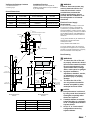
Overall Dimensions
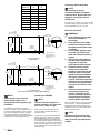
Raised Vent System Specifications
Raised Vent
Model No.
For Use With
For Use with Blower
Duct Size
ERV/PRV30
30” Ranges/Cooktops
REMP3/16
3 1/4”x10”, 8” & 10”
ERV/PRV36
36” Cooktops
REMP3/16
3 1/4”x10”, 8” & 10”
PRV46
46” Cooktops
REMP3/16
3 1/4”x10”, 8” & 10”
ERV48
48” Cooktops
REMP3/16
3 1/4”x10”, 8” & 10”
For detailed information on the remote blowers, refer to the Remote Blowers Installation Instructions.
3/4" (19mm) Max. backsplash thickness
1/4" (6mm) Min. flat area
Stud wall
Wall board
2 1/8"
(54mm)
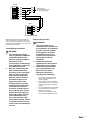
Failure to disconnect power may
result in electrical shock or fire
hazard! If the electric service
provided does not meet the
product specifications, do not
proceed with the installation. Call
the selling dealer or a licensed
electrician.
Electrical Power Supply
Requirements
It is the owner’s responsibility to ensure that
the electrical connection of this appliance
is performed by a qualified electrician. The
electrical installation, including minimum supply
wire size and grounding, must be in accordance
with the National Electric code ANSI/NFPA 702002* (or latest revision) and local codes and
ordinances.
*A copy of this standard may be obtained from:
National Fire Protection Association
1 Batterymarch Park
Quincy, Massachusetts 02269-9101
3"
(76mm)
1 15/16"
(49mm)
WARNING:
9/32" (7mm)
The correct 120VAC, 60Hz, 15A circuit must
be supplied for this appliance from a separate,
grounded, circuit that is protected by a properly
sized circuit breaker or time delay fuse.
Cooktop/Range
2 13/16"
(71mm)
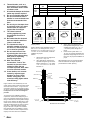
Duct Planning
3/8"
(10mm)
A
Warnings
1.
10"
(254mm)
Countertop
Stiffener
B
6 5/8”
(168mm)
1 7/8" x 16"
Exhaust duct
1 7/8" x 16"
Exhaust duct
18 13/16”
(478mm)
25 7/8"
30" (657mm)
(762mm)
3 3/4"
(95mm)
3 1/4" x 10"
Exhaust duct
6"
(152mm)
Motor
cover
3 1/4" x 10"
Rear
Exhaust duct
3/4" (19mm)
Electrical
access panel
3.
48", 3 prong
grounded
power cord
1 7/8" x 16"
Exhaust duct
Finished floor
2.
1 7/8" x 16"
Exhaust duct
8 1/2"
(216mm)
NOTES:
1.
ERV Overall Dimensions
Side View
ERV Overall Dimensions
Front View
Model
Width “A”
Width “B”
ERV/PRV30
30” (762mm)
27 3/4” (705mm)
ERV/PRV36
36” (914mm)
33 3/4” (857mm)
PRV46
46” (1168mm)
43 3/8” (1102mm)
ERV48
48” (1219mm)
43 3/8” (1102mm)
To reduce the risk of fire and
to properly exhaust air, ducted
fans must be vented to outside.
Do not vent exhaust air into
spaces within walls, ceilings,
attics, crawl spaces or garages.
Improper installation,
adjustment, alteration, service,
or maintenance can cause
personal injury or property
damage.
To reduce the risk of fire,
use only ductwork materials
deemed acceptable by state,
municipal and local codes.
2.
3.
Best performance is achieved
by using round duct instead of
rectangular, especially when
elbows are required.
If multiple elbows are needed,
ensure that there is a minimum
of 24” of straight duct between
any two elbows.
Avoid “S” or “back to back”
configurations caused by
adjacent elbows.