1
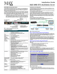
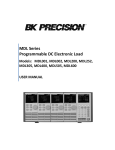
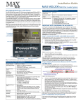
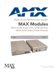
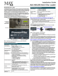
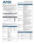
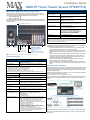
Installation Guide
MAX-HT Home Theater Servers (HT04/HT12)
MAX-HT04 & MAX-HT12 Home Theater Servers
The MAX-HT Home Theater Servers (FIG. 1) feature a robust internal hard drive
system that allows you to efficiently manage hundreds of DVDs and CDs. There are
two models of HT servers available, with different storage capacities:
• MAX-HT04 (FG 2178 - 14)
• MAX-HT12 (FG 2178 - 15)
MAX-HT Servers support multiple MAX-AVP Audio-Video Players and/or MAX-AVM
Audio/Video modules via Ethernet (up to 25 total), and up to 2 MAX-AOM Audio-Only
modules via USB.
MAX-HT04/HT12 Specifications (Cont.)
Dimensions (HWD):
(without rack ears)
• 8.75" x 16.95" x 18.90" (22.23 cm x 43.50 cm x 48.00 cm)
• 5 RU (mounts in a standard 19” equipment rack)
Weight (servers only):
• MAX-HT04: 60 lbs (27.22 kg)
• MAX-HT12: 68 lbs (30.84 kg)
Shipping Weight (including
mounting equipment and box)
• MAX-HT04: 83.9 lbs (38.06 kg)
• MAX-HT12: 91.9 lbs (41.69 kg)
Operating Environment:
• Operating Temperature: 10º to 35º C
• Operating Relative Humidity: 20% to 80% (non-condensing)
• Minimum Ventilation Clearance: 3" front and 3" rear
Included Accessories:
• One 6’ (1.83m) power cable
• One DVD, one CD
• Rack-Mounting Kit/Installation Guide
Other AMX/MAX Equipment:
•
•
•
•
•
Certifications:
UL Listed E252362, FCC, CE
Required Firmware version:
4.30.23 or greater - contact AMX Technical Support for details
Power ON/OFF toggle switch
MAX-AVP Audio-Video Player (FG 2178-51)
MAX-AVM Audio-Video Module (FG 2178-50)
MAX-AOM Audio-Only (USB) Module (FG 2178-55)
MAX-AOM-EX Expansion Kit (FG 2178-56)
MAX-MDL200 Multi-Disc Loader (FG 2179-01)
Notice: MAX Products are not designed or intended to, and may not be used to, violate anyone’s
copyright or other intellectual property rights. Each user of the MAX Products may only use the
Products in connection with materials legally owned or licensed by such user and only to the extent
such ownership or license rights permit such use.
Related Documents
Master
Power
switch
Power
cable
connector
USB 1 port
RS-232
VGA
USB 2 port
PS/2 keyboard
& mouse ports
ETHERNET CONTROL
switched Control segment
(to NetLinx Master or PC)
A/V OUT
switched GB Content segment
(to MAX-AVPs and/or MAX-AVMs)
FIG. 1 MAX-HT04/HT12 Home Theater Servers (Rear Panel Components)
Product Specifications
MAX-HT04/HT12 Specifications
Device Models:
• MAX-HT04 (FG 2178-14)
• MAX-HT12 (FG 2178-15)
Storage Capacity:
• MAX-HT04: 1.1 TBs, 275 DVDs (max) / 138 DVDs (min.)
• MAX-HT12: 4.0 TBs, 1000 DVDs (max) / 500 DVDs (min.)
Notes:
• The MAX number of DVDs is based on DVDs at 4.0 GB.
• The MIN number is based on the largest DVD at 8.0 GB.
• DVD capacity is based on typical commercial DVDs.
• DVD size is based on total DVD image, not the length of the movie.
The actual server capacity will vary depending on specific mix of DVDs and CDs in the library,
The following AMX documents provide additional information on the HT Servers and
related devices, and are available online at www.amx.com:
• Refer to the WinMAX Software manual for details on using WinMAX to add/
remove DVD/CD content on the server, and control playback.
• Refer to the MDL-200 Multi-Disc Loader System manual for details on using the
MDL200 Multi-Disc Loader System to bulk-load large numbers of discs to the
server.
• Refer to the MAX Servers manual for additional device information and configuration instructions for MAX servers, including instructions on rack-mounting,
changing the region code setting on the server’s internal DVD drive and a full
description of the options in the MAX Admin Menu.
• Refer to the MAX-AOM, MAX-AVM and MAX-AVP Installation Guides and
Instruction Manuals for detailed product information.
• Refer to the Setting Up a 4-Zone MAX-HT System manual for a step-by-step
description of how to set up a 4-Zone HT system with 4 MAX-AVPs and 1 MAXAOM.
Initial Setup and Configuration
Disc Management
RAID 5 disc drive system
The following sections describe the basic process of setting up a MAX-HT server and
making the configurations required to get the server up and running with one or more
MAX-AVP Audio/Video Players, MAX-AVM Audio/Video Modules and/or MAX-AOM
Audio-Only (USB) modules.
Follow the directions outlined below, and refer to FIG. 1 for the location and orientation
of the connectors mentioned in these steps.
Power:
110-240 VAC +/- 10%, 50/60Hz
Network Segment Layout for MAX-HT Servers
AC Current Draw - MAX-HT04:
120 VAC:
• Bootup/Power Cycle Peak - 3.0A @ 120V = 360 watts
• Normal Usage Peak - 1.9A @ 120V = 228 watts
240 VAC:
• Bootup/Power Cycle Peak - 1.5A @ 240V = 360 watts
• Normal Usage Peak - 0.95A @ 240V = 228 watts
It is required that the control (ETHERNET CONTROL) segment of the network is kept
separated from the (switched) content delivery (A/V OUT) segment, as indicated
below.
AC Current Draw - MAX-HT12:
120 VAC:
• Bootup/Power Cycle Peak - 6.0A @ 120V = 720 watts
• Normal Usage Peak - 3.0A @ 120V = 360 watts
240 VAC:
• Bootup/Power Cycle Peak - 3.0A @ 240V = 720 watts
• Normal Usage Peak - 1.5A @ 240V = 360 watts
Front Panel Components:
(remove Faceplate to access)
•
•
•
•
•
MAX-HT04: 4 hot-swappable 400GB hard drives
MAX-HT12: 12 hot-swappable 400GB hard drives
DVD/CDRW drive
Drive Status LEDs
Ventilated front cover
Rear Panel Components:
• Power Cable connector: IEC connector for AC power cable
(included)
• Master Power Supply switch: Turns the power supply on/off
• Power On/Off toggle switch: Turns the MAX-HT on/off
• PS/2 Keyboard and Mouse ports (for diagnostics only)
• USB ports 1 & 2: Type A USB connectors connect to MAX-AOM
module(s) for audio distribution
• RS-232 port: (for diagnostics only)
• VGA port: (for diagnostics only)
• ETHERNET CONTROL port: RJ-45 Gigabit Ethernet port
provides 1000/100/10 Mb/s network connectivity between the
MAX-HT and the NetLinx Master or PC
• A/V OUT port: RJ-45 Gigabit Ethernet port provides
1000/100/10 Mb/s network connectivity between the MAX-HT
and MAX-AVP Audio-Video Players and/or MAX-AVM
module(s) for A/V distribution
FIG. 2 Network Segment Layout
Note: Static electricity can damage electronic circuitry. Before touching the MAX-HT,
discharge any accumulated static electricity from your body by touching a grounded
metal object.
Step 1: Connect a Mouse, Keyboard and VGA Monitor
1.
Connect a PS/2 mouse and keyboard, and a VGA monitor directly to the server to
access the on-board interface, called the MAX Admin Menu (FIG. 3). You’ll use the
options in the Admin Menu to configure communication settings and add/remove
MAX-AVP Audio-Video Players as well as MAX-AVM and MAX-AOM modules.
Note: Alternatively, you can access the MAX Admin Menu via Telnet, using the
Server Configuration feature in the WInMAX software. This requires that the server is
configured with an IP address and Subnet Mask settings which are appropriate for
your network configuration. Refer to “Step 6: Install and Configure WinMAX
Software” for details.
2.
Step 2: Connect the Power Cable and Apply Power
In the MAX Admin Menu, select Output Module Setup > Add Output Module
> AOM.
In the Enter Output Number field, specify the first of up to 4 outputs on the
server that you want to assign to this AOM (range = 1 - 33).
Each AOM requires up to 4 server outputs to accommodate the 4 audio output/
zones provided by each AOM. Since the MAX-HT12 supports two AOMs (one
on each USB port), you can assign up to 8 server outputs. Select OK.
In the Enter USB Port Number field, enter the number of the USB port (1 or 2)
on the server that this MAX-AOM will be physically connected to. Select OK.
In the Enter AOM Output Number field, specify which audio output/zone on the
MAX-AOM (1-4) you are adding to the specified server output. Select OK.
A message is displayed to notify you that the AOM module has been added to
the system. Select OK to return to the Output Module Setup menu.
Repeat these steps to assign each of the AOM’s four audio output/zones to a
USB port and Output number on the server.
Notes: Always assign 4 consecutive server outputs to each MAX-AOM, even if
you don’t plan to use all of the AOM’s outputs right away.
Assign the 4 server outputs (per AOM) starting either with output #1 (if there
are no AVPs/AVMs on this server), or immediately after the last output
assigned to an AVP or AVM.
To avoid potential confusion later, do not mix AOM outputs and AVP/AVM outputs on the server.
Select Restart MAX daemon.
3.
4.
5.
Note: It is recommended that you use a UPS with the MAX-HT server, modules, and
ethernet switch (if applicable).
1.
Connect the power supply, using the supplied power cord.
2.
Flip the Master Power switch to the On position.
3.
Push the Power On/Off toggle switch to apply power.
4.
Allow up to one minute for the server to boot-up.
Shutting Down the MAX-HT Server
Always shut down the server via the Shutdown command in the MAX Admin Menu
(see below). This allows the operating system to shut down completely before power
is removed, and prevents the time-consuming re-initialization process that results
from an improper shut down (and cannot be cancelled).
Step 3: Access the MAX Admin Menu
Once the boot-up process is complete, the MAX Admin Menu (FIG. 3) is displayed:
6.
Step 5: Connect the Modules To the HT Server
Once the AVP players and AVM/AOM modules have been added to the server via
the MAX Admin Menu, you can physically connect them to the server:
Connecting MAX-AVPs and/or MAX-AVMs
Note: Multiple AVMs/AVPs require a GB Ethernet switch (not included).
1.
Connect the audio outputs, using either one of two options:
a. Use a mini-stereo to RCA adapter for analog audio output
b. Use a coaxial cable for digital audio output
2.
Use a S-Video cable to connect the video output on the AVM or AVP to a display device (MAX-AVMs also support VGA connections).
3.
Use ethernet cables to connect the ethernet port on the AVM or AVP to a GB
ethernet switch (not included), and the GB ethernet switch to the A/V OUT connector on the server.
4.
Connect the included power supply.
5.
Push the power button on the front panel of the AVM, and allow up to one
minute for the module to boot up. On the AVPs, the power switch is on the rear
panel.
Note: Power up the MAX-HT before applying power to the AVP(s) and/or AVM(s).
Connecting MAX-AOM Modules
FIG. 3 MAX Admin Menu
Working With the MAX Admin Menu
•
•
•
•
Use the arrow keys on the keyboard to highlight the desired option, and press
Enter to make a selection. Do not use the arrow keys on your keyboard’s
numeric keypad.
Beyond this menu, press the TAB button to navigate through the elements on
the pages until an asterisk appears next to the desired selection.
Press the spacebar to make a selection (press again to de-select).
For detailed descriptions of all options in the MAX Admin Menu, refer to the
MAX Servers Instruction Manual.
Step 4: Add MAX-AVPs, AVMs and AOMs to the HT Server
Before you can use MAX-AVP Audio-Video Players MAX-AVM or MAX-AOM
modules, they must each first be added to the server, via the Output Module Setup
options in the MAX Admin Menu. You should add the modules/players to the server
before making any physical connections.
Adding MAX-AVP Players and/or MAX-AVM Modules
Complete these steps for each MAX-AVM Audio-Video module and/or MAX-AVP
Audio-Video Player that you want to add to the MAX-HT:
Note: HT Servers treat MAX-AVPs exactly the same as MAX-AVMs, and the process
of adding them is identical.
1.
In the MAX Admin Menu, select: Output Module Setup > Add Output
Module > AVM.
2.
In the Enter Output Number field, specify the output on the server that you
want to assign to this AVP or AVM (range = 1 - 33). Each AVP/AVM requires
one output. Select OK to proceed.
Note: The server will not allow you to assign a module to an output/zone that is
already in use. Select Output Module Setup > View to review the current
output/zone assignments.
3.
In the Enter Serial Number field, enter the Setup Serial (Key) Number. This
number is printed on a decal located on the bottom of each AVM/AVP enclosure. The system will notify you that the AVP (or AVM) has been added to the
system.
Note: AVMs use a Setup “Serial” Number; AVPs use a Setup “Key” Number.
4.
Select OK to return to the Output Module Setup menu, select OK again to
return to the main menu.
5.
Select Restart MAX daemon.
Adding MAX-AOM Audio-Only Modules
Complete these steps for each MAX-AOM module that you want to add to the HT:
Note: When connecting USB cables to the HT server, always plug into the USB 1
port first. The USB 1 port is located on the right side of the rear panel (see FIG. 1).
Note: Do not use a USB hub with MAX-HT servers or AOM modules.
1.
Connect the MAX-AOM(s) to an audio system (amplifier, switcher, etc.), using
one of two options:
a. Use RCA cables for analog stereo output (L and R)
b. Use a coaxial cable for digital audio output (D)
2.
Connect the included power supply to apply power to the AOM.
3.
Use the supplied USB cable to connect the AOM module to a USB port on the
server.
Note: Power up the AOM(s) before connecting them to the server.
Step 6: Install and Configure WinMAX Software
Once the AVP players and AVM/AOM modules have been added and connected to
the server, you can use the WinMAX software application to initiate and control
playback of movies or music. If you intend to connect to the MAX-HT via a LAN
connection, verify that the PC is communicating properly with the network, and that
the server is powered and booted up.
1.
Use an ethernet cable to connect the ETHERNET CONTROL port on the
server to the LAN that the PC running WinMAX is on.
2.
Launch the WinMAX software on your PC and open the System Information
tab, where you can specify the network address of the server.
3.
Change the Server’s IP Address or URL field to match that of the server you
are connecting to. Click on the disk icon next to the text-entry field to save this
configuration.
If you are connecting to the server via a direct connection with a PC (using a
crossover ethernet cable), verify that the IP Address of the Network card in
your PC is in the same range as the server, but not the same as the server. For
example a network card setting of 192.168.1.31 will work with a server IP
address of 192.168.1.30.
4.
The blank fields should fill in momentarily, indicating that the MAX-HT has been
recognized.
If You Don’t Connect
•
•
Check ethernet cables and verify that all connections are intact.
If you are connecting to the server via a PC network, be sure that the
IP address and Subnet Mask settings are appropriate for your network
configuration. Consult your network administrator for help with this.
You can use WinMAX to establish a Telnet connection with the MAX-HT to access
the MAX Admin Menu: in the WinMAX System Information tab, click on Server
Configuration. You will be prompted for a User Name and Password. These are
case sensitive, and by default:
•
•
User Name = root
Password = mozart
For full warranty information, refer to the AMX Instruction Manual(s) associated with your Product(s).
065-004-2808 6/06
©2006 AMX. All rights reserved. AMX and the AMX logo are registered trademarks of AMX.
AMX reserves the right to alter specifications without notice at any time.
3000 RESEARCH DRIVE, RICHARDSON, TX 75082 • 800.222.0193 • fax 469.624.7153 • technical support 800.932.6993 • www.amx.com
93-2178-14
REV: C