1
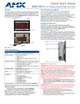
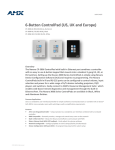
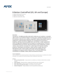
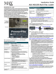
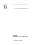
Installation Guide
MAX-AVP Audio/Video Player
Overview
MAX-AVP Specifications (Cont.)
The MAX-AVP Audio/Video Player (FG2178-51) provides standard media playback
and control functionality, featuring multiple audio and video outputs. The MAX-AVP
functions as a standalone player, and as a player for MAX server content (FIG. 1).
Key features include:
• Plays DVDs (and audio CDs) from its internal DVD/CD player
• Plays audio and video content over a CAT5 network interface from a MAX-HT
server.
• Provides A/V output in multiple formats: Component Video, Composite Video,
SVideo and HDMI™ (High-Definition Multimedia Interface).
• Provides both analog stereo and coaxial digital audio outputs. The supported
digital audio outputs are Dolby® Digital (S/PDIF), Dolby® Digital-Plus
(Surround 5.1, 7.1), and DTS® Surround.
• A Reset button is incorporated into the name plate on the front of the unit.
Audio Outputs:
• Digital:
- Dolby® Digital (S/PDIF)
- Dolby® Digital-Plus (Surround 5.1, 7.1)
- DTS® Digital Surround
• Analog: stereo
Front Panel Components:
•
•
•
•
Rear Panel Connectors:
• 1/4” DC power connector
• Power Switch
• Ethernet port: RJ-45 Ethernet port provides 10/100
network connectivity between the AVP and the MAX
server
• HDMI™ output: 19-pin HDMI cable connector
• Component Video output: 3 RCA connectors (Green,
Blue, Red)
• S-Video output: Mini-Din4 port
• Composite Video output: RCA connector (Yellow)
• Analog Audio outputs (R/L): RCA connectors
(Left = White, Right = Red)
• Coaxial (digital) Audio output: RCA connector (Orange)
Operating Environment:
• Operating temperature: 0º to 50º C (32° to 122° F)
• Storage temperature: -45º to +85º C (-49° to 185° F)
• Operating relative humidity: 5% to 85%
(non-condensing)
• Intended for indoor use only
Dimensions (HWD)
(without rack ears):
• 2" x 17" x 12.44"
(50.67 mm x 431.80 mm x 316.10 mm)
• 1 RU (mounts in a standard 19” equipment rack)
IR Receiver and Power/Standby LED
Disc Eject button
Reset button
Disc slot
(front)
Power Connector
Digital Audio (see Specifications table for details)
Power switch
Analog Stereo
Ethernet (to MAX Server)
(rear)
HDMI
Component Video
S-Video
Composite Video
Setup Key Number is printed on a decal on
the bottom panel of the AVP
Weight:
10.10 lbs (4.58 kg)
Included Accessories:
• AMX PS4.4 Power Supply (FG423-44)
• Handheld IR Remote Controller (FG2178-53)
• Audio/Video Cables (one of each):
- HDMI™ cable (6.5’ / 2.0m - FG10-2178-05)
- Component Video cable (6’ / 1.82m - FG10-2178-05)
- S-Video cable (6’ / 1.82m - FG10-2178-01)
- Composite Video cable (6’ / 1.82m - FG10-2178-04)
• Rackmount brackets (set of 2 - FG62-2178-46)
Other AMX Equipment:
• NXA-ENET24 Managed Ethernet Switch
(FG2178-60)
Certifications:
• FCC/CE Class B
• EN60950
Trademark
Acknowledgements:
• HDMI, and “High-Definition Multimedia Interface” are
trademarks or registered trademarks of HDMI Licensing
LLC.
• “Dolby” and the double-D symbol are trademarks of
Dolby Laboratories.
• “Dolby Digital” and “Dolby Digital-Plus” are registered
trademarks of Dolby Laboratories.
• “DTS” is a registered trademark of DTS, Inc.
Minimum Firmware
version:
1.00.15 or greater
MAX-AVP IR Remote Controller
FIG. 1 MAX-AVP
Note: Refer to the MAX-AVP Audio/Video Player Instruction Manual (available online
at www.amx.com) for additional information, including detailed descriptions of the IR
Remote Controller, and the MAX-AVP User Interface.
Product Specifications
MAX-AVP (FG2178-51) Specifications
Power:
• 13.5 VDC 4.4A external power supply (included)
• 110-240 VAC 50/60 Hz
Current Draw:
Peak
Running
DC:
• Current:
• Watt:
0.94
12.502
0.74
9.82
AC:
• Current:
• Watt:
0.125
14.925
0.101
12.0594
Supported media types:
Supported formats:
• DVD
• DVD+R/-R/-RW/+RW
• Audio CD
•
•
•
•
•
•
•
MPEG-2 MP/ML
AC3 audio
MP3 audio
LPCM audio
PCM audio
MPEG2 Layer 2 audio
FLAC audio
Video outputs:
•
•
•
•
Composite video
RGB Component video
S-Video
HDMI™ (High-Definition Multimedia Interface)
Video broadcast standards
• NTSC
• PAL
Supported Aspect Ratios:
• 4:3 - Pan & Scan (full screen)
• 4:3 - Letterbox
• 16:9 - Widescreen
IR Receiver and Power/Standby LED
CD/DVD-ROM drive slot
Disc Eject button
Reset button (doubles as the name plate)
MAX-AVP Supported Resolutions
Mode Name
Resolution
Outputs
NTSC (M)
525 line (480vis), 60 Hz, Interlaced, standard NTSC
• Composite
• Component
• HDMI
NTSC (M)
Japan
525 line (480 vis), 60 Hz, Interlaced, NTSC with
Japanese black-level
• Composite
• Component
• HDMI
PAL (BG)
625 line (576 vis), 50 Hz, Interlaced, standard PAL
• Composite
• Component
• HDMI
PAL M
525 line (480 vis), 60 Hz, Interlaced, NTSC framing
with PAL color
• Composite
• Component
• HDMI
•
•
MAX-AVP Supported Resolutions (Cont.)
Mode Name
Resolution
Outputs
PAL 60
525 line (480 vis), 60 Hz, Interlaced, NTSC framing
with PAL color
• Composite
• Component
• HDMI
480i60
525 line (480vis), 60 Hz, Interlaced, standard NTSC
• Composite
• Component
• HDMI
480p59
525 line (480 vis), 59.96Hz, NTSC Progressive Scan
• Component
• HDMI
576p50
625 line (576 vis), 50 Hz, PAL Progressive Scan
• Component
• HDMI
HDMI-only
modes
ATSC/DTSC standards for NTSC-style systems (59/60 hz)
and PAL-style systems (50hz)
• 720p59
• 720p60
• 720p50
• 1080i50
• 1080i59
• 1080i60
• 1080p50
• 1080p59
• 1080p60
Installation Procedures
There are two approaches to installing the MAX-AVP: either as a standalone DVD
player, or as a networked component of a MAX system. Both methods are described
below:
As a Stand Alone DVD Player
The MAX-AVP can be installed and used as a stand-alone DVD player, in which case
it behaves like any other consumer-level A/V component and offers several A/V
output options:
1.
Connect one of the two audio outputs on the AVP (Analog R/L or Coaxial) to an
audio amplifier.
2.
Connect one of the four video outputs (HDMI™, Component, S-Video or
Composite) on the AVP to a display device.
•
5.
Step Two: Connecting the AVP to a MAX-HT Server and Display Device
Note: Be sure to power up the server before applying power to the MAX-AVP.
1.
Use audio cables (not included) to connect to the audio output on the AVP to
an audio amplifier.
2.
Use one of the four video cables (HDMI, Component Video, S-Video or
Composite to connect to the video output on the AVP to the display device.
3.
Use an Ethernet cable to connect the AVP’s Ethernet port to a Gigabit Ethernet
switch.
4.
Use an Ethernet cable to connect the Gigabit switch to the A/V OUT connector
on the MAX-HT server.
5.
Connect the AVP’s included power supply.
6.
Turn on the power switch (on rear panel), and allow up to one minute for the
AVP to initialize.
Region Code Settings
Note that for DVDs, the region code of the DVD disc must match the region code
setting on the internal DVD drive on the AVP.
By default, AVP units are set to Region Code 1.
Use the Region Control options on the Setup Page - Locale tab (FIG. 3) to change
the DVD region code setting on the MAX-AVP:
Current DVD Region Code setting (Default = 1. N America)
As a Networked Component of a MAX System
•
•
4.
If other output modules (AOM, AVM or AVP) have already been added to the
server, then assign the AVP to the next available output.
Note that AVPs take only one output on the MAX-HT server.
In the Enter Serial Number field, enter the Key number of the AVP you are
adding to the system in the text box. The Key number is printed on a decal
located on the bottom panel of the AVP. The Key number is also indicated on
the AVP’s Setup page (press SETUP on the remote controller to access the
MAX-AVP Setup Page, and select the System tab).
The system will notify you that the module has been added to the system. Click
OK to return to the Output Module Setup menu.
Once the module has been added, select View from the Output Module Setup
menu. The module you just added should appear in the list of Installed Output
Modules. AVP modules are listed by MMS output /zone number assignment,
Key and IP address.
MMS servers communicate via Ethernet to up to 25 MAX-AVM Audio-Video
Modules and/or MAX-AVP Audio -Video Players.
Multiple AVMs and/or AVPs require a Gigabit Ethernet switch (not included) as
indicated in FIG. 2.
MAX-AVP
MAX-AVP
10/100
MAX-AVP
10/100
MAX-AVP
10/100
ETHERNET CONTROL (GB)
Number of region code
changes still allowed
FIG. 3 Setup Page - Locale tab (Region Control setting)
1.
10/100
Gigabit Ethernet
Switch
Press SETUP on the remote controller to access the MAX-AVP Setup Page,
and select the Locale tab.
Highlight DVD Region and press SELECT (on the remote controller) to scroll
through the different region codes (displayed in the text field) until you see the
region that you want to set the AVP to.
Highlight and select Set Region. The system prompts you to verify this action,
and reminds you of the number of region code changes still allowed.
Highlight and select Accept to change the region code, or Cancel to return to
the Setup Page – Locale tab without changing the region code.
2.
10/100
MAX-HT Server
(rear panel
connectors)
A/V OUT (GB)
10/100
10/100
3.
10/100
MAX-AVM
Note: The Region Code Setting can
only be changed a total of 4 times
from the factory default setting.
4.
Troubleshooting
MAX-AVM
MAX-AVM
MAX-AVM
FIG. 2 Example installation using multiple MAX-AVPs and AVMs
Adding the AVP to a MAX System
There are two procedures involved in adding the AVP to a MAX system:
IMPORTANT! MAX-HT Servers require a 24-hour initialization period. This simply
entails powering up the server and letting it charge and initiate for 24 hours before
use. Failure to allow this initialization to complete may cause performance problems
during media playback.
Step One: Installing the MAX-AVP Key In the MAX-HT Server
If the unit requires resetting, try the following:
•
•
A Reset button is incorporated into the name plate on the front of the unit.
If the unit loses network connectivity, or the unit needs to be reset for any
reason (such as after a firmware upgrade), lightly press and release the Reset
button.
Notice: MAX Products are not designed or intended to, and may not be used to,
violate anyone’s copyright or other intellectual property rights. Each user of the MAX
Products may only use the Products in connection with materials legally owned or
licensed by such user and only to the extent such ownership or license rights permit
such use.
In order for the AVP(s) in the system to be recognized by the MAX-HT server, they
must each be added to the system. Use the Server Configuration options in the
WinMAX software application (available for download at www.amx.com) to add AVPs
to the server.
Note: The process for adding AVPs to the MAX-HT server is identical to adding
AVMs: AVPs are added as AVMs in the Add Output Modules admin menu:
1.
Open the System Information tab in WinMAX, and click on the Server
Configuration button to access the MAX Admin menu.
2.
Go to Output Module Setup > Add Output Module > AVM to access the
Enter Output Number dialog.
3.
In the Enter Output Number field, enter an available server output/zone
number (range = 1 - 33). Click OK to proceed.
Note: The server will not allow you to assign an output to an output/zone that is
already in use. To determine which server outputs are already being used,
select View from the Output Module Setup menu.
For full warranty information, refer to the AMX Instruction Manual(s) associated with your Product(s).
10/08
©2008 AMX. All rights reserved. AMX and the AMX logo are registered trademarks of AMX.
AMX reserves the right to alter specifications without notice at any time.
3000 RESEARCH DRIVE, RICHARDSON, TX 75082 • 800.222.0193 • fax 469.624.7153 • technical support 800.932.6993 • www.amx.com
93-2178-51
REV: F