1
26
en | MIC Non-IR Power Supply Units
6.
MIC Series Power Supplies
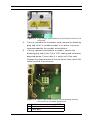
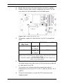
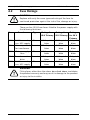
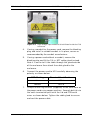
Carefully connect the Live and Neutral cores to the correct
HD1 screw terminals as shown below and also printed on
the PCB (next to the connector and not visible in the image
above).
7.
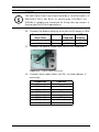
PCB Marking
Terminal Identification
Live
HD1-L
Neutral
HD1-N
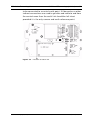
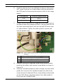
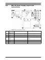
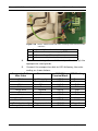
Crimp a 6 mm ring terminal (supplied) to the earth core on
the power cord using copper washers. Securely bolt this to
the earth termination post with the lid and PCB earth wires
as shown below. Tighten the cable gland to secure and
seal the power cord.
Figure 3.5
1
2
3
4
8.
Mains cable wired into HD1 showing earth terminal connections
Enclosure lid earth cable
Earth core from power supply PCB
Earth core from Mains cord
Enclosure earth termination post
Reattach the mains head-end shield taking care to avoid
pinching the cables and securely screw down as shown in
Figure 3.3.
9.
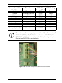
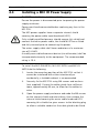
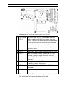
Feed the shielded composite cable through the metal M16
gland; then connect the shielded composite cable to the
screw terminal head-end HD3 as shown below and printed
on the PCB. When completed tighten the cable gland to
firmly grip the shielded cable.
F.01U.141.598 | 1.0 | 2009.11
Installation Manual
Bosch Security Systems, Inc.