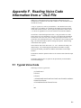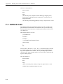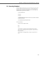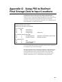
1
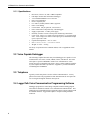
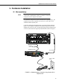
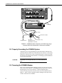
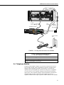
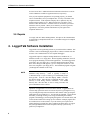
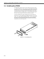
INSTRUCTION MANUAL COM300 Voice Communication Modem Revision: 10/02 C o p y r i g h t ( c ) 1 9 9 4 - 2 0 0 2 C a m p b e l l S c i e n t i f i c , I n c . Warranty and Assistance The COM300 VOICE COMMUNICATION MODEM is warranted by CAMPBELL SCIENTIFIC, INC. to be free from defects in materials and workmanship under normal use and service for twelve (12) months from date of shipment unless specified otherwise. Batteries have no warranty. CAMPBELL SCIENTIFIC, INC.'s obligation under this warranty is limited to repairing or replacing (at CAMPBELL SCIENTIFIC, INC.'s option) defective products. The customer shall assume all costs of removing, reinstalling, and shipping defective products to CAMPBELL SCIENTIFIC, INC. CAMPBELL SCIENTIFIC, INC. will return such products by surface carrier prepaid. This warranty shall not apply to any CAMPBELL SCIENTIFIC, INC. products which have been subjected to modification, misuse, neglect, accidents of nature, or shipping damage. This warranty is in lieu of all other warranties, expressed or implied, including warranties of merchantability or fitness for a particular purpose. CAMPBELL SCIENTIFIC, INC. is not liable for special, indirect, incidental, or consequential damages. Products may not be returned without prior authorization. The following contact information is for US and International customers residing in countries served by Campbell Scientific, Inc. directly. Affiliate companies handle repairs for customers within their territories. Please visit www.campbellsci.com to determine which Campbell Scientific company serves your country. To obtain a Returned Materials Authorization (RMA), contact CAMPBELL SCIENTIFIC, INC., phone (435) 753-2342. After an applications engineer determines the nature of the problem, an RMA number will be issued. Please write this number clearly on the outside of the shipping container. CAMPBELL SCIENTIFIC's shipping address is: CAMPBELL SCIENTIFIC, INC. RMA#_____ 815 West 1800 North Logan, Utah 84321-1784 CAMPBELL SCIENTIFIC, INC. does not accept collect calls. COM300 Voice Communication Modem Table of Contents PDF viewers note: These page numbers refer to the printed version of this document. Use the Adobe Acrobat® bookmarks tab for links to specific sections. 1. Introduction.................................................................1 2. Hardware and Software Requirements .....................1 2.1 2.2 2.3 2.4 COM300 Modem......................................................................................1 Voice Capable Datalogger ........................................................................2 Telephone .................................................................................................2 LoggerTalk Voice Communication Programming Software.....................2 3. Hardware Installation..................................................3 3.1 3.2 3.3 3.4 3.5 Site Installation .........................................................................................3 Properly Grounding the COM300 System ................................................4 Powering the COM300 Modem................................................................4 Telephone Service.....................................................................................5 Repairs ......................................................................................................6 4. LoggerTalk Software Installation...............................6 5. Using the COM300 for Standard Modem Communications in PC208W.....................................7 6. Additional Features ....................................................7 6.1 6.2 6.3 6.4 Security .....................................................................................................7 Commercial Mode ....................................................................................7 Renaming Menu Strings for Input Location, Ports, and Flags ..................7 Using the COM300 to Hear Output Location Data...................................8 7. Callback - Datalogger Initiated Calls .........................8 8. Troubleshooting..........................................................8 8.1 For Problems Encountered When Making Voice Calls ............................8 8.2 For Problems Encountered When Making Data Calls ..............................9 i COM300 Voice Communication Modem Table of Contents A. CS I/O 9 Pin Serial Port .......................................... A-1 A.1 Pin Description.................................................................................... A-1 B. Theory of Operation ............................................... B-1 B.1 Theory of Operation ............................................................................ B-1 C. Changing RAM or PROM Chips in the CR10 ........ C-1 C.1 Disassembling the CR10...................................................................... C-1 C.2 Installing New RAM Chips in CR10s with 16K RAM........................ C-1 C.3 Installing New PROM ......................................................................... C-2 D. FCC Warning to Users of Class A Computing Devices ................................................................... D-1 E. IC Information ......................................................... E-1 F. Reading Voice Code Information from a *.DLD File ................................................................ F-1 F.1 Typical Voice Code ..............................................................................F-1 F.2 Callback Code.......................................................................................F-2 F.3 Security Enabled ...................................................................................F-3 G. Using P80 to Redirect Final Storage Data to Input Locations ......................................................G-1 H. COM300 Word List ................................................. H-1 H.1 COM300 Word List - Numerical Order .............................................. H-1 H.2 COM300 Word List - Alphabetical Order........................................... H-4 List of Figures 1. COM300 Voice Synthesizer Modem ......................................................... 1 2. COM300 Hardware Connection Using Standard RJ11 Telephone Jack .... 3 3. COM300 Hardware Connection to CR10X Using Surge Protection Device...................................................................................... 4 4. Providing Alternate Power to the COM300 ............................................... 5 A-1 9 Pin Connector................................................................................... A-1 C-1 Disassembling CR10 ........................................................................... C-2 C-2 Jumper Settings for Different RAM Configurations............................ C-3 List of Tables 1. Dataloggers that Require Direct 12 VDC Connection to COM300 ........... 5 A-1 Pin Description.................................................................................... A-2 ii COM300 Voice Communication Modem 1. Introduction The COM300 voice-synthesizer modem allows Campbell Scientific's voice capable dataloggers to transmit, by voice announcement, data stored in input locations and the current status of datalogger control ports and user flags. With voice communication enabled, a user can call a datalogger site and listen to announcements, or the datalogger can be programmed to initiate voice calls when alarm conditions are met. Though voice communication is the primary function of the COM300 modem, the device is also capable of standard modem communications. This manual provides information specific to the COM300 hardware, including specifications, installation, and operation. Installation of the LoggerTalk Voice Communication Programming Software is covered, but use of the software is detailed in the software's on-line documentation. 2. Hardware and Software Requirements 2.1 COM300 Modem The COM300 modem (Figure 1) is required at the datalogger site to activate voice communication. The modem is shipped with an SC12 cable (9-pin to 9pin) to connect it to the datalogger's communication port. Surge protection at the datalogger site is required if it is not installed by the phone company. CSI offers a surge protector with or without environmental enclosure mounting hardware (model 6362 and 2372-01, respectively). The modem’s communication port is configured to be compatible with Campbell Scientific’s CS I/O port. This is not a standard RS232 connection. Refer to Appendix A for the configuration of this connector. CAMPBELL SCIENTIFIC INC. COM300 VOICE SYNTHESIZ Complies ER with Part 68, Ringer Eq FCC rules. uivalence FCC Regis 0.5A.Requ tration No. ired Conne B9QUSA-3 This equipm ctor USOC 140 2-MM-T ent complie computing RJ11C. s wit unaccepta device. Operationh the requirements whateve ble interference of this equipment in Part 15 of FCC r steps are Rules for to radio in a reside an Class A d TV rec ntial area necessary eption req S/N may cau to corre se uiring the ct the int operator erferenc to take e. G 12V IN USA GND MADE TIP 1002 RING NOTE FIGURE 1. COM300 Voice Synthesizer Modem 1 COM300 Voice Communication Modem 2.1.1 Specifications • • • • • • • • • • • • • • • Bell 212A, CCITT V.22, and V.32BIS compatible Full duplex at 9600 and 1200 baud to datalogger V.42 LAPM and MNP2-4 error correction Hayes AT command set RJ-11C telephone jack FCC and IC (formally known as DOC) approval Pulse or tone dialing Current drain: 100 µA quiescent, 180 mA active Direct connection to and powered by CSI dataloggers Supply requirements: 12 VDC power supply Internally switches 12 VDC external power minimizing current drain Logic levels: below 1.5 V inputs a low state and above 3.5 V inputs a high state. A low voltage level on the TX data input (pin 9) and RX data output (pin 4) represents a mark Operational temperature: -25°C to +50°C Size: 5.2” x 1.7” x 3.6” // 13.1 x 4.3 x 9.2 cm Weight: 0.75 lbs // 0.34 kg For theory of operation for the COM300 modem, refer to Appendix B of this manual. 2.2 Voice Capable Datalogger The following Campbell Scientific array based dataloggers are capable of voice communication: the CR10, CR10X, CR500, CR510, and CR23X. The CR10 will require a special UVEPROM to enable voice communication. If this special prom was not installed at the factory, please contact Campbell Scientific or your Campbell Scientific representative. Appendix C provides information on installing this UVEPROM. 2.3 Telephone Typically a touch-tone phone is used to call the COM300 modem. A rotary phone can be used if the programmed verbal announcements do not require the user to navigate through the modem's menu system. 2.4 LoggerTalk Voice Communication Programming Software Datalogger program files created using Campbell Scientific's Edlog program editor must be modified to include voice communication announcements. This modification is accomplished using LoggerTalk software, which is shipped with all COM300 modems. LoggerTalk requires a computer running Windows 95/NT/98. 2 COM300 Voice Communication Modem 3. Hardware Installation 3.1 Site Installation Connection to telephone company-provided COIN service (Central Office ImplemeNted systems) is prohibited. Connection to party line service is subject to state tariffs. The COM300 is designed to be used on standard device telephone lines. The COM300 connects to the telephone line by means of a USOC RJ11C jack (standard modular telephone jack). Connect the cable from the telephone RJ11C jack to the modem as shown in Figure 2. If the telephone company has not installed surge protection in the telephone line (no RJ11C jack), one must install surge protection (Model 6362 or 2372-01) and connect the ring and tip terminal blocks as shown in Figure 3. G 12V Logan, Utah SW 12V CTRL 7 SE DIFF 8 9 G H 10 11 12 6 L AG E3 AG G 5 4 G L AG H L AG H SW 12V G 5V 5V G G 12V POWER IN CS I/O G CR10X WIRING PANEL MADE IN USA SE DIFF 1 2 3 G H 4 5 2 1 G L AG H 6 SDM 3 L AG H L AG E1 AG E2 G P1 G P2 G C8 C7 C6 C5 C4 C3 C2 C1 G 12V 12V EARTH GROUND WIRING PANEL NO. To Earth Ground 14 AWG Ground Wire CAMPBELL SCIENTIFIC INC SC12 Cable COM300 VOICE . SYNTHESIZE Complies R with Ringer Equiv Part 68, FCC rules . FCC Regis alence 0.5A. tration No. Required B9QUSA-3 This equip Connector 1402-MMUSOC RJ11 computin ment complies with T C. g unaccept device. Operatio the requirements n of this able inter in Part 15 equipme whateve nt in a resid of FCC Rules for r steps areference to radio and TV Clas ential area necessar rece S/N may caus s A ption requ y to corr e ect the inter iring the operator ference. to take G 12V TIP MADE IN USA RING 1002 GND NOTE Telephone Wall Jack FIGURE 2. COM300 Hardware Connection Using Standard RJ11 Telephone Jack 3 COM300 Voice Communication Modem G 12V Logan, Utah G 12V POWER IN SW 12V CTRL SE DIFF 7 8 9 4 G G H 10 5 L AG H 11 12 6 L AG E3 AG G L AG H SW 12V G 5V 5V G CS I/O G CR10X WIRING PANEL MADE IN USA SE DIFF 1 2 3 G H 4 5 2 1 G L AG H 6 SDM 3 L AG H L AG E1 AG E2 G P1 G P2 G C8 C7 C6 C5 C4 C3 C2 C1 G 12V 12V EARTH GROUND WIRING PANEL NO. CAMPBELL SCIENTIFIC INC. COM300 VOICE SYNTHESIZER SC12 Cable S/N 0002 GND RING This equipment complies with the requirements in Part 15 of FCC Rules for Class A computing device. Operation of this equipment in a residential area may cause unacceptable interference to radio and TV reception requiring the operator to take whatever steps are necessary to correct the interference. TIP Complies with Part 68, FCC rules. FCC Registration No. B9QUSA-75378-MM-T Ringer Equivalence 0.5A. Required Connector USOC RJ11C. MADE IN USA Blue = Ring Burial Phone Cable To Earth Ground Blue/White = Tip Phone Line Transient Protector (Model 6362 or 2372-01) FIGURE 3. COM300 Hardware Connection to CR10X Using Surge Protection Device (No Standard RJ11 Connection Available) 3.2 Properly Grounding the COM300 System Connect the green 14 awg grounding wire (provided with the COM300) to the grounding terminal (GND) on the COM300 and to the enclosure’s earth ground connection. If the site does not have a grounded enclosure, connect the ground wire directly to an earth ground connection. The datalogger ground should also be tied to the earth ground. CAUTION The modem must be grounded for its transient protection to work. 3.3 Powering the COM300 Modem More recent Campbell Scientific dataloggers provide 12 VDC power on pin 8 of the CS I/O 9 pin connector. For dataloggers that do not provide 12 VDC on the datalogger's CS I/O 9 pin connector, 12 VDC and ground must be connected via the green power connector on the side of the COM300 (refer to Figure 4). Table 1 lists the Campbell Scientific dataloggers that require direct 12 VDC connection to the COM300. 4 COM300 Voice Communication Modem DIFF SE AG H L AG H L AG H L AG E3 AG G G 4 5 6 7 8 9 10 11 12 G G G G 12V 12V SWITCHED 12V SE DIFF SERIAL I/O G 12V POWER IN CAMPBELL SCIENTIFIC INC. CR10 MADE IN USA WIRING PANEL NO. SWITCHED 12V 1 2 3 4 5 6 CONTROL EARTH 1 2 3 G 5V 5V P1 P2 C8 C7 C6 C5 C4 C3 C2 C1 AG H L AG H L AG H L AG E1 E2 G G To Earth Ground Red (+12v) Black (Ground) 14 AWG Ground Wire SC12 Cable CAMPBELL SCIENTIFIC INC COM300 VOICE . SYNTHESIZE Complies R with Ringer Equiv Part 68, FCC rules . FCC Regis alence 0.5A tration No. .Required B9QUSA-3 This equip Connector 1402-MMUSOC RJ11 computin ment complies with T C. g unaccept device. Operatio the requirements n of this able inter in Part 15 equi whateve feren of pme FCC Rule ce to radio nt in a resid r steps are s for Clas and TV ential area necessar reception S/N may caus s A y to corr requiring e ect the inter the oper ference. ator to take G 12V TIP IN USA RING MADE GND 1002 Telephone Wall Jack FIGURE 4. Providing Alternate Power to the COM300 TABLE 1. Dataloggers that Require Direct 12 VDC Connection to COM300 CR10(X) w/ silver wiring panel CR10(X) w/ black CR10 wiring panel (P/N 8032) CR500serial number 1764 or lower 3.4 Telephone Service The goal of the telephone company is to provide you with the best service it can. In order to do this, it may occasionally be necessary for them to make changes in their equipment, operations, or procedures. If you have any questions about your telephone line, such as how many pieces of equipment you can connect to it, the telephone company will provide this information upon request. If the telephone company requests information concerning the equipment which you have connected to your telephone line, the FCC registration number and the ringer equivalence number (REN) of the COM300 5 COM300 Voice Communication Modem are listed on its label. Additional technical information from the FCC and IC on the COM300 is available in Appendix D and E, respectively. If any of your telephone equipment is not operating properly, you should remove it immediately from your telephone line, as it may cause harm to the telephone network. If the telephone company notes a problem, they may temporarily discontinue service. When practical, they will notify you in advance of this disconnection. If advance notice is not feasible, you will be notified as soon as possible. When you are notified, you will be given the opportunity to correct the problem and informed of your right to file a complaint with the FCC. 3.5 Repairs To comply with FCC Rules and Regulations, all repairs on the COM300 must be performed by Campbell Scientific, Inc. or an authorized agent of Campbell Scientific, Inc. 4. LoggerTalk Software Installation LoggerTalk Voice Programming software is provided with the COM300. This software is used to edit datalogger program files (*.DLD) to include code that activates voice communication in voice capable dataloggers. LoggerTalk requires a computer running Windows 95, Windows NT, or Windows 98 with a 3.5" floppy drive. Before beginning installation, close all active programs including virus and mail applications. To install LoggerTalk, insert disk 1 into your floppy drive. From the Windows Start Menu, choose Run. In the dialog box that appears, type in A:\Setup (this assumes A: is the drive letter assigned to your floppy drive). The installation program will guide you through the remainder of the setup. NOTE If an error occurs at the beginning of installation, check your Windows temp directory. (This is typically C:\Temp or C:\Windows\Temp. If you are unsure, go to an MS-DOS prompt and type SET. Look for a line that displays TEMP = and note the directory name.) Move all files to a different directory. This directory is used during software installation. The TEMP directory has a file limit that, if close to being exceeded, will prevent installation of the software. Operation of LoggerTalk is not covered in this manual. LoggerTalk has an extensive help system that can be accessed at any time by pressing the F1 key, or by selecting the Help menu item from the main window and by pressing the Help button on screens that have it. Two tutorials are included: a basic tutorial that walks you through creating voice strings, downloading the modified program to the datalogger, and navigating through the voice modem menus, and a more advanced tutorial for setting up voice callback. Example program files are included for use in the tutorials. If you do not have prior experience in editing datalogger program files with a Campbell Scientific editor, we suggest that you begin with the basic tutorial and peruse the help system for any questions you might have. 6 COM300 Voice Communication Modem Appendix F of this manual provides a guide to interpreting the code that is added to the end of the datalogger program file for voice communication. 5. Using the COM300 for Standard Modem Communications in PC208W The COM300 can be used for standard data transmission in PC208W. To establish data communication with the COM300, the dialing string (phone number) must be modified in PC208W to disable voice communication for the duration of that connection (the dialing string is found on the Hardware Tab of PC208W's Setup window). To disable voice communication, insert three commas and "9" at the end of the dialing string for your datalogger. For example, if the telephone number for your datalogger is "555-4321" you would need to make the following additions: "555-4321,,,9". Each of the three commas inserts a 2 second delay. The 9 disables voice communication. Depending upon the length of time required to establish connection with the modem, you may need to add more commas. For information on downloading a datalogger program to the COM300, refer to the Basic Tutorial in LoggerTalk's on-line help system. 6. Additional Features 6.1 Security A security code can be used with the COM300 to prevent users from accessing information beyond the initial messages. If security is not enabled, callers will have access to all input location data, and can change the status of datalogger ports and flags. Security is enabled by editing the datalogger program file in LoggerTalk. Refer to the LoggerTalk on-line help system for further information. If you forget the security code you can open the datalogger program in LoggerTalk and review what number you originally entered. NOTE This security code is different than the security code that can be entered to prevent access to certain datalogger functions. Refer to your datalogger operators manual for more information. 6.2 Commercial Mode When in Commercial Mode, the datalogger will announce the initial messages up to two times and then terminate the connection with the caller. A modem security code must always be entered in the LoggerTalk software when Commercial Mode is used. 6.3 Renaming Menu Strings for Input Location, Ports, and Flags When you call the datalogger, after the initial messages are announced you are prompted to hear the status of Input Locations, Ports, or Flags. These three 7 COM300 Voice Communication Modem terms can be renamed to something more descriptive using LoggerTalk. A dialog box to make these changes is invoked by selecting the Menu Strings button from the main LoggerTalk window. Refer to the LoggerTalk on-line help system for more information. 6.4 Using the COM300 to Hear Final Storage Data Output data is normally stored in the datalogger's ring memory (Final Storage). The COM300 can access data in input locations only; it cannot access Final Storage data. In order to hear Final Storage data, it must be redirected to an input location. This input location can then be accessed by the COM300. Datalogger Instruction 80 is used to redirect output data to input locations. Refer to the datalogger's operators manual for more information on this instruction, and to Appendix G for an example program using P80. 7. Callback - Datalogger Initiated Calls The datalogger can be programmed to initiate a call to one or more telephone numbers when a specific condition is met. Typical use of this feature is for the datalogger to call a computer running PC208W and transfer Final Storage data to the computer. However, this feature can also be used with voice communication. When callback is initiated, the datalogger will call the defined telephone number(s) and a message will be announced. This is particularly useful in alerting those monitoring the datalogger system of alarm conditions. LoggerTalk's on-line help system includes a tutorial to guide you through setting up a datalogger initiated voice callback. The datalogger's operators manual also includes general information on the callback feature. You can intermix voice and modem calls in the same program. Make sure you are not using the same flag for a voice and a modem call. 8. Troubleshooting 8.1 For Problems Encountered When Making Voice Calls 1) Can you attach a normal analog telephone to the line and make a call out? If not, contact your local telephone company. If you can make a call out but the connection is poor or faint, contact your local telephone company. 2) Verify the COM300 is receiving 12 VDC. If the COM300 is receiving 12 VDC from a separate power supply instead of the datalogger, is the ground of the separate power supply connected to the datalogger’s ground? 3) Verify the COM300 is the only Modem Enable device connected to the datalogger. Other common Campbell Scientific modem enable devices are the SC32A, some RF modems, and the MD9. 4) Verify the datalogger is turned on. 5) Verify the datalogger has power on its 5 V output. 8 COM300 Voice Communication Modem 8.2 For Problems Encountered When Making Data Calls 1) Verify you have selected the correct calling modem from PC208W's setup screen. 2) Verify the COM port you are using is activated. As a power saving feature, some notebook computers do not automatically activate the COM ports. 3) Verify nothing else is using the same COM port on the computer. Even if a program is minimized in Windows, it may have a lock on the COM port. 4) PC208W, Campbell Scientific's communication software, has a log level I/O log that will display an activity of communication as the link is being established. Assuming the above items are O.K., the software log should display something such as “ATDT#######”. Where the #### is the telephone number listed in the dialing path of the software for the datalogger you are trying to call. As you are connected to each device in the communications link, this will be reflected in the activity screen. This may help to pinpoint which device in the communications link is failing. To comply with FCC Rules and Regulations, all repairs on the COM300 modem must be performed by Campbell Scientific, Inc. or an authorized agent of Campbell Scientific, Inc. For assistance in installation, troubleshooting, or for repair, contact Campbell Scientific: Campbell Scientific, Inc., 815 West 1800 North Logan, Utah 84321-1784 Telephone: (435) 753-2342 Fax: (435) 750-9540 Web site: http://www.campbellsci.com/support.htm 9 COM300 Voice Communication Modem This is a blank page. 10 Appendix A. CS I/O 9 Pin Serial Port NOTE The modem’s CS I/O port is not a standard RS232 connection. A.1 Pin Description The COM300 modem connects to the datalogger using an SC12 cable connected to the devices’ 9-pin subminiature D-type socket connector. This connector is shown in Figure A-1. Table A-1 shows the I/O pin configuration, and gives a brief description of the function of each pin. CS I/O FIGURE A-1. 9 Pin Connector A-1 Appendix A. CS I/O 9 Pin Serial Port TABLE A-1. Pin Description ABR = Abbreviation for the function name. A-2 PIN = Pin number. O = Signal Out of the datalogger to a peripheral. I = Signal Into the datalogger from a peripheral. PIN ABR I/O Description 1 5V I 5 VDC supply. Not used. 2 SG 3 RING O Ring: Raised by the modem to put the datalogger in the telecommunications mode. 4 RXD O Receive Data: Serial data transmitted by the modem are transmitted on pin 4. 5 ME I Modem Enable: A logic high internally switches power to the modem. A logic low internally powers down the modem. 6 SDE I Synchronous Device Enable: A logic high disables communication with the modem, without removing power or changing the modem’s mode. 7 Clock/ HS I/O Clock/Handshake: Used with the SDE and TXD lines to communicate with devices that address it. 8 TE I +12 VDC power supply. 9 TXD I Transmit Data: Serial data are transmitted from the datalogger to the modem on pin 9; logic low marking (0V) logic high spacing (5V) standard asynchronous ASCII, 8 data bits, no parity, 1 start bit, 1 stop bit, 300, 1200, 9600, 76,800 baud (user selectable). Signal Ground: Provides a power return for pin 1 (5V), and is used as a reference for voltage levels. Appendix B. Theory of Operation B.1 Theory of Operation The COM300 modem is used to transmit data over bandwidth-limited channels such as telephone lines by modulating audio tones, using Phase Shift Keying (PSK) at 9600 or 1200 baud and Frequency Shift Keying (FSK) at 300 baud. The telephone company gives a 40 to 150 VRMS, 20 Hz signal on the telephone lines to signify a ring, which is typically on for 2 seconds and off for 4 seconds. The ring detection circuitry is continuously powered but draws less than 2 µA. The ring signal is passed on to the datalogger through an optocoupler. The datalogger responds by addressing the modem synchronously (pins 6 and 7) which switches on the 5 VDC power to the modem. The modem then answers and remains off-hook until it loses the carrier or the datalogger addresses a shut down command to the modem. The datalogger sends the shut down command either in response to an external command or after 40 seconds elapse without a command. The shut down command switches off the 5 VDC power to the modem, dropping power to the off-hook relay and thus placing the telephone line on-hook. To reject noise common to both telephone lines and to satisfy registration requirements, the modem circuitry is electrically isolated from the telephone lines by using an opto-isolator and coupling transformer. B-1 This is a blank page. Appendix C. Changing RAM or PROM Chips in the CR10 The CR10 has two sockets for Random Access Memory (RAM) and one socket for Programmable Read Only Memory (PROM). The standard CR10 has 64K of RAM, (a 32K RAM chip in each socket). Earlier CR10s had 16K of RAM (an 8K RAM chip in each socket). C.1 Disassembling the CR10 The sockets provided for RAM and PROM are located on the CR10 CPU circuit card inside the CR10 can. To expose the RAM and PROM sockets, remove the two Phillips head screws from the end opposite the connectors. Remove the end cap. The ends of two circuit cards and the RF shield will be visible (see Figure C-1). Now lay the CR10 on a flat surface, (i.e., a table), and push on the RF shield with your thumbs while grasping the can with your hands. Remove the circuit cards from the can. Orient the cards with the connector on the left and with the card that matches Figure C-2 component-side up. The Central Processing Unit (CPU) is found at location H-9 and the three slots for RAM and PROM will be directly beneath it. C.2 Installing New RAM Chips in CR10 with 16K RAM The two 8K RAM chips are found at locations C11 and C14. With a small flat screw driver gently pry out the two 8K RAM chips at these locations and replace them with the 32K RAM chips provided in the memory upgrade. The new chips should be installed so the notched end is towards the nearest card edge. Before pushing the chips into the socket make certain that all the pins are correctly seated. After installing the 32K chips, check for pins that may be bent or not firmly seated in the socket. If you notice a bent pin, remove the chip, carefully straighten it and repeat the installation procedure. C.2.1 Changing Jumpers There are six jumpers used to configure hardware for different RAM sizes. Figure C-2 shows the location of the jumpers and a magnified view of the jumper settings for different memory configurations. A pin or small screw driver tip will work best for pulling these jumpers and relocating them. C.2.2 RAM Test Attach the CR10KD Keyboard/Display and apply power to the CR10. After the CR10 executes the RAM/PROM self test, the number 96 should be displayed in the window. The number is the sum of Kbytes in RAM (64) plus the number of Kbytes in ROM (32). C-1 Appendix C. Changing RAM or PROM Chips in the CR10 C.3 Installing New PROM The PROM chip is found at location C8 on the CR10 CPU board, (see Figure C-2). With a small flat screw driver, gently pry out the PROM chip and replace it with the new one. The new chip should be installed so that the notched end is towards the nearest card edge. Before pushing the chip into the socket make certain that all the pins are seating correctly. After installing the chip, check for pins that may be bent or not making contact. If you notice a bent pin, remove the chip, carefully straighten it and repeat the installation procedure. To make certain that the new chip is installed correctly enter the CR10 *B mode (Section 1.6 in the CR10 Operator's Manual) and advance to the second window. This window displays the PROM signature. The five digit number in the window should match the PROM signature given with the new PROM documentation. If the numbers are different, disassemble the CR10 and look for pins that are bent or not firmly seated. FIGURE C-1. Disassembling CR10 C-2 Appendix C. Changing RAM or PROM Chips in the CR10 FIGURE C-2. Jumper Settings for Different RAM Configurations C-3 Appendix C. Changing RAM or PROM Chips in the CR10 This is a blank page. C-4 Appendix D. FCC Warning to Users of Class A Computing Devices WARNING This equipment generates, uses, and can radiate radio frequency energy, and if not installed and used in accordance with the instruction manual, may cause interference to radio communications. It has been tested and found to comply with the limits for a Class A computing device pursuant to Subpart J of Part 15 of FCC Rules, which are designed to provide reasonable protection against such interference when operated in a COMMERCIAL ENVIRONMENT. Operation of this equipment in a residential area may cause interference to radio and television reception. The operator must take whatever measures are necessary to correct the interference. The REN is used to determine the quantity of devices which may be connected to the telephone line. Excessive REN’s on the telephone line may result in the devices not ringing in response to an incoming call. In most, but not all areas, the sum of the REN’s should not exceed five (5.0). To be certain of the number of devices that may be connected to the line, as determined by the total REN’s, contact the telephone company to determine the maximum REN for the calling area. This equipment cannot be used on the telephone company-provided coin service. Connection to Party Line Service is subject to State Tariffs. If this equipment cannot be used on the telephone network, the telephone company will notify you in advance that temporary discontinuance of service may be required. If advance notice isn’t practical, the telephone company will notify the customer as soon as possible. Also, you will be advised of your right to file a complaint with the FCC if you believe it is necessary. D-1 This is a blank page. Appendix E. IC Information NOTE Industry Canada (IC) was formally known as DOC. CP-01, Issue 8, Part I Section 14.1 “NOTICE: The Industry Canada label identifies certified equipment. This certification means that the equipment meets certain telecommunications network protective, operational and safety requirements as prescribed in the appropriate Terminal Equipment Technical Requirements document(s). The Department does not guarantee the equipment will operate to the user’s satisfaction. “Before installing this equipment, users should ensure that it is permissible to be connected to the facilities of the local telecommunications company. The equipment must also be installed using an acceptable method of connection. The customer should be aware that compliance with the above conditions may not prevent degradation of service in some situations. “Repairs to certified equipment should be coordinated by a representative designated by the supplier. Any repairs or alterations made by the user to this equipment, or equipment malfunctions, may give the telecommunications company cause to request the user to disconnect the equipment. “Users should ensure for their own protection that the electrical ground connections of the power utility, telephone lines and internal metallic water pipe system, if present, are connected together. This precaution may be particularly important in rural areas. CAUTION Users should not attempt to make such connections themselves, but should contact the appropriate electric inspection authority, or electrician, as appropriate.” CP-01, Issue 8, Part I Section 14.2 “NOTICE: The Ringer Equivalence Number (REN) assigned to each terminal device provides an indication of the maximum number of terminals allowed to be connected to a telephone interface. The termination on an interface may consist of any combination of devices subject only to the requirement that the sum of the Ringer Equivalence Numbers of all the devices does not exceed 5.” E-1 This is a blank page. Appendix F. Reading Voice Code Information from a *.DLD File When a file is edited and saved in LoggerTalk, the information for voice communication is added to the end of the *.DLD file. This information can be verified for accuracy. A copy of typical voice code is provided below. The numbers between the "smiley faces" (☺) and the "&" symbols are the numbers associated with the words used from the word list. The ☺ symbol is equivalent to control code A (^A). Refer to Appendix H to review the word list used with the COM300. Several lines of code that begin with a tilde (~) may precede the voice code. These strings are set up information. The voice code follows this information. The first line of the voice code is the wording used for input locations. The second line is the wording used for ports. The third line is the wording used for flags. The lines following are used for message descriptions. Each message will terminate with a period. Notice that line four below starts with ">\4". The > indicates the string is an initial message. The 4 following the slash indicates the number of digits following the decimal point that the COM300 will announce for that input location. The numbers inside the quotation marks are the words associated with the input location. The number following the "$" symbol is the input memory location number used in the datalogger. F.1 Typical Voice Code Following is code for a typical call: ;|#"☺56&☺57&"# #"☺53&"# #"☺52&"# >\4☺88&☺89&☺109&☺74&☺71&☺71&☺71&"☺109&☺135&☺86&" ☺85&$3☺87&☺122&.\ \4"☺109&☺98&☺191&"☺85&$1☺192&.\ | ♣♣ F-1 Appendix F. Reading Voice Code Information from a “.DLD File The above code translates to: Input Locations Ports Flags (four decimal places) Campbell Scientific Datalogger Program (pause) (pause) (pause) "Datalogger Internal Temperature" is (input location 3) Degrees Fahrenheit. (four decimal places) Datalogger Battery Voltage is (input location 1) Volts. F.2 Callback Code If the datalogger has been programmed to initiate voice calls, you will see the phone number associated with the call command at the very end of the listing. The flag number used to initiate the call and the phone number will be between "at" symbols (@). This example initiates a voice call: ;|#"☺56&☺57&"# #"☺53&"# #"☺52&"# ><2\4"☺98&☺191&"☺85&$1☺192&.\ @2555-1234@ | ♣♣ Line four, above, starts out as “><2/4”. The “>” means this message is selected as an initial message. The “<2” indicates that this message will be spoken if flag 2 is the flag that initiates callback. The “2” preceding the phone number “@2555-1234@” means the phone number (555-1234) will be called when flag 2 goes low in the program. The code translates as: Input Locations Ports Flags (flag 2) (4 decimal places) "Battery Voltage" Is (input location 1) Volts. (callback flag 2) (telephone number 555-1234) F-2 Appendix F. Reading Voice Code Information from a *.DLD File F.3 Security Enabled This last example uses the security code "1234" to allow access to the second level menu. Notice the characters following the "?" at the beginning of the character stream. The security code will always be the very first thing in the imbedded character portion of the *.DLD file. ;|?1234#"☺56&☺57&"# #"☺53&"# #"☺52&"# >\4☺88&☺89&☺109&☺74&☺71&☺71&☺71&"☺109&☺135&☺86&" ☺85&$3☺87&☺122&.\ \4"☺109&☺98&☺191&"☺85&$1☺192&.\ This code translates to: (security code 1234) Input Locations Ports Flags (4 decimal places) Campbell Scientific Datalogger Program (pause) (pause) (pause) "Datalogger Internal Temperature" Is (input location 3) Degrees Fahrenheit. (4 decimal places) "Datalogger Battery Voltage" Is (input location 1) Volts. F-3 Appendix F. Reading Voice Code Information from a “.DLD File This is a blank page. F-4 Appendix G. Using P80 to Redirect Final Storage Data to Input Locations The following section of code provides an example of using datalogger Instruction 80 to redirect Final Storage data to input locations. This is not a complete program. Instructions would be included prior to this section of code to measure sensors, perform control functions, and provide initial data processing. All text entries preceded by a semicolon (;) are comments inserted by the programmer to explain the instructions. ;The following section of code uses ;program instruction 80 to redirect ;data from final storage to input locations 32: If time is (P92) 01: 0000 02: 60 03: 10 minutes into a minute interval Set high Flag 0 33: Set Active Storage Area (P80) 01: 3 Input Storage Area 02: 5 Array ID or location 34: Maximize (P73) 01: 1 02: 11 03: 4 ; output data ; parameter 3 directs data to input storage ; starting at location 5 Rep Value with Hr-Min-Sec Loc AIR TEMPC Every sixty minutes the maximum air temperature will be stored in location #5. No output data will be sent to Final Storage. Instruction 80 should follow the instruction setting Flag 0, and should precede the output instructions. Keep in mind that all output processing instructions following Instruction 80 will be redirected to input storage until another Instruction 80 is used or until the program table is executed again (output defaults to Final Storage Area 1 at the beginning of the program table). G-1 This is a blank page. Appendix H. COM300 Word List H.1 COM300 Word List - Numerical Order 1. 2. 3. 4. 5. 6. 7. 8. 9. 10. 11. 12. 13. 14. 15. 16. 17. 18. 19. 20. 21. 22. 23. 24. 25. 26. 27. 28. 29. 30. 31. 32. 33. 34. 35. 36. 37. 38. 39. 40. 41. 42. 43. 44. 45. 46. 47. 48. ZERO ONE TWO THREE FOUR FIVE SIX SEVEN EIGHT NINE TEN ELEVEN TWELVE THIRTEEN FOURTEEN FIFTEEN SIXTEEN SEVENTEEN EIGHTEEN NINETEEN TWENTY THIRTY FORTY FIFTY SIXTY SEVENTY EIGHTY NINETY HUNDRED THOUSAND MILLION PRESS POUND DEW HEAR MENU AGAIN STAR DISCONNECT YOU THE HAVE SELECTED MONITOR KEY FOLLOWING RETURN PREVIOUS 49. 50. 51. 52. 53. 54. 55. 56. 57. 58. 59. 60. 61. 62. 63. 64. 65. 66. 67. 68. 69. 70. 71. 72. 73. 74. 75. 76. 77. 78. 79. 80. 81. 82. 83. 84. 85. 86. 87. 88. 89. 90. 91. 92. 93. 94. 95. 96. STATUS HIGH LOW TOGGLE FLAGS PORTS THRU PORT INPUT LOCATIONS FLAG AND OF SECURITY CODE YOUR POINT PLEASE BY MINUS ENTER SELECTION GOODBYE 50MS MESSAGE CALLBACK PROGRAM SIGNATURE EPROM KILOBYTES MEMORY NUMBER E08'S TABLE OVERRUNS VERSION REVISION IS TEMPERATURE DEGREES CAMPBELL SCIENTIFIC ACRE AIR ALARM ARE AT AVERAGE 97. 98. 99. 100. 101. 102. 103. 104. 105. 106. 107. 108. 109. 110. 111. 112. 113. 114. 115. 116. 117. 118. 119. 120. 121. 122. 123. 124. 125. 126. 127. 128. 129. 130. 131. 132. 133. 134. 135. 136. 137. 138. 139. 140. 141. BAROMETRIC BARS BATTERY CALIBRATE CELSIUS CENTI CHILL CLOSED CONDUCTIVITY CUBIC CURRENT DAM DATA DATALOGGER DAY DEPTH DEVIATION DIRECTION D-O DOWN DRAW EQUAL E-T-O EVENT EXTERNAL EXCEEDS FAHRENHEIT FALL FEET FLOW FROM GALLONS GRAM HELLO SET HOUR HUMIDITY IN INCHES INTERNAL KILO LAST LEVEL LITER RESET H-1 Appendix H. COM300 Word List 142. 143. 144. 145. 146. 147. 148. 149. 150. 151. 152. 153. 154. 155. 156. 157. 158. 159. 160. 161. 162. 163. 164. 165. 166. 167. 168. 169. 170. 171. 172. 173. 174. 175. 176. 177. 178. 179. 180. 181. 182. 183. 184. 185. 186. 187. 188. 189. 190. 191. 192. 193. 194. 195. 196. H-2 MAXIMUM MERCURY METER METERS MICRO MILES MILLI MINIMUM MINUTE MOISTURE MONTH MULTIPLIER NEW N-T-U OFF OFFSET ON OPEN OVERFLOW PARTS PER PERCENT P-H PRECIPITATION PRESSURE PROGRESS P-S-I RADIATION RAIN RATE REFERENCE RELATIVE R-P-M SAMPLE SECOND SECONDS SIEMENS SITE SNOW SOIL SOLAR SPEED SQUARED STAGE STANDARD STATION STORM TIME TURBIDITY VELOCITY VOLTAGE VOLTS WARNING WATER WATTS 197. 198. 199. 200. 201. 202. 203. 204. 205. 206. 207. 208. 209. 210. 211. 212. 213. 214. 215. 216. 217. 218. 219. 220. 221. 222. 223. 224. 225. 226. 227. 228. 229. 230. 231. 232. 233. 234. 235. 236. 237. 238. 239. 240. 241. 242. 243. 244. 245. 246. 247. 248. 249. 250. 251. WEATHER WELL WIND A A-M ABOVE ACCUMULATE ACKNOWLEDGE ADDITION ADDITIONAL AGO ALL AMMONIUM APPROACH AREA AVAILABLE B BACK-UP BAY BE BEAVER BEDS BEHIND BELOW BIG BILLION BLAST BOILER BUILDING C C-O CALCIUM CALL CALLS CAN CEMENT CENTRAL CHECK CHILLER CHLORIDE CHLORINE CONTACT CORRECTED CROSSING CYCLES D DAYS DELTA DING DISTRICT DIVERSION DOCK DOOR DURING E 252. 253. 254. 255. 256. 257. 258. 259. 260. 261. 262. 263. 264. 265. 266. 267. 268. 269. 270. 271. 272. 273. 274. 275. 276. 277. 278. 279. 280. 281. 282. 283. 284. 285. 286. 287. 288. 289. 290. 291. 292. 293. 294. 295. 296. 297. 298. 299. 300. 301. 302. 303. EAST EASTERN EFFLUENT ELECTRON ELEVATION EMPTIED ENGINE ERROR F FAILED FAILURE FALLING FIRST FLUORIDE FREEZER FREQUENCY FRIDAY FUEL G GAS GATE GAUGE GENERATOR GOING GOOD GRADIENT GRASS GROUND H H-2-S HAD HARDNESS HAS HASH HEAD HEAT HERTZ HOLD HOT HOURS HYDROLOGIC I INDEX ING INTAKE INTRUDER IRRADIANT IRRIGATION IT J K KNOTS Appendix H. COM300 Word List 304. 305. 306. 307. 308. 309. 310. 311. 312. 313. 314. 315. 316. 317. 318. 319. 320. 321. 322. 323. 324. 325. 326. 327. 328. 329. 330. 331. 332. 333. 334. 335. 336. 337. 338. 339. 340. 341. 342. 343. 344. 345. 346. 347. 348. 349. 350. 351. 352. 353. 354. 355. 356. 357. 358. L LAKE LAYER LINE LOAD LOCATED LOCATION LOGAN M M-R-P MANAGEMENT MENDON MID MID-MOUNTAIN MIDNIGHT MINUTES MODEM MONDAY MOUNT MOUNTAIN N NEEDS NETWORK NEXT NITRATE NITROGEN NO NOON NORTH NOT O OK OR OUT OZONE P P-M PACIFIC PARAMETER PAST PEAK PENDING PHONE PLANT POND POTASSIUM POWDER POWER PREHEAT PROBE PRODUCT PUMP Q QUALITY QUIT 359. 360. 361. 362. 363. 364. 365. 366. 367. 368. 369. 370. 371. 372. 373. 374. 375. 376. 377. 378. 379. 380. 381. 382. 383. 384. 385. 386. 387. 388. 389. 390. 391. 392. 393. 394. 395. 396. 397. 398. 399. 400. 401. 402. 403. 404. 405. 406. 407. 408. 409. 410. 411. 412. 413. R RACE RADIAL RANGE REACHED READING RECEIVED RESERVOIR RESIDUAL RISING RIVER ROAD ROOM RUN RUNOFF S S-O-2 SATURDAY SEDIMENT SENSOR SENSORS SHAFT SINCE SKIING SMOG SODIUM SONAR SOUTH SPILL STATES STREAMBED SUMMIT SUMP SUNBURN SUNDAY SURFACE SURFACTANCE SYSTEM T TAIL TESTING THANK THAT THIS THRESHOLD THURSDAY TING TO TODAY TODAYS TOTAL TRIGGERED TUESDAY U ULTRAVIOLET 414. 415. 416. 417. 418. 419. 420. 421. 422. 423. 424. 425. 426. 427. 428. 429. 430. 431. 432. 433. UNITS UP V V-O-C VALUE VERTICAL VIA W WAS WE WEDNESDAY WELCOME WEST WHAT WITH X Y YEAR YESTERDAY Z H-3 Appendix H. COM300 Word List H.2 COM300 Word List - Alphabetical Order 71. 199. 200. 201. 202. 203. 90. 204. 205. 36. 206. 91. 92. 207. 208. 59. 209. 93. 210. 94. 211. 95. 212. 213. 96. 97. 98. 214. 215. 216. 217. 218. 219. 220. 221. 222. 223. 224. 66. 225. 226. 227. 99. 228. 73. 229. 88. 230. 100. 231. 101. 232. H-4 50MS A A-M ABOVE ACCUMULATE ACKNOWLEDGE ACRE ADDITION ADDITIONAL AGAIN AGO AIR ALARM ALL AMMONIUM AND APPROACH ARE AREA AT AVAILABLE AVERAGE B BACK-UP BAROMETRIC BARS BATTERY BAY BE BEAVER BEDS BEHIND BELOW BIG BILLION BLAST BOILER BUILDING BY C C-O CALCIUM CALIBRATE CALL CALLBACK CALLS CAMPBELL CAN CELSIUS CEMENT CENTI CENTRAL 233. 102. 234. 235. 236. 103. 62. 104. 237. 238. 239. 105. 106. 240. 241. 114. 107. 108. 109. 110. 242. 87. 243. 111. 112. 33. 244. 113. 38. 245. 246. 247. 248. 115. 116. 249. 250. 118. 80. 251. 252. 253. 8. 18. 26. 254. 255. 11. 256. 257. 68. 76. CHECK CHILL CHILLER CHLORIDE CHLORINE CLOSED CODE CONDUCTIVITY CONTACT CORRECTED CROSSING CUBIC CURRENT CYCLES D D-O DAM DATA DATALOGGER DAY DAYS DEGREES DELTA DEPTH DEVIATION DEW DING DIRECTION DISCONNECT DISTRICT DIVERSION DOCK DOOR DOWN DRAW DURING E E-T-O E08'S EAST EASTERN EFFLUENT EIGHT EIGHTEEN EIGHTY ELECTRON ELEVATION ELEVEN EMPTIED ENGINE ENTER EPROM 117. EQUAL 258. ERROR 119. EVENT 121. EXCEEDS 120. EXTERNAL 259. F 122. FAHRENHEIT 260. FAILED 261. FAILURE 123. FALL 262. FALLING 124. FEET 15. FIFTEEN 23. FIFTY 263. FIRST 5. FIVE 58. FLAG 52. FLAGS 125. FLOW 264. FLUORIDE 45. FOLLOWING 22. FORTY 4. FOUR 14. FOURTEEN 265. FREEZER 266. FREQUENCY 267. FRIDAY 126. FROM 268. FUEL 269. G 127. GALLONS 270. GAS 271. GATE 272. GAUGE 273. GENERATOR 274. GOING 275. GOOD 70. GOODBYE 276. GRADIENT 128. GRAM 277. GRASS 278. GROUND 279. H 280. H-2-S 281. HAD 282. HARDNESS 283. HAS 284. HASH 41. HAVE Appendix H. COM300 Word List 285. 34. 286. 129. 287. 49. 288. 289. 131. 290. 132. 28. 291. 292. 133. 134. 293. 294. 56. 295. 135. 296. 297. 298. 85. 299. 300. 301. 44. 136. 77. 302. 303. 304. 137. 305. 138. 306. 139. 307. 308. 309. 57. 310. 50. 311. 312. 313. 141. 78. 314. 35. 142. 72. 143. HEAD HEAR HEAT HELLO HERTZ HIGH HOLD HOT HOUR HOURS HUMIDITY HUNDRED HYDROLOGIC I IN INCHES INDEX ING INPUT INTAKE INTERNAL INTRUDER IRRADIANT IRRIGATION IS IT J K KEY KILO KILOBYTES KNOTS L LAKE LAST LAYER LEVEL LINE LITER LOAD LOCATED LOCATION LOCATIONS LOGAN LOW M M-R-P MANAGEMENT MAXIMUM MEMORY MENDON MENU MERCURY MESSAGE METER 144. 145. 315. 316. 317. 146. 147. 30. 148. 67. 149. 318. 319. 150. 320. 43. 151. 321. 322. 152. 323. 154. 324. 325. 153. 326. 9. 19. 27. 327. 328. 329. 330. 331. 332. 79. 333. 60. 155. 156. 334. 157. 1. 158. 335. 336. 159. 82. 337. 338. 163. 339. 167. 340. 341. METERS MICRO MID MID-MOUNTAIN MIDNIGHT MILES MILLI MILLION MINIMUM MINUS MINUTE MINUTES MODEM MOISTURE MONDAY MONITOR MONTH MOUNT MOUNTAIN MULTIPLIER N N-T-U NEEDS NETWORK NEW NEXT NINE NINETEEN NINETY NITRATE NITROGEN NO NOON NORTH NOT NUMBER O OF OFF OFFSET OK ON ONE OPEN OR OUT OVERFLOW OVERRUNS OZONE P P-H P-M P-S-I PACIFIC PARAMETER 160. 342. 343. 344. 161. 162. 345. 346. 65. 64. 347. 55. 53. 348. 32. 349. 350. 164. 351. 31. 165. 47. 352. 353. 74. 166. 354. 355. 356. 357. 358. 173. 359. 360. 168. 169. 361. 170. 362. 363. 364. 171. 172. 365. 140. 366. 46. 84. 367. 368. 369. 370. PARTS PAST PEAK PENDING PER PERCENT PHONE PLANT PLEASE POINT POND PORT PORTS POTASSIUM POUND POWDER POWER PRECIPITATION PREHEAT PRESS PRESSURE PREVIOUS PROBE PRODUCT PROGRAM PROGRESS PUMP Q QUALITY QUIT R R-P-M RACE RADIAL RADIATION RAIN RANGE RATE REACHED READING RECEIVED REFERENCE RELATIVE RESERVOIR RESET RESIDUAL RETURN REVISION RISING RIVER ROAD ROOM H-5 Appendix H. COM300 Word List 371. 372. 373. 374. 174. 375. 89. 175. 176. 61. 376. 42. 69. 377. 378. 130. 7. 17. 25. 379. 177. 75. 380. 178. 6. 16. 24. 381. 382. 179. 383. 180. 181. 384. 385. 182. 386. 183. 184. 185. 37. 387. 186. 48. 187. 388. 389. 390. 391. 392. 393. 394. 395. 396. 81. H-6 RUN RUNOFF S S-O-2 SAMPLE SATURDAY SCIENTIFIC SECOND SECONDS SECURITY SEDIMENT SELECTED SELECTION SENSOR SENSORS SET SEVEN SEVENTEEN SEVENTY SHAFT SIEMENS SIGNATURE SINCE SITE SIX SIXTEEN SIXTY SKIING SMOG SNOW SODIUM SOIL SOLAR SONAR SOUTH SPEED SPILL SQUARED STAGE STANDARD STAR STATES STATION STATUS STORM STREAMBED SUMMIT SUMP SUNBURN SUNDAY SURFACE SURFACTANCE SYSTEM T TABLE 397. 86. 10. 398. 399. 400. 40. 13. 21. 401. 29. 3. 402. 54. 403. 188. 404. 405. 406. 407. 51. 408. 409. 410. 189. 12. 20. 2. 411. 412. 413. 414. 415. 416. 417. 190. 83. 418. 419. 191. 192. 420. 193. 421. 194. 195. 422. 196. 423. 424. 197. 425. 426. 198. 427. TAIL TEMPERATURE TEN TESTING THANK THAT THE THIRTEEN THIRTY THIS THOUSAND THREE THRESHOLD THRU THURSDAY TIME TING TO TODAY TODAYS TOGGLE TOTAL TRIGGERED TUESDAY TURBIDITY TWELVE TWENTY TWO U ULTRAVIOLET UNITS UP V V-O-C VALUE VELOCITY VERSION VERTICAL VIA VOLTAGE VOLTS W WARNING WAS WATER WATTS WE WEATHER WEDNESDAY WELCOME WELL WEST WHAT WIND WITH 428. 429. 430. 431. 39. 63. 432. 0. X Y YEAR YESTERDAY YOU YOUR Z ZERO This is a blank page. Campbell Scientific Companies Campbell Scientific, Inc. (CSI) 815 West 1800 North Logan, Utah 84321 UNITED STATES www.campbellsci.com [email protected] Campbell Scientific Africa Pty. Ltd. (CSAf) PO Box 2450 Somerset West 7129 SOUTH AFRICA www.csafrica.co.za [email protected] Campbell Scientific Australia Pty. Ltd. (CSA) PO Box 444 Thuringowa Central QLD 4812 AUSTRALIA www.campbellsci.com.au [email protected] Campbell Scientific do Brazil Ltda. (CSB) Rua Luisa Crapsi Orsi, 15 Butantã CEP: 005543-000 São Paulo SP BRAZIL www.campbellsci.com.br [email protected] Campbell Scientific Canada Corp. (CSC) 11564 - 149th Street NW Edmonton, Alberta T5M 1W7 CANADA www.campbellsci.ca [email protected] Campbell Scientific Ltd. (CSL) Campbell Park 80 Hathern Road Shepshed, Loughborough LE12 9GX UNITED KINGDOM www.campbellsci.co.uk [email protected] Campbell Scientific Ltd. (France) Miniparc du Verger - Bat. H 1, rue de Terre Neuve - Les Ulis 91967 COURTABOEUF CEDEX FRANCE www.campbellsci.fr [email protected] Campbell Scientific Spain, S. L. Psg. Font 14, local 8 08013 Barcelona SPAIN www.campbellsci.es [email protected] Please visit www.campbellsci.com to obtain contact information for your local US or International representative.