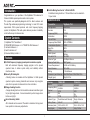
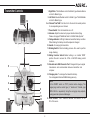
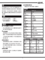
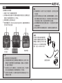
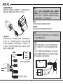
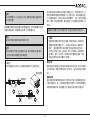
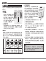
1
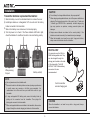
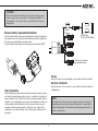
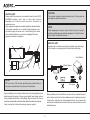
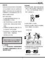
TS4
2.4 GHz DIGITAL PROPORTIONAL 4-CH RADIO CONTROL SYSTEM
數 位 式 4動 無 線 展 頻 遙 控 系 統
Instruction Manual操作說明書
Introduction
■ Built-In Mixing Function for V-Tail & ELEVON
2 additional mixing functions- V-Tail and Elevon can be selected to
fit your model.
Congratulations on your purchase of the SkyMaster TS4 advanced 4
Channel 2.4GHz spread spectrum radio control system.
This system was specifically-designed with the latest wireless and
Thunder Tiger advanced-programming technology to meet R/C model
requirements. With spread spectrum and smart frequency-hopping
system, the SkyMaster TS4 radio system delivers precision & reliability
control without any interference risks.
Specifications
Transmitter
Configuration
Encoder
Frequency(GHz)
Modulation
Current Drain
Frequency Band Width
Transmission System
Band No.
ID No.
Radio Speed
Simulator Port
Antenna Type
Antenna Peak Gain
Power Requirement
Servo Reverse
Mixing
Dimension (w/o Antenna)
Weight (g/oz)
System Contents
1) SkyMaster TS4 Transmitter x 1
2) TRS601DD 6CH Receiver x 1 or TRS401SS 4CH Receiver x 1
3) Instruction Manual x 1
4) Switch Hardness l x 1
5) Receiver Battery Holder x 1
Features
■ 2.4GHz Frequency hopping spread spectrum wireless system
Built with advanced frequency hopping program on the spread
spectrum base to deliver system safety and reliability without
interference risks.
■ Security ID binding link
A binding feature is included with the SkyMaster 2.4 GHz spread
spectrum system ensuring transmitter and receiver only recognize
each other to prevent interferences from other controllers.
■ Range checking function
A range checking button on the transmitter reduces transmitter signal
for pre-flight range check. It is recommended to perform range check
before every flight.
■ Servo Reversing Switch
All 4 channels can be reversed. The switch is located on the top panel
lower position to make easy adjustments.
Receiver
Item No.
Frequency(GHz)
Channel
BEC
Type
Antenna Type
Battery Power
Dimension(mm)
Weight(g/oz)
1
SkyMaster TS4
Dual Sticks
4Ch
2.4GHz
GFSK
[email protected]
2402~2479MHz
FHSS
78CH
13bit
16Kbps
Mini USB
1/4λDipole Sleeve
2dBi Typical
9.6V/8 cell AA Battery
CH1~CH4
V-Tail & Elevon
180x180x70mm/7.08x7.08x2.76in
435g/15.37oz
TRS601DD
AQ2257
2.4GHz
6CH
No
PPM
Dual Antenna & Diversity
4.8~6V
29.2 x 44.9 x 14.1
10.5g / 0.37oz
TRS401SS
AQ2280
2.4GHz
4CH
No
PPM
Single Antenna
4.8~6V
35.6 x 18.3 x 14.2
6.5g / 0.23oz
Transmitter Controls
1. Right Stick: Throttle/Aileron control for Mode1 type. Elevator/Aileron
control for Mode 2 type.
2. Left Stick: Elevator/Rudder control for Mode1 type. Throttle/Rudder
control for Mode 2 type.
3~6. Channel Trim TAB: Trim tabs to trim the control to neutral position
for corresponding servos / channel.
7. Power Switch: Turn the transmitter on or off.
8. Antenna: Adjust the antenna to proper direction before flying.
Please refer page 9 ”Addittional Note for 2.4GHz Radio System”.
9. Voltage Indicator: LED light indicates transmitter battery condition.
When blinking, the battery should be replaced / charged.
10. Handle: For carrying the transmitter.
11. Binding Switch: Performs binding process. Also used to perform
range checking.
12. Mixing Function Switch: Default setting is on middle “NOR”
position. Re-set to access the V-Tail or ELEVON mixing control
functions.
13. Simulator mini USB Connector Port: Designed for by-wire signal
transmission and communication between transmitter and
computer.
14. Charging Jack: To recharge the transmitter battery.
For rechargeable Nicd and NiHM battery pack only.
13
8
9
10
3
5
2
1
4
6
7
11
14
12
NOTE
Set the ON/OFF switch on “OFF” position before charging. The
charger plug must be correct type (“+” inside and “-“outside, type
TAMIYA N-3U or equivalent). Using the wrong type may explode,
causing personal injuries and damages.
15. Servo reverse: The 4 switches reverses the direction of the
Ch1~Ch4 servos.
15
2
Installation
CAUTION
a) Do not attempt to charge alkaline batteries, they may explode!!
b) When charging rechargeable batteries, turn off the power switch before
charging. The charger plug must be of the correct type (“+” inside and
“-“outside, type TAMIYA N-3U or equivalent). Incorrect charger plug
type may provoke an explosion, causing personal injuries and
damages.
c) Always ensure batteries are loaded in the correct polarity. If the
batteries are loaded incorrectly, the transmitter may be damaged.
d) When the transmitter is not used for any short / long period of time,
always remove the batteries from the transmitter.
Transmitter batteries replacement/installation:
1) Slide the battery cover in the indicated direction to remove the cover.
2) Install 8pcs alkaline or rechargeable “AA” size cells into the battery
holder connected to the transmitter.
3) Slide on the battery cover and ensure it is locked properly.
4) Turn the power on to check. If the Power Indicator LED fails to light,
check the batteries for insufficient contact or incorrect battery polarity.
HELPFUL HINT
You may also use the NiCd or
NiHM rechargeable cells. They
can be charged through the
charge jack located on the side
of the transmitter. The ACE
2970/2971/2972 Radio battery
conversion kits are
recommended.
Battery cover
While pressing
this part
Battery cell (x8)
NOTE
a) Use only same brand, fresh, alkaline cells.
b) Ensure all contacts in the battery holder are clean by using a pencil eraser
Cord to transmitter
external charging jack
to gently remove any corrosion or dirt that may accumulate. It is
recommended to do this each time you install fresh cells into your
transmitter.
c) If using rechargeable 9.6V battery pack, remove the battery holder by
pulling out the connector from the transmitter. Then plug-in the
battery-pack connector to the transmitter.
d) When rechargeable batteries are installed in the transmitter, these can be
charged through the external charging jack located on the transmitter.
CAUTION
When the transmitter is not used for any short or long period, always
remove the batteries.
3
CAUTION
Ensure the contacts in the battery holder stay clean by using a pencil
eraser to gently remove any corrosion or dirt that may accumulate. It is
recommended to do this each time you install fresh cells into your
battery holder.
Switch
Harness
Receiver battery replacement/installation
Insert 4 fresh AA cells into the receiver battery holder. Ensure the batteries
are loaded in the correct polarity order. Maintain the battery contacts in
the same way as described in previous section.
Insert the switch harness plug into the receiver socket marked "BATT"
R6(AA),LR6
Ni-Cd or Ni-MH Battery
Receiver
Throttle servo used on
gas powered model
Servos
Mount the servos as recommended in your model's instruction manual.
Receiver installation
Note the location of the receiver in your model's instruction manual or
building plans.
Radio installation
Before installing your radio into your model, connect the receiver, servos,
and switch harness/battery pack as shown. In addition to checking for
proper operation, this "bench test" helps you become familiar with the
operation of your radio. Begin by turning on the transmitter, and then turn
on the receiver switch. Make sure that all servos and trims levers are
operating, and take a few moments to "play" with your system. After
completion of your bench testing, turn off the receiver, followed by the
transmitter.
NOTE
We assume that all areas where large currents are flowing are
generating noise, and noise is a type of radio wave. It is important to
reduce the possibility of interference by locating a proper position for
receiver and antenna.
4
CAUTION
HELPFUL HINT
The receiver contains precision electronic parts. These parts are
vulnerable to vibration and shock.
Always install the receiver as far as possible from the motor, ESC,
NiCd/NiMH batteries, motor wire or other noise sources.
Especially, do not route the motor wire next to the receiver or
receiver antenna.
Noise suppression capacitors should be installed on almost all motors.
If the proper capacitors are not installed, high frequency noise
will reduce range and cause loss of control along with various
other problems. Make sure your motor is equipped with noise
suppression diodes or capacitors.
NOTE
When wrapping the receiver, keep in mind that you are trying to
cushion a delicate piece of electronic equipment, so "wrap" the foam,
don't "stretch" it around the receiver.
HELPFUL HINT
A simple way to isolate the receiver from vibration is by attaching it
to the chassis or mounting plate with thick double-sided tape.
Foam Rubber
Rubber Spacer
NOTE
FET servo wire (7.2V) can also generate noise, position them as
far away as possible from the receiver and the antenna.
Two Layers
Space available in your model will determine how much padding can be
placed around the receiver. Choose a good quality foam rubber, such as
those available from Du-Bro, Carl Goldberg, Sig, and others. R/C foam is
made from natural rubber, which eliminates vibration far better than synthetic
foam, (such as the kind used for packing consumer goods).
Many modelers prefer to install their receiver into the model at this point,
with no further protection. Another sizeable group of modelers prefer to go
a step further, and place the foam-wrapped receiver into a plastic bag,
secured with a rubber band around the receiver case as well as the servo
and battery wires.
5
Functions
The advantage of the plastic wrap is the protection against fuel or oil in
the event of a major crash. The disadvantage of the plastic, especially if
you run the model in very hot and humid conditions or wet days, is that
moisture can accumulate inside the receiver.
The SkyMaster TS4 transmitter was specifically-designed to operate air
models. Basic functions for this transmitter are listed below.
1. Power On
CAUTION
a) Turn On/Off
After installing the transmitter
batteries, turn on the transmitter
power by sliding up the switch
located on the front middle
position of the transmitter. The
LED light turns “RED”. To turn off
the power, slide down the switch,
the LED indicator light will turn off.
b) Low Battery Power Warning
If the transmitter battery power is too low, a short “Bi-Bi-Bi…”
warning tone will be emitted and the LED indicator will flash. It’s
very dangerous to fly the model with low battery transmitter.
Please change the batteries immediately.
Any contact with moisture i.e. water or condensation may cause
malfunction and loss of control.
HELPFUL HINT
If you choose to wrap your receiver in both foam and a plastic bag,
it is recommended to periodically remove the receiver from your
model, remove the foam and bag to let the receiver "air out". This
maintenance procedure will let you determine if any moisture is
accumulating in the protective wrap. Small holes cut into the bag will
allow airflow into the receiver, and eliminate the need for the periodic
checks, although you will lose a certain amount of protection against
fuel or oil with this step.
Battery installation
2. Stick Controls
Always wrap the battery pack in foam, and mount it in the location specified
in your models instructions. It is also recommended to wrap the battery
pack in a plastic bag, as its location (close to engine and fuel tank) makes
fuel proofing vital.
The left and right sticks are designed to drive the 4 channels on the
receiver. Both Mode 1 and Mode 2 are available on the SkyMaster
TS4 transmitter. Control functions are indicated below:
Switch installation
Pick the most convenient location for your on/off switch as required by
your particular model. Always mount the switch on the opposite side of the
engine exhaust. After mounting the switch, carefully bundle any excess
servo wires with cable ties, keeping them away from any moving item
(pushrod, servo arm, etc.) that could catch and cut the wires. Any empty
space in your fuselage radio compartment can be filled with excess foam.
Mode
Mode 1
Mode 2
6
Left Stick
Left / Right
Up / Down
Rudder
Elevator
Rudder
Throttle
Right Stick
Left / Right
Up / Down
Aileron
Throttle
Aileron
Elevator
3. Binding process
“Range-Checking” procedure:
a) Turn both transmitter and model power on and ensure the system
is functioning properly.
b) Take the transmitter to a distance of about 20~30m from the
model.
c) Press and hold the “Binding SW” button. Signal strength is now
weak. The transmitter buzzer will signal with a short “Bi-Bi-Bi”
warning tone. Please do not release “Binding SW” at this stage.
d) Operate both left and right sticks to drive movement on the
servos.Visually confirm that all movements are accurate and
signal is interference-free.
e)Release “Binding SW” button. Signal reverses back to full strength
and warning tone stops. And the warning tone also will stop in the
same time.
f) Model is ready to fly.
A binding feature is included in the SkyMaster
TS4 2.4 GHz spread spectrum system to
ensure the transmitter and receiver bind
properly and prevent interference from other
controllers.
To bind Tx/Rx, please proceed as per the
following:
a) Press and hold “Binding SW” button located
on the right lower side of the transmitter.
b) Simultaneously, turn on the power.
c) Release the “Binding SW” button. The binding LED will blink
rapidly, indicating the transmitter is binding.
d) Press and hold the BINDING push button on the Receiver, plug
the battery power connector on the receiver to turn power on.
Then release the BINDING push button.
e) Successful binding is confirmed by the binding LED changing from
a rapid blink to a slow flash on the transmitter. The LED will turn
green on the receiver. Upon confirmation, turn off power of the
receiver and transmitter and launch normal start-up procedures.
NOTE
Never push the “Binding SW” button during flight. Flying under weak
signal strength will result in signal loss and model crash.
NOTE
Binding process may take 3~10 seconds to execute. If binding fails,
the LED light on the receiver will turn red. Please turn off power and
repeat the above steps from a) ~ e).
4. Range-Check
A built-in range-check function on the transmitter reduces signal
strength for pre-flight range-check. When this function is activated,
signal strength is weak. Use the weak signal strength for pre-flight
range-check to confirm operation of wireless radio control system is
normal. It is recommended to perform a complete range-check
before every flight.
7
5. FAILSAFE Function Setting
d) Test by turning off your transmitter and observing the servo failsafe
position activates, next turn off your receiver.
ACE RC TS4 system features a built-in Pre-setting Failsafe function
to automatically set a servo command if the receiver loses the signal
from the transmitter due to interference. For safety, we strongly
recommend to check the FAILSAFE function before flying.
Resetting FAILSAFE
FAILSAFE settings can be reset by pressing the Binding Switch on
your receiver (power on). First, ensure your radio system is bound
properly and proceed as per the following:
a) Power on your TS4 transmitter & Receiver. Move and hold control
sticks to preferred position should a failsafe situation occur
(select any channels from CH1~CH4). Factory pre-settings are
recommended, please refer to “Note”.
Test by turning off your transmitter and watching the
servo failsafe position activate.
e) Switch on the transmitter & receiver again, and ensure that all servos
follow the movements of the sticks before you fly.
f) If fails or need to reset the Failsafe then repeat step a) ~ e).
NOTE
Pre-settings for the FAILSAFE Function are:
■ Throttle at idle position (Throttle stick is at lowest)
■ The other channels are at neutral position.
CAUTION
■ Always check the FAILSAFE function after each binding.
■ Pre-setting will be executed unless you reset the FAILSAFE.
■ FAILSAFE function ALWAYS memorizes the latest settings if
you do not manually reset the FAILSAFE function after a new
system binding.
b) Press & hold the binding switch on the receiver for 4 seconds.
c) When the LED on the receiver starts blinking, release the binding
switch then the LED turns to red for 2~4 seconds then turn back
to green, indicating the function is successfully set.
Press & hold Binding switch...
LED Binding Switch
Receiver
6CH
AQ2257
TRS601DD
Release Binding switch when
flashing in GREEN
Turn to RED
for 2~4 seconds
LED
Receiver
4CH
6. Flying a RC Flight-Simulator
Use a suitable interface device to connect the mini USB port (located
on the back of the transmitter) to a personal computer and directly
on your simulator.
AQ2280
TRS401SS
Binding Switch
Turn back to GREEN
indicating the FS is success
8
FCC Interference Statement
FCC Radiation Exposure Statement:
This equipment complies with FCC RF radiation exposure limits set forth for an
uncontrolled environment.This equipment should be installed and operated with a
minimum distance of 20 centimeters between the radiator and your body.
This transmitter must not be co-located or operating in conjunction with any other
antenna or transmitter.
The antennas used for this transmitter must be installed to provide a separation
distance of at least 20 cm
from all persons and must not be co-located or operating in conjunction with any
other antenna or transmitter.
This equipment has been tested and found to comply with the limits for a
Class B digital device, pursuant to Part 15 of the FCC Rules. These limits
are designed to provide reasonable protection against harmful
interference in a residential installation.
This equipment generates, uses and can radiate radio frequency energy
and, if not installed and used in accordance with the instructions, may
cause harmful interference to radio communications. However, there is
no guarantee that interference will not occur in a particular installation. If
this equipment does cause harmful interference to radio or television
reception, which can be determined by turning the equipment off and on,
the user is encouraged to try to correct the interference by one of the
following measures:
Using Caution at the Flying Field
■ Always perform a pre-flight range-check to ensure conditions are
interference-free.
■ Do not operate the model or use the radio in rain or lightning.
■ Do not operate the model or use the radio if you have been drinking
alcohol or under the influence of any other substance that could affect
your skills and judgment.
■ Always check battery charge before flight.
■ Keep out of reach of children.
■ Do not store the radio in temperatures below -10 ˚C (14˚F) or above
40˚C (104˚F) or in a humid, dusty, or high vibration environment.
■ Keep the radio away from direct sunlight.
■ To prevent corrosion, remove batteries before storing the radio for a
long period.
■ Reorient or relocate the receiving antenna.
■ Increase the separation between the equipment and receiver.
■ Connect the equipment into an outlet on a circuit different from that to
which the receiver is connected.
■ Consult the dealer.
FCC Caution:
To assure continued compliance, any changes or modifications not expressly
approved by the party responsible for compliance could void the user's
authority to operate this equipment. (Example - use only shielded interface
cables when connecting to computer or peripheral devices).
This device complies with Part 15 of the FCC Rules. Operation is subject to
the following two conditions:
(1) This device may not cause harmful interference, and (2) This device must
accept any interference received, including interference that may cause
undesired operation.
Additional Note for 2.4GHz Radio System
CORRECT
CORRECT
WRONG
WRONG
For best operating range, always ensure the largest section of your
transmitter antenna faces the model.
Warning! Operating range may be significantly reduced with the
transmitter antenna pointing directly at the model!
9
Accessories
AQ2280
AQ2257
AQ2257 2.4GHZ 6CH RECEIVER, TRS601DD
AQ2280 2.4GHZ 4CH RECEIVER, TRS401SS
AC2262
2.4G TX ANTENNA, TS6
2707-I
FSU FLYING SIMULATOR USB
INTERFACE
1389-R/-W
NECK STRAP RED/WHITE
AQ1499 SERVO ACCESSORY
PACKAGED FOR S1903
AG2050 AA BATTERY CASE
AC2266
2.4G RX ANTENNA, TRS601DD
8114 ACE RC SERVO, S1903
8117 ACE RC MICRO SERVO, C1016
AQ0089 AAA BATTERY CASE
10
AC6537
2.4G RX ANTENNA, TRS401SS
AQ1496 SERVO ACCESSORY
PACKAGED FOR C1016
AT2139
AT2139-J
AT2140
AT2141
TX/Rx CHARGER, 110V(US)
TX/Rx CHARGER, 100V(JP)
TX/Rx CHARGER, 230V/2P(EU)
TX/Rx CHARGER, 230/3P(UK)
Service
Thank you for purchasing the ACE RC SkyMaster TS4 Radio. This radio
was produced by Thunder Tiger Corp.
Thunder Tiger products are sold worldwide through authorized
distributors supported directly by Thunder Tiger. To receive the latest
product information and enjoy full technical support, please contact your
nearest hobby shop or Thunder Tiger authorized distributor.
2927 Ni-MH BATTERY PACK/FLAT, 2946-I
4.8V/1200mAH 2/3A
Status Indication Chart
Ni-MH BATTERY PACK/FLAT,
9.6V/1100mAH AA
The following chart indicates LED and buzzer status. Do not operate your
model if you suspect your radio is not working properly. If you encounter
a signal not indicated on this chart and can not solve the problems by
yourself, please contact your local Thunder Tiger authorized distributor
for service.
Status
AG2051 SWITCH HARDNESS W/O CHARGING CORD
2970 Ni-MH BATTERY KIT(12pcs),w/110V CHARGER
2971 Ni-MH BATTERY KIT(12pcs),w/230V/2P CHARGER
AG2078 SWITCH HARDNESS W/O CHARGING CORD 2972 Ni-MH BATTERY KIT(12pcs),w/230V/3P CHARGER
11
Receiver
Power
Buzzer
Binding LED
LED indication
Red/ Solid
Bi
Red/ 1 second
Red/ 1 second
Normal Operation
Red/ Solid
-
Green/ Flashing
Green/ Flashing
Binding
Red/ Solid
-
Binding Success
Red/ Solid
-
Binding Failed
Red/ Solid
-
RF Failed
Red/ Solid
-
Red
Red/ Solid
Assess to the FS setting
Red/ Solid
-
Green/ Flashing
Green/ Flashing
FS Set Processing
Red/ Solid
-
Green/ Flashing
Red/ Solid
FS Success
Red/ Solid
-
Green/ Flashing
Green/Solid
Range Check
Red/ Solid
Bi-Bi-Bi...
Green/ Flashing
Green/Solid
Low Battery
Red/ Flashing
Bi-Bi-Bi...
Green/ Flashing
Green/Solid
Initializing
(when power on)
2969-J/S Ni-MH BATTERY PACK/
2939 Ni-MH BATTERY PACK/
SQUARE, 4.8V/1100mAH AA
SQUARE, 4.8V/1200mAH 2/3A
Transmitter
Green/ Rapid Blink Red/Green Alternate Flashing
Green/ Flashing
Green/Solid
Green/ Rapid Blink Red/Green Alternate Flashing
■ 內建V型尾翼及副翼混控功能
簡介
內建兩種混控功能-可選用V型尾翼及三角型副翼混控。
首先感謝您購買 SkyMaster TS4 4 動 2.4GHz 無線展頻遙控系統。此發
射機採用最新的無線傳輸與雷虎先進的程式控制技術,是專為遙控模型
需求所特殊設計。系統結合發射與接收可以互動溝通模式,跳動式頻道
傳輸,使整體無線系統的傳輸控制展現精準穩定的特性也無須擔心頻率
干擾的問題。
基本規格表
內容物
1) SKYMASTER TS4 發射機 X 1
2) TRS601DD 6動接收機 X1或
TRS401SS 4動接收機 X1
SkyMaster TS4
雙桿板控
4動
2.4GHz
GFSK(PPM)
[email protected]
2402~2479MHz
FHSS(跳躍展頻)
78 個
13 bit
16Kbps
Mini USB
1/4λ同軸偶極天線
典型2dBi
9.6V/8 cell AA 電池
1~4動
V型尾翼及三角型副翼
180x180x70mm/7.08x7.08x2.76in
435g/15.37oz
發射機
機型
動作數
使用頻率 (GHz)
模組
輸出電流
頻寬
傳輸系統型式
頻道數
ID(認證號)數
傳輸數度
訊號傳輸接頭
天線形式
天線最高增益
電源
逆轉功能
混控功能
尺寸 (不含天線)
重量 (g/oz)
3) 說明書 X 1
4) 開關組 X 1
5) 接收機電池盒 X 1
特點敘述
■ 2.4GHz 無線跳躍展頻(FHSS)遙控系統
採用先進的無線跳躍展頻(FHSS)技術,使整個無線控制系統的操作更
加安全可靠並不會有被干擾的危險。
■ 安全認證校頻連接
在啟動無線操控之前,須先進行發射與接收之間特殊的安全對頻配對
認證程序,然後發射與接收模組便會認可所連接成功的認證配對號碼
,所以即使有其他較弱的干擾源產生時,亦不會對已認證配對的發射
接收系統產生干擾。
■ 低發射功率檢測功能
發射機電源開關開啟後,當持續按下右下角對頻配對按鈕時,發射機
的發射功率將轉換成一內定的小發射功率值。利用此小發射功率,可
進行近距離發射接收模組的溝通確認,看是否正常,以確保在長距離
操控時,正常功率亦可操作正常。
■ 伺服機正逆轉開關
4動伺服機皆能切換正逆轉功能。位在發射機正面下方位置的開關能
TRS601DD
AQ2257
2.4 GHz
6動
型式
天線型式
電源
尺寸
重量
PPM
PPM
4.8~6V
29.2x44.9x14.1mm
10.5g / 0.37oz
4.8~6V
35.6x18.3x14.2
6.5g / 0.23oz
BEC
讓您更快速容易地進行調整。
12
TRS401SS
AQ2280
2.4GHz
4動
接收機
料號
頻率(GHz)
頻道數
無
無
雙天線及雙接收
單天線
發射機各部位功能簡介
1. 右邊搖桿:在Mode1中是控制油門與副翼的操控,在Mode2中是控制
升降舵與副翼的操控。
2. 左邊搖桿:在Mode1中是控制升降舵/方向舵的操控,在Mode2中是控
制油門/方向舵的操控。
3-6. 微調開關:此微調開關是進行第一動到第四動所控制伺服機中立點位
置的細部調整。
7. 電源按鍵開關:進行發射機的總電源開啟與關閉。
8. 天線:飛行前請參閱第19頁“天線注意事項”,將天線調至適當方向。
9. 電壓顯示LED燈:此LED燈主要是顯示目前發射機電源狀態,正常狀態
下是顯示紅燈,如LED燈開始閃爍,且發射機發出“嗶-嗶-嗶..”
的警告聲則表示發射機電池電壓太低,需立即更換電池。
10. 提把:提供你可輕易的提取發射機。
11. 校頻配對開關:此開關是執行發射接收間的校頻配對功能。
12. 混控模式控制切換開關:設定值為中點位置“正常模式”,可撥接至
V型尾翼或升降舵副翼混控功能。
13. 模擬USB連接插槽:此插槽是設計給發射機對外連結其他裝置(如個人
電腦) 進行訊號的傳輸溝通用。
14. 充電座:利用此開關可以直接進行發射機內可充電電池(如鎳氫、鎳鎘..
等) 的充電。
13
8
9
10
3
5
2
1
4
6
7
11
14
12
注意:
進行充電時,需將發射機電源開關關閉,充電器的選用,必須選擇正確連接
頭型式(“+” 正極在內部,“-”負極在外部)。選擇錯誤的充電器型式會有
爆炸而導致人員受傷的危險。
15. 伺服機逆轉開關:此開關可個別切換第1~4動伺服機正、逆轉方向。
15
13
安裝
警告:
a) 安裝鹼性電池時,絕對不可以進行充電的動作,否則可能造成爆
發射機電池安裝與更換
1) 依圖示方向取下發射機背面電池蓋。
2) 安裝8個AA規格的鹼性或可充電式鎳氫電池到電池座中並將電池座連
炸的危險。
b) 如使用可充電電池並進行充電時,請將電源開關關閉,並使用正
確的充電插頭(插頭內部是正極,外部是負極)如使用正負極型式
不對的插頭進行充電,可能造成爆炸導致人員受傷。
c) 安裝時需確保電池的極性位置使正確的,不正確的安裝可能導致
發射機的損壞。
d) 假如在長時間不使用發射機的狀態下,請將電池自發射機內移除。
接頭插入發射機電池槽中的左上方插孔。
3) 將電池蓋蓋上並確定安裝妥當。
4) 將電源開關打開,假如紅色LED指示燈並未亮起,請重新確定電池極
性方安裝方向是否正確。
小提示
亦可使用充電式鎳鎘或鎳氫電池。
可直接將充電器圓型插頭插入發射
機側邊之充電插孔進行充電。建議
您採用ACE RC出品專用遙控電池
電池蓋
套件,料號:2970/2971/2972。
按住電池蓋
向下滑出
8個AA電池
注意:
a) 請使用全新且同品牌的鹼性電池。
b) 安裝前為確保電池固定座的導電極片是導電良好的,請用小毛刷
連接至發射機
清潔極片可能導致導電不良的髒物或鏽蝕。建議每一次更換電池
時,皆進行清潔程序。
電池盒
c) 假如使用9.6V的可充電電池包,則拿掉電池固定座,然後將電
池包上的連接頭直接插入發射機電池槽左上方的插孔。
d) 如使用可充電式電池,則充電時可直接利用發射機右側邊下方的
充電孔進行充電。
14
1.接收機電池更換/安裝
警告:
將4顆全新的AA(3號)電池放入接收機電池盒中,並確認電池兩極皆已正
確與銅片接觸。將開關上插頭插入接收機上“BATT”插座中。
請務必遵守,使用時、最先開啟發射機電源,使用後、最後關閉發
射機電源的程序。務必牢記並提醒自己,接收機必需在有發射機訊
號的情況下才能開啟。若先關閉發射機可能會讓接收機失去訊號而
使伺服機錯亂過度作動,造成伺服機齒輪受損。
伺服機
請參考您的遙控模型安裝說明書來安裝伺服機。
接收機安裝
請參考您的遙控模型說明書來選擇接收機安裝位置。
注意:
有大量電流通過的介質會對遙控訊號造成干擾。請務必選擇干擾最
小的位置來放置接收機及天線。
2.遙控系統安裝
進行遙控系統安裝之前,請先依照圖示將接收機、伺服機及開關組/電池
進行連接,並試一下各伺服機是否皆正確作動。將系統安裝至模型機體
後,接著打開發射機電源,再打開接收機電源。可多試著操控一下系
統,以確認一下所有伺服機及連桿是否皆能作動。確認完畢,先關閉接
收機電源,再關閉發射機電源。
小提示
請將接收機安裝於遠離馬達、速控器、電池及馬達連接線或其他
會產生干擾訊號的位置,特別注意勿將馬達連接線繞過接收機或
天線。
一般而言,馬達應該都有加裝干擾抑制電容器,若未加裝則可能
會發出高頻干擾使接收距離縮短而造成失控或其他危險。請確認
您所使用的馬達是否已加裝干擾抑制電容。
開關組
R6(AA),LR6
鹼性電池或鎳氫/鎳鎘電池
接收機
油門伺服機(*引擎動力)
15
很多模型玩家對接收機進行的保護工程都僅止於此;我們建議您可進一步
再將套好橡膠保護套的接收機組裝入另一個密封袋中,好處是當模型發生
大力碰撞或墜毀時,也能防止燃油或其他液體滲入;此外,當您在極端環
境中(嚴熱、潮溼或陰雨氣候)操作模型時,也可保護您的接收機防止水
氣滲入。
注意:
FET伺服器線材(7.2V)也會產生干擾,請儘可能裝置在遠離接收機
及天線的位置。
模型機體內實際的空間會影響採取何種防震措施;若接收機放置於密度品
質優良的橡膠套中,將獲得較佳的防震、防潮等保護功能。
注意: 任何液體(如水份或凝結水氣)都可能造成機能失常或失控。
警告:
小提示:
若接收機同時覆有泡棉及密封袋保護,建議您可每隔一段時間後將
整組接收機自模型機體上拆下,並拆除泡棉及密封袋,讓接收機“
風乾”,這個保養步驟可以確保溼氣不會堆積在泡棉或密封袋中。
或亦可在密封袋上打開一些通風孔,就可以不用每隔一段時間就要
進行檢查,當然,如此的話,接收機的安裝位置就更為重要,必需
更詳加考慮燃油或其他液體滲入的問題。
接收機內有易受震動而受損的精密電子元件。
注意:
在對接收機進行防震工程時請特別注意,接收機是敏感的電子零件
,請勿將泡棉過度擠壓塞在接收機周圍。
電池安裝
請將電池組包覆完整並安裝於模型說明書中指定的位置;若安裝位置靠
近引擎或油箱,建議可將電池組裝入密封袋中,以防止燃油或其他液體
滲入。
小提示:
在接收機底座或安裝孔位上加裝雙面泡棉膠就可以有效地防震。
橡膠保護套
開關組安裝
請參考模型說明書將開關組安裝在方便使用的位置。請將開關組安裝於
引擎消音器的另一側,並將相關線材整束固定整齊,以免脫落線影響伺
服機連桿或擺臂作動。模型機體上的若有多餘空間亦可填充防震泡棉。
橡膠墊圈
雙層底板
16
3. 安全配對校頻認證
基本功能說明
在啟動無線操控之前,須先進行發射與接收之間特
殊的安全對頻配對認證程序,然後發射與接收模組
便會認可所連接成功的認證配對號碼,所以即使有
其他干擾源產生時,亦不會對已認證配對的發射接
收系統產生干擾。基本上,附於完成機中的發射機
在出廠前,皆已完成此配對校頻的程序,所以不需
再執行此步驟,但如新購買或其他因素須重新進行
配對校頻,請依照下列步驟執行:
SkyMaster TS4 是特別為操控航空模型所設計的發射機,基本的操作功
能說明於下
1.電源開/關
a) 開啟/關閉
當發射機已正確安裝電池後,將黑色電
源開關上推,此時發射機會發出一短
聲”嗶”的聲響,表示電源已被開啟,且
開關上方的紅色LED燈亦會亮起。關閉
電源時,直接將黑色開關向下推,此
時LED燈熄滅,表示電源已關閉。
a) 先持續按住發射機右下角配對校頻“Binding Switch”開關。
b) 將電源開關上推開啟發射機電源。
c) 將按住右下角配對校頻(Binding Switch)開關放開,同時你會看見配
b) 低電壓警示功能
假設發射機內電池電力不足,則發射機將會發出”嗶-嗶-嗶..”短促
的警示聲響,LED燈亦會轉成閃爍狀態。在低電壓狀態下操控模型是
非常危險的,所以此時應立即更換電池。
對校頻“Binding Switch”開關上方的LED綠燈呈現”快速閃爍”狀
態,表示發射機正在進行配對校頻的狀態。
d) 持續按住接收機上紅色“校頻開關(Binding)”,同時接上電池以打
2. 搖桿控制
開接收機電源。接著再放開校頻開關,發射機與接收端便會自動進
發射機上左右搖桿是執行接收/模型端主要4個控制動作的操控。因操
控習性的不同,所以 SkyMaster TS4 發射機會有2種不同規格的出廠
設定 Mode1 與 Mode2 。不同型式發射機,搖桿的操控相對於各個動
作的控制,說明如下:
行配對校頻的程序,此時接收機端的LED顯示燈會呈現紅/綠燈交替
明滅的閃爍狀態。
e) 配對校頻成功後,校頻開關上方的LED燈便會由綠色快速閃爍顯示
轉成慢速一閃一閃綠燈顯示的狀態。接收機端上的LED顯示燈亦會
顯示成綠燈,然後將接收發射機的電源全部關閉後,在依正確開啟
程序重新進行開機。
型式
Mode 1
Mode 2
左邊搖桿
左/右
上/下
方向舵
升降舵
方向舵
油門/攻角
注意:
一般較頻的時間大約3~10秒,假如配對校頻失敗,則接收機上的LED燈會顯
示紅燈,發射機校頻LED仍持續顯示快速閃爍綠燈,請關機並重新執行上述
a) ~e) 的步驟,重新執行此配對校頻的程序。
右邊搖桿
左/右
上/下
副翼
油門/攻角
副翼
升降舵
17
4. 低發射功率檢測
設定安全回復功能
a) 開啟TS4發射機及接收機電源。撥動欲設定伺服機之對應撥桿至適當
位置並固定,此處即為安全回復啟動時,伺服機會自動執行之動
作。(可由CH1~4中任選1或多個對應伺服機動作;建議您參照“注
意事項”之出廠預設值進行設定)。
發射機內部程式設定有此低發射功率檢測的功能,讓使用者在實際飛
行前可以先進行短距離的測試。當執行此功能時, 發射機的發射功率將
被調整設定至一低發射功率的設定值, 讓你可以執行短距離低功率的檢
測以確保實際飛行時,正常功率在長距離的遙控控制上的安全性。強烈
建議在每次飛行前都需執行此檢測的程序。
請依照下列步驟執行此檢測功能
a) 依正常開機程序開啟發射機與直昇機(接收機)並確定一切正常。
b) 將發射機拿離直昇機約20~30公尺的距離。
c) 持續按下發射機上配對校頻(Binding Switch)的開關,此時發射功率
會被切換至低功率的設定,同時發射機一會發出短促“嗶-嗶-嗶-”
b) 按住接收機上對頻鍵4秒,進入FS設定模式。
的警告聲。
c) 當接收機上綠色LED開始閃爍時,放開對頻鍵,此時LED會轉變為紅
色約2~4秒,後轉變為綠色,表示功能已設定完成。
d) 同時移動發射機上的搖桿來驅動直升機上各相關的拉桿控制,檢測
看一切是否移動正常,是否有不正常抖動的現象。
按住接收機上對頻鍵...
e) 將按住配對校頻(Binding Switch)的開關的手指移除,則發射功率將
LED 對頻鍵
恢復正常同時“嗶-嗶-嗶-..”的警告聲亦會消除。
f) 此時便可開始進行正常的飛行操控。
LED
接收機
接收機
6CH
注意:
AQ2257
TRS601DD
AQ2280
TRS401SS
4CH
對頻鍵
不可在實際飛行中按下配對校頻 ( Binding Switch ) 開關將發射功率
調低,否則低發射功率將導致模型可能失去訊號墜機而造成危險。
綠色LED開始閃爍時,
放開對頻鍵
5. FAIL- 安全回復功能
ACE RC TS4 系統內建安全回復功能,可設定當接收機因干擾或斷電
而失去發射機訊號時,伺服機自動回復至預設位置。安全起見,強烈
建議您務必啟用安全回復功能。
LED會轉變為
紅色約2~4秒
轉變為綠色,
表示功能已設定完成
d) 將發射機電源關閉測試啟動功能之效果,請觀察伺服機是否依預設
之安全回復位置作動。確認完畢請關閉接收機電源。
將發射機電源關閉測試啟動功能之效果,請觀察伺服機是否依預設之安全回復位置作動。
18
e) 若作動不正確或需要調整安全回復位置,請重覆上述步驟 a) ~ e)。
在飛行場地需特別注意的事項
f) 再次依序開啟發射機及接收機,在飛行前請確認所有伺服機作動皆
正確對應撥桿動作。
■ 為避免干擾影響無線控制系統,飛行前接需進行短距離低發射功率檢
注意事項:
本產品出廠預設FS功能如下:
■ 油門伺服機回復至怠速位置。(油門撥桿於最低點)
■ 其他通道皆回復到中立點。
■ 在雨天、閃電或不良氣候,不可以使用發射機操控模型。
測。
■ 在喝過酒或身體不適而對你的操控技術有影響的情況下,不要操控遙
控模型。
■ 操作前一定須先進行發射機電力檢測。
警告:
■ 請放置在小孩不易拿取的位置。
■執行對頻程序後,請務必確認安全回復功能。
■ 發射機不要存放在低於-10℃(14℉)或高於40℃(104℉)的環境,或貯
■若未自行設定安全回復功能,則此功能會被設定在出廠預設值。
■ 存於濕氣過重,灰塵多或震動過大的環境中。
■執行對頻後,若末重新設定安全回復,則會記憶最近一次的設定值。
■ 避免長期置於陽光直射的位置。
■ 為避免電池損壞,長期不使用的狀況下,需將電池從發射機內取下移
除。
6. 飛行模擬軟體的連接
當欲使用此遙控器於電腦上進行飛行模擬軟體的操作時,首先需選用
天線注意事項
適當的連接介面裝置,一端連接至電腦,另一端與 SkyMaster TS4 後
方的小 USB 插槽連接,那便可以以此發射機操控以安裝於電腦上的模
擬飛行軟體。
發射機使用注意事項
CORRECT
CORRECT
WRONG
■ 經型式認證合格之低功率射頻電機,非經許可,公司、商號或使用者
■ 以天線最大面積對正模型,可獲得最佳的遙控距離。
均不得擅自變更頻率、加大功率或變更原設計之特性及功能。
■ 低功率射頻電機之使用不得影響飛航安全及干擾合法通信;經發現有
警告! 天線頂端直指模型會嚴重縮短遙控距離!
干擾現象時,應立即停用、並改善至無干擾時方得繼續使用。
■ 前項合法通信,指依電信法規定作業之無線電信。低頻率射頻電機需
忍受合法通信或工業、科學及醫療用電波輻射信電機設備之干擾。
19
WRONG
選用相關配件
AQ2280
2.4GHZ 4 動接收機,TRS401SS
AQ2257
AC2262 2.4G 發射機天線
2.4GHZ 6 動接收機,TRS601DD
AC2266
AC6537
TRS601DD 2.4G 接收機天線 TRS49SS 2.4G 接收機天線
1389-R/-W 發射機吊帶 紅/白 8114 ACE RC S1903 伺服機
8117 ARC RC C1016 迷你伺服機
2969-J/S 4.8V/1100mAH AA
2939 4.8V/1200mAH 2/3A
2927 4.8V/1200mAH 2/3A
2970 電池(12顆)附Tx/Rx充電器,110V/2P
2971 電池(12顆)附Tx/Rx充電器,230V/2P
2972 電池(12顆)附Tx/Rx充電器,230V/3P
鎳氫電池包
2707-I 模擬器連接線
鎳氫電池包
AQ1496
C1016 迷你伺服機擺臂組
AG2051
AQ1499 S1903伺服機擺臂組
AQ0089 AAA型電池盒
鎳氫電池包
AG2050 AA型電池盒
20
開關組
AG2078 Futaba插孔關關組
2946-I
9.6V/1100mAH AA
鎳氫電池包
AT2139
TX/Rx 發射機充電接頭,110V(US)
AT2140
TX/Rx 發射機充電接頭,230V/2P(EU)
AT2139-J TX/Rx 發射機充電接頭,100V(JP)
AT2141
TX/Rx 發射機充電接頭,230/3P(UK)
售後服務
首先感謝您購買SkyMaster TS4發射機,此發射機是由雷虎科技所生產製
造。在遙控模型領域中,雷虎科技一直致力於高品質產品與最佳服務的
提供。
SkyMaster TS4 在產品上市前,已經過全世界的嚴苛的測試以確保產品
性能與品質。SkyMaster產品在全球皆有正式授權的代理商可提供完整的
產品技術諮詢與售後維修等服務。如欲取得SkyMaster相關最新的產品資
訊或技術服務等,請聯絡全球各地區雷虎所授權的經銷商或模型店。
操作狀態與顯示燈號對照表
下方表格顯示發射機一般正常的操作狀態與相對的顯示燈號與警示蜂鳴
器。當發現發射機工作不正常,請不要使用操控遙控模型。當發現有不
同於下表所列的顯示訊號而無法自行解決時,請聯絡雷虎科技所授權的
代理商尋求產品維修服務。
狀態
接收機
發射機
電源燈
聲響
開啟電源時
恆亮紅燈
短促“嗶”聲響
紅燈1秒
紅燈1秒
正常操作中
恆亮紅燈
-
慢閃綠燈
慢閃綠燈
對頻中
恆亮紅燈
-
快閃綠燈 慢閃紅綠燈
對頻成功
恆亮紅燈
-
慢閃綠燈
對頻失敗
恆亮紅燈
-
快閃綠燈 慢閃紅綠燈
發射模組失效
恆亮紅燈
-
紅燈
恆亮紅燈
進入安全回復設定模式 恆亮紅燈
-
慢閃綠燈
慢閃綠燈
安全回復設定未完成
恆亮紅燈
-
慢閃綠燈
恆亮紅燈
安全回復設定完成
恆亮紅燈
-
慢閃綠燈
恆亮綠燈
低功率檢測
恆亮紅燈 短促連續“嗶”警告聲
慢閃綠燈
恆亮綠燈
低電壓
閃爍紅燈 短促連續“嗶”警告聲
慢閃綠燈
恆亮綠燈
對頻燈 指示燈號
恆亮綠燈
21
FCC ID: VEJTT-FHM2P4G-A12
Manufactured by THUNDER TIGER CORP.
www.thundertiger.com
JC6205V2