1
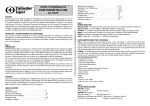
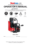
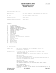
STEELMAX d1
®
OPERATOR’S MANUAL
Portable Magnetic Drilling Machine
WARNING!
BEFORE USE, BE SURE EVERYONE USING THIS MACHINE READS AND UNDERSTANDS
ALL SAFETY AND OPERATING INSTRUCTIONS IN THIS MANUAL.
EYE PROTECTION
REQUIRED
HEARING PROTECTION
REQUIRED
NEVER PLACE
FINGERS NEAR
CUTTING AREA OR
MACHINE ARBOR
LINE VOLTAGE
PRESENT
BEWARE OF
ROTATING
MACHINE PARTS
MODEL #SM-D1
Serial #
Date of Purchase
TABLE OF CONTENTS
Table of Contents . . . . . . . . . . . . . . . . . . . . . . . . . . . . . . . . . . . . . . . . . .2
Introduction . . . . . . . . . . . . . . . . . . . . . . . . . . . . . . . . . . . . . . . . . . . . . .3
Limited Warranty . . . . . . . . . . . . . . . . . . . . . . . . . . . . . . . . . . . . . . . . . .4
Important Safety Instructions . . . . . . . . . . . . . . . . . . . . . . . . . . . . . . . . . .5--6
Grounding Instructions and Extension Cords . . . . . . . . . . . . . . . . . . . . . . . . .7
Special Instructions . . . . . . . . . . . . . . . . . . . . . . . . . . . . . . . . . . . . . . . . .7
Contents of Package . . . . . . . . . . . . . . . . . . . . . . . . . . . . . . . . . . . . . . . .8
Getting Started . . . . . . . . . . . . . . . . . . . . . . . . . . . . . . . . . . . . . . . . . . . .8
Ready for Cutting . . . . . . . . . . . . . . . . . . . . . . . . . . . . . . . . . . . . . . . . . .9
After Cutting . . . . . . . . . . . . . . . . . . . . . . . . . . . . . . . . . . . . . . . . . . . .10
Normal Maintenance . . . . . . . . . . . . . . . . . . . . . . . . . . . . . . . . . . . . . .10
Labels . . . . . . . . . . . . . . . . . . . . . . . . . . . . . . . . . . . . . . . . . . . . . . . . .11
Exploded Views . . . . . . . . . . . . . . . . . . . . . . . . . . . . . . . . . . . . . . . . . .12
Parts List . . . . . . . . . . . . . . . . . . . . . . . . . . . . . . . . . . . . . . . . . . . . . . .13
Wiring Diagram . . . . . . . . . . . . . . . . . . . . . . . . . . . . . . . . . . . . . . . . . .14
TroubleShooting . . . . . . . . . . . . . . . . . . . . . . . . . . . . . . . . . . . . . . . . . .15
Machine Drawings . . . . . . . . . . . . . . . . . . . . . . . . . . . . . . . . . . . . . . . .16
Specifications . . . . . . . . . . . . . . . . . . . . . . . . . . . . . . . . . . . . . . . . . . . .17
Available SteelMax Cutters . . . . . . . . . . . . . . . . . . . . . . . . . . . . . . . . . . .18
STEELMAX DRILLS
AND
CUTTERS, LLC
Tel · 303.690.9146 or Fax · 303.690.9172
6200 S. Troy Circle. Suite 110. Centennial, CO 80111
email · [email protected] / web · steelmax.com
2
SteelMax® d1 Portable Magnetic Drilling Machine
Congratulations on your purchase of a SteelMax portable magnetic drilling machine. SteelMax drilling machines are
designed to deliver fast, efficient hole drilling performance in portable applications. SteelMax drills are
fast becoming the most cost effective and efficient way to drill holes not only at steel fabricating workshops or steel building sites, but also at virtually ever y factor y maintenance workshop, truck manufacturer
& repair company, militar y equipment ser vice, onboard ship maintenance shop etc.
The full advantages of your SteelMax electromagnetic drilling machine can only be achieved with optimal tooling. Milling cutters are designed and manufactured specifically for use with these machines and
offer a wide range of advantages, such as 1.5 inch diameter holes through 2 inch steel, in one pass
and with precision not other wise attainable without heavy stationar y equipment. This performance
advantage has been virtually impossible in a drill with the size and weight of the SteelMax d1 until now.
The SteelMax d1 provides the latest state of the art features in portable drilling equipment. Among the
features are a no-maintenance rail system that eliminates older gib type systems, which lowers
maintenance and maximizes the life of your SteelMax annular cutters. Energy saving and safety features
are also provided through the use of a powerful new generation, low heat electromagnet with
Condensed Magnetic Flux (CMF) and magnetic field control system. This new system provides safety,
energy saving, maintenance, weight and operational advantages over other brand drills.
Please take a moment to complete and mail your product warranty registration
card. Doing so will validate your machine’s warranty period and ensure prompt
service if needed .
3
L IMITED WARRANTY
SteelMax Drills and Cutters, L.L.C. (SteelMax) will, within twelve (12)
months from the original date of purchase, repair or replace any
goods found to be defective in materials or workmanship, provided
the product warranty registration card has been returned to SteelMax
within thirty (30) days of purchase date. This warranty is void
i f tool h a s b e e n d a m a g e d b y accident, neglect, improper ser vice,
or other causes not arising out of defects in materials or workmanship.
This warranty does not apply to machines and/or components which
have been altered, changed, or modified in any way, or subjected to
use beyond recommended capacities and specifications. All
goods returned defective shall be returned prepaid freight to
S t e e l M a x , w h i c h s h a l l b e t h e b u y e r ’s s o l e a n d exclusive remedy
for defective goods. In no event shall SteelMax be liable for loss or
damage resulting directly or i n d i r e c t l y f r o m t h e u s e o f
merchandise or from any other cause. SteelMax is not liable
f o r a n y c o s t s i n c u r r e d o n such goods or consequential damages.
No officer, employee or agent of SteelMax is authorized to make oral
representations o f f i t n e s s f o r a n y p a r t i c u l a r p u r p o s e o r t o w a i v e
any of the foregoing terms of sale and none shall be binding
on SteelMax.
STEELMAX DRILLS AND CUTTERS, LLC RESERVES THE RIGHT TO MAKE
IMPROVEMENTS AND MODIFICATIONS TO DESIGN WITHOUT PRIOR NOTICE.
4
IMPORTANT SAFETY INSTRUCTIONS
WARNING!
WHEN USING ELECTRIC TOOLS, BASIC SAFETY PRECAUTIONS SHOULD ALWAYS BE FOLLOWED
TO REDUCE RISK OF FIRE, ELECTRIC SHOCK AND PERSONAL INJURY.
READ AND SAVE ALL INSTRUCTIONS FOR FUTURE REFERENCE.
1. Never Remove Swarf With Bare Hands
• Use a tool designed for the job to avoid injuries.
2. Never Touch Spindle During Operation
• Cutters are extremely sharp and cause serious injuries.
3. Keep Work Area Clean
• Cluttered areas and benches invite injuries.
4. Consider Work Area Environment
• Do not expose power tools to rain.
• Do not use power tools in damp or wet locations.
• Keep work area well lit.
• Do not use tool in presence of flammable liquids or gases.
5. Guard Against Electric Shock
• Prevent body contact with grounded surfaces. For example: pipes, radiators, ranges and refrigerator enclosures.
6. Keep Children Away
• Do not let visitors contact tool or extension cord.
• All visitors should be kept away from work area.
7. Store Idle Tools
• When not in use, tools should be stored in a dry, high and locked-up place, out of reach of children.
8. Do Not Force Tool
• It will do the job better and safer at the rate for which it was intended.
9. Use Right Tool
• Do not force a small tool or attachment to do the job of a heavy-duty tool.
• Do not use tool for unintended purpose.
10. Dress Properly
• Do not wear loose clothing or jewelry. They can be caught in moving parts.
• Rubber gloves and non-skid footwear are recommended when working outdoors. Never wear gloves near
rotating machine parts.
• Wear protective hair covering to contain long hair.
11. Use Safety Glasses and Hearing Protection
• Also use face or dust mask if cutting operation is dusty.
12. Do Not Abuse Electrical Cord
• Never carry tool by cord or yank it to disconnect from receptacle.
• Keep cord from heat, oil and sharp edges.
5
IMPORTANT SAFETY INSTRUCTIONS ( CONT.)
13. Secure Work
• Use clamps or a vise to hold work. It’s safer than using your hand and it frees both hands to operate tool.
14. Do Not Overreach
• Keep proper footing and balance at all times.
15. Maintain Tools With Care
• Keep tools sharp and clean for better and safer performance.
• Follow instructions for lubricating and changing accessories.
• Inspect tool cords periodically and if damaged, have repaired by authorized service facility.
• Inspect extension cords periodically and replace if damaged.
• Keep handles dry, clean, and free from oil and grease.
16. Disconnect Tools Prior to Service
• Unplug when not in use, before servicing, and when changing accessories, such as blades, bits and cutters.
17. Remove Adjusting Keys And Wrenches
• Form habit of checking to see that keys and adjusting wrenches are removed from tool before turning it on.
18. Avoid Unintentional Starting
• Do not carry a plugged-in tool. Always disconnect from power source before moving.
• Be sure switches are off before connecting to a power source.
19. Outdoor Use Extension Cords
• When tool is used outdoors, use only extension cords intended for use outdoors and so marked.
20. Stay Alert
• Watch what you are doing. Use common sense. Do not operate tool when you are tired.
• Do not use when taking medications that may cause drowsiness.
21. Check For Damaged Parts
• Before further use of the tool, a guard or other part that is damaged should be repaired and performance
verified prior to operation.
• Check alignment of moving parts, binding of parts, breakage of parts, mounting, and any other conditions
that may affect its operation. A guard or other part that is damaged should be properly repaired or replaced
by an authorized service center.
• Do not use this tool if switches do not turn it on and off. Have defective switches replaced by authorized
service center.
22. Never Operate Drill In An Explosive Environment
• Sparks are generated internally by the motor brushes during normal operation.
6
GROUNDING INSTRUCTIONS
The d1drill must be plugged into a three prong outlet, properly installed and
grounded in accordance with all codes and ordinances. The plug and outlet
should look like those in diagram. If in doubt of proper grounding, contact a
qualified electrician.
WARNING!
A shock hazard can result from improperly connecting the grounding wire.
Do not modify the electrical plug provided with tool. Never remove the
grounding prong from the plug. If the cord or plug is damaged, have it
repaired before using. If the plug will not fit the outlet, have a proper outlet
installed by a qualified electrician.
WARNING!
DO NOT USE STEELMAX DRILLING MACHINES ON SURFACES OR MATERIALS BEING
WELDED. DOING SO CAN RESULT IN PERSONAL INJURY AND /OR DAMAGE TO THE DRILLING
MACHINE.
EXTENSION CORDS
Use only 3-wire extension cords that have 3-prong grounding-type plugs and 3-pole receptacles. Make sure
extension cord is in good condition. Replace or repair damaged cords.When using an extension cord, limit
length to 50ft. or less. Only use a cord of 12 gage or larger diameter. An undersized cord will cause a drop in line
voltage resulting in loss of power and overheating. If in doubt, use the next heavier gauge. The smaller the gauge
number, the heavier the cord.
SPECIAL INSTRUCTIONS
1. Read and follow operator’s manual thoroughly. Instructions are intended as a guide in safe operating
procedures and practices. Always contact SteelMax in the event any instruction is not clearly understood.
2. Never wear loose clothing or gloves when working near cutting area or machine arbor.
3. DO NOT touch rotating cutter or machine parts.
4. DO NOT use dull or broken cutters.
5. To reduce the risk of electrical shock, DO NOT remove or alter electrical panels or use machine in damp
areas.
6. Always stop machine completely and unplug from power source before changing cutters, clearing swarf,
filling coolant reservoir or performing maintenance.
7. Always wear eye protection. Any tool can shatter.
8. Always use safety strap provided with machine.
9. Always use proper tooling. Keep cutters securely fastened.
10. Beware of ejected slugs core at end of cut. They become HOT during the cut.
11. Keep all safety features functioning and working properly.
12. Use only authorized service centers for repairs.
7
OPERATING INSTRUCTIONS ( BEFORE YOU BEGIN )
Remove all contents from packaging and inspect to ensure no damage was incurred during shipping.
Your SM-d1 package should include the following:
#
C31272-220-00-00
SS-D1-27
H00643-504-01-00
LIT-015
C31249-010-50-00
C31272-120-00-00
DESCRIPTION
PART
METAL TOOL BOX
SAFETY STRAP
HEX WRENCH 4
OPERATORS MANUAL
SPOKE HANDLE WITH KNOBS
CHIP GUARD
BE
QTY
1
1
1
1
3
1
CAUTION!
SURE YOUR SM-D1 IS DISCONNECTED FROM THE POWER SOURCE BEFORE MAKING ADJUSTMENTS.
1. Assemble (3) spoke handles (item 05) to the pinion hub (item 01.02) NOTE: Pinion assembly is mounted on
the left side of the machine frame. If necessary, it can be reversed to operate from the right side of the
frame. To do so, remove the external retaining ring (item 01.08) from the right edge of the pinion. Using a
5mm wrench (not supplied) loosen the guide rail hex socket retaining bolts about 2-3 turn each (item 19)
just enough for the pinion shaft to slide out of the machine frame without hitting the gear rack (item
02.01.02). Insert the pinion assembly from the opposite side of machine frame. Reassemble in reverse
order and tighten all fasteners securely.
WHAT YOU SHOULD KNOW BEFORE YOU DRILL
1. Type of material to be drilled, Brinnell or Rockwell hardness, material thickness and position should all be
determined to ensure proper selection of SteelMax cutting tools.
2. Remove any excessive scale or rust from surface to be drilled.
3. When drilling thin materials, SteelMax recommends placing a steel plate under the work piece and d1
magnet area to increase magnetic holding force. Failure to do so may result in dangerous operation.
4. Material that has been flame cut may become heat treated and therefore difficult to drill. Avoid drilling near such
areas whenever possible.
5. Paste type cutter lubricant is available for using the d1 drill and annular cutters in the horizontal or inverted
position. Consult you distributor for more information.
Caution: Do not drill on material where welding is also simultaneously being performed. Drilling
machine will be damaged.
Caution: Powering drilling machine from generator without proper surge protection device
between generator and drilling machine may cause damage to the circuitry in machine.
8
READY TO MAKE THE CUT
1. Insert the annular cutter in to the machine arbor, lining up the flats on the cutter shank drive with the set
screws on the arbor. Secure the set screws making sure the screws are recessed in arbor body.
2. Fill the coolant reservoir with a water-soluble coolant. Do not overfill! If drilling horizontally or inverted, use coolant
paste.
3. Position the d1 drill on the work surface. Always use safety strap to prevent injury. Refer to the drawing
below.
4. Lower cutter to surface of material. Turn on coolant flow valve. Coolant flow will start when pilot pin is
depressed. Lifting pilot pin off work surface will stop coolant flow. Always remember to close valve when not
in use.
5. Position chip guard toward work area before drilling.
6. Place the drilling machine on the work piece, with pilot pin over the center of the hole to be cut.
7. Move the magnet “ON” switch to the ON position. The switch will illuminate to indicate DC
power is going to the magnet.
8. Depress motor “ON” switch to start drill. If drill
momentarily turns on but will not continue to run,
check to make certain material is thick enough.
Insufficient thickness can cause magnet to loose hold,
causing an operator hazard. If necessary, clamp an
additional section of steel to the work-piece to
increase magnetic adhesion. If material thickness is
less than 3/16” (5mm), the magnetic field control
system will not allow motor to start. This system will
turn OFF the motor after even minor movement of
magnetic base. If holes must be made regularly in thin (less than 3/8”) material, the magnetic field control
system can be disabled permanently. (Consult Factory)
*Operational Note: Models manufactured after 11-2006 have an electronic overload feature. If the drill
experiences over-current due to excessive cutter penetration speeds, the circuit will stop the drill motor. If this
should occur, simply reset the motor switch to the off position and then turn back on. Proceed with a slower
feed rate without forcing the cutter.
9
CAUTION!
A N A LTERNATE MEANS MUST BE USED TO SECURELY HOLD THE DRILL IN PLACE.
FAILURE TO DO SO CAN RESULT IN SERIOUS INJURIES!
9. To start a cut, apply pressure until the cutter has established an external grove. Continue with steady
pressure through the remainder of the cut (Note: Do not peck drill when using annular cutters). The tools
are designed to evacuate chips when drilling.
AFTER THE CUT
CAUTION! SLUG IS EXTREMELY HOT!
1. After the cut has finished, the slug should automatically eject from the cutter*. Slug can eject with significant
force due to the pilot pin spring pressure. Always be prepared for the ejected slug.
2. Return motor to the full upright position, depress motor OFF button and wait until motor fully stops. Move
magnet switch to the OFF position to release the magnetic base from the material.
*Note: If the slug does not eject after the cut, disconnect the machine from the power source and remove
the cutter from the arbor body, then expel the slug. (Caution: Do not use the pilot pin as damage can result).
NORMAL MAINTENANCE
1.
The SteelMax d1 drilling machine is equipped with new unique system for elimination of excess play in
slide guides.This rail guide system completely eliminates maintenance or adjustment.
2.
After every 250 hours of operation, check the condition of the carbon brushes (03.01.07). If their length is
less than 5 mm they should be replaced with new ones. Replacement of brushes is possible without
removal of motor from the drill.To replace the brushes, remove the 4 screws
(03.01.09) securing the motor field frame cover (03.01.03). Remove the 2 brush holder screws (03.01.10)
and carefully remove the brushes. Reverse the procedure to re-install. After replacement, new brushes
should be run-in without load for about 20 min. Other repair work should only be performed by authorized
service centers. Replacement of brushes is possible without removal of motor from the drill.
3.
To prevent the machine from rusting (especially when used outdoors) all steel parts should be covered
with thin layer of grease film.
4.
Keep the magnet clean and free of chips, oil or other contaminant's.
5.
Occasionally check the magnet base for flatness to ensure proper magnetic holding force.
6.
Replace any worn parts and tighten fasteners that become loose during normal usage.
10
SteelMax® d1 Portable Magnetic Drilling Machine Labels
The figure below shows all labels included on the d1 drilling machine. As a required item for
machine safety, contact the factory for replacement labels if they become damaged.
WARNING !
01.09
03.06
Read the Operation Manual before starting.
Keep your hands away from rotating machine’s parts.
Always stop machine completely and disconnect
from power source before changing cutters,
clearing chips, refilling lubricant and servicing
electrical components.
Always use the safety strap and chip guard.
Beware of ejected slug at end of cut.
Do not remove chips with bare hands. Use special
hook or hand brushes.
Always use personal protection dress, protection
glasses, protection gloves and ear protectors.
Do not use altered, dull or broken cutters.
Protect the power cord from fire, oil and sharp edges.
Use only authorized service centers for repairs.
TM
MAGNET
350
I
04.02
O
RPM
920 Watt
Motor Power
Power Supply
Serial Number
03.03
120 Volt / 60 Hz
TM
MOTOR
TM
www.steelmax.com
11
E XPLODED V IEWS
12
SteelMax® d1 Parts List
Item
01.01
01.02
01.03
01.04
01.05
01.06
01.07
01.08
02.00*)
02.01
02.01.02
02.01.05
02.01.09
02.02.02
02.02.03
02.02.04
02.02.05
02.02.06
02.03
02.04
02.07
02.08
02.09
03.00
03.02.03*)
03.04
03.08
03.09
03.10
03.11
03.12
03.13
04.00
04.01
04.03
04.04
04.05
04.06
05
07
08
10
11
12
13
14
15
16
17
18
19
20
21
22
24*
Description
Part Number
MAIN BODY ASSEMBLY
PINION SHAFT ASSEMBLY
D-RING STRAP
ELECTROMAGNETIC BASE
STRAIN RELIEF PG7
HEX SOCKET BOLT M6X25
SPRING WASHER 6,1
EXTERNAL RETAINING RING 28z
GEARBOX ASSEMBLY
GEARBOX HOUSING ASSY. W/SPINDLE
GEAR RACK
BEARING 608 2Z
HEX SOCKET BOLT M6X20
PLUNGER
SPRING
SEAL
INTERNAL RETAINING RING 19W
HEX SET SCREW M8X10
PINION SHAFT ASSEMBLY
COOLANT VALVE
GUIDE
BRAKE
BRAKE SPRING
MOTOR ASSY. 115V (W/ ARMATURE)
ARMATURE 115V (ASSY. W/BEARINGS
SELF TAPPING SCREW 3.9X19
PROTECTIVE SPRING
FIELD FRAME COVER
BRUSH HOLDER
MOTOR BRUSH
MOTOR BRUSH PLATE
SELF TAPPING SCREW 2.9X5
CONTROL PANEL ASSY. 115V
PANEL PLATE
ELECTRONIC CONTROLLER SW-31 /115V
MOTOR ON/OFF SWITCH 115V
MAGNET SWITCH
LOCKING PILLAR
SPOKE HANDLE INCL. KNOB ASSY.
PLUG
PLUG WITH THREAD
BOTTLE ASSY.
CROSS RECESSED SCREW M4X16
CHIP GUARD
POWER CORD / 115V
STRAIN RELIEF PG11
CROSS RECESSED SCREW M4X10
WASHER, EXT. METRIC 4.3DIN 6798
HEX NUT M4
SPRING WASHER 4,1
HEX SOCKET BOLT M-6X35
SELF TAPPING SCREW 4.8X32
SELF TAPPING SCREW 4.8X50
METAL BOX
HEX WRENCH 4
13
C31272-010-10-01
C31271-010-20-01
C31272-010-30-00
C31271-010-40-01
H01131-133-01-04
N18230-206-20-02
N18200-806-01-01
N18511-110-28-00
C31272-020-00-03
C31272-020-10-01
C31271-020-10-21
H00636-448-01-00
N18230-206-20-00
C03381-390-00-21
C31271-020-20-30
C31279-020-10-60
N18511-120-19-00
N60091-308-10-00
C31271-020-30-01
C31272-020-40-00
C31271-060-00-01
C31271-090-10-01
C31271-110-00-01
C31272-030-00-03
H01111-200-01-02
N18310-630-91-91
C32257-020-30-00
C31272-030-10-30
C31271-030-60-00
H01111-200-01-08
C31271-030-70-00
N18310-620-90-90
C31272-040-00-04
C32257-040-10-00
C31257-041-00-00
WLC-000005
H01115-168-01-01
H01262-003-01-01
C31249-010-50-00
C31271-070-00-00
C31271-080-00-00
C31272-100-00-00
N18221-204-16-00
C31272-120-00-00
C02180-750-05-10
H01131-133-02-02
N18220-204-10-01
N18202-404-03-00
N18214-404-00-01
N18200-804-01-01
N18230-206-35-01
N18310-640-83-21
N18310-640-85-01
C31272-220-00-00
H00643-504-01-00
Qty
1
1
1
1
1
3
3
1
1
1
1
1
1
1
1
1
1
2
1
1
2
2
1
1
1
6
1
1
2
2
2
2
1
1
1
1
1
3
3
2
2
1
1
1
1
1
4
1
2
1
4
3
1
1
1
SteelMax® d1 Wiring Diagram
SteelMax d1 Drilling Machine wiring diagram
14
BASIC TROUBLESHOOTING
1. Motor will not stay running.
• Magnet circuitry is designed to prevent run cycle in the event material “Hold” by magnet is insufficient.
Clamp additional material beneath magnet to increase hold. “Run” switch may be manually held in to bypass
this safety circuit. If operator chooses to use this “bypass” circuit, extreme caution must be used.
• Models manufactured after 11-2006 have an electronic overload feature. If the drill experiences over-current
due to excessive cutter penetration speeds, the circuit will stop the drill motor. If this should occur, simply
reset the motor switch to the off position and then turn back on. Proceed with a slower feed rate without
forcing the cutter.
2. Magnetic base not holding securely.
• Material is too thin to engage magnet. The minimum necessary thickness is 3/16” (5 mm).
• Surface of material being drilled must be free of chips, debris, rust and mill scale.
• Cutter exceeds machine’s rated capacity.
• Check magnet face for unevenness, nicks and burrs.
• Welding equipment connected to material being drilled.
3. Motor slows when drilling.
• Extension cord is too long or too thin.
• Excessive downforce during drilling cycle will cause motor to slow and overheat.
• Cutter dull.
4. Coolant not flowing.
• Coolant system is gravity dependent, machine must be in an upright position to operate properly.
• Dirt or debris in coolant tank.
• Incorrect pilot pin.
• Vent hole in coolant tank cap blocked.
5. Slugs not ejecting from cutter.
• Lack of coolant causing slugs to expand in cutter bore.
• Incorrect coolant type.
• Incorrect pilot pin.
• Broken pilot pin.
• Dull cutter.
6. Breaking cutters
• Coolant flow must be supplied to interior of cutter.
• Excessive feed pressure being applied.
• Excessive material hardness.
• Drilling stacked materials with incorrect cutter.
• Dull cutters; dull or chipped cutting edges require excessive feed pressure.
7. Oversized or rough holes
• Insufficient coolant flow.
• Excessive feed pressure.
• Dull cutter.
15
d1 Dimensions
16
SteelMax
d1
Dimensions and specifications
Type
Machine speeds (under load):
Supply voltage:
Tolerance of supply voltage
Motor power
Total power
Arbor
Capacities: max. milling cutter diameter
max. milling/drilling depth
Magnet Dead Lift (on 1” plate)
Dimensions:
electromagnetic base
SteelMax d1
350 rpm
110-120V/ 60 Hz
+/- 5%
920 W
1010 W
3/4" Weldon ( 19 mm)
1.5” (35 mm)
2” (50 mm)
2135 lbs (9500 N)
3.15”x 6.3”x 1.6”
(80x160x42 mm)
- slide up
14.8” (376 mm)
- slide down 12” (306 mm)
2 3/4” (70 mm)
6.6” (167 mm)
9.4” (240 mm)
3.28 yd (3 m)
23 lbs (10.5 kg)
85 dBA
32°F-104°F (0°C-40°C)
heights:
Slide stroke
Width
Length
Length of the power cord
Total weight
Noise level
Surrounding temperature
17
AVAILABLE STEELMAX
®
CUTTERS
SteelMax m2AL
®
ANNULAR CUTTERS
Cutter Dia. (inch) 1" D.O.C.
2" D.O.C.
7/16
1/2
SM4375
SM5000
SM437L
SM500L
9/16
SM5625
SM562L
5/8
SM6250
SM625L
11/16
SM6875
SM687L
3/4
SM7500
SM750L
13/16
SM8125
SM812L
7/8
SM8750
SM875L
15/16
SM9375
SM937
1
SM1000
SM100L
1-1/16
SM1062
SM106L
1-1/8
SM1125
SM112L
1-3/16
SM1187
SM118L
1-1/4
SM1250
SM125L
1-5/16
SM1312
SM131L
1-3/8
SM1375
SM137L
1-7/16
SM1437
SM143L
1-1/2
SM1500
SM150L
1-9/16
SM1562
SM156L
1-5/8
SM1625
SM162L
1-11/16
SM1687
SM168L
1-3/4
SM1750
SM175L
1-13/16
SM1812
SM181L
1-7/8
SM1875
SM187L
1-15/16
SM1937
SM193L
2
SM2000
SM200L
2-1/16
SM2062
SM206L
2-1/8
SM2125
SM212L
2-3/16
SM2187
SM218L
2-1/4
SM2250
SM225L
2-5/16
SM2312
SM231L
2-3/8
SM2375
SM237L
YOUR STEELMAX
®
18
DISTRIBUTOR
LIT015
© 12/06