1
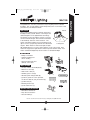
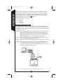
MAC100_IS_325-1586.qxp
10/17/06
2:50 PM
Page 1
ENGLISH
Instruction Manual
Instrucciones
Directives
ESPAÑOL
MAC100
CH4
CH3
CH2
CH1
FRANÇAIS
SEL
MAC100_IS_325-1586.qxp
10/17/06
2:50 PM
Page 2
Congratulations! You have purchased a Cooper Lighting motion activated
floodlight. This security lighting system will provide years of convenience and
protection for your family and home.
How it works
70 feet
Your Cooper Lighting motion activated camera and
floodlight security system delivers color images and
audio through the use of digital wireless technology.
The wireless receiver (included) connects to a television and real-time images and sound are transmitted
to the auxilliary channels on the television. The
motion activated floodlight senses heat images from
110 degrees
objects such as people, large animals and automotive
engines. When motion is detected at night, the light
will automatically turn on so the camera images can be seen clearly. Once
motion has stopped, the light will turn off after a preselected time delay. Your
motion activated floodlight may also be used as a standard floodlight.
What you need
• Phillips screwdriver
• Outdoor weatherproof
silicon caulking
• Television with audio and
auxiliary connections
SEL
CH4
CH3
CH2
CH1
B
What’s included
A
• Security camera and floodlight (A)
• Wireless receiver (B)
• Audio / video cable (C)
D
• Auxilliary power cord (D)
C
• 100 watt quartz halogen bulb (E)
E
• (2) #6-32: (2) #8-32 screws provided,
use the size that fits your junction box (F)
F
• (3) Wire nuts (G)
G
• Mounting bracket (H)
• (2) Decorative nuts (J)
J
Important Safety Instructions
• Read these instructions.
H
• Keep these instructions.
• Heed all warnings.
Call for customer service and/or missing or damaged parts (800-334-6871)
2
ENGLISH
MAC100
MAC100_IS_325-1586.qxp
10/17/06
2:50 PM
Page 3
• Follow all instructions.
ENGLISH
• Do not use this apparatus near water.
• Clean only with a dry cloth.
• Do not block any ventilation openings. Install in accordance with the
manufacturer’s instructions.
• Do not install near any heat sources such as radiators, heat registers,
stoves or other apparatus (including amplifiers) that produce heat.
• Do not defeat the safety purpose of the polarized or grounding-type
plug. A polarized plug has two blades with one wider than the other.
A grounding-type plug has two blades and a third grounding prong.
The wide blade or the third prong are provided for your safety. If the
provided plug does not fit into your outlet, consult an electrician for
replacement of the obsolete outlet.
• Protect the power cord from being walked on or pinched particularly at
plugs, convenience receptacles and at the point they exit from the apparatus.
• Only use attachments / accessories specified by the manufacturer.
• Unplug this apparatus during lightning storms or when unused for
long periods of time.
• Refer all servicing to qualified service personnel. Servicing is required
when the apparatus has been damaged in any way, such as power-supply
cord or plug is damaged, liquid has been spilled or objects have fallen into
the apparatus, the apparatus has been exposed to rain or moisture, does
not operate normally or has been dropped.
What to know
• For outdoor use only.
• ETL and CETL Listed for wet locations.
• Fixture must be connected to a 120 Volt, 60 Hz power source. Any other
connection voids warranty.
• Fixture should be mounted to a grounded junction box marked for use
in wet locations.
• Do not allow sensor head to touch light housing – maintain at least 1/2˝
space between fixture and sensor.
• Keep away from flammable objects. Do not mount body
of fixture within 1˝ of any combustible material.
• The bulb and fixture get extremely hot during use.
• Always replace bulb with the same or lower wattage
than the bulb included. Installing a higher wattage bulb
could create a fire hazard and shorten the life of the bulb. Use of a higher
wattage bulb will void the warranty.
• Never touch the bulb with your bare hands. Handle the bulb with gloves or
a soft cloth. Oil from your skin can cause premature bulb failure.
Call for customer service and/or missing or damaged parts (800-334-6871)
3
MAC100_IS_325-1586.qxp
10/17/06
2:50 PM
Page 4
• For maximum bulb life, position fixture so the quartz halogen bulb remains
within 4 degrees of horizontal.
• Fixture should be installed by persons with experience in household wiring
or by a qualified electrician. The electrical system and the method of
electrically connecting the fixture to it, must be in accordance with the
National Electrical Code and local building codes.
• For proper operation and protection against damage; the motion sensor head
adjustment knobs must be facing the ground.
• Disassembly of your fixture will void the warranty.
• Your fixture is pre-wired and pre-assembled for easy installation.
• This device complies with Part 15 of the FCC Rules. Operation is subject
to the following two conditions: (1) This device may not cause harmful
interference, and (2) this device must accept any interference received,
including interference that may cause undesired operation. Under Part
15 of the FCC Rules, any changes or modifications to the motion detector
described in this instruction sheet that are not expressly approved by
Cooper Lighting could void the user’s authority to operate the equipment.
Note: This equipment has been tested and found to comply with the limits for
a Class B digital device, pursuant to part 15 of the FCC Rules. These limits are
designed to provide reasonable protection against harmful interference in a residential installation. This equipment generates, uses and can radiate radio frequency energy and if not installed and used in accordance with the instructions,
may cause harmful interference to radio communications. However, there is no
guarantee that interference will not occur in a particular installation. If this equipment does cause harmful interference to radio or television reception, which can
be determined by turning the equipment off and on, the user is encouraged to try
to correct the interference by one or more of the following measures:
• Reorient or relocate the receiving antenna.
• Increase the separation between the equipment and receiver.
• Connect the equipment into an outlet on a circuit different from that to which
the receiver is connected.
• Consult the dealer or an experienced radio/TV technician for help.
WARNING: FCC Regulations state that any unauthorized changes or modifications to this equipment not expressly approved by the manufacturer could
void the user’s authorization to operate this equipment.
Cooper Lighting and ETL have not tested the performance or reliability of the
security or signaling aspects of this product. ETL has only tested for fire, shock
and/or casualty hazards as outlined in UL’s Standard(s) for Safety UL 6500. ETL
Certification does not cover the performance or reliability of the security or signaling aspects of this product. ETL makes no representations, warranties or
certifications whatsoever regarding the performance or reliability of any
security or signaling related functions of this product.
Call for customer service and/or missing or damaged parts (800-334-6871)
4
ENGLISH
• If lens is replaced, use only tempered safety glass of equal thickness.
MAC100_IS_325-1586.qxp
10/17/06
2:50 PM
Page 5
For best results
ENGLISH
• Install your fixture 8-12 feet above the ground.
• Locate fixture so motion moves across
detection zone (L)
• Locate fixture away from heat producing sources to
prevent false triggering. Also be very careful not to
include objects such as windows, white walls and
water in the detection zone whenever possible.
L
• Locate fixture away from moving objects such
as trees and street traffic.
• Do not install more than one motion activated
floodlight on one wall switch.
Installing the bulb
Step 1:
Remove screw from bottom of lens frame.
Step 2:
Using gloves or a soft cloth, gently insert
bulb by pressing one end into the spring
loaded socket on end indicated by reflector
marking and repeat with the opposite end.
Bulb should fit securely into the contacts (M).
Step 3:
M
Secure lens frame onto the fixture with screw.
Putting up your fixture
Note: Fixture may be vertically installed
in either the wall mount (N) or eave
mount position as shown (O).
Step 1:
Turn off the power at the main
fuse/breaker box.
Step 2:
Match up screws on the floodlight
mounting bracket with the junction
box screw holes. Make sure that
screws protruding from mounting
plate are in a horizontal position.
O
N
Wall mount
Eave mount
Your fixture mounts
to the following recessed
standard junction boxes:
Step 3:
Connect black wire to house
black wire and connect white
wire to house white wire using
wire nuts provided.
Step 4:
Attach yellow/green wire from
the fixture to ground wire coming
from your house using wire nut provided (G). If no ground wire
is available, attach fixture ground wire to the junction box.
Step 5:
Attach fixture to the mounting bracket (H) with the decorative nuts
(J) provided.
Round
Rectangular (horizontal)
Call for customer service and/or missing or damaged parts (800-334-6871)
5
Octagonal
MAC100_IS_325-1586.qxp
10/17/06
2:50 PM
Page 6
Apply silicone caulking around the edges of
coverplate and in any open screw holes for a
watertight seal.
Step 7:
Adjust the antenna upright and vertical to
the ground (P).
Step 8:
Turn power on at main fuse/breaker box.
ENGLISH
Step 6:
How to operate your fixture
Step 1:
Step 2:
Step 3:
Make sure motion sensor and wireless receiver
are set to the same house code (fixtures will
come from factory pre-set to the same code).
You may reset the house code by moving the
slide switch on the bottom of the fixture into
one of the four positions (P). The wireless
receiver (B) should be on the same
channel. To change the channel on
the wireless receiver, press the SEL
button on the front of the receiver and
the LED light will indicate the channel
in operation (Q).
Move Lux Control knob on bottom of
sensor to “T” (test) position and the
time adjustment slide switch to the
5˝ (seconds) position (R).
Turn on the power to fixture. Turn on
the wall switch. Allow fixture to warm
up approximately 90 seconds before
testing. (Lights may not come on
during warm-up period).
P
SEL
CH4
CH3
CH2
CH1
Q
Time Adjustment
R
Lux Control Knob
Step 4:
Aim sensor head in desired position.
Walk across the detection zone at the
farthest distance you wish your detector
to detect motion. Make sure sensor head
is positioned with control switches facing
towards the ground.
Step 5:
Adjust motion sensor up, down, left or right until you get desired
results. Light will turn off 5 seconds after motion stops in the “T”
position. Wait 4 seconds after the floodlight turns off before moving
again to test the sensor.
Note: For maximum range performance, allow fixture to operate in any mode
(with power to the unit) for at least 48 hours.
Step 6:
Move slide switch from 5˝ to either 10, 5, or 1 minute mode and light
will remain on for pre-selected time after the last motion is detected
at night (R). Turn LUX control knob to
position.
Call for customer service and/or missing or damaged parts (800-334-6871)
6
10/17/06
2:50 PM
Page 7
Note: The LUX Adjustment Knob determines when the floodlight will begin
operating. Turn the motion sensor LUX control knob clockwise to the moon
(dusk) position. In this setting the floodlight will remain in the OFF position
during daylight hours. If you would like the floodlight to turn on early (before
dusk), move the knob closer to the
position.
Note: Time adjustment settings:
5˝
1
5
10
=
=
=
=
5 seconds
1 minute
5 minutes
10 minutes
How to operate Wireless Receiver
The 2.4 GHz wireless receiver is designed to connect to your television to serve
as a medium to receive the radio frequency signal from the Motion Activated
floodlight and camera. There are four selectable channels that can be manually
operated if needed.
Step 1:
Connect audio/visual cable (C) to the television and to the receiver (B).
Plug the yellow (video), white (audio) and red (audio) connnectors
into the corresponding connectors on the television and receiver (S).
Wireless receiver can be connected to TV directly, or to VCR, VCD
R/W or DVD R/W to receive RF signal from security camera.
Step 2:
Connect the auxillary power cord (D) to the DC Jack on the receiver
and to a standard 120 Volt power outlet (T).
Step 3:
Slide the power switch to the ON position on the wireless receiver (U).
Step 4:
Turn on the TV to the appropriate auxillary channel (some TV’s have
more than one auxillary channnel). The real-time images can be
viewed right from the TV, the channel LED will light up on the receiver
box when a particular channel is in use.
AUDIO (White)
Antenna
AUDIO (Red)
S
AUDIO (White)
AUDIO (Red)
Adapter
VIDEO (Yellow)
Auxillary Power Cord
TV
VIDEO (Yellow)
ENGLISH
MAC100_IS_325-1586.qxp
T
DC Jack
Power
ON/OFF
U
WIRELESS
RECEIVER
Call for customer service and/or missing or damaged parts (800-334-6871)
7
MAC100_IS_325-1586.qxp
Step 5:
10/17/06
2:50 PM
Page 8
How to select your desired feature
Desired
Operation:
Set Time Adjust
Switch To:
Wall ON/OFF
Switch Setting
LUX Control
Knob Setting
Lights should turn on
with motion only at
night and should turn
off after 1, 5 or 10
minutes.
AUTO 1, AUTO 5
or
AUTO 10
Keep the power to
the fixture on.
Auto setting
between
Lights should stay on
from dusk to dawn
and then reset to the
auto setting next
dawn.
AUTO 1, AUTO 5
or
AUTO 10
Turn the power “OFF”
then back “ON” twice
within 4 sec.
Time between first
and second operation
must be between
.5 - 2 seconds.
Auto setting
between
Lights should turn on
with motion both day
and night. Light
should turn off after 5
seconds.
TEST
5˝
Keep the power to the
fixture on.
Test setting
“T”
Reset fixture into the
auto setting (from
any setting).
AUTO 1, AUTO 5
or
AUTO 10
Turn the power
“OFF” for at least 90
seconds, then back
“ON”.
Auto setting
between
Call for customer service and/or missing or damaged parts (800-334-6871)
8
ENGLISH
If more than one security camera floodlight is used, different house
codes must be selected on each unit and can be viewed on the same
TV at different times by selecting the appropriate house code on the
wireless receiver.
MAC100_IS_325-1586.qxp
10/17/06
2:50 PM
Page 9
ENGLISH
What to do if…
OUTDOOR LIGHT
DOES NOT COME
ON WITH MOTION
AT NIGHT
Is there power to the fixture?
• Check to see that the circuit breaker has not been tripped.
• Be sure the wall switch is in the “ON” position.
• Be sure the bulb is not burned out or broken.
Is the surrounding ambient light too bright? (If so, the unit may
think it is daytime).
• Re-aim the head.
• Relocate or reposition the unit away from the light.
TURN OFF POWER BEFORE CONTINUING.
Is the wiring to the fixture loose?
• Check wiring, and reconnect if necessary using wire nuts
provided.
OUTDOOR LIGHT
COMES ON FOR NO
APPARENT REASON
AT NIGHT
Is there motion in the detection zone?
• Make sure the sensor is not picking up moving objects
such as trees, traffic, etc.
TEST FOR YOURSELF.
• Cover the sensor lens with cardboard to prevent sensor
from detecting motion. If the light stays off, something in
the detection zone is triggering the sensor.
• Repostion the sensor.
*If the light stays on with the sensor lens covered, contact
customer service.
LIGHT STAYS ON AT
NIGHT AND DOES NOT
TURN OFF
Is there motion in the detection zone?
• Make sure the sensor is not picking up moving objects
such as trees, traffic, etc.
• Reposition the sensor.
If there is no motion, then the unit may be in the override mode.
• Turn the light switch to the “OFF” position for 90 seconds,
and then turn back to the “ON” postion. This will send the
unit back into the AUTO mode.
*If the light stays on with the sensor lens covered, contact
customer service.
LIGHT CONTINUOUSLY
BLINKS ON AND OFF AT
NIGHT
The light given from the unit’s own lamp is affecting the
motion sensor.
• Re-aim the lamp.
• Reposition motion sensor.
LIGHT IS ON DURING
THE DAY
Are the controls on the bottom of the motion sensor in the
test mode?
• Adjust the control to the AUTO 1, 5 or 10 postion.
Is the motion detector shadowed?
• Reposition motion sensor.
CANNOT ACTIVATE
DUSK TO DAWN MODE
AT NIGHT (OVERRIDE)
Is the surrounding external ambient light too bright? (If so, the
unit may think it is daytime).
• Re-aim the head.
• Relocate or reposition the unit away from the light.
Are you allowing adequate time to enter the dusk to dawn
mode?
• Turn the light switch to the OFF and ON position twice
within 4 seconds. The interval between first and second
operation must be within 0.5 to 2 seconds.
Is there more than one fixture on an indoor wall switch?
• If so, put them on separate switches.
Call for customer service and/or missing or damaged parts (800-334-6871)
9
MAC100_IS_325-1586.qxp
10/17/06
2:50 PM
Page 10
Two Year Limited Warranty
Customer First Center
1121 Highway 74 South, Peachtree City, GA 30269
www.cooperlighting.com
Patent Pending
© 2006 Cooper Lighting
Reproductions of this document without prior written approval of Cooper Lighting are strictly prohibited.
Call for customer service and/or missing or damaged parts (800-334-6871)
Printed in China
10
ENGLISH
Cooper Lighting (“the Company”) warrants this product (“the product”) against
defects in material or workmanship for a period of two years from date of original purchase, and agrees to repair or, at the Company’s option, replace a defective product without charge for either replacement parts or labor during such
time. This does not include labor to remove or install fixtures.
This warranty is extended only to the original purchaser of the product. A purchasers receipt or other proof of date of original purchase acceptable to the
Company is required before warranty performance shall be rendered.
This warranty only covers product failure due to defects in materials or workmanship which occurs in normal use. It does not cover the bulb or failure of the
product caused by accident, misuse, abuse, lack of reasonable care, alteration,
or faulty installation, subjecting the product to any but the specified electrical
service or any other failure not resulting from defects in materials or workmanship. Damage to the product caused by separately purchased, non-Company
brand replacement bulbs and corrosion or discoloration of brass components are
not covered by this warranty.
There are no express warranties except as described above.
THE COMPANY SHALL NOT BE LIABLE FOR INCIDENTAL, SPECIAL OR
CONSEQUENTIAL DAMAGES RESULTING FROM THE USE OF THE PRODUCT OR ARISING OUT OF ANY BREACH OF THIS WARRANTY. ALL IMPLIED
WARRANTIES, IF ANY, INCLUDING IMPLIED WARRANTIES OF MERCHANTABILITY AND FITNESS FOR A PARTICULAR PURPOSE, ARE LIMITED
IN DURATION TO THE DURATION OF THIS EXPRESS WARRANTY. Some
states do not allow the exclusion or limitation of incidental or consequential damages, or limitations on how long an implied warranty lasts, so the above exclusions or limitations may not apply to you.
No other warranty, written or verbal, is authorized by the Company. This warranty gives you specific legal rights, and you may also have other rights which
vary from state to state.
To obtain warranty service, please write to Cooper Lighting, 1121 Highway 74
South, Peachtree City, GA 30269. Enclose product model number and problems you are experiencing, along with your address and telephone number. You
will then be contacted with a solution, or a Return Goods Authorization number
and full instructions for returning the product. All returned products must be
accompanied by a Return Goods Authorization Number issued by the Company
and must be returned freight prepaid. Any product received without a Return
Goods Authorization Number from the Company will be refused.
Cooper Lighting is not responsible for merchandise damaged in transit.
Repaired or replaced products shall be subject to the terms of this warranty and
are inspected when packed. Evident or concealed damage that is made in transit should be reported at once to the carrier making the delivery and a claim
filed with them.