1
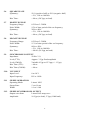
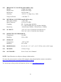
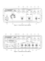
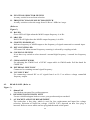
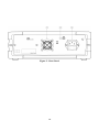
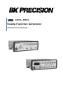
Model 4001A, 4003A Sweep Function Generator INSTRUCTION MANUAL Table of Contents Section 1 SAFETY GUIDELINES ............................................................................... 3 COMPLIANCE STATEMENTS.................................................................. 4 Section 2 INTRODUCTION ........................................................................................ 5 Section 3 TECHNICAL SPECIFICATIONS ............................................................... 6 Section 4 CONTROLS & INDICATORS .................................................................... 9 Section 5 OPERATING INSTRUCTIONS ................................................................ 13 5.1 Function Generator Output ........................................................... 13 5.2 Sweep Generator Output .............................................................. 13 5.3 Frequency Counter ....................................................................... 13 5.4 Voltage Controlled Frequency Operation..................................... 14 5.5 Function Generator Applications Guidebook ............................... 14 Section 6 MAINTENANCE ....................................................................................... 15 6.1 Preventive Maintenance ............................................................... 15 6.2 Service Information ...................................................................... 15 6.3 Fuse Replacement ......................................................................... 15 6.4 Instrument Repair Service ............................................................ 15 Section 7 CUSTOMER SUPPORT ............................................................................ 16 Section 8 SERVICE INFORMATION ....................................................................... 17 2 Section 1 Safety Guidelines WARNING Normal use of test equipment exposes you to a certain amount of danger from electrical shock because testing must sometimes be performed where exposed voltage is present. An electrical shock causing 10 milliamps of current to pass through the heart will stop most human heartbeats. A voltage as low as 35 volts DC or AC (RMS) should be considered dangerous and hazardous since it can produce a lethal current under certain conditions. Higher voltages pose an even greater threat because such voltage can more easily produce a lethal current. Your normal work habits should include all accepted practices to prevent contact with exposed high voltage and to steer current away from your heart in case of accidental contact with high voltage. You will significantly reduce the risk factor if you know and observe the following safety precautions. 1. Don’t expose high voltage needlessly. Remove housings and covers only when necessary. Turn off equipment while making test connections in high voltage circuits. Discharge high voltage capacitors after removing power. 2. If possible, familiarize yourself with the equipment being tested and the location of its high voltage points. However, remember that high voltage may appear at unexpected points in defective equipment. 3. Use an insulated floor material or a large, insulated floor to stand on and an insulated work surface on which to place equipment and make certain such surfaces are not damp or wet. 4. Use the time proven “one hand in the pocket” technique while handling an instrument probe. Be particularly careful to avoid contacting a nearby metal object that could provide a good ground return path. 5. When testing AC-powered equipment, remember that AC line voltage is usually present on some power input circuits such as the on-off switch, fuses, power transformer etc. any time the equipment is connected to an AC outlet, even if the equipment is turned off. 6. Some equipment with a two-wire AC power cord, including some with polarized power plugs, is the “hot chassis” type. A plastic wooden cabinet insulates the chassis to protect the customer. When the cabinet is removed for servicing, a serious shock hazard exists if the chassis is touched. Not only does this present a dangerous shock hazard, but damage to test equipment. Always connect an isolation transformer between the AC outlet and the equipment under test. The B&K Precision Model TR-110 or 1604 Isolation Transformer or Model 1653 or 1655 AC Power Supply is suitable for most applications. To be on the safe side, treat all two-wire AC equipment as “hot chassis” unless you are sure it is isolated chassis or an earth ground chassis. 7. On test instruments or any equipment with a 3-wire AC power plug, use only a 3-wire outlet. This is a safety feature to keep the housing or other exposed elements at earth ground. 8. B&K Precision products are not authorized for use in any application involving direct contact between our product and the human body or for use as a critical component in a life support device or system. Here “direct contact” refers to any connection from or to our equipment via any cabling or switching means. A “critical component” is any component of a life support device or system whose failure to perform can be reasonably expected to cause failure of that device or system or to affect its safety or effectiveness. Never work all alone. Someone should be nearby to render aid if necessary. Training in CPR (cardiopulmonary resuscitation) first aid is highly recommended. 3 Compliance Statements Disposal of Old Electrical & Electronic Equipment (Applicable in the European Union and other European countries with separate collection systems) This product is subject to Directive 2002/96/EC of the European Parliament and the Council of the European Union on waste electrical and electronic equipment (WEEE), and in jurisdictions adopting that Directive, is marked as being put on the market after August 13, 2005, and should not be disposed of as unsorted municipal waste. Please utilize your local WEEE collection facilities in the disposition of this product and otherwise observe all applicable requirements. 4 Section 2 Introduction Models 4001A and 4003A are 4 MHz sweep function generators. Model 4003A has an added feature of a 20 MHz digital counter. The function generator generates sinusoidal, triangular, ramp, square, and pulse waveforms. The type of function is selectable through a rotary switch. The frequency is settable from 0.5 Hz to 4 MHz of the function with range selector switch and the frequency control knob for variable adjustments with multiplication factor of 0.04 to 4.0 of the selected frequency range. The signal amplitude can be adjusted from 0.2 V to 20 Vpp with no load conditions and 0.1 V to 10 Vpp with a 50 ohm load termination. The MAIN output has the provision of SYNC output signal (TTL level) when selected. The sweep generator offers linear or log sweep with variable sweep rate and adjustable sweep width. (model 4003A only) Auto ranging, 5-digit frequency counter is provided with range from 0.2 Hz to 20 MHz and resolution of 0.01 Hz. The counter is utilized for external as well as internal functions. (model 4003A only) In addition to the features above, an external voltage signal can be used to control the frequency of the function. With AC input signal, FM output can be generated. 5 Section 3 Technical Specifications 3.1 FREQUENCY CHARACTERISTICS Waveforms: Sine, Square, Triangle, Ramp, ± Pulse Range: 0.5 Hz to 4 MHz in 6 ranges Tuning Range: Variable multiplication factor of 0.04 to 4.0 of selected range Resolution: 0.001 Hz (model 4003A only) Operating Modes: Normal, Sweep, VCF Frequency Stability: Output will change less than 0.1 % for 15 minutes after switching ON and it will change less than 0.2 % for 24 Hours after switching ON 3.2 OUTPUT CHARACTERISTICS Impedance: 50 Ω ± 2 %. Level: Variable control From ≤ 0.2 Vpp (no load, Amplitude knob in pull position) ≤ 0.1 Vpp (50Ω load, Amplitude knob in pull position) To ≥ 20 Vpp (no load, Amplitude knob in push position) ≥ 10 Vpp (50Ω load, Amplitude knob in push position) Attenuation: -20 dB ±2% DC Offset: Variable: ±10 V open circuit, ± 5 V into 50 Ω 3.3 SINE WAVE Distortion: Harmonic Ratio: Frequency Response: 3.4 TRIANGULAR WAVE Symmetry: 50 % (positive half) to 50 % (negative half) < 2%, 1 Hz to 100 kHz 3.5 RAMP WAVE Frequency Range: Symmetry: Rising Wave Linearity: < 2% (1 Hz – 100 kHz) < 30 dB, 100 kHz to 4 MHz < 0.5 dB to 100 kHz < 1.5 dB, 100 kHz to 4 MHz 0.5 Hz to 3.5 MHz 80% (rise wave) to 20% (fall wave) < 5%, 1 Hz to 100 kHz < 2%, 1 Hz to 100 kHz 6 3.6 SQUARE WAVE Symmetry: Rise Time: 3.7 POSITIVE PULSE Frequency Range: Pulse Width: Symmetry: Rise Time: 3.8 NEGATIVE PULSE Frequency Range: Pulse Width: Symmetry: Rise Time: 50 % (positive half) to 50 % (negative half) < 2%, 1 Hz to 100 kHz < 90 ns, (20 Vpp, no load) 0.5 Hz to 3.5 MHz 15% of time period of the set frequency 20% to 80%, < 5%, 1 Hz to 100 kHz < 90 ns, (20 Vpp, no load) 0.5 Hz to 3.5 MHz 15 % of time period of the set frequency 80% to 20%, < 5%, 1 Hz to 100 kHz < 90 nS, (20 Vpp, no load) 3.9 SYNCHRONOUS OUTPUT Impedance: 50 Ω ± 2 % Level (TTL): Approx. 3 Vpp fixed amplitude Level (CMOS): Variable 4 Vpp to 15 Vpp (+/- 1 Vpp) Rise Time (TTL): < 60 ns Rise Time (CMOS): < 90 ns 3.10 VCF INPUT Input Level: Input Frequency: 0 to 10 V DC to 1 kHz SWEEP OPERATION Operating Mode: Sweep Rate: Width: Linear/ LOG 5 s to 10 ms 1:1 to 1:100 3.11 3.12 SWEEP SYNCHRONOUS OUTPUT Output waveform: Linear/LOG ramp wave Amplitude: 10 Vpp (no load), 5 Vpp (1 kΩ load) 7 3.13 FREQUENCY COUNTER (model 4003A only) Display: 5-digit, auto range Display Unit: Hz/kHz auto range Resolution: 0.01 Hz (max.) Accuracy: < 0.02 % ± 1 digit, for ≥ 1 kHz Temp coefficient: < 10 PPM / °C 3.14 EXTERNAL COUNTER (model 4003A only) Max. Input Voltage: < 150 Vrms Input Frequency: 0.2 Hz to 20 MHz Coupling: HF - for more than 100 kHz LF - with 100 kHz filter for less than 100 kHz Sensitivity: <100 mVrms (1 MHz), <200 mVrms (>1 MHz) 3.15 AC INPUT: 3.16 OPERATING ENVIRONMENT Temperature: 0 to 40ºC Humidity: 10% to 80% 3.17 STORAGE Temperature: Humidity: - 20ºC to 70ºC 0% to 90% 3.18 DIMENSIONS: W x H x D – 11” x 3.6” x 11.9” (279.4 x 91.4 x 302.3 mm) 3.19 WEIGHT: 5.5 lbs (2.5 kg.) 3.20 ACCESSORY: Power Cord, User’s Manual 115 V AC ±10 %, 50/60 Hz, fuse 600 mA or 230 V AC ±10 %, 50/60 Hz, fuse 300 mA NOTE: Specifications are subject to change without notice. To ensure the most current version of this manual, please download the current version here: http://www.bkprecision.com/search/manual/4001A_4003A For current up-to-date product information, please visit www.bkprecision.com 8 Section 4 Controls & Indicators 4.1 FRONT PANEL (Refer to Figure 1 & Figure 2) 1. POWER SWITCH Pushing the switch “ON” will light the LED of the 5 digit display to indicate power ON. 2. FREQUENCY CONTROL KNOB Used to adjust the required frequency for selected range with the multiplication factor of 0.04 to 4.0. 3. SYNC OUTPUT The TTL level square signal output synchronous with frequency of MAIN output. 4. SWEEP OUTPUT Sweep signal is available regardless of position of SWEEP ON switch (turned on and off by SWEEP RATE knob). 5. MAIN OUTPUT Function output signal provides normal mode or sweep mode output depending on mode selected. The maximum output impedance is 50 Ω. 6. AMPLITUDE KNOB The amplitude of the signal can be adjusted from 0.2 Vpp to 20 Vpp at no load. Pull the knob to attenuate the signal 10 times. 7. DC OFFSET This knob can apply a DC offset to the MAIN output signal. Turn the knob clockwise for positive offset and counterclockwise for negative offset. 8. SWEEP RATE This knob is used to adjust the sweep rate from 5 seconds to 10 milliseconds. Also if this knob is pulled, then sweep mode operation will be ON. 9. SWEEP WIDTH This knob is used to adjust the sweep width. When the knob is in “Push” condition, a linear sweep output will be available. When knob is in “Pull” condition, a log sweep output will be available. 9 Figure 1 – Front Panel Controls (4001A) Figure 2 - Front Panel Controls (4003A) 10 10. FUNCTION SELECTOR SWITCH A rotary switch for waveform selection. 11. FREQUENCY RANGE SELECTOR SWITCH A rotary switch to select the range from 10 Hz to 1 MHz in 6 steps. (Refer to Figure 2) 12. Hz LED Green LED will light when the MAIN output frequency is in Hz. 13. kHz LED Red LED will light when the MAIN output frequency is in kHz. 14. 5-DIGIT LED DISPLAY Indicates frequency of MAIN output or the frequency of signal connected to external input. 15. EXT COUNTER LED LED turns ON when external frequency counting is selected by coupling switch. 16. COUPLING SWITCH It is a three-way switch to select internal / external high frequency / external low frequency mode. 17. CMOS ADJUST KNOB For adjusting the CMOS level of SYNC output while in CMOS mode. Pull the knob for CMOS ON. 18. EXTERNAL INPUT BNC Connector for counting external signal frequency. 19. VCF INPUT BNC For connecting external DC or AC signal from 0 to 10 V to achieve voltage controlled frequency output. 4.2 REAR PANEL (Refer to Figure 3) 1. 40mm FAN Provided on rear panel for cooling purposes. 2. KENSINGTON SECURITY SLOT For use with Kensington locks to secure your product and prevent theft. 3. AC SOCKET AND FUSE DEPARTMENT The socket has a fuse plug, which is used for fuse replacement and input line voltage selection. Selection of input line voltage (110/230 VAC) depends on how fuse plug is inserted. Refer to arrow marks on fuse plug and the mark on the panel. 11 Figure 3 - Rear Panel 12 Section 5 Operating Instructions Before applying power to unit, make sure that input voltage setting is correct and the ventilation holes are not blocked. Ensure that ventilation fan is working well. It is necessary to inspect the generated signal with an oscilloscope before connecting it to any electronic circuit. Hence use of oscilloscope is mentioned in the procedure. Turn on the instrument with POWER SWITCH provided on the front panel. The display shows the reading as per present settings. 5.1 FUNCTION GENERATOR OUTPUT 1. Select the type of waveform required by FUNCTION SELECTOR SWITCH. 2. Select the range of frequency by FREQUENCY RANGE SELECTOR SWITCH. 3. Connect MAIN output signal to Channel 1 of oscilloscope and SYNC output signal to Channel 2 of oscilloscope. Set the trigger source of oscilloscope at Channel 2. 4. Set the frequency of the signal by adjustment knob. The display shows the frequency reading of signal. 5. Adjust the amplitude of the signal by AMPLITUDE KNOB. Pull the knob if the signal is to be attenuated 10 times. 6. Set the DC offset of signal by DC OFFSET knob to required level (-10 V to +10 V). 7. Check the impedance of the load before connecting (50 W max.). 5.2 SWEEP GENERATOR OUTPUT 1. Connect MAIN output to Channel 1 of oscilloscope and SWEEP output to Channel 2. 2. Channel 2 displays linear sawtooth waveform. SWEEP output is available regardless of SWEEP ON switch. If SWEEP WIDTH knob is pulled, then log sweep will be available. 3. Adjust the sweep rate by SWEEP RATE knob (adjustable from 5 s to 10 ms). 4. Adjust the starting frequency as explained in 5.1. 5. Pull the SWEEP RATE knob to turn sweep mode ON. 6. Channel 1 will display sweep wave. 7. Adjust the sweep width using the SWEEP WIDTH knob (1:1 to 1:100). 5.3 FREQUENCY COUNTER (model 4003A only) 1. Check the COUPLING switch position. The HF position is used for frequencies more than 100 kHz. LF position is used for frequencies less than 100 kHz. 2. The EXT COUNTER LED will be ON when COUPLING switch is selected for counting mode. 3. Connect the signal to EXT COUNTER BNC. 13 4. Display will show the frequency and Hz / kHz LED’s will light depending on the frequency. 5.4 VOLTAGE CONTROLLED FREQUENCY OPERATION (model 4003A only) The 4003A can be operated as a voltage controlled generator by using an external control voltage applied to the VCF input. 1. Select the desired frequency range and waveform. 2. Set the starting frequency with the variable control. Apply a positive DC voltage to the VCF input to increase the frequency. A voltage from 0 to +10 V will cause the frequency to increase by a factor of 100. 5.5 FUNCTION GENERATOR APPLICATIONS GUIDEBOOK B&K Precision offers a “Guidebook to Function Generators”, which describes numerous applications for this instrument, including hook-up details. It also includes a glossary of function generator terminology and an explanation of function generator circuit operation. It may be downloaded free of charge on our website, www.bkprecision.com. 14 Section 6 Maintenance 6.1 6.2 PREVENTIVE MAINTENANCE Please follow the following preventive steps to ensure the proper operation of your instrument. Never place heavy objects on the instrument. Never place a hot soldering iron on or near the instrument. Never insert wires, pins, or other metal objects into ventilation fan. Never move or pull the instrument with power cord or output lead. More importantly, never move instrument when power cord or output lead is connected. Do not obstruct the ventilation holes in the rear panel as this will increase the internal temperature. Do not operate the instrument with the cover removed unless you are a qualified service technician. Clean and check the calibration of the instrument on a regular basis to keep the instrument looking nice and working well. Remove any dirt, dust, and grime whenever they become noticeable on the outside cover with a soft cloth, moistened with a mild cleaning solution. SERVICE INFORMATION Some of the common problems that may occur and the remedy to put back the instrument in a working condition as fast as possible are given below. When the unit is not turning on. Check if the power ON/OFF switch is turned ON. If not, then check the power cord. Please make sure that the power cord is properly connected to the unit. Please also check the main switch. Ensure that the AC supply at your site is the same as the one mentioned at the rear chassis of the unit. For further help call the service personnel. 6.3 FUSE REPLACEMENT If the fuse blows, the LED will not light and the instrument will not operate. Replace only with the correct value fuse. The fuse is located on the rear panel adjacent to the power cord receptacle. Remove the fuse holder assembly as follows: 1. Unplug the power cord from rear of the instrument. 2. Insert a small screwdriver in fuse holder slot (located between fuse holder and receptacle). When reinstalling fuse holder, be sure that the fuse is installed so that the correct line voltage is selected. 6.4 INSTRUMENT REPAIR SERVICE 15 Because of the specialized skills and test equipment required for instrument repair and calibration, many customers prefer to rely upon B&K PRECISION for this service. To use this service, even if the instrument is no longer under warranty, follow the instructions given in the WARRANTY SERVICE INSTRUCTIONS portion of this manual. There is a nominal charge for instruments out of warranty. Section 7 Customer Support B&K Precision offers courteous, professional technical support before and after the sale of their test instruments. The following services are typical of those available from our toll-free telephone number. Technical advice on the use of your instrument. Technical advice on special applications of your instrument. Technical advice on selecting the test instrument for a given task. Information on optional accessories for your instrument. Information on instrument repair and re-calibration services. Replacement parts ordering. Availability on service publications. Information on other B&K Precision instruments. Information on other B&K Precision Catalog. Call toll free 800-462-9832 Monday through Thursday 8:00 A.M. to 5:00 P.M. Friday 8:00 A.M. to 12:00 P.M. Pacific Standard Time (Pacific Daylight Time Summer) 16 Section 8 SERVICE INFORMATION Warranty Service: Please return the product in the original packaging with proof of purchase to the address below. Clearly state in writing the performance problem and return any leads, probes, connectors, and accessories that you are using with the device. Non-Warranty Service: Return the product in the original packaging to the address below. Clearly state in writing the performance problem and return any leads, probes, connectors, and accessories that you are using with the device. Customers not on open account must include payment in the form of a money order or credit card. For the most current repair charges please visit www.bkprecision.com and click on “service/repair”. Return all merchandise to B&K Precision Corp. with pre-paid shipping. The flat-rate repair charge for NonWarranty Service does not include return shipping. Return shipping to locations in North American is included for Warranty Service. For overnight shipments and non-North American shipping fees please contact B&K Precision Corp. B&K Precision Corp. 22820 Savi Ranch Parkway Yorba Linda, CA 92887 www.bkprecision.com 714-921-9095 Include with the returned instrument your complete return shipping address, contact name, phone number, and description of problem. LIMITED ONE-YEAR WARRANTY B&K Precision Corp. warrants to the original purchaser that its products and the component parts thereof, will be free from defects in workmanship and materials for a period of one year from date of purchase. B&K Precision Corp. will, without charge, repair or replace, at its option, defective product or component parts. Returned product must be accompanied by proof of the purchase date in the form of a sales receipt. To obtain warranty coverage in the U.S.A., this product must be registered by completing a warranty registration form on www.bkprecision.com within fifteen (15) days of purchase. Exclusions: This warranty does not apply in the event of misuse or abuse of the product or as a result of unauthorized alterations or repairs. The warranty is void if the serial number is altered, defaced or removed. B&K Precision Corp. shall not be liable for any consequential damages, including without limitation damages resulting from loss of use. Some states do not allow limitations of incidental or consequential damages. So the above limitation or exclusion may not apply to you. This warranty gives you specific rights and you may have other rights, which vary from state-to-state. B&K Precision Corp. 22820 Savi Ranch Parkway Yorba Linda, CA 92887 www.bkprecision.com 714-921-9095 17 22820 Savi Ranch Parkway Yorba Linda, CA 92887 www.bkprecision.com © 2014 B&K Precision Corp. Printed in China v4.14.2014 18