1
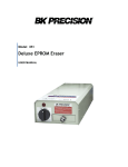
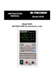
INSTRUCTION
MANUAL
MODEL 1686A
3 to 14 VOLT
DC POWER
SUPPLY
1
TEST INSTRUMENT SAFETY
WARNING
Normal use of test equipment exposes you to a certain amount of danger from electrical shock because testing must sometimes be
performed where exposed high voltage is present. An electrical shock causing 10 milliamps of current to pass through the hear t will
stop most human heartbeats. Voltage as low as 35 volts dc or ac rms should be considered dangerous and hazardous since it can
produce a lethal current under certain conditions. Higher voltage poses an even greater threat because such voltage can more easily
produce a lethal current. Your normal work habits should include all accepted practices that will prevent contact with exposed high
voltage, and that will steer current away from your heart in case of accidental contact with a high voltage. You will signifi cantly
reduce the risk factor if you know and observe the following safety precautions:
1. There is little danger of electrical shock from the dc output of this power supply. However, there are several other possible test
conditions using this power supply that can create a high voltage shock hazard:
a. If the equipment under test is the “hot chassis” type, a serious shock hazard exists unless the equipment is unplugged (just
turning off the equipment does not remove the hazard), or the precautions of step 8 are observed.
b. If the equipment under test is “powered up” (and that equipment uses high voltage in any of its circuits), the power supply
outputs may be floated to the potential at the point of connection. Remember that high voltage may appear at unexpected point s
in defective equipment. Do not float the power supply output to more than 100 volts peak with respect to chassis or earth
ground.
c. If the equipment under test is “off” (and that equipment uses high voltage in any of its circuits under normal operation),
discharge high-voltage capacitors before making connections or tests. Some circuits retain high voltage long after the
equipment is turned off.
2. Use only a polarized 3-wire ac outlet. This assures that the power supply chassis, case, and ground terminal are connected to a
good earth ground and reduces danger from electrical shock.
3. Don’t expose high voltage needlessly. Remove housings and covers only when necessary. Turn off equipment while making test
connections in high-voltage circuits. Discharge high-voltage capacitors after removing power.
(continued on inside rear cover)
2
Instruction Manual
for
MODEL 1686A
3 to 14 VOLT
DC POWER SUPPLY
22820 Savi Ranch Parkway
Yorba Linda, California 92887
3
TABLE OF CONTENTS
page
page
TEST INSTRUMENT SAFETY................................ inside front cover
MAINTENANCE............................................................................14
Fuse Replacement........................................................................14
Line Voltage Conversion.............................................................14
Adjustments.................................................................................14
Case Disassembly........................................................................14
Voltage and V Meter Adjustments..............................................15
Current and A Meter Adjustments...............................................15
Instrument Repair Service...........................................................16
INTRODUCTION.................................................................................5
SPECIFICATIONS................................................................................6
CONTROLS AND INDICATORS........................................................7
OPERATING INSTRUCTIONS...........................................................9
Safety Precautions..............................................................................9
Equipment Protection Precautions.....................................................9
Power Supply Hook-up and Operation..............................................9
Considerations..................................................................................10
Current Limiting..............................................................................11
Connecting Two Supplies in Series.................................................11
Connecting Two Supplies in Parallel...............................................11
4
SERVICE INFORMATION.......................................................... 17
LIMITED ONE-YEAR WARRANTY.......................................... 18
INTRODUCTION
The power supply utilizes thermostatically controlled fan
cooling for improved heat dissipation and reliability while
keeping bulk and weight to a minimum.
The B+K Precision Model 1686 is a high quality 3 to 14 Volt
DC Power Supply primarily designed for bench powering of
automotive and marine electronic equipment. The Model 1686
has a maximum output current proportional to the voltage setting,
the maximum current of 12 amps available from 13.8 to 14 volts
and is reduced to 2.5 amps at 3 volts. Two panel mounted meters
continuously monitor the output voltage and current.
Foldback current limiting protects the power supply from
accidental short circuits and overload conditions. The output is
isolated from chassis and earth ground, permitting full
flexibility of connections. When desired, the positive (+) or
negative (–) polarity outputs may be strapped to ground,
allowing use with negative-ground and positive-ground
automotive equipment.
The 12-amp output of the Model 1686 power supply allows
bench powering of most any car radio, sound system (including
most “high-power” car stereo receiver/amplifiers), tape systems,
PA systems, and low-to-medium power 2-way radios, such as CB
transceivers, VHF/UHF commercial equipment, marine, car
telephone, and 2-meter transceivers.
Advanced design, quality, and sturdy construction of the
Model 1686 assures continued reliability. To gain the most
effective use of this instrument, we recommend that you study
the entire manual before operating the power supply.
5
SPECIFICATIONS
OUTPUT VOLTAGE
3 to 14 VDC, ADJUSTABLE
Ammeter
Range
0 to 20A
OUTPUT CURRENT
PROPORTIONAL TO OUTPUT VOLTAGE;
3V
2.5A
5V
4.5A
9V
7.5A
12V
10.0A
13.8V
12.0A
14V
12.0A
LOAD REGULATION
(0 to Rated Current)
≤ 0.8%
LINE REGULATION
(108–132 VAC)
≤ 0.8%
RIPPLE & NOISE
≤ 10 mV rms
AC Input
115/230 VAC ±10%, 50/60Hz.
POWER CONSUMPTION
400 W
TEMPERATURE RANGE & HUMIDITY
Operation
0° to +40°C ≤ 85% R.H.
Storage
–15° to +70°C ≤ 75% R.H.
DIMENSIONS (H×W×D)
4.9 × 8.5 × 11.5’’ (124 × 216 × 292mm)
WEIGHT
12.1 lb. (5.45 kg)
PROTECTION
Current Limiting (Foldback), Reverse Polarity, Overvoltage, Short
Circuit.
METERING
Voltmeter
Range
0 to 20V
Accuracy
± 7% F.S.
ACCESSORIES SUPPLIED
Instruction Manual
Spare Fuse
Accuracy
± 7% F.S.
NOTE: Specifications and information are subject to change
without notice. Please visit www.bkprecision.com for the most
current product information.
6
CONTROLS AND INDICATORS
1. POWER Switch. Turns power supply on and off. Power on
indicated by pilot lamp above switch.
7. OUTPUT “+” Terminal (Red). Positive polarity output
terminal.
2. Power ON light. Lights when power is turned on.
8. OUTPUT “–” Terminal (Black). Negative polarity output terminal.
3. OVERLOAD Indicator. Lights when overload condition
exists.
9. TIE POINTS (2A MAX). Red terminals are +, Black terminals
are –. Load must not exceed 2 amperes.
4. VOLTAGE Control. Adjusts output voltage. Read value on V
Meter.
10. Line Cord.
11. Fuse.
5. A Meter. Indicates output current on 0 to 20 amp. scale.
12. Fan.
6. V Meter. Indicates output voltage on 0 to 20 volt scale.
7
CONTROLS AND INDICATORS
Figure 2. Rear Panel
Figure 1.
Front Panel Controls and Indicators, Model 1686A.
8
OPERATING INSTRUCTIONS
SAFETY PRECAUTIONS
EQUIPMENT PROTECTION PRECAUTIONS
WARNING
CAUTION
The following precautions must be observed to
help prevent electric shock.
The following precautions will help avoid
damage to the power supply.
1. Avoid using the power supply in ambient temperatures
above +40°C (104°F). Always allow sufficient air space
around the fan opening at the rear of the power supply and
the top and side vent openings for effective air flow to
prevent internal heat build-up. Typically, a two inch space
at the sides, as well as a six inch space at the top and rear
of the power supply is adequate. DO NOT block the fan
opening at the rear of the power supply or the vent on top
of the power supply. DO NOT place objects on top of the
power supply.
1. Use only a polarized 3-wire ac outlet. This assures that the
power supply chassis and case are connected to a good earth
gr o u n d a n d reduces danger from electrical shock.
2. There is little danger of electric shock from the power supply
output, which produces a maximum of 14.0 volts dc.
However, there may be great danger of electrical shock if the
power supply output is connected to an external high
voltage. Some equipment being powered may contain high
voltage and present a shock hazard. Observe caution. If the
power supply output is floated (referenced to a voltage rather
than earth ground) turn off the power supply and the
equipment under test when making connections. Never float
the power supply to a potential greater than 100 volts peak
with respect to earth ground.
2. Although the power supply is protected against overload
and short circuits, avoiding these conditions in regular use
results in maximum stability and reliability.
3. Make certain that hook-up is as intended before turning
power supply on. Incorrect polarity may damage the
equipment being powered.
3. Observe all TEST INSTRUMENT SAFETY precautions
listed in the front of this manual.
POWER SUPPLY HOOK-UP and OPERATION
1. Turn off the power supply and equipment being powered.
9
OPERATING INSTRUCTIONS
NOTE
3. The clip type TIE POINT terminals can be used to attach
equipment requiring a maximum of 2 amps. Be sure to
observe polarity when connecting equipment.
4. If more precision voltage readings are desired, connect a
high-accuracy multimeter, such as the 0.5% B+K
Precision Model 388A Digital Multimeter or equivalent
across a pair of (+) and (–) TIE POINT terminals.
Use solid copper hook-up wire with a
minimum diameter of 12 AWG. Using
smaller wire may result in overheating of
the hook-up leads, and increases the
source resistance “seen” by the load,
thereby derating the maximum current
and regulation capabilities of the power
supply. Tighten connections snugly to
assure low resistance.
2. Connect the red (+) OUTPUT terminal of the power supply to the
positive polarity input of the equipment being powered.
3. Connect the black (–) OUTPUT terminal of the power supply to
the negative polarity input of the equipment being powered.
4. Set the VOLTAGE control to its minimum (counter clockwise)
position.
5. Turn on the power supply.
6. Turn on the equipment being powered.
7. Adjust the VOLTAGE control to the desired voltage as read on
the V meter.
CONSIDERATIONS
1. Although vehicular electrical systems are typically referred to as
“12 volt systems”, the actual nominal operating voltage of such
systems is approximately 13.8 volts. Therefore, for purposes of
normal operation, adjust the power supply for 13.8 volts.
2. Maximum current is dependent upon output voltage as shown in
Fig. 3.
Figure 3. Typical Output Voltage and
Output Current Characteristics
10
OPERATING INSTRUCTIONS
CURRENT LIMITING
The voltage is controlled by both VOLTAGE controls and is
equal to the sum of the two V meter readings. Adjust voltage
so that each power supply provides about half the total voltage.
Overload (Foldback) current limiting gives protection against
excessive overload and short circuit output. When an overload
(foldback) condition exists, the unit drops out of voltage regulation and
the OVERLOAD indicator will be illuminated. The foldback
characteristic shown in the graph in Fig. 3 takes effect before the
primary fuse blows, dropping the output voltage and current in
proportion to the degree of overload. If the output is short-circuited
(maximum overload condition), the output current drops below its
rating at 3V. Monitoring the output voltage and current will detect any
such overload conditions.
CONNECTING TWO SUPPLIES IN PARALLEL
(Refer to Fig. 5)
The outputs of two Model 1686 power supplies may be
connected in parallel to double the current capacity to 24
amperes. The output voltage remains at 3-to-14 volts output.
See Fig. 5 for the connection scheme.
The voltage level of both VOLTAGE controls should be set
simultaneously to the same value. Fine adjust the VOLTAGE
controls for equal readings on the A meters. This will allow
each power supply to provide one-half of the total current.
Current will be equal to the sum of both A meters. Current
limiting resistors are not required since hook-up wire
resistance will provide sufficient isolation.
CONNECTING TWO SUPPLIES IN SERIES
(Refer to Fig. 4)
The outputs of two supplies may be connected in series to
provide a variable 6-to-28 volts output. The maximum output
current will remain at 12 amps. See Fig. 4 for the connection
scheme.
11
OPERATING INSTRUCTIONS
Figure 4. Connecting Two Power Supplies in Series for a 6-to-28 Volt Output.
12
OPERATING INSTRUCTIONS
Figure 5. Connecting Two Power Supplies in Parallel for 3-to-14 Volt Output at Double Amperage.
13
MAINTENANCE
WARNING
1. Make sure the power cord is unplugged.
2. Turn the unit over (bottom up) and reset the LINE
VOLTAGE SELECT switch for the desired line voltage,
115V or 230V.
The following instructions are for use by
qualified personnel only. To avoid electrical
shock, do not perform any servicing other
than contained in the operating instructions
unless you are qualified to do so.
3. A change in line voltage will also require a corresponding
change of fuse value. Install the correct fuse value as
listed in the FUSE REPLACEMENT section.
FUSE REPLACEMENT
ADJUSTMENTS
If the fuse blows, the power on LED indicator will not light
and the power supply will not operate. The fuse should not
normally open unless a problem has developed in the unit. Try to
determine and correct the cause of the blown fuse, then replace
only with a fuse of the correct rating. The fuse is located on the
rear panel (see Fig. 2).
LINE VOLTAGE
FUSE VALUE
115V
4A
This unit was accurately adjusted at the factory before
shipment. Readjustment is recommended only if repairs have
been made in a circuit affecting adjustment accuracy, or if you
have a reason to believe the unit is out of adjustment. However,
adjustments should be attempted only if a 3-1/2 digit
multimeter with an accuracy of ±0.5% dcV or better (B+K
Precision Model 388A or equivalent) and a 0 to 2 Ω, 250 Watt
adjustable resistive load is available.
230V
2A
LINE VOLTAGE CONVERSION
If readjustment is required, use the following procedure.
Locations of the electrical adjustments are shown in Fig. 6.
The primary winding of the power transformer is tapped to
permit operation from 115 or 230 VAC, 50/60 Hz line voltage.
Conversion from one line voltage to another is done by simply
changing the position of the LINE VOLTAGE SELECT switch
located on the bottom of the chassis. To convert to a different
line voltage, perform the following procedure:
CASE DISASSEMBLY
1. Turn the unit over, bottom up, and remove the three
screws that hold the front bezel to the chassis.
14
MAINTENANCE
2. Remove the ten screws that hold the case top to the chassis and
front bezel.
3. Pull the front bezel away from the chassis to access the
calibration adjustments.
VOLTAGE AND V METER ADJUSTMENTS
1. Connect the multimeter (set to 20 DCV Range) to measure the
dc voltage across the power supply (+) and (–) OUTPUT
terminals.
2. Turn on the power supply, and set the front panel VOLTAGE
control maximum (fully clockwise).
3. Adjust Trimmer VR3 for a reading of 14.50 ± 0.10 volts on the
multimeter.
4. Set the power supply front panel VOLTAGE control for a
reading of 14.00 ± 0.10 volts on the multimeter.
5. Adjust Trimmer VR4 so that the meter pointer on the V meter
lines up with the 14 volt mark.
6. Turn off unit power to proceed to the current adjustments.
CURRENT AND A METER ADJUSTMENTS
1. Connect the 0 to 2 ohm resistive load in series with the
multimeter (set to 20 DCA Range) to measure the dc output
current across the power supply (+) and (–) OUTPUT
terminals.
2. Turn on the power supply and adjust the resistive load for a
reading of 10.0 ± 0.1 amps on the multimeter.
Figure 6. Location of Calibration Adjustments, Rear View.
15
MAINTENANCE
3. Adjust Trimmer VR5 so that the meter pointer on the A
meter lines up with the 10 amp mark.
4. Remove the multimeter in series with the load, and reconnect
it in parallel with the load to measure voltage (set to 20 DCV
Range).
5. Adjust Trimmer VR2 fully counter clockwise, looking at the
front of the unit.
6. Re-adjust the power supply front panel VOLTAGE control
for a reading of 14.0 ± 0.5 volts on the multimeter if
necessary.
7. Adjust the resistive load for a reading of 15 amps on the
unit’s A meter scale.
8. Adjustable Trimmer VR2 clockwise unit the output voltage
read on the multimeter drops by 0.05 to 0.20 V.
16
INSTRUMENT REPAIR SERVICE
Because of the specialized skills and test equipment required
for instrument repair and calibration, many customers prefer to
rely upon B+K Precision for this service. We maintain a network
of B+K Precision authorized service agencies for this purpose.
To use this service, even if the instrument is no longer under
warranty, follow the instructions given in the SERVICE
INFORMATION section of this manual. There is a nominal
charge for instruments out of warranty.
Service Information
Warranty Service: Please return the product in the original packaging with proof of purchase to the address below. Clearly state in writing
the performance problem and return any leads, probes, connectors and accessories that you are using with the device.
Non-Warranty Service: Return the product in the original packaging to the address below. Clearly state in writing the performance problem
and return any leads, probes, connectors and accessories that you are using with the device. Customers not on open account must include
payment in the form of a money order or credit card. For the most current repair charges please visit www.bkprecision.com and click on
“service/repair”.
Return all merchandise to B&K Precision Corp. with pre-paid shipping. The flat-rate repair charge for Non-Warranty Service does not
include return shipping. Return shipping to locations in North American is included for Warranty Service. For overnight shipments and nonNorth American shipping fees please contact B&K Precision Corp.
B&K Precision Corp.
22820 Savi Ranch Parkway
Yorba Linda, CA 92887
www.bkprecision.com
714-921-9095
Include with the returned instrument your complete return shipping address, contact name, phone number and description of
problem.
17
Limited One-Year Warranty
B&K Precision Corp. warrants to the original purchaser that its products and the component parts thereof, will be free from defects in
workmanship and materials for a period of one year from date of purchase.
B&K Precision Corp. will, without charge, repair or replace, at its option, defective product or component parts. Returned product must be
accompanied by proof of the purchase date in the form of a sales receipt.
To help us better serve you, please complete the warranty registration for your new instrument via our website www.bkprecision.com
Exclusions: This warranty does not apply in the event of misuse or abuse of the product or as a result of unauthorized alterations or
repairs. The warranty is void if the serial number is altered, defaced or removed.
B&K Precision Corp. shall not be liable for any consequential damages, including without limitation damages resulting from loss of use.
Some states do not allow limitations of incidental or consequential damages. So the above limitation or exclusion may not apply to you.
This warranty gives you specific rights and you may have other rights, which vary from state-to-state.
B&K Precision Corp.
22820 Savi Ranch Parkway
Yorba Linda, CA 92887
www.bkprecision.com
714-921-9095
18
TEST INSTRUMENT SAFETY
(continued from inside front cover)
4. If possible, familiarize yourself with the equipment being tested and the location of its high voltage points. However, remember that high voltage may
appear at unexpected points in defective equipment.
5. Use an insulated floor material or a large, insulated floor mat to stand on, and an insulated work surface on which to place equipment; and make certain
such surfaces are not damp or wet.
6. Use the time-proven “one hand in the pocket” technique while handling an instrument probe. Be particularly careful to avoid contacting a nearby metal
object that could provide a good ground return path.
7. When testing ac powered equipment, remember that ac line voltage is usually present on some power input circuits such as the on-off switch, fuses,
power transformer, etc. any time the equipment is connected to an ac outlet, even if the equipment is turned off.
8. Some equipment with a two-wire ac power cord, including some with polarized power plugs, is the “hot chassis” type. This includes most recent
television receivers and audio equipment. A plastic or wooden cabinet insulates the chassis to protect the customer. When the cabinet is removed for
servicing, a serious shock hazard exists if the chassis is touched. Not only does this present a dangerous shock hazard, but damage to test instruments or
the equipment under test may result from connecting an earth ground lead of a test instrument to a “hot chassis”. To make measurements in “hot
chassis” equipment, always connect an isolation transformer between the ac outlet and the equipment under test. The B+K Precision Model TR-110 or
1604 Isolation Transformer, or Model 1653 or 1655 AC Power Supply is suitable for most applications. To be on the safe side, treat all two-wire ac
powered equipment as “hot chassis” unless you are sure it has an isolated chassis or an earth ground chassis.
9. B+K Precision products are not authorized for use in any application involving direct contact between our product and the human body, or for use as a
critical component in a life support device or system. Here, “direct contact” refers to any connection from or to our equipment via any cabling or
switching means. A “critical component” is any component of a life support device or system whose failure to perform can be reasonably expected to
cause failure of that device or system, or to affect its safety or effectiveness.
10. Never work alone. Someone should be nearby to render aid if necessary. Training in CPR (cardio-pulmonary resuscitation) first aid is highly
recommended.
19
B&K Precision Corporation
22820 Savi Ranch Parkway
Yorba Linda, California 92887
www.bkprecision.com
©2014 B&K Precision Corporation
481-370-9-001
Printed in China
V043014
20