1
Chapter 5
RUGGEDCOM ROS
Setup and Configuration
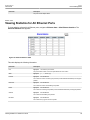
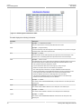
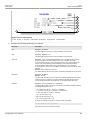
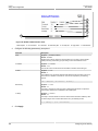
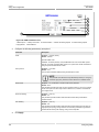
Parameter
User Guide
Description
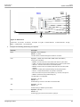
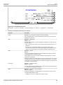
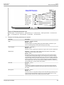
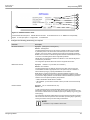
the ability to preferentially select specific ports to carry traffic over others. Leave this
field set to "auto" to use the standard RSTP port costs as negotiated (20,000 for 1Gbps,
200,000 for 100 Mbps links and 2,000,000 for 10 Mbps links).
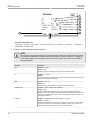
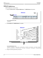
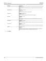
Edge Port
Synopsis: { False, True, Auto }
Default: Auto
Edge ports are ports that do not participate in the Spanning Tree, but still send
configuration messages. Edge ports transition directly to frame forwarding without
any listening and learning delays. The MAC tables of Edge ports do not need to be
flushed when topology changes occur in the STP network. Unlike an STP disabled port,
accidentally connecting an edge port to another port in the spanning tree will result in a
detectable loop. The "Edgeness" of the port will be switched off and the standard RSTP
rules will apply (until the next link outage).
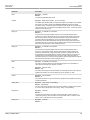
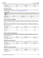
Point to Point
Synopsis: { False, True, Auto }
Default: Auto
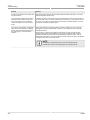
RSTP uses a peer-to-peer protocol that provides rapid transitioning on point-to-point
links. This protocol is automatically turned off in situations where multiple STP bridges
communicate over a shared (non point-to-point) LAN. The bridge will automatically take
point-to-point to be true when the link is found to be operating in full-duplex mode. The
point-to-point parameter allows this behavior or overrides it, forcing point-to-point to
be true or false. Force the parameter true when the port operates a point-to-point link
but cannot run the link in full-duplex mode. Force the parameter false when the port
operates the link in full-duplex mode, but is still not point-to-point (e.g. a full-duplex link
to an unmanaged bridge that concentrates two other STP bridges).
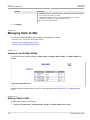
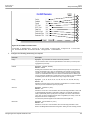
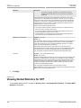
Restricted Role
Synopsis: { True or False }
Default: False
A boolean value set by management. If TRUE, causes the Port not to be selected as the
Root Port for the CIST or any MSTI, even if it has the best spanning tree priority vector.
Such a Port will be selected as an Alternate Port after the Root Port has been selected.
This parameter should be FALSE by default. If set, it can cause a lack of spanning tree
connectivity. It is set by a network administrator to prevent bridges that are external to
a core region of the network from influencing the spanning tree active topology. This
may be necessary, for example, if those bridges are not under the full control of the
administrator.
Restricted TCN
Synopsis: { True or False }
Default: False
A boolean value set by management. If TRUE, it causes the Port not to propagate
received topology change notifications and topology changes to other Ports. If set,
it can cause temporary loss of connectivity after changes in a spanning tree’s active
topology as a result of persistent, incorrectly learned, station location information. It
is set by a network administrator to prevent bridges that are external to a core region
of the network from causing address flushing in that region. This may be necessary,
for example, if those bridges are not under the full control of the administrator or if the
MAC_Operational status parameter for the attached LANs transitions frequently.
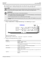
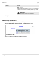
4.
Click Apply.
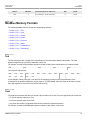
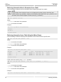
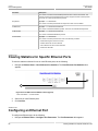
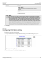
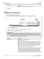
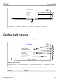
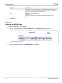
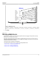
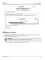
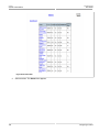
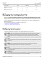
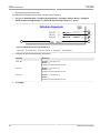
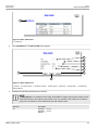
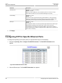
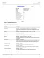
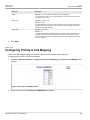
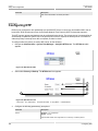
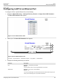
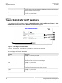
Section 5.3.5
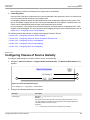
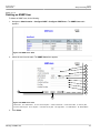
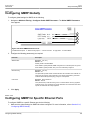
Configuring eRSTP
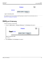
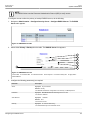
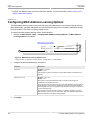
To configure eRSTP, do the following:
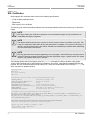
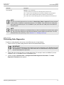
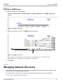
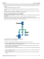
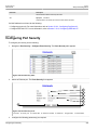
1.
146
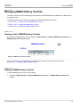
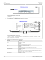
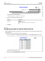
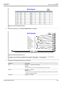
Navigate to Spanning Tree » Configure eRSTP Parameters. The eRSTP Parameters form appears.
Configuring eRSTP