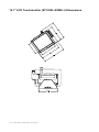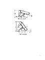
1
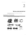
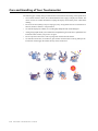
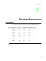
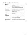
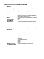
Elo Entuitive Touchmonitor
User Guide 1229L(WWW)
For 12.1" LCD Touchmonitors with Optional Magnetic Stripe Reader,
Finger Print Reader and Rear Facing Customer Display
Revision A
Elo Entuitive Touchmonitor
User Guide
12.1" LCD Touchmonitor with Optional Mag
Stripe Reader, Finger Print Reader and Rear
Facing Customer Display
ET1229L Series
Revision A
P/N E799279
Elo TouchSystems, Inc.
1-800-ELOTOUCH
www.elotouch.com
Copyright © 2003 Elo TouchSystems Inc. All Rights Reserved.
No part of this publication may be reproduced, transmitted, transcribed, stored in a retrieval system,
or translated into any language or computer language, in any form or by any means, including, but not
limited to, electronic, magnetic, optical, chemical, manual, or otherwise without prior written
permission of Elo TouchSystems.
Disclaimer
The information in this document is subject to change without notice. Elo TouchSystems makes no
representations or warranties with respect to the contents hereof, and specifically disclaims any
implied warranties of merchantability or fitness for a particular purpose. Elo TouchSystems reserves
the right to revise this publication and to make changes from time to time in the content hereof
without obligation of Elo TouchSystems to notify any person of such revisions or changes.
Trademark Acknowledgments
IntelliTouch, SecureTouch, AccuTouch, Entuitive, and MonitorMouse are trademarks of Elo
TouchSystems, Inc.
Other product names mentioned herein may be trademarks or registered trademarks of their
respective companies. Elo TouchSystems claims no interest in trademarks other than its own.
Table of Contents
Chapter 1
Introduction
Chapter 3
1
Product Description ................................................... 1
Detailed LCD Display Performance
Operation
31
About Touchmonitor Adjustments .............................. 31
Requirements ............................................................. 2
Controls and Adjustment ............................................ 33
OSD Lock/Unlock ...................................................... 33
Customer Display ...................................................... 3
Serial Version ............................................................. 3
Power Lock/Unlock .............................................. 33
Fingerprint Reader ..................................................... 3
OSD Menu Functions .......................................... 33
OSD Control Options ........................................... 34
Theory of Operation ................................................... 4
Sensor Specifications ................................................ 4
Contrast ......................................................... 34
Credit Card Reader .................................................... 4
Brightness ...................................................... 34
V-Position ....................................................... 34
Six Port USB Hub ...................................................... 5
External 12 VDC Power Supply ................................. 5
H-Position ...................................................... 34
Chapter 2
Volume ........................................................... 34
Installation and Setup
7
Unpacking Your Touchmonitor ................................... 7
Product Overview ...................................................... 8
Main Unit .............................................................. 8
Rear View ............................................................ 8
Side View ............................................................. 9
Base Bottom View ................................................ 9
Kensington™ Lock ............................................... 10
Serial Interface Connection ........................................ 11
Remove the Back Cover ...................................... 11
Serial Connection Option ..................................... 13
USB Interface Connection ................................... 19
Recall Defaults ............................................... 34
Color Temperature ......................................... 34
Sharpness ...................................................... 34
Phase ............................................................. 35
Clock .............................................................. 35
OSD H-Position ............................................. 35
OSD V-Position .............................................. 35
OSD Time ...................................................... 35
Auto Adjust ..................................................... 35
OSD Language .............................................. 35
Image Information ........................................... 35
Power ............................................................. 35
Power LED Display & Power Saving ................... 35
General Power Saving Mode ......................... 35
Display Angle ............................................................. 36
Replace the Back Cover ...................................... 23
Optimizing the LCD Display ....................................... 24
Installing the Peripheral Device Drivers ..................... 24
Finger Print Reader .............................................. 24
Magnetic Stripe Reader ........................................ 25
Testing the Serial Version .............................. 25
Chapter 4
Troubleshooting
37
Solutions to Common Problems ................................. 37
Testing the USB MSR Keyboard Emulation ... 25
Testing the USB-HID Class MSR .................. 25
Rear Facing Customer Display .................................. 26
Serial Customer Display ...................................... 26
USB Customer Display ........................................ 26
Installing the Touch Driver Software .......................... 27
Appendix A
Native Resolution
39
Installing the Serial Touch Driver ......................... 28
Installing the Serial Touch Driver for Windows
XP, Windows 2000, Me, 95/98 and NT 4.0 .... 28
Installing the Serial Touch Driver for MS-DOS
and Windows 3.1 ............................................ 29
Installing the USB Touch Driver ........................... 30
Appendix B
Touchmonitor Safety
41
Care and Handling of Your Touchmonitor .................. 42
Installing the USB Touch Driver for Windows
XP, Windows 2000, Me and 98 ...................... 30
Appendix C
Technical Specifications
43
Table of Contents
Display Modes ........................................................... 43
Touchmonitor Specifications ...................................... 44
AccuTouch Touchscreen Specifications ............. 45
IntelliTouch Touchscreen Specifications .............. 46
Infrared Touchscreen Specifications ................... 47
12.1" LCD Touchmonitor (ET1229L-XXWA-1)
Dimensions .......................................................... 48
Regulatory Information
Warranty
Index
51
55
57
USB (Universal Serial Bus) Keyboard
Emulation Swipe Reader ............................................ 59
Port Powered Swipe Reader Technical
Reference Manual ...................................................... 93
MSR Device Drivers for Windows
Programming Reference Manual ................................ 111
Serial Interface Customer Pole Display ..................... 211
USB Interface Customer Pole Display ....................... 213
Customer Displays User Manual ............................... 215
USB Fingerprint Recognition Device ......................... 234
C HAPTE R
1
INTRODUCTION
Product Description
The 1229L is a retail terminal designed to present information to the operator and the customer. The
1229L is available in serial and USB versions. The 1229L functionally consists of a 12.1” LCD main
display with a touchscreen, an optional vacuum fluorescent display (VFD) Customer Display, an
optional fingerprint reader (USB version only), an optional credit card reader, and a 6 port USB
(USB version only) Hub. The main display element is a 12.1 inch diagonal SVGA resolution (800x600)
LCD display. The main display will consist of an LCD Display and touchscreen. Three types of
touchscreens can be selected in the 1229L as options. They are AccuTouch, Intellitouch, and IR. The
Customer Display is a twenty character two line vacuum fluorescent display (VFD). The VFD can
display 40 characters in a 20 character 2 row format. Each character is made by various fonts using
a 5x7 pixel format matrix. The fingerprint reader translates illuminated images of fingerprints into
digital code for further software processing, e.g. enrollment (fingerprint registration) and verification (authentication of registered users). The fingerprint reader uses the SEIR method and CMOS
image sensor to capture high contrast, high resolution fingerprint images. A series of algorithms
extracts minutiae data from the image, mapping the distinguishing characteristics of fingerprint ridge
ends, splits, dots, and arches. To identify or verify a fingerprint, a proprietary matching algorithm
compares the extracted minutiae points from the input fingerprint on the optical module to a previously stored sample. The entire matching process takes roughly one second. There is a fingerprint
reader available in the USB version of the 1229L and none in the serial version of the 1229L.
1-1
The credit card reader reads all three stripes on a standard credit card or drivers license. The credit
card is read by sliding the credit card, stripe side toward the display through the credit card reader
forward or backward. There is a serial credit card reader and a USB credit card reader.
The Hub provides 4 internal USB ports to be used by the credit card reader, the fingerprint reader,
the touchscreen, and the customer display. The hub also supplies two USB ports to the outside of the
back of the 1229L for external use.The hub is only used by the USB version of the 1229L. The
1229L is powered by 12 VDC from a universal type power supply brick.
Detailed LCD Display Performance Requirements
12.1” TFT LCD Display Panel
Display Format:
800 x 600
Display area
12.1” 246.0mm (H) x 184.5mm (V)
Pixel Pitch
12.1” 0.3075mm (H) x 0.3075mm (V)
Contrast Ratio
450 typical
Brightness
350 nits typical with no touchscreen; 287 nits with
AccuTouch; 322 nits with IntelliTouch; 322 nits
with IR
Accutouch Transmission
82% typical
IntelliTouch Transmission
92% typical
IR Touchscreen Transmission
92% typical
Response Time
Tr = 15 msec/Tf =30 msec typical
Display Color
16.2 million colors with dithering
Horizontal ViewingAngle
+/- 65 degrees typical at CR=10
Vertical Viewing Angle
-50/+45 degrees typical at CR=10
1-2 Elo Entuitive Touchmonitor User Guide
Video Interface Connector
Indicator Lamps
Audio Jack
The video interface connector is a High density 15 pin type
HD-15.
The LCD display shall provide an indicator lamps to give the
status of the Power Management System
Provides for audio input signal to the stereo speakers mounted
in the 1229L.
Customer Display
The Customer Display is a twenty character two line vacuum fluorescent display (VFD). It consists
of a VFD and VFD controller. There is a serial version controller and a USB controller. The actual
VFD is common to the serial and USB versions.
Serial Version
Optical Parameters
Characters per row
Number of rows
Character
configuration
Character Height
Character width
Character
configuration
Character color
MTBF
20
2
5x7 dot matrix
9.5 mm
6.2 mm
ASCII
Blue green
300,000 hours
Fingerprint Reader
There is a fingerprint reader in the USB version and none in the serial version.
General Description-FDU01B is a PC peripheral FRD (Fingerprint Recognition
Device) for USB (Universal Serial Bus) connections.
1-3
Specifications
Sensor
Image Capture Speed
Image Transfer Speed
Pixel Resolution
USB Signaling Type
SecuGen FOR
600ms / frame
500Byte / ms
356 x 292
Full Speed Type
Theory of Operation
The USB host initiates communication with the FDU01 using operation commands (Sensor LED On,
Fingerprint Capture Start and Stop). Fingerprint data are then captured by the CMOS sensor at a total
image size of 356 x 292 with 8-bit gray level. The image frame transfer speed is 500 bytes/ms. It
takes about 600 milliseconds to send one frame of image data over USB protocols.
FDU01 uses the SecuGen FOR (Fingerprint Optic Reader).
Sensor Specifications
Sensor
Resolution
Verifying Time
Image Capture Error Rate
Life Time Typically
CMOS Image Sensor
500dpi
< 1sec
< 0.1%
40,000Hrs
Credit Card Reader
There is a serial credit card reader and a USB credit card reader.
The USB version is available in HID and Keyboard emulation versions. The reader reads all three
stripes on a standard credit card or drivers license. A green LED provides the operator with continuous status of the reader operations.
Reference Standards-Conform to
applicable standards
Message Format
Card Speed
MTBF
1-4 Elo Entuitive Touchmonitor User Guide
International Standards Organization, American National
Standards Institute, California Drivers License, American
Association of Motor Vehicle Administrators
ACCII
3 to 50 IPS
Electronics 125,000 hrs; Head 1,000,000 passes
Six Port USB Hub
The Hub provides 4 internal USB ports to be used by the credit card reader, the
fingerprint reader, the touchscreen, and the customer display. The hub also
supplies two USB ports to the outside of the back of the 1229L for external use.
The hub is only used by the USB version of the 1229L. The hub meets the
following requirements:
Specification
Full compliance with USB specification 1.0, 1.1 and HID Class
Definition Rev 1.0.
Hub shall be self powered
Hub shall provide 2 external and 4 internal downstream ports with individual
port over current detection, protection and recovery. Supports both Open Host
Controller Interface (OHCI) and Universal
Host Controller Interface (UHCI).
Supports Suspend and Resume operation.
Bus fault detection and recovery.
External 12 VDC Power Supply
The 1229L shall be powered by 12 VDC from a universal type power supply
brick. The power supply shall provide the following capability:
Input voltage 100 to 240 vac
Input frequency 47 to 63 hz
Output voltage 12 vdc
Output line and load regulation +/- 2%
1-5
1-6 Elo Entuitive Touchmonitor User Guide
C HAPTE R
2
INSTALLATION AND SETUP
This chapter discusses how to install your LCD touchmonitor and how to install
Elo TouchSystems driver software.
Unpacking Your Touchmonitor
Check that the following items are present and in good condition:
Brick power supply
VGA cable
Touchmonitor
OR
Serial cable
(one for each option)
Power cable US/Canada
USB cable
European power cable
CD and Quick Install
Guide
2-7
Product Overview
Main Unit
Rear View
2-8 Elo Entuitive Touchmonitor User Guide
Side View
Base Bottom View
2-9
Kensington™ Lock
The Kensington™ lock is a security device that prevents theft. To find out more
about this security device, go to http://www.kensington.com.
2-10 Elo Entuitive Touchmonitor User Guide
Serial Interface Connection
Your touchmonitor comes with one of the following touchscreen connector cables: Serial (RS232) cable or USB cable. (For Windows 98, 2000, Me and XP systems only.)
To set up the display, please refer to the following figures and procedures:
Remove the Back Cover
The cables are connected at the back of the monitor.
•
To remove the cover, grasp the lip of the cover and pull towards you until it snaps off.
2-11
CAUTION
Before connecting the cables to your touchmonitor and PC, be sure that the
computer and touchmonitor are turned off.
NOTE:
Before connecting the cables to the touchmonitor, route all the cables through the
hole in the stand as shown in the picture above.
2-12 Elo Entuitive Touchmonitor User Guide
Serial Connection Option
The following illustrations guide you step by step in connecting your
touchmonitor using a serial cable connection.
•
Connect one end of the video cable to the rear side of computer and the other
to the LCD monitor. Tighten by turning the two thumb screws clockwise to
ensure proper grounding.
2-13
•
•
•
Connect one end of the brick power supply to the monitor and the other end
to the connector of the power cable.
Connect the power cable to the power port in the monitor.
After connecting the power cable, secure the cable under the cable
2-14 Elo Entuitive Touchmonitor User Guide
•
•
Connect one end of the speaker cable to the speaker port in the computer
and the other end to the port in the monitor
After connecting the speaker cable, secure it under the cable management
clip.
2-15
•
Connect one end of the serial touchscreen cable to the rear side of computer
and the other to the LCD monitor. Secure the cable under the cable management clip
2-16 Elo Entuitive Touchmonitor User Guide
•
Connect one end of the MSR cable to the computer and the other end to the monitor.
2-17
Connect one end of the customer display cable to the computer and the other
end to the monitor. Secure the cable under the cable management clip.
• Press the power button on front panel to turn the monitor power on.
2-18 Elo Entuitive Touchmonitor User Guide
USB Interface Connection
The following illustrations guide you step by step in connecting your
touchmonitor using a USB cable connection.
•
Connect one end of the video cable to the rear side of computer and the other
to the LCD monitor. Tighten by turning the two thumb screws clockwise to
ensure proper grounding.
2-19
•
•
•
Connect one end of the brick power supply to the monitor and the other end
to the connector of the power cable.
Connect the power cable to the power port in the monitor.
After connecting the power cable, secure it under the cable management clip.
2-20 Elo Entuitive Touchmonitor User Guide
•
Connect one end of the speaker cable to the speaker port in the computer
and the other end to the port in the monitor. After connecting the speaker
cable, secure it under the cable management clip.
2-21
•
•
Connect one end of the USB cable to the rear side of the computer and the
other to the LCD monitor. Secure the cable under the cable management clip.
The USB cable is for optional touch, MSR, CD and Finger Print Reader.
Only one USB cable is needed because the device contains a self powered
USB 1.1 Hub. Two self powered ports are available for running other USB
devices. For touch only, no USB Hub is present.
2-22 Elo Entuitive Touchmonitor User Guide
Replace the Back Cover
•
•
When you have attached all the cables to the monitor, gently bring all the
cables toward the stand so they fit under the cover lip.
Snap the back cover in place over the connections.
back cover lip cables
2-23
Optimizing the LCD Display
To ensure the LCD display works well with your computer, configure the display mode of your
graphic card to make it less than or equal to 800 x 600 resolution, and make sure the timing of the
display mode is compatible with the LCD display. Refer to Appendix A for more information about
resolution. Compatible video modes for your touchmonitor are listed in Appendix C.
Installing the Peripheral Device Drivers
Finger Print Reader
NOTE: This driver is for MS Windows 9x through XP.
1 On the TouchTools CD, browse to Touch Monitor Peripherals\Finger
Print Readers\driver\EasyInstall\FDP02.
2 Double-click setup.exe
Follow the Install Shield Wizard procedure to complete the installation.
For a detailed software development kit, browse to Touch Monitor
Peripherals\Finger Print Readers and open the following files:
• FDxSDKforWindows1 .20.zip
• SecuBSPSDK for Windows2 .10.zip
You will need to enter the serial number specific to your operating system. The serial number can be
found in the ET1229L User Guide on the Touch Tools CDs.
Once the driver setup is complete, the demo program can be run from Touch
Monitor Peripherals\Finger Print Readers\FPR Demo\BSPDemo.exe
2-24 Elo Entuitive Touchmonitor User Guide
Magnetic Stripe Reader
No drivers are needed.
Testing the Serial Version:
1 Insure the MSR serial is connected. (Make a note of the serial port, COM1, COM2, etc.
it is connected to.)
2 Launch HyperTerminal
3 Go to file>new connection and type “MSR” then select OK.
4 In the Connect to Menu select Com port used in step one, then select OK.
5 In the Connection Property box set the following values:
• Bits per second to 9600
• Data Bits to 8
• Parity to None
• Stop bits to 1
• Flow control to Hardware
The device will immediately display the serial number. Slide any credit card
through the MSR to view the data.
Testing the USB MSR Keyboard Emulation
1 Plug in the device.
2 Open MS Word.
3 Slide the card through the MSR to view the data.
Testing the USB-HID Class MSR
1 On the CD, browse to Touch Monitor Peripherals\Magnetic Stripe Card
Readers\Demo.
2 Open the Readme.txt and follow instructions to test the unit.
2-25
Rear Facing Customer Display
Serial Customer Display
The serial customer displays do not need drivers. To get an image on the display:
1 Plug the DB-9 connector into serial port COM1 of computer.
2 Plug the RJ-45 cable into display.
3 In windows click on Start > Run
4 Enter cmd > OK
5 Type MODE COM1 96,N,8,1 > Enter
6 Type TYPE CON > COM1 > Enter
7 Type ELO > Enter
The display will show ELO.
USB Customer Display
Plug in the USB cable attached to the Customer Display unit. The New Hardware Wizard dialog box
will appear.
1 Choose Next and select “Search for the best driver for your device (Recommended)”
then choose Next.
2 When a list of search locations is displayed, place a checkmark on the drive containing the driver
package:
Touch Monitor Peripherals\Rear Facing Customer Displays\Drivers\xxx\LCLD9.sys, where xxx is
Win98 for a Windows 98 based system or 2000 for a Windows XP/2000 based system.
3 Insert the disk into your drive. (If the driver files have been copied to your hard drive or have
been distributed on CD, place a checkmark on “Specify a location” and browse to select the
directory containing the driver files.)
4 Choose Next. Once the Customer Display driver has been detected choose Next again.
5 Wait while driver files are copied to your computer.
6 Insert your Windows CD if prompted and choose Finish
2-26 Elo Entuitive Touchmonitor User Guide
To test the drivers:
1 In windows click on Start > Run
2 Enter “cmd” > OK
3 Type “ECHO ELO>\.\LCLD9\” > Enter
The display will show ELO.
Installing the Touch Driver Software
Elo TouchSystems provides driver software that allows your touchmonitor to work with your
computer. Drivers are located on the enclosed CD-ROM for the following operating systems:
• Windows XP
• Windows 2000
• Windows Me
• Windows 98
• Windows 95
• Windows NT 4.0
• CE 2.x, 3.0, 4x
• Windows XP Embedded
• Windows 3.x
• MS DOS
• OS/2
Additional drivers and driver information for other operating systems (including Macintosh and Linux)
are available on the Elo TouchSystems web site at www.elotouch.com.
Your Elo USB touchmonitor is plug-and-play compliant. Information on the video capabilities of
your touchmonitor is sent to your video display adapter when Windows starts. If Windows detects
your touchmonitor, follow the instructions on the screen to install a generic plug-and-play monitor.
Refer to the appropriate following section for driver installation instructions.
2-27
Installing the Serial Touch Driver
Installing the Serial Touch Driver for Windows XP, Windows 2000, Me,
95/98 and NT 4.0
NOTE:
For Windows 2000 and NT 4.0 you must have administrator access rights to install the
driver.
1 Insert the Elo CD-ROM in your computer’s CD-ROM drive.
2 If the AutoStart feature for your CD-ROM drive is active, the system automatically detects the
CD and starts the setup program.
3 Follow the directions on the screen to complete the driver setup for your version of Windows.
4 If the AutoStart feature is not active:
5 Click Start > Run.
6 Click the Browse button to locate the EloCd.exe program on the CD-ROM.
7 Click Open, then OK to run EloCd.exe.
8 Follow the directions on the screen to complete the driver setup for your version of Windows.
2-28 Elo Entuitive Touchmonitor User Guide
Installing the Serial Touch Driver for MS-DOS and
Windows 3.1
You must have a DOS mouse driver (MOUSE.COM) installed for your mouse if you wish to continue using your mouse along with your touchmonitor in DOS.
To install Windows 3.x and MS-DOS from Windows 95/98, follow the directions below:
1 Insert the Elo CD-ROM in your computer’s CD-ROM drive.
2 From DOS, type d:\EloDos_W31 to change to the correct directory on the CD-ROM (your CDROM drive may be mapped to a different drive letter).
3 Type install and press Enter to start the installation.
4 Align the touchscreen.
You must have already completed Steps 1 and 2 before proceeding. Refer to Chapter 2 of the Elo
DOS and Windows Driver Guide as necessary for additional installation information.
To run the INSTALL program:
1 Type INSTALL at the DOS prompt in the directory containing the driver install files.
2 INSTALL asks you to select the software to install. Then choose d:\EloDos_W31 from the
displayed list.
3 INSTALL also asks you for the paths to use during installation, or you may use its defaults.
INSTALL creates directories as necessary, and warns you if they exist.
If you are updating your software, you may wish to specify the paths containing the earlier versions,
and overwrite the obsolete files. All executable programs are upward compatible. For a list of differences from each previous version of the drivers, be sure to select “Differences from Previous Versions” during the installation process.
INSTALL updates your AUTOEXEC.BAT file with the drivers you select.
INSTALL makes a copy of your original AUTOEXEC.BAT file, called AUTOEXEC.OLD. If you
already have Elo driver commands in your AUTOEXEC.BAT file, they will be commented out.
When INSTALL is finished, it leaves a file called GO.BAT in the subdirectory you specified. GO
loads the touchscreen driver, runs the calibration program ELOCALIB, and gives you some final
instructions.
If you are using Windows 3.1, you will also calibrate the touchscreen within
Windows 3.1 with the Touchscreen Control Panel.
2-29
Installing the USB Touch Driver
Installing the USB Touch Driver for Windows XP,
Windows 2000, Me and 98
1 Insert the Elo CD-ROM in your computer’s CD-ROM drive.
If Windows XP, Windows 2000,Windows 98, or Windows Me starts the Add New Hardware
Wizard:
2 Choose Next. Select “Search for the best driver for your device (Recommended)” and choose
Next.
3 When a list of search locations is displayed, place a checkmark on “Specify a location” and use
Browse to select the \EloUSB directory on the Elo CD-ROM.
4 Choose Next. Once the Elo TouchSystems USB touchscreen driver has been detected, choose
Next again.
5 You will see several files being copied. Insert your Windows 98 CD if prompted. Choose Finish.
If Windows XP, Windows 2000,Windows 98, or Windows Me does not start the Add New Hardware
Wizard:
NOTE:
For Windows XP and Windows 2000 you must have administrator access rights to install
the driver.
1 Insert the Elo CD-ROM in your computer’s CD-ROM drive.
If the AutoStart feature for your CD-ROM drive is active, the system automatically detects the
CD and starts the setup program.
2 Follow the directions on the screen to complete the driver setup for your version of Windows.
If the AutoStart feature is not active:
1
2
3
4
Click Start > Run.
Click the Browse button to locate the EloCd.exe program on the CD-ROM.
Click Open, then OK to run EloCd.exe.
Follow the directions on the screen to complete the driver setup for your version of Windows.
2-30 Elo Entuitive Touchmonitor User Guide
C HAPTE R
3
OPERATION
About Touchmonitor Adjustments
Your touchmonitor will unlikely require adjustment. Variations in video output and application may
require adjustments to your touchmonitor to optimize the quality of the display.
For best performance, your touchmonitor should be operating in native resolution, that is 800x600
at 60-75 Hz. Use the Display control panel in Windows to choose 800x600 resolution.
Operating in other resolutions will degrade video performance. For further information, please refer to Appendix A.
All adjustments you make to the controls are automatically memorized. This feature saves you from
having to reset your choices every time you unplug or power your touchmonitor off and on. If there
is a power failure your touchmonitor settings will not default to the factory specifications.
To restore factory set up, choose it from the OSD. See page 3-35.
3-31
Control
1 Power Switch
2 Select
3
4
5 Menu
3-32 Elo Entuitive Touchmonitor User Guide
Function
Turns the display system power on or off.
Displays the OSD menus on the screen and used to
select (“Up” and “Down” direction) the OSD
control options on the screen.
(1) Adjusts the decreasing value of the selected
OSD control option.
(1) Adjusts the increasing value of the selected OSD
control option.
Menu display and menu exit.
Controls and Adjustment
OSD Lock/Unlock
You are able to lock and unlock the OSD feature. The monitor is shipped in the
unlocked position.
To lock the OSD:
1 Press the Menu button and
button simultaneously for 2 seconds. A window will appear dis
playing “OSD Unlock”. Continue to hold the buttons down for another 2 seconds and the window
toggles to “OSD Lock”.
Power Lock/Unlock
You are able to lock/unlock the Power feature. The monitor is shipped in the unlocked position.
To lock the power:
1 Press the Menu button and
the simultaneously for 2 seconds. A window will appear
displaying “Power Unlock”. Continue holding the buttons down for another 2 seconds and
the window toggles to “Power Lock”.
OSD Menu Functions
To display the OSD Menu press the Menu button.
1 Press the
button to select the different OSD control option.
2 When the function you want to change is displayed, press the Select button.
To adjust the Value of the function:
1 Pressing the
button increases the value of the selected OSD control option.
2 Pressing the
button decreases the value of the selected OSD control option.
After adjusting the values, the monitor will automatically save the changes.
NOTE:
The OSD screen will disappear if no input activities are detected for 10 seconds.
3-33
OSD Control Options
RGB
CONTRAST
?
50
AA
RGB
AA
Contrast
Controls the picture contrast.
Brightness
Controls the picture brightness.
V-Position
Controls the vertical position.
H-Position
Controls the horizontal position.
Recall Defaults
Recalls factory settings of the image parameters.
9300 K/6500 K/5500 K/
7500 K/USER(Color)
Using these icons, you can select one of the preset color
temperatures (9300 K/6500 K/5500 K/7500 K). Confirm
your choice by pressing the SELECT button. If you want
to change the color temperatures individually, select user
and confirm by pressing the SELECT button. Now you
can use the OSD dial to toggle between the settings R, G
and B (red, green and blue foreground). To change a
setting, first press the SELECT button, then choose the
desired value with the OSD dial. To confirm the setting,
press the SELECT button again.
If you don’t need to adjust any further settings, choose the
icon
to return the OSD main menu.
Volume
Adjusts Audio Volume.
Sharpness
The sharpness can be adjustable.
3-34 Elo Entuitive Touchmonitor User Guide
?
Phase
Controls the vertical fine adjustment.
Clock
Controls the horizontal fine adjustment.
OSD H-Position
Adjusts the horizontal position of the OSD menu.
OSD V-Position
Adjusts the vertical position of the OSD menu.
OSD Time
Determines how long (in seconds) the OSD menu waits before
closing automatically after no action has been performed.
Auto Adjust
Automatically selects the optimal settings for image parameters
(image position, phase, clock).
OSD Language
Selection of the OSD menu language: English, French, German,
Spanish, Japanese.
Image Information
Displays the current graphics mode.
Power
When the unit is on and unplugged then plugged back in, the
monitor shall be on. When the unit is off and unplugged then
plugged back in, the monitor shall be off.
Power LED Display & Power Saving
General Power Saving Mode
When the power switch are switch on, this LED lights in green.
The LED indicates the different power status with altered LED colors when
monitor operates in different modes (see following table).
Mode
On
Standby
Suspend
Off
Power
Consumption
30W max.
4W max.
4W max.
2W max.
H-Sync.
Pulses
No
Pulses
No
V-Sync.
Pulses
Pulses
No
No
Indicator
Green
Orange
Orange
Yellow
We recommend switching the monitor off when it is not in use for a long period of time.
3-35
Display Angle
For viewing clarity, you can tilt the LCD forward (up to -5 degrees) or backward (up to 60 degrees.)
CAUTION
In order to protect the LCD, be sure to hold the base when adjusting the LCD, and
take care not to touch the screen.
3-36 Elo Entuitive Touchmonitor User Guide
C HAPTE R
4
TROUBLE SHOOTING
If you are experiencing trouble with your touchmonitor, refer to the following table. If the problem
persists, please contact your local dealer or our service center. Elo Technical Support numbers are
listed on the last page of this manual.
Solutions to Common Problems
Problem
The monitor does not respond after
you turn on the system.
Characters on the screen are dim
The screen is blank
OSD or power buttons don’t work
“Out of Range” display
Touch doesn’t work
Suggestion(s)
Check that the monitor’s Power Switch is on.
Turn off the power and check the monitor’s power
cord and signal cable for proper connection.
Refer to the Controls and Adjustments section to
adjust the brightness.
During operation, the monitor screen may automatically
turn off as a result of the Power Saving feature. Press
any key to see if the screen reappears.
Refer to the Controls and Adjustments section to
adjust the brightness.
Check to see that they are not locked out. See page 333.
check to see of the resolution of your computer is higher
than that of the LCD display.
Reconfigure the resolution of your computer to make
it less than or equal to 1024x768. 800x600 is optimal.
See Appendix A for more information on resolution.
Make sure cable is securely attached at both ends.
4-37
4-38 Elo Entuitive Touchmonitor User Guide
APPENDIX
A
NATIVE RESOLUTION
The native resolution of a monitor is the resolution level at which the LCD panel is designed to
perform best. For the Elo LCD touchmonitor, the native resolution is 800 x 600 for the 12.1 inch
size. In almost all cases, screen images look best when viewed at their native resolution. You can
lower the resolution setting of a monitor but not increase it.
Input Video
640x480 (VGA)
800x600 (SVGA)
12.1" LCD
Transforms input format to 800x600
Displays in Native Resolution
The native resolution of an LCD is the actual number of pixels horizontally in the LCD by the number of pixels vertically in the LCD. LCD resolution is usually represented by the following symbols:
VGA
SVGA
XGA
640x480
800x600
1024x768
A-39
As an example, a SVGA resolution LCD panel has 800 pixels horizontally by 600 pixels vertically.
Input video is also represented by the same terms. XGA input video has a format of 1024 pixels
horizontally by 768 pixels vertically. When the input pixels contained in the video input format
match the native resolution of the panel, there is a one to one correspondence of mapping of input
video pixels to LCD pixels. As an example, the pixel in column 45 and row 26 of the input video is in
column 45 and row 26 of the LCD. For the case when the input video is at a lower or higher resolution than the native resolution of the LCD, the direct correspondence between the video pixels and
the LCD pixels is lost. The LCD controller can compute the correspondence between video pixels
and LCD pixels using algorithms contained on its controller. The accuracy of the algorithms determines the fidelity of conversion of video pixels to LCD pixels. Poor fidelity conversion can result
in artifacts in the LCD displayed image such as varying width characters.
A-40 Elo Entuitive Touchmonitor User Guide
APPENDIX
B
TOUCHMONITOR SAFETY
This manual contains information that is important for the proper setup and maintenance of your
touchmonitor. Before setting up and powering on your new touchmonitor, read through this manual,
especially Chapter 2 (Installation), and Chapter 3 (Operation).
1 To reduce the risk of electric shock, follow all safety notices and never open the touchmonitor
case.
2 Turn off the product before cleaning
3 Your new touchmonitor is equipped with a 3-wire, grounding power cord.
The power cord plug will only fit into a grounded outlet. Do not attempt to fit the plug into an
outlet that has not been configured for this purpose. Do not use a damaged power cord. Use only
the power cord that comes with your Elo TouchSystems Touchmonitor. Use of an unauthorized
power cord may invalidate your warranty.
4 The slots located on the sides and top of the touchmonitor case are for ventilation. Do not block
or insert anything inside the ventilation slots.
5 It is important that your touchmonitor remains dry. Do not pour liquid into or onto your
touchmonitor. If your touchmonitor becomes wet do not attempt to repair it yourself.
B-41
Care and Handling of Your Touchmonitor
The following tips will help keep your Elo Entuitive touchmonitor functioning at the optimal level.
• To avoid risk of electric shock, do not disassemble the brick supply or display unit cabinet. The
unit is not user serviceable. Remember to unplug the display unit from the power outlet before
cleaning.
• Do not use alcohol (methyl, ethyl or isopropyl) or any strong dissolvent. Do not use thinner or
benzene, abrasive cleaners or compressed air.
• To clean the display unit cabinet, use a cloth lightly dampened with a mild detergent.
• Avoid getting liquids inside your touchmonitor. If liquid does get inside, have a qualified service
technician check it before you power it on again.
• Do not wipe the screen with a cloth or sponge that could scratch the surface.
• To clean the touchscreen, use window or glass cleaner. Put the cleaner on the rag and wipe the
touchscreen. Never apply the cleaner directly on the touchscreen
B-42 Elo Entuitive Touchmonitor User Guide
APPENDIX
C
TECHNICAL SPECIFICATIONS
Display Modes
Your Elo Entuitive touchmonitor is compatible with the following standard video modes:
Item
Resolution
Type
H. Scan(KHz)
V. Scan(Hz)
Pol.
1
640X350
VGA
31.469
70.087
+/-
2
720X400
VGA
31.469
70.087
-/+
3
640X480
VGA
31.469
59.940
-/-
4
640X480
VESA72
37.861
72.809
-/-
5
640X480
VESA75
37.500
75.000
-/-
6
800X600
SVGA
35.156
56.250
+/+
7
800X600
SVGA
37.879
60.317
+/+
8
800X600
VESA72
48.077
72.188
+/+
9
800X600
VESA75
46.875
75.000
+/+
C-43
Touchmonitor Specifications
Model
LCD Display
Display Size
Pixel Pitch
Display Mode
Native
Max. Resolution
Contrast Ratio
Brightness
Response Time
Display Color
Viewing Angle
Input Signal
Video
Sync
Signal Connector
Front Control
OSD
Plug & Play
Touch Panel (optional)
Power Adapter
Operating Conditions
Temp
Humidity
Altitude
Dimensions (HxWxD)
Weight (Net)
Certifications
C-44 Elo Entuitive Touchmonitor User Guide
ET1229L
12.1” TFT Active Matrix Panel
246(H) x 184.5(V) mm
0.3075(H) x 0.3075(V) mm
VGA 640 x 350 (70 Hz)
VGA 720 x 400 (70Hz)
VGA 640 x 480 (60 / 72 / 75Hz)
SVGA 800 x 600 (56 / 60 / 72 / 75Hz)
SVGA 800 x 600
SVGA 1024 x 768
450 : 1 (typical)
350 Cd/m2 with AT 287 cd/m2, IT 322 cd/m2, IR 322 cd/m2
Tr= 15 msec, Tf= 30 mesc; 30 ms (min.) / 100 ms (max.)
16.2M
o
o
o
o
(L/R)= -65 /+65 (typical), (U/D) +50 /-45 (typical);
R.G.B. Analog 0.7V peak to peak
TTL Positive or Negative
15 Pin Mini D-Sub
Power on / off with LED, Menu / Select (up, down),
Adjustment(+, -)
Contrast, Brightness, V-Position, H-Position,
Recall Defaults, ColorTemperature, Volume, Sharpness,
Phase, Clock, OSD H-Position, OSD V-Position,
OSD Time, Auto Adjust, OSD Language,
Image Information
DDC1 / 2B
AccuTouch, IntelliTouch and CarrollTouch
Input AC 100-240V, 50-60Hz, Output DC 12V/5A (max.)
o
o
o
o
0 C ~ 40 C (41 F ~ 95 F)
20% ~ 80% (No Condensation)
To 12,000 Feet
310 x 312 x 146mm
19.84lbs., monitor weight 11.90 lbs.
UL,C-UL, FCC-A, CE, TUV-GS, VCCI, MPRII, C-TICK
AccuTouch Touchscreen Specifications
Mechanical
Construction
Positional Accuracy
Touchpoint Density
Touch Activation Force
Surface Durability
Expected Life
Performance
Optical
Light Transmission
(per ASTM D1003)
Visual Resolution
Haze (per ASTM D1003)
Gloss (per ASTM D2457)
Top: Polyester with outside hard-surface coating with clear or
antiglare finish.
Inside: Transparent conductive coating.
Bottom: Glass substrate with uniform resistive coating. Top and
bottom layers separated by Elo-patented separator dots.
Standard deviation of error is less than 0.080 in. (2.03 mm). This
equates to less than ±1%.
More than 100,000 touchpoints/in² (15,500 touchpoints/cm²).
Typically less than 4 ounces (113 grams).
Meets Taber Abrasion Test (ASTM D1044), CS-10F wheel, 500 g.
Meets pencil hardness 3H.
AccuTouch technology has been operationally tested to greater than
35 million touches in one location without failure, using a stylus
similar to a finger.
Typically 85% at 550-nm wavelength (visible light spectrum).
All measurements made using USAF 1951 Resolution Chart, under
30 X magnification, with test unit located approximately 1.5 in.
(38 mm) from surface of resolution chart.
Antiglare surface: 6:1 minimum.
Antiglare surface: Less than 15%.
Antiglare surface: 90 ± 20 gloss units tested on a hard-coated front
surface.
C-45
IntelliTouch Touchscreen Specifications
Mechanical
Positional Accuracy
Touchpoint Density
Touch Activation Force
Surface Durability
Expected Life Performance
Sealing
Light Transmission
(per ASTMD1003)
Visual Resolution
Gloss (per ASTM D2457
using a 60-degree gloss
meter)
Environmental
Chemical Resistance
Electrostatic Protection
(perEN 61 000-4-2, 1995)
C-46 Elo Entuitive Touchmonitor User Guide
Standard deviation of error is less than 0.080 in. (2.03 mm).
Equates to less than ±1%.
More than 100,000 touchpoints/in2 (15,500 touchpoints/cm2).
Typically less than 3 ounces (85 grams).
Surface durability is that of glass, Mohs’ hardness rating of 7.
No known wear-out mechanism, as there are no layers, coatings,
or moving parts. IntelliTouch technology has been operationally
tested to more than 50 million touches in one location without
failure, using a stylus similar to a finger.
Unit is sealed to protect against splashed liquids, dirt, and dust.
Optical
90%
All measurements made using USAF 1951 Resolution Chart,
under 30X magnification, with test unit located approximately
1.5 in (38 mm) from surface of resolution chart.
Clear surface: Excellent, with no noticeable degradation.
Antiglare surface: 6:1 minimum.
Antiglare surface: Curved: 60 ± 20 gloss units or 75 ± 15 gloss
units.
The active area of the touchscreen is resistant to all chemicals
that do not affect glass, such as:
Acetone
Toluene
Methyl ethyl ketone
Isopropyl alcohol
Methyl alcohol
Ethyl acetate
Ammonia-based glass cleaners
Gasoline
Kerosene
Vinegar
Meets Level 4 (15 kV air/8 kV contact discharges).
Infrared Touchscreen Specifications
Mechanical
Input Method
Electrical
Positional Accuracy
Resolution
Touch Activation Force
Controller
Optical
Light Transmission
Environmental
Chemical Resistance
Durability
Surface Durability
Input Method Finger or gloved hand activation
Typical centroid accuracy: 2 mm with 1 mm STD error
Touchpoint density is based on controller resolution of 4096 x
4096
No minimum touch activation force is required
Board: Serial (RS232) or USB 1.1
Glass overlay: 90% per ASTM D1003-92
Glass overlays: The touch active area of the touchscreen is
resistant to chemicals that do not affect glass, such as: acetone,
toluene, methyl ethyl ketone, isopropyl alcohol, methyl alcohol,
ethyl acetate, ammonia-based glass cleaners, gasoline, kerosene,
vinegar. Polycarbonate bezel: around perimeter of display has
some sensitivity to hydrocarbons.
Glass filter option: Surface durability is that of glass, Mohs’
hardness rating of 7.
C-47
12.1" LCD Touchmonitor (ET1229L-XXWA-1) Dimensions
C-48 Elo Entuitive Touchmonitor User Guide
C-49
C-50 Elo Entuitive Touchmonitor User Guide
REGULATORY INFORMATION
I. Electrical Safety Information:
A) Compliance is required with respect to the voltage, frequency, and current requirements indi
cated on the manufacturer’s label. Connection to a different power source than those specified
herein will likely result in improper operation, damage to the equipment or pose a fire hazard if
the limitations are not followed.
B) There are no operator serviceable parts inside this equipment. There are hazardous voltages
generated by this equipment which constitute a safety hazard. Service should be provided only by
a qualified service technician.
C) This equipment is provided with a detachable power cord which has an integral safety ground
wire intended for connection to a grounded safety outlet.
1) Do not substitute the cord with other than the provided approved type.Under no
circumstances use an adapter plug to connect to a 2-wire outlet as this will defeat the
continuity of the grounding wire.
2) The equipment requires the use of the ground wire as a part of the safety certification,
modification or misuse can provide a shock hazard that can result in serious injury or death.
3) Contact a qualified electrician or the manufacturer if there are questions about the
installation prior to connecting the equipment to mains power.
II. Emissions and Immunity Information
A) Notice to Users in the United States: This equipment has been tested and found to comply
with the limits for a Class B digital device, pursuant to Part 15 of FCC Rules. These limits are
designed to provide reasonable protection against harmful interference in a residential installation.
This equipment generates, uses, and can radiate radio frequency energy, and if not installed and
used in accordance with the instructions, may cause harmful interference to radio communications.
B) Notice to Users in Canada: This equipment complies with the Class B limits for radio noise
emissions from digital apparatus as established by the Radio Interference Regulations of Industrie
Canada.
C) Notice to Users in the European Union: Use only the provided power cords and
interconnecting cabling provided with the equipment. Substitution of provided cords and cabling
may compromise electrical safety or CE Mark Certification for emissions or immunity as re
quired by the following standards:
44 Elo Entuitive Touchmonitor User Guide
This Information Technology Equipment (ITE) is required to have a CE Mark on the manufacturer’s
label which means that the equipment has been tested to the following Directives and Standards:
This equipment has been tested to the requirements for the CE Mark as required by EMC
Directive 89/336/EEC indicated in European Standard EN 55 022 Class B and the Low Voltage
Directive 73/23/EEC as indicated in European Standard EN 60 950.
D) General Information to all Users: This equipment generates, uses and can radiate radio frequency
energy. If not installed and used according to this manual the equipment may cause interference with
radio and television communications. There is, however, no guarantee that interference will not
occur in any particular installation due to site-specific factors.
1) In order to meet emission and immunity requirements, the user must observe the following:
a) Use only the provided I/O cables to connect this digital device with any computer.
b) To ensure compliance, use only the provided manufacturer’s approved line cord.
c) The user is cautioned that changes or modifications to the equipment not expressly ap
proved by the party responsible for compliance could void the user’s authority to operate the
equipment.
2) If this equipment appears to cause interference with radio or television reception, or any other
device:
a) Verify as an emission source by turning the equipment off and on.
b) If you determine that this equipment is causing the interference, try to correct the
interference by using one or more of the following measures:
i) Move the digital device away from the affected receiver.
ii) Reposition (turn) the digital device with respect to the affected receiver.
iii) Reorient the affected receiver’s antenna.
iv) Plug the digital device into a different AC outlet so the digital device and the
receiver are on different branch circuits.
v) Disconnect and remove any I/O cables that the digital device does not use.
(Unterminated I/O cables are a potential source of high RF emission levels.)
vi) Plug the digital device into only a grounded outlet receptacle.
Do not use AC adapter plugs. (Removing or cutting the line cord ground may increase
RF emission levels and may also present a lethal shock hazard to the user.)
If you need additional help, consult your dealer, manufacturer, or an experienced radio or television
technician.
45
LISTED
6K70
E141667
ITE
EN60950
N10051
MPR II
Tested To Comply
With FCC Standards
TÜV
Rheinland
Argentina S.A.
RA 2581008
ENERGY STAR
FOR HOME OR OFFICE USE
This Class B digital apparatus complies with Canadian ICES-003.
Cet appareil numérique de la classe B est conforme à la norme NMB-003 du Canada.
46 Elo Entuitive Touchmonitor User Guide
47
WARRANTY
Except as otherwise stated herein or in an order acknowledgment delivered to Buyer, Seller warrants
to Buyer that the Product shall be free of defects in materials and workmanship. With the exception
of the negotiated warranty periods; the warranty for the touchmonitor and components of the product is 2 years.
Seller makes no warranty regarding the model life of components. Seller’s suppliers may at any time
and from time to time make changes in the components delivered as Products or components.
Buyer shall notify Seller in writing promptly (and in no case later than thirty (30) days after discovery)
of the failure of any Product to conform to the warranty set forth above; shall describe in commercially reasonable detail in such notice the symptoms associated with such failure; and shall provide
to Seller the opportunity to inspect such Products as installed, if possible. The notice must be received by Seller during the Warranty Period for such product, unless otherwise directed in writing
by the Seller. Within thirty (30) days after submitting such notice, Buyer shall package the allegedly
defective Product in its original shipping carton(s) or a functional equivalent and shall ship to Seller
at Buyer’s expense and risk.
Within a reasonable time after receipt of the allegedly defective Product and verification by Seller
that the Product fails to meet the warranty set forth above, Seller shall correct such failure by, at
Seller’s options, either (i) modifying or repairing the Product or (ii) replacing the Product. Such
modification, repair, or replacement and the return shipment of the Product with minimum insurance to Buyer shall be at Seller’s expense. Buyer shall bear the risk of loss or damage in transit, and
may insure the Product. Buyer shall reimburse Seller for transportation cost incurred for Product
returned but not found by Seller to be defective. Modification or repair, of Products may, at Seller’s
option, take place either at Seller’s facilities or at Buyer’s premises. If Seller is unable to modify,
repair, or replace a Product to conform to the warranty set forth above, then Seller shall, at Seller’s
option, either refund to Buyer or credit to Buyer’s account the purchase price of the Product less
depreciation calculated on a straight-line basis over Seller’s stated Warranty Period.
48 Elo Entuitive Touchmonitor User Guide
THESE REMEDIES SHALL BE THE BUYER’S EXCLUSIVE REMEDIES FOR BREACH OF
WARRANTY. EXCEPT FOR THE EXPRESS WARRANTYSET FORTHABOVE, SELLERGRANTS
NO OTHER WARRANTIES, EXPRESS OR IMPLIED BY STATUTE OR OTHERWISE, REGARDING THE PRODUCTS, THEIR FITNESS FOR ANY PURPOSE, THEIR QUALITY, THEIR
MERCHANTABILITY, THEIR NONINFRINGEMENT, OR OTHERWISE. NO EMPLOYEE OF
SELLER OR ANY OTHER PARTY IS AUTHORIZED TO MAKE ANY WARRANTY FOR THE
GOODS OTHER THAN THE WARRANTY SET FORTH HEREIN. SELLER’S LIABILITY UNDER
THE WARRANTY SHALL BE LIMITED TO A REFUND OF THE PURCHASE PRICE OF THE
PRODUCT. IN NO EVENT SHALL SELLER BE LIABLE FOR THE COST OF PROCUREMENT
OR INSTALLATION OF SUBSTITUTE GOODS BY BUYER OR FOR ANY SPECIAL,
CONSEQUENTIAL, INDIRECT, OR INCIDENTALDAMAGES.
Buyer assumes the risk and agrees to indemnify Seller against and hold Seller harmless from all
liability relating to (i) assessing the suitability for Buyer’s intended use of the Products and of any
system design or drawing and (ii) determining the compliance of Buyer’s use of the Products with
applicable laws, regulations, codes, and standards. Buyer retains and accepts full responsibility for
all warranty and other claims relating to or arising from Buyer’s products, which include or incorporate Products or components manufactured or supplied by Seller. Buyer is solely responsible for
any and all representations and warranties regarding the Products made or authorized by Buyer. Buyer
will indemnify Seller and hold Seller harmless from any liability, claims, loss, cost, or expenses
(including reasonable attorney’s fees) attributable to Buyer’s products or representations or warranties concerning same.
49
INDEX
Numerics
12.1" LCD Touchmonitor (ET1229L-XXWA-1)
Dimensions, 48
Environmental, IR, 47
Expected Life Performance, AccuTouch, 45
Expected Life Performance, IntelliTouch, 46
External 12 VDC Power Supply, 5
A
About Touchmonitor Adjustments, 31
AccuTouch Touchscreen Specifications, 45
Auto Adjust, 34
F
Finger Print Reader, 24
Fingerprint Reader, 3
B
G
Base Bottom View, 9
General Power Saving Mode, 35
Gloss, AccuTouch, 45
Brightness, 33
Gloss, IntelliTouch, 46
C
Care and Handling of Your Touchmonitor, 42
Chemical Resistance, IntelliTouch, 46
Chemical Resistance, IR, 47
Cleaning Your Touchmonitor, 42
H
Haze, AccuTouch, 45
H-Position, 33
Clock, 34
Construction, AccuTouch, 45
Contrast, 34
I
Controller, IR, 47
Image problem, 37
Image, scrolling, 37
Controls and Adjustment, 33
Credit Card Reader, 4
Customer Display, 3
Image information, 34
Infrared Touchscreen Specifications, 47
Input Method, 47
Installation and Setup, 7
Installing the Peripheral Device Drivers, 24
D
Detailed LCD Display Performance Requirements, 2
Display Angle, 36
Display Modes, 43
Durability, IR, 47
Installing the Serial Touch Driver, 28
Installing the Serial Touch Driver for MS-DOS and
Windows 3.1, 29
Installing the Serial Touch Driver for Windows 2000, Me,
95/98 and NT 4.0, 28
Installing the Touch Driver Software, 27
E
Electrical Safety Information, 51
Electrical, IR, 47
Installing the USB Touch Driver, 30
Installing the USB Touch Driver for Windows XP, Windows
2000, Me and 98, 30
IntelliTouch Touchscreen Specifications, 46
Electrostatic Protection, IntelliTouch, 46
Emissions and Immunity Information, 51
Environmental, 46
K
Kensington™ Lock, 10
I N D E X - 50
L
S
Language, 35
Light Transmission, AccuTouch, 45
Saturation, Hue, Flesh Tones, 34Sealing, IntelliTouch, 46
Sensor Specifications, 4
Light Transmission, IntelliTouch, 46
Serial Connection, 12
Light Transmission, IR, 47
Serial Connection Option, 13
Serial Customer Display, CD, 26
Serial Interface Connection, 11
M
Magnetic Stripe Reader, 25
Serial Version, Customer Display, 3
Sharpness, 34
Main Unit, 8
Side View, 9
Mechanical, 47
Mechanical, AccuTouch, 45
Six Port USB Hub, 5
Solutions to Common Problems, 37
Mechanical, IntelliTouch, 46
Surface Durability, AccuTouch, 45
Surface Durability, IntelliTouch, 46
Surface Durability, IR, 47
N
SVGA, 39
Native Resolution, 39
T
O
Optical, AccuTouch, 45
Technical Specifications, 43
Testing the Serial Version, MSR, 25
Optical, IntelliTouch, 46
Testing the USB MSR Keyboard Emulation, 25
Optical, IR, 47
Optimizing the LCD Display, 24
Testing the USB-HID Class MSR, 25
Theory of Operation, 4
OSD Exit, 33
Touch Activation Force, AccuTouch, 45
OSD Language, 34
OSD Lock/Unlock, 33
Touch Activation Force, IntelliTouch, 46
Touch not working, 37
OSD H-Position, 34
OSD Menu Functions, 33
Touchmonitor Safety, 41
Touchmonitor Specifications, 44
OSD Time, 34
Touchpoint Density, AccuTouch, 45
OSD V-Position, 34
Touchpoint Density, IntelliTouch, 46
Troubleshooting, 37
P
Phase, 34
U
Positional Accuracy, AccuTouch, 45
Unpacking Your Touchmonitor, 7
Positional Accuracy, IntelliTouch, 46
Positional Accuracy, IR, 47
USB Customer Display, 26
USB Interface Connection, 19
Power, 34
Power LED Display & Power Saving, 35
Product Description, 1
V
Product Overview, 8
VGA, 39
V-Position, 33
Visual Resolution, AccuTouch, 45
R
Visual Resolution, IntelliTouch, 46
Rear Facing Customer Display, 26
Rear View, 8
Recall Defaults, 33
W
Regulatory Information, 51
Remove the Back Cover, 11
Warranty, 55
Replace the Back Cover, 23
Resolution, IR, 47
X
XGA, 39
I N D E X - 51
Check out Elo’s Web site!
www.elotouch.com
Get the latest...
• Product information
• Specifications
• News on upcoming events
• Press release
• Software drivers
Getting in Touch with Elo
To find out more about Elo’s extensive range of touch solutions, visit our Web site at www.elotouch.com or simply
call the office nearest you:
USA & Headquarters
Germany
Belgium
Japan
Elo TouchSystems, Inc.
301 Constitution Drive,
Elo TouchSystems GmbH & Co. KG
Haidgraben 6
Elo TouchSystems
Diestsesteenweg 692
Touch Panel Systems K.K
Sun Homada Bldg. 2F
Menlo Park, CA 94025
USA
D-85521 Ottobrunn
Germany
B-3010 Kessel-Lo
Belgium
1-19-20 Shin-Yokohama
Kanagawa 222-0033
Japan
Tel 650-361-4700
Fax 650-361-4747
Tel +49(89)60822-0
Fax +49(89)60822-150
Tel +32(16)35-2100
Fax +32(16)35-2101
Tel +81(45)478-2161
Fax +81(45)478-2180
[email protected]
[email protected]
[email protected]
www.tps.co.jp
© 2005 Elo TouchSystems Inc. Printed in USA
(800) ELO-TOUCH(800-356-8682)
Recommended Disassembly Sequence
LCD Touchmonitor / ET1229L
Seat Assembly¡ Enclosure Assembly¡ PCB Board / Protecti
Assembly¡ Rear Frame Assembly¡ Front Frame Assembly
¡ LCD Assembly¡ Backlight Module
VGA Cord
Power Cord A
Power Cord B
Signal Cord
Audio Cord
Adaptor
Compact Disc