1
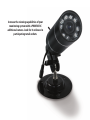
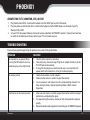
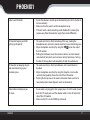
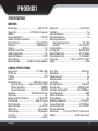
Wireless Video
Security System
Portable LCD Monitor & Indoor/
Outdoor Night Vision Camera
INSTRUCTION MANUAL
Model# PHOENIX1
V 1.0
Increase the viewing capabilities of your
monitoring system with a PHOENIX1C
additional camera. Look for it online or in
participating retail outlets.
!IMPORTANT! PLEASE READ!
NEED HELP?
PLEASE DO NOT RETURN THIS PRODUCT TO THE STORE
Please contact a DEFENDER customer support representative first regarding any additional information on
product features, specifications or help with set-up. Please contact us via one of the methods below:
Email:
[email protected]
Online live web chat:
www.defender-usa.com/support
Toll free telephone:
1.866.946.7828
Toll free fax:
1.888.771.1701
Note: You may find updated versions by visiting our website at www.defender-usa.com
PHOENIX1
WWW.DEFENDER-USA.COM
PRODUCT WARRANTY INFORMATION
Please visit our website at www.defender-usa.com
for information about your product’s warranty.
We take quality very seriously. This is why all of our products come with a one year warranty from the original purchase date
against defects in workmanship and materials. If you have warranty or support issues please contact us using any of the following
methods:
Phone: 1.866.946.7828
Fax: 1.888.771.1701
Email: [email protected]
Website: www.defender-usa.com
DEFENDER Canada
4080 Montrose Road
Niagara Falls, ON
Canada, L2H 1J9
DEFENDER USA
2315 Whirlpool St., Unit 333
Niagara Falls, New York
USA, 14305
Warranty Terms
1.
2.
3.
4.
5.
6.
7.
8.
9.
Defender products are guaranteed for a period of one year from the date of purchase against defects in workmanship and materials. This warranty is limited to the repair, replacement or refund of the purchase price at Defender’s option.
This warranty becomes void if the product shows evidence of having been misused, mishandled or tampered with contrary to the applicable instruction manual.
Routine cleaning, normal cosmetic and mechanical wear and tear are not covered under the terms of this warranty.
The warranty expressly provided for herein is the sole warranty provided in connection with the product itself and no other warranty, expressed or implied is provided. Defender assumes no responsibilities for any other claims not specifically mentioned in this warranty.
This warranty does not cover the shipping cost, insurance or any other incidental charges.
You MUST call Defender before sending any product back for repair. You will be sent a Return Authorization form with return instructions. When returning the product for warranty service, please pack it carefully in the original box with all supplied accessories, and enclose your original receipt or copy, and a brief explanation of the problem (include RA #).
This warranty is valid only in Canada and the continental U.S.
This warranty cannot be re-issued.
Tearing the tamper-proof sticker on the DVR case will void the product warranty (if applicable).
PHOENIX1
WWW.DEFENDER-USA.COM
PHOENIX1
TABLE OF CONTENTS
TABLE OF CONTENTS.......................................................................................................1
INTRODUCTION.............................................................................................................2
WHAT IS INCLUDED........................................................................................................2
FEATURES....................................................................................................................3
OPTIONAL ACCESSORIES.................................................................................................4
THINGS TO CONSIDER BEFORE INSTALLATION....................................................................4
AVOIDING INTERFERENCE...............................................................................................4
INSTALLATION...............................................................................................................5
INSTALLING THE CAMERA (TRANSMITTER)..............................................................5
INSTALLING AN ADDITIONAL CAMERA....................................................................5
SETTING THE CAMERA CHANNELS..........................................................................6
SETTING UP THE LCD MONITOR (RECEIVER).............................................................7
USING THE CHARGING BASE.................................................................... 7
CONNECTING DIRECTLY TO THE LCD MONITOR........................................... 8
OPERATION...................................................................................................................9
MONITOR FUNCTIONS..........................................................................................9
POWERING ON..................................................................................................10
OPERATING MODES............................................................................................10
MANUAL MODE.................................................................................................10
SCAN MODE......................................................................................................11
AUTO MODE......................................................................................................12
CHANGING THE CYCLE/DWELL TIME IN AUTO MODE................................................14
CONNECTING TO A TV/VCR/DVR.....................................................................................14
LITHIUM BATTERY TIPS......................................................................................15
CONNECTING TO TV, MONITOR, VCR, OR DVR.........................................................16
TROUBLESHOOTING.....................................................................................................16
SPECIFICATIONS..........................................................................................................18
MONITOR.........................................................................................................18
CAMERA SPECIFICATIONS...................................................................................18
PHOENIX1
1
PHOENIX1
INTRODUCTION
Congratulations on your purchase of the PHOENIX1! This system consists of a wireless camera, which transmits
video and audio signals to a handheld color LCD monitor. The PHOENIX1 allows you to see and hear events which are
happening in other areas of your home or business when you are not present.
WHAT IS INCLUDED
PHOENIX1
2
PHOENIX1
FEATURES
PHOENIX1
3
PHOENIX1
OPTIONAL ACCESSORIES
• PHOENIX1C (Additional Wireless Camera)
For updated optional accessories please visit our website:
WWW.DEFENDER-USA.COM
THINGS TO CONSIDER BEFORE INSTALLATION
For best performance, follow these simple guidelines:
• Camera(s) should be installed between 8 and 13 feet above the area to be monitored.
• For best transmission, avoid installations where there are thick walls or major obstructions between the camera and receiver.
• To maximize viewing area, ensure there are no obstructions in the camera’s view.
AVOIDING INTERFERENCE
The PHOENIX1 utilizes Clear Signal Technology, meaning that it is designed to avoid the frequencies of common
wireless devices. By doing so, the system does not receive interference from any of the standardized 2.4GHz or 5.8 GHz
wireless devices within your home or business.
The signal also passes easily through interior walls. However, buildings with metal frames or placing the camera near
large metal objects may cause signal interference. If reception is poor, moving the camera or receiver may fix this
problem. Interference is also possible if another device within the building (such as a cordless phone) is operating on
a 900MHz frequency.
PHOENIX1
4
PHOENIX1
INSTALLATION
INSTALLING THE CAMERA (TRANSMITTER)
1. Decide whether the camera will be wall-mounted or sit on a desk/
tabletop. If wall mounting, use the included mounting hardware. The
camera can be adjusted for either mounting scenario by rotating/
adjusting the camera to the required position.
Desk Mounted
Camera
2. Connect the AC power adapter to the camera. Make sure that the camera is positioned less than 6 ½ feet (the power
cord is only 6 ½ feet in length) from a power adapter and connect the power plug to the outlet.
The camera installation is now complete!
Note: If you are using an additional camera (not included) you will need to have one camera set to channel 1 and the other set to channel 2. For more information, see “Installing an Additional Camera”, below
INSTALLING AN ADDITIONAL CAMERA
The PHOENIX1 is designed to work with up to two cameras, allowing you to effectively monitor more than one area
at a time. If you are using an additional camera (not included) they will need to be set on different channels. The
PHOENIX1 is set by default to operate with one camera. If you will be using two cameras, follow the instructions on
next page.
PHOENIX1
5
PHOENIX1
SETTING THE CAMERA CHANNELS
1. Verify the camera’s channel setting by verifying the DIP switch settings. To do this, unscrew the front part of the
camera to open the lens cover and adjust the DIP switches. PHOENIX1 cameras are set by default to Channel 1.
2. Use a pen or pointed object to flip the DIP switches up or down according to the image below. Make sure that one
camera is set to the Channel 1 position and the other camera is set to the Channel 2 position.
Note: This is very small and may be hard to see. Appropriate lighting needed
3. Accordingly, the DIP switch located on the bottom of the monitor should be adjusted to reflect the use of multiple channels. The monitor will be set by default to channel 1 only. To be able to view both cameras you need to adjust
the DIP switches on the bottom of the monitor to reflect all channels in use.
4. Use a pen or pointed object to flip the DIP switches
down according to the image (right). This way the
monitor will be able to display video from both cameras.
PHOENIX1
6
PHOENIX1
SETTING UP THE LCD MONITOR (RECEIVER)
There are two methods to power the LCD monitor and to charge the batteries:
USING THE CHARGING BASE
1. Plug the power adapter into an AC power outlet.
2. Connect the LCD monitor power adapter to the DC IN 9V
jack on the back of the charging base.
3. Place the charging base so that the green light on the
base is facing towards you. Place the monitor into the
base with the monitor’s antenna pointing up and the
LCD screen facing towards you. A red LED light on the
side of the monitor will turn on to show that the unit is
connected to power and the battery is charging.
4. Turn on the PHOENIX1 by pressing the button. You will hear an audible beep and the sound indicator
lights on the monitor will blink. The screen will display
video from your mounted camera.
Note: If the LCD monitor beeps continuously, it means that the
camera’s microphone is detecting sounds loud enough
to trigger the audio alarm. To disable this alert, turn
down the
(audio sensitivity) dial on the side of
the monitor by turning the dial down all the way, or until
the beeping stops.
PHOENIX1
7
PHOENIX1
CONNECTING DIRECTLY TO THE LCD MONITOR
1. Plug the power adapter in to an AC power outlet.
2. Plug the power adapter in to the DC IN 9V jack on the
side of the monitor. A red LED light on the side of the
monitor will turn on to show that the unit is connected
to power and the battery is charging.
3. Turn on the PHOENIX1 by pressing the
button. You
will hear an audible beep and the sound indicator lights
on the monitor will blink. The screen will display video
from your mounted camera.
The LCD monitor is now ready to use!
INSTALLATION TIP:
After installing your camera and monitor, you may wish to place an object like a TV or radio in the monitoring area.
You can use the volume on the TV or radio to set the audio sensitivity on the LCD monitor. By adjusting the volume on
the TV/radio and the sensitivity on the LCD monitor you can discover what level of noise will trigger an audio alert.
This way you will not be alerted by false alarms or miss any sounds that are above a normal sound level.
PHOENIX1
8
PHOENIX1
OPERATION
MONITOR FUNCTIONS
PHOENIX1
9
PHOENIX1
POWERING ON
Turn on the monitor by pressing the . You will hear an audible beep and the LED lights will blink. The screen will
display video from your mounted camera.
The red LEDs at the top of the monitor indicate the level of sound the microphone is detecting. The first two lights
indicate a quiet sound level, the middle light indicates moderate, and the fourth and fifth lights indicate loud sounds
taking place in the area you are monitoring.
To adjust microphone sensitivity, use the
on the side of the LCD monitor. Turning the up causes the camera
to become more sensitive to sound and prone to more frequent alerts on the monitor. Turning the down causes
the camera to be less sensitive towards sound and will only alert you in instances of very loud
noises. The LEDs at the top of the monitor will still blink to indicate the level of noise occurring in
your monitoring location.
You can also adjust the level of audio volume on your LCD monitor. Press the V+ button to make
the audio louder or press the V- button to turn down the volume.
OPERATING MODES
The system can be set to operate in one of three modes: Scan, Auto, or Manual. The desired
operating mode can be selected using the buttons on the front panel of the LCD monitor.
Note: Two cameras are required to operate in Auto mode.
MANUAL MODE
Pressing the M button places the system in Manual mode. In this mode, the monitor will display
continuous video and audio on your LCD screen and alert you with a beep when any loud sounds
occur in the area you are monitoring. To disable this alert, turn down the
(audio
sensitivity) dial on the side of the monitor by turning the dial down all the way.
PHOENIX1
10
PHOENIX1
Use manual mode if you want to view continuous video with sound. You will also
be alerted if there are any sound disturbances in the area you are monitoring. If
you are using more than one camera, you will be able to choose which camera to
view, and how long you wish to view it.
1. Press the M button. The monitor will display video and audio from your monitoring location.
2. If the camera detects sound above the desired sound trigger level, the monitor will beep and will display video
and sound from your monitoring location. The Channel 1 or Channel 2 indicator light will also turn on to let you
know where your video is coming from.
3. IF USING TWO CAMERAS: pressing M will display video and audio from Camera 2. If you wish to
view video from camera 1, press the M button again. You will see the Camera 1 indicator light
switch on and you will see video from camera 1 on your LCD screen. You can switch back and
forth between cameras at any time by pressing the M button.
SCAN MODE
Pressing the SCAN button places the system in scan mode. Use scan mode if you do not wish to watch
continuous video with sound but want to be alerted if there are any sound disturbances in the area
you are monitoring. To disable this alert, turn down the
(audio sensitivity) dial on the side of
the monitor by pushing the dial down all the way.
1. Press the SCAN button. You will hear an audible beep and then the screen will go blank. The
camera is now scanning active cameras. The screen will stay black until the camera detects sound
above the desired sound trigger level.
PHOENIX1
11
PHOENIX1
SCAN MODE continued...
2. If the camera detects sound above the desired sound trigger level, the monitor will beep and will display video and
sound from your monitoring location. The Channel 1 or Channel 2 indicator light will also turn on to let you know
where your video is coming from
3. To return back to scanning with a blank screen and no audio, press the SCAN button again.
IF USING TWO CAMERAS: After sending an audio alert to the monitor, video from
that specific camera will be displayed on screen. The monitor will then beep every
time the camera detects noise above the preset sound trigger level. After a four
second period with no audio disturbance, the monitor will then cycle back and
forth between both cameras and display video and audio on the monitor. This
switch will occur every four seconds.
AUTO MODE
Note: Two cameras are required to operate in Auto mode. If you place the system
into Auto mode when there is only one camera, the system will not function properly. If you only have one camera installed, use SCAN or Manual mode for effective
monitoring.
Pressing the A button places the system in Auto mode. While in Auto mode the
system will scan between both channels at a set dwell/cycle time (time to switch
between cameras). The default is four seconds, but can be adjusted to a specific
time between 2-30 seconds. For more information on changing the cycle/dwell
time, see “Changing the Cycle/Dwell Time in Auto Mode”.
In Auto mode, the monitor will cycle through video and audio from both cameras
on your LCD monitor. Auto mode also alerts you with a beep if any loud sounds
occur in the area you are monitoring.
PHOENIX1
12
PHOENIX1
AUTO MODE continued...
Use Auto mode if you want to be able to view video from both cameras and receive audio alerts if there are any sound
disturbances in either monitoring areas. To disable this alert, turn down the
(audio sensitivity) dial on the side
of the monitor by pushing the dial down all the way.
1. Press the A button. The monitor will display video and audio from your camera 2 monitoring location and the
Camera 2 indicator light will be on.
2. If you wish to view video from camera 1, press the A button again. You will see the Camera 1 indicator light turn
on and you will see video from camera 1 on your LCD screen. Otherwise the picture on the LCD screen and audio
on the monitor will switch back and forth from camera 1 to camera 2 every four seconds.
3. If the camera detects sound above the desired sound trigger level, the monitor will beep and will display video
and sound from your monitoring location. The Channel 1 or Channel 2 indicator light will also turn on to let you
know where your video is coming from.
PHOENIX1
13
PHOENIX1
CHANGING THE CYCLE/DWELL TIME IN AUTO MODE
You can change the dwell/cycle time (time interval to switch between cameras) so that the video switches more or less
frequently:
a) Press and hold down the M and A buttons simultaneously. You will hear the monitor begin to beep.
b) The first beep will signify one second and every beep afterwards increases the dwell time by one second. For
example, if you would like the dwell/cycle time to be 12 seconds you will have to hold down the M and A buttons
until you hear the monitor beep 12 times.
c) When you reach the desired number of seconds, release the
M and A buttons.
d) You will hear the monitor beep again at a quicker rate. This
will confirm the new duration of the dwell/cycle time (12
beeps equal a 12 second cycle dwell time).
e) To change the duration time again, press and hold down the
M and A buttons until you reach a desired interval time.
f) When you are finished setting a new duration press the A
button again to view video with your new dwell cycle time.
Note: Every time you power off the PHOENIX1, the dwell/cycle defaults back
to four seconds.
CONNECTING TO A TV/VCR/DVR
You can connect to a TV for viewing or to a VCR/
DVR for recording.
In order to view and record video from your
PHOENIX1 system, your TV/VCR/DVR must have
video input jacks.
PHOENIX1
14
PHOENIX1
LITHIUM BATTERY TIPS
The rechargeable battery of the handheld monitor is a built-in lithium-polymer battery. Before using the monitor with
battery power, please read the following in order to use the battery properly.
1.
2.
3.
4.
5.
6.
7.
8.
9.
10.
11.
12.
13.
14.
Under normal temperatures the battery can be recharged at least 300 times.
If the battery is not already full, make sure that the battery is charged before use.
When the device is not in use, switch the unit off to maintain battery power.
During charging, the battery charging indicator light will turn red and then change to green once the charge is complete.
The monitor will alert you when your battery is running very low on power. The blue power light will begin to blink, and the monitor will beep twice before the unit shuts off entirely.
Unplug the power adapter when not in use.
In colder environments, the unit will consume more power. Please keep this device at room temperature to
increase the usable power. In environments with low temperatures it will take longer to recharge than in normal
temperature environments.
To avoid danger, do not use the power adapter in high temperature and high humidity locations.
It is normal for the unit’s battery to feel slightly warm while the monitor is in use or is charging. Do not leave the power adapter connected for an extended period of time.
For your own safety, the battery is set to stop charging when the battery temperature is higher than 45°C or lower than 5°C. Charging will automatically resume once temperatures are back to normal.
In order to avoid damaging the battery, do not expose the monitor to high temperature environments (45°C
or above)
Even if the battery is fully charged, power will gradually be lost if the monitor is not used for an extended period. Make sure to recharge if the unit has not been in use for a long period of time.
Always use the supplied power adapter only to recharge the monitor’s battery. Using any other power adapter could ruin the monitor or cause extreme burns.
Do not attempt to disassemble the battery, it is very dangerous and voids your warranty.
PHOENIX1
15
PHOENIX1
CONNECTING TO TV, MONITOR, VCR, OR DVR
1.
2.
3.
Plug the black end of the 3.5mm to RCA adapter into the AV OUT port on the LCD monitor.
Plug the yellow and white ends of the 3.5mm to RCA adapter into the VIDEO IN ports on the back of your TV, Monitor, VCR, or DVR.
Set your TV to the proper Video Input channel to view video from the PHOENIX1 monitor. If you do not know how to switch to the Video Input channel, refer to your TV’s instruction manual.
TROUBLESHOOTING
If you are having trouble operating this product, please consult the guide below.
PROBLEM
SOLUTION
The monitor has no power. When
pressing the ON button there is no
camera display and no lights blink.
1. Check that the monitor is turned on.
2. The battery may have no charge. Plug the AC adapter directly in to the
DC IN 9V jack on the monitor.
3. If using the charging base, check to make sure it is connected to AC
power and that the monitor is sitting in the base properly.
No camera picture
1. Check all connections and AC adapters.
2. Make sure the camera is within range of the receiver.
3. Ensure camera(s) and receiver are set to corresponding channels. For
help setting channels, refer to Operating Modes>Multi-Camera
Operations .
Interference on the camera picture
1. Make sure each camera is within range of the monitor and that no larger
obstructions are blocking the signal.
2. Try repositioning the camera, monitor, or both to improve the reception
quality.
3. Reposition other nearby equipment transmitting on the 900MHz frequency.
PHOENIX1
16
PHOENIX1
Audio Issues/No Audio
1. Ensure the volume is turned up on the monitor (press the V+ button to
increase volume)
2. Make sure that the sound is within microphone range
3. If the unit emits a loud screeching sound (feedback) try moving the
camera away from the monitor or angle the monitor differently
LCD monitor beeping and LEDs
lighting up frequently
1. The audio sensitivity is likely turned up all the way, making the
microphone very sensitive to sounds occurring in your monitoring area.
2. Adjust microphone sensitivity by using the
dial on the side of
the LCD monitor.
3. Pulling the dial down causes the camera to be less sensitive towards
sound and will only alert you in instances of very loud noises. Turning
the dial all the way down will completely disable the audio alarm.
LCD monitor not beeping despite
loud sound occurring in your
monitoring area
1. The audio sensitivity is likely turned down, or the alarm feature is
disabled.
2. Adjust microphone sensitivity by using the [Graphics: insert audio
sensitivity dial graphic] dial on the side of the LCD monitor.
3. Pushing the dial up causes the camera to become more sensitive to
sound and prone to more frequent alerts on the monitor.
Video/Audio not displaying on
TV screen
1. Ensure cables are plugged in their proper places: the RCA cables should
be in the TV’s input jacks and the adapter cable is in the AV out on the
side of the LCD monitor
2. Make sure the TV is on the VIDEO input channel
PHOENIX1
17
PHOENIX1
SPECIFICATIONS
MONITOR
Monitor Type................................................Color TFT-LCD
Screen Size.................................2.25"Wireless Frequency
900MHz
Channel Frequencies...........................................910, 920
Number of Cameras Supported.......................................2
Output Terminal...................................... 3.5mm A/V Port
Resolution.................................................480X240 pixels
Speaker........................................................................Yes
Motion Activated Alert................................................. No
Audio Activated Alert...................................................Yes
Audio Alert Volume..................................................90 dB
Auto-Scanning.............................................................Yes
Battery Operable................ Yes, Built-in Lithium-polymer
CAMERA SPECIFICATIONS
Image sensor.......................................... 1/3" CMOS Color
Outdoor use................................................................. Yes
IP Rating.................................................................... IP54
Wireless
Maximum Range................................ 300ft. (Open Space)
Optimum Range................Up to 75 ft. (Line of Sight)
Wireless Frequency....................................... 900MHz
Channel Frequencie......................................910, 920
Resolution.................................... 360 Horizontal TV Lines
Night Vision.................................................................. Yes
Number of IR LEDs and Range.......................8, Up to 10ft.
IR LED control..........................................Auto, CDS sensor
Min. Illumination......................................................0 Lux
Battery Operable............................................. Yes (9-volt)
Battery Life..................................................Up to 4 Hours
Viewing Angle..............................................60° (degrees)
TV System................................................................. NTSC
Focal Length......................................................... 6.0 mm
PHOENIX1
Battery Life ..................................................Up to 4 Hours
Handheld...................................................................... Yes
Video On/Off Button.......................................................No
Adjustable Brightness................................................... Yes
Operating Environment
Operating Temperature..............................14F~104F
Humidity............................................. Less than 85%
Housing Material...............................................ABS Plastic
Housing Color............................................. Midnight Black
Monitor Power Input...................................DC 9V 1200mA
Power Adapter Input.................................... AC 120v/60Hz
Dimensions........................... 7.563"H x 2.875"L x 1.188"D
Weight......................................................................0.4lbs
Focus Type.......................................................Fixed Focus
Microphone..................................................................Yes
Motion Detection......................................................... No
Audio Activation..........................................................Yes
Sun Shield.................................................................... No
Housing Material..............................................Aluminum
Housing Color............................................Midnight Black
Electronic shutter speed1......................./60-1/15,000 sec
Signal/Noise Ratio.....................................................48dB
Power LED Indicator..................................................... No
Camera Bracket............................................................Yes
Operating Temperature................................-4°F to 104°F
Camera Power Input.................................... DC 9V 400mA
Power Adapter Input...................................AC 120V 60Hz
Physical Specification
Dimensions.............5.5"L x 3.25"W x 2.75"D (with stand)
Weight..............................................0.45lbs (with stand)
18
DEFENDER SUPPORTS CRIME STOPPERS
Crime Stoppers programs are operated as non-profit charities and are managed by a volunteer board of directors who raise funds and pay rewards
to individuals who anonymously call with information that helps solve crime.
Rewards are paid for tips that lead to the arrest and indictment of people charged with felony offenses, and to date Crime Stoppers statistics show
a conviction rate of approximately 95%.
To receive more information about Crime Stoppers or to make a charitable donation please fill in the fields on the back of this page, cut on the
dotted line and mail in.
PLACE
POSTAGE
HERE
CRIME STOPPERS INTERNATIONAL
P.O. Box 614
Arlington, Texas
U.S.A. 76004-0614
PHOENIX1
www.defender-usa.com
DEFENDER SUPPORTS CRIME STOPPERS
To receive more information about Crime Stoppers or to make a charitable donation please fill in the fields below,
cut on the dotted line an mail in.
CRIME STOPPERS INTERNATIONAL
Crime Stoppers International is an organization of community based civilian Crime Stoppers programs, which
assist police in solving crime. You can find more information about Crime Stoppers at www.c-s-i.org.
Local Crime Stoppers programs are partnerships between the public, media and local policing organizations. Each
program is run by a citizen board, whose purpose is to advertise a local telephone number, which anonymous
persons can call with information regarding a crime. Callers (tipsters) may be eligible for a cash reward for their
information.
If your community does not have a Crime Stoppers program and would like information about starting one, return
this card with the following information.
NAME:______________________________________PHONE:_ ____________________________
ADDRESS:_ _________________________________CITY:________________________________
PROV/STATE:______________ COUNTRY:_ _____________ POSTAL/ZIP CODE:_____________
E-MAIL ADDRESS:________________________________________________________________
Charitable donations can be made to “CSI” by returning this card in an envelope with your check or money order
to the address on the other side.
Amount $
THANK YOU
PHOENIX1
www.defender-usa.com
NOTES
Customer Information Card
User’s Name:
Company Name:
Address:
Postal Code:
Phone Number:
Email:
Model Number of Product:
Serial Number of Product:
Purchase Date:
Place of Purchase:
NOTE: We recommend that you keep a record of your purchase receipt with your manual for any future returns or support issues.
Model #: PHOENIX1
www.defender-usa.com