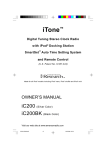
1
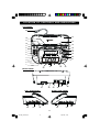
Dual Alarm AM/FM Clock Radio
with SmartSet
®
Auto Time Setting System
and Caller ID Telephone
(U.S. Patent No. 6,567,344)
OWNER’S MANUAL
CKT9087
Visit our web site at www.emersonradio.com
CKT9087_090606.p65
40
6/9/2006, 10:56
CAUT I ON
TO PREVENT FIRE OR SHOCK HAZARD, DO NOT USE THIS PLUG WITH AN
EXTENSION CORD, RECEPTACLE OR OTHER OUTLET UNLESS THE BLADES
CAN BE FULLY INSERTED TO PREVENT BLADE EXPOSURE. TO PREVENT FIRE
OR SHOCK HAZARD, DO NOT EXPOSE THIS APPLIANCE TO RAIN OR MOISTURE.
C AU T I O N
RISK OF ELECTRIC SHOCK
DO NOT OPEN
The lightning flash with arrowhead symbol, within an equilateral triangle is intended to
alert the user to the presence
of uninsulated ‘dangerous voltage’
within the product’s enclosure
that may be of sufficient
magnitude to constitute a risk
of electric shock to persons.
WARNING: TO REDUCE THE
RISK OF ELECTRIC SHOCK
DO NOT REMOVE COVER
(OR BACK), NO USER
SERVICEABLE PARTS INSIDE
REFER SERVICING TO
QUALIFIED SERVICE
PERSONNEL.
!
The exclamation point within
an equilateral triangle is intended to alert the user to
the presence of important
operating and maintenance
(ser vi ci ng) instr ucti ons in
the liter ature accompanying the appl iance.
IMPORTANT SAFETY INSTRUCTIONS
When using your telephone equipment, basic safety precautions should always be
followed to reduce the risk of fire, electric shock and injury to persons, including the
following:
1.) Read these instructions.
2.) Keep these instructions.
3.) Heed all warnings.
4.) Follow all instructions.
5.) Do not use this product near water, for example, near a bath tub, wash bowl,
kitchen sink, or laundry tub, in a wet basement, or near a swimming pool.
6.) Cleaning. Unplug this product from the wall outlet before cleaning. Do not use
liquid cleaners or aerosol cleaners. Use a damp cloth for cleaning.
7.) Do not block any ventilation openings. Install in accordance with the
manufacturer’s instructions.
8.) Do not install near any heat sources such as radiators, heat registers, stoves,
or other apparatus (including amplifiers) that produce heat.
9.) Do not defeat the safety purpose of the polarized or grounding-type plug. A
polarized plug has two blades with one wider than the other. A grounding type
plug has two blades and a third grounding prong. The wide blade or the third
prong is provided for your safety. If the provided plug does not fit into your outlet,
consult an electrician for replacement of the obsolete outlet.
10.) Protect the power cord from being walked on or pinched particularly at plugs,
convenience receptacles, and the point where they exit from the apparatus.
1
CKT9087_090606.p65
1
6/9/2006, 10:56
11.) Only use attachments / accessories specified by the manufacturer.
12.) Unplug this apparatus during lightning storms or when unused for long periods
of time.
13.) Refer all servicing to qualified service personnel. Servicing is required when
the apparatus has been damaged in any way, such as power-supply cord or
plug is damaged, liquid has been spilled or objects have fallen into the
apparatus, the apparatus has been exposed to rain or moisture, does not
operate normally, or has been dropped. When the product exhibits a distinct
change in performance – this indicates a need for service.
14.) This appliance shall not be exposed to dripping or splashing water and no
object filled with liquids such as vases shall be placed on the apparatus.
15.) Do not overload wall outlet. Use only power source as indicated.
16.) Use replacement parts as specified by the manufacturer.
17.) The product may be mounted to a wall only if recommended by the manufacturer.
18.) Upon completion of any service or repairs to this product, ask the service
technician to perform safety checks.
19.) Avoid using a telephone (other than a cordless type) during an electrical storm.
There may be a remote risk of electric shock from lightning.
20.) Do not use the telephone to report a gas leak in the vicinity of the leak.
21.) Power Lines – An outside antenna system should not be located in the vicinity
of overhead power lines or other electric light or power circuits, or where it
can fall into such power lines or circuits. When installing an outside antenna
system, extreme care should be taken to keep from touching such power
lines or circuits as contact with them might be fatal.
22.) Object and Liquid Entry – Never push objects of any kind into this product
through openings as they may touch dangerous voltage points or short-out
parts that could result in a fire or electric shock. Never spill liquid of any kind
on the product.
23.) Power Sources – This product should be operated only from the type of power
source indicated on the marking label. If you are not sure of the type of power
supply to your home, consult your product dealer or local power company.
For products intended to operate from battery power, or other sources, refer
to the operating instruction.
24.) Do not dispose of batteries in a fire. They may explode. Check with local
codes for possible special disposal instructions.
SAVE THESE INSTRUCTIONS
2
CKT9087_090606.p65
2
6/9/2006, 10:56
Thank you .......................
for purchasing this Emerson Research SmartSet® Dual Alarm, Caller ID
Telephone Clock Radio.
This compact multi-function unit is designed to replace two separate devices
that you probably have on your night table now, but with special features
available only from Emerson Research. The patented SmartSet® Automatic
Time Setting System will set the clock to the correct year, month, day,
date, and time as soon as you plug it in, and after every power interruption.
It also automatically adjusts from Standard Time to Daylight Saving Time
through the year 2099! Leap Years too! The dual alarms can be set
separately to wake you to radio or buzzer, on weekdays only, weekends
only, or all seven days. The long life lithium battery is already installed and
it will maintain your settings from 5 to 8 years before it needs replacing.
And of course the large, super-bright ‘RED’clock display is visible from
anywhere in your room.
The telephone handset has 13 memories for frequently dialed numbers,
including 3 one-touch, speed-dial buttons that you can use for emergency
numbers. The Caller ID system has a lighted display and an 80 number
Caller ID memory. You can automatically dial any number in the Caller ID
memory at the touch of a button. And of course we’ve included the Call
Waiting feature that will signal to let you know that another caller is trying
to reach you.
We have taken great care to insure that every component in your set was
in perfect working order when it left our factory. If, after reading this Owners
Manual, you have any problems with the set up or operation of this product,
please call the Emerson Consumer Products Customer Service Hotline
toll-free at 800-898-9020. The hours of operation are 9:00 AM to 5:00 PM
Central Time.
Once again, from everyone at Emerson Radio Corporation, thanks for
purchasing this SmartSet® Telephone Clock Radio.
Note: Call Waiting and Caller ID are special subscription services
provided by your local telephone service provider. If you do not
have these services and you wish to subscribe, contact your local
telephone company for fees, terms, and conditions.
3
CKT9087_090606.p65
3
6/9/2006, 10:56
I M P O R TAN T N O T E S
• Avoid installing this unit in places • Operate controls and switches as
described in the manual.
exposed to direct sunlight or close to
heat radiating appliances such as • Before turning on the power, make
electric heaters, on top of other stereo
certain that the power cord is properly
equipment that radiates too much
installed.
heat, places lacking ventilation or dusty
areas, places subject to constant
vibration and/or humid or moist areas.
• When moving the set, be sure to first
disconnect the power cord and remove
cords connected to other equipment.
FCC INFORMATION
This equipment has been tested and found to comply with the limits for a Class B
digital device, pursuant to Part 15 of the FCC Rules. These limits are designed to
provide reasonable protection against harmful interference in a residential
installation. This equipment generates, uses, and can radiate radio frequency energy
and, if not installed and used in accordance with the instructions, may cause harmful
interference to radio communications. However, there is no guarantee that
interference will not occur in a particular installation. If this equipment does cause
harmful interference to radio or television reception, which can be determined by
turning the equipment off and on, the user is encouraged to try to correct the
interference by one or more of the following measures:
• Reorient or relocate the receiving antenna.
• Increase the separation between the equipment and receiver.
• Connect the equipment into an outlet on a circuit different from that to which
the receiver is connected.
• Consult the dealer or an experienced radio/TV technician for help.
This device complies with Part 15 of the FCC Rules. Operation is subject to the
following two conditions:
(1) This device may not cause harmful interference, and
(2) This device must accept any interference received, including interference
that may cause undesired operation.
Changes or modifications not expressly approved by the party responsible for
compliance could void the user’s authority to operate the equipment.
4
CKT9087_090606.p65
4
6/9/2006, 10:56
FCC wants you to know
This equipment complied with part 68 of the FCC rules and ACTA technical
requirements. On the bottom of the base of this equipment is a label that contains,
among other information, the FCC Registration Number and Ringer Equivalence
Number (REN) for this equipment. You must, upon request, provide this information
to your telephone company.
The USOC number of the registration jack for the equipment is RJ11C.
The FCC compliant telephone cord and modular plug is provided with this
equipment. This equipment is designed to be connected to the telephone network
or premises wiring using a compatible modular jack which is TIA/EIA-IS-968
complaint.
If your telephone equipment caused harm to the telephone network, the telephone
company may discontinue your service temporarily. If possible, they will notify you
in advance. But, if advance notice isn’t practical, you will be notified as soon as
possible. You will be informed of your right to file a complaint with the FCC.
Your telephone company may make changes in its facilities, equipment, operations
or procedures that could affect the proper functioning of your equipment. If they
do, you will be notified in advance to give you an opportunity to maintain
uninterrupted telephone service. If you experience trouble with this telephone
equipment, the telephone company may ask that you disconnect this equipment
from the network until the problem has been corrected or until you are sure that
the equipment is not malfunctioning.
This equipment cannot be used on telephone company provided coin service.
Connection to Party Line Service is subject to state tariffs.
This equipment is hearing aid compatible.
Warnings:
• Any changes or modifications not expressly approved by the party responsible
for compliance could void the user’s authority to operate the equipment.
• When your telephone is not in use, make sure the handset is engaged into the
base unit.
• If it is determined that your telephone is malfunctioning, the FCC required that
it be disconnected from the modular outlet until the problem has been corrected.
Ringer Equivalence Number (REN)
The Ringer Equivalence Number is used to determine how many devices can be
connected to your home telephone line. The REN of this unit is 1.0B. The total
REN of all the devices connected to your line should not exceed 5.0.
If you exceed this total then one or more of the devices may not ring when a call is
received.
5
CKT9087_090606.p65
5
6/9/2006, 10:56
P R E PAR AT I O N F O R U S E
UNPACKING AND SET-UP
• This carton contains the telephone clock radio base unit, the telephone
handset, the coiled cord that connects that handset to the base unit,
and the straight telephone line cord that connects the telephone base
unit to your telephone wall jack. Make sure that you remove all of the
components from the carton and that nothing is accidentally thrown
away with the packing materials.
Remove all the packing materials from the individual components.
• We suggest that you save the packing materials, if possible, in the
event that the unit ever needs to be returned for service. Using the
original carton and packing material is the only way to properly protect
the unit from possible shipping damage.
• Note the serial number on the bottom of your unit and write this number
in the space provided on Warranty Page of this manual.
• Place the base unit on a stable, level surface such as a table, desk,
stand, etc, out of direct sunlight, away from sources of excess heat,
dust, vibration, moisture, or humidity, and convenient to a 120V/60Hz
AC outlet and a telephone wall jack.
• Unwind the AC power cord and extend it to its full length. This is
important. The FM antenna is built into the AC power cord.
6
CKT9087_090606.p65
6
6/9/2006, 10:56
Installing The Telephone Memory Back-up Battery
This unit requires a 9-Volt battery, not included, to maintain the telephone caller ID
and speed-dial number memories in the event of a temporary power interruption.
Be sure to use a well-known brand of alkaline battery for longest life and best
performance. If you do not install the back up battery, any numbers that you have
entered into the speed dialing memories, and numbers that have been automatically
recorded in the caller ID memories, may be erased if the AC power supply is
interrupted.
Install the telephone memory back-up battery as follows:
1.) Turn the telephone base unit upside-down. To prevent scratches to the base
unit, place it on a soft surface such as a towel or blanket as you perform this
procedure.
SLI DE TO OP
EN
2.) Press down on the engraved “arrow” on the
battery compartment door and slide the door
in the direction of the arrow to remove it.
3.) Attach the 9-volt battery to the terminals
of the battery harness as shown.
It can only be attached one way.
4.) Push the battery back into the battery compartment and replace the battery
door. Turn the base unit right side up again.
7
CKT9087_090606.p65
7
6/9/2006, 10:56
Low Battery Indication (
)
When the 9-Volt battery becomes weak, a low battery-warning indicator
will
appear in the Caller ID display.
When you see this indicator you should replace the 9-Volt battery as soon as
possible. To avoid losing the numbers stored in the handset memory or the Caller
ID memory, leave the base unit connected to the AC outlet while you are changing
the battery.
Connecting The Telephone Cords
Line Cord
Unwind the straight telephone line cord. First connect one end of this cord to the
modular socket marked “LINE”on the back of the telephone base unit. Then connect
the other end of the cord to your telephone wall jack.
Telephone Wall Jack.
Push the modular plugs all the way in to the sockets until a ‘click’is heard and the
cords are locked in place.
Note: If you have some other type of telephone jack, such as a 3-pin connector
jack, you will have to buy an appropriate modular to 3-pin connector plug,
available wherever telephone accessories are sold.
8
CKT9087_090606.p65
8
6/9/2006, 10:56
Coiled Handset Cord
First connect one end of the coiled cord to the modular socket on the bottom of the
handset. Then connect the other end of the coiled cord to the socket marked
“HANDSET” on the back of the telephone base unit.
Push the modular plugs all the way into the sockets until a click is heard and the
plugs are locked in place.
Disconnecting The Telephone Cords
To disconnect either the straight cord or the coiled cord from the modular sockets,
squeeze the plastic locking tab on the plug to release the lock and pull the plug out
of the socket.
9
CKT9087_090606.p65
9
6/9/2006, 10:56
POWER SOURCE
The model is designed to operate on 120V AC 60Hz house current only. Attempting
to operate this model by any other power source could cause damage to the unit,
and such damage is not covered by your warranty.
Make sure that you connect the power cord to an AC outlet that is always ‘live’. Do
not connect to an AC outlet that is controlled by a wall switch. This SmartSet ®
clock radio uses a long life lithium battery to maintain the time and alarm setting
during temporary power interruptions. When the clock radio is connected to a ‘live’
AC outlet the back-up battery goes into a ‘standby’ mode to preserve power.
Therefore keep the unit connected to a ‘live’outlet at all times to extend the life of
the lithium battery.
You will note that this system is equipped
with a polarized AC power plug having
one blade wider than the other. This is a
safety feature. If this plug does not fit into
your existing AC outlet, do not try to
defeat this safety feature by filing the
wide blade to make it fit into your outlet.
If this plug will not fit into your outlet, you
probably have an out-dated nonpolarized AC outlet. You should have
your outlet changed by a qualified
licensed electrician.
AC Outlet
AC Plug
PROTECT YOUR FURNITURE
This model is equipped with non-skid rubber 'feet' to prevent the product from
moving when you operate the controls. These 'feet' are made from non-migrating
rubber material specially formulated to avoid leaving any marks or stains on your
furniture. However certain types of oil based furniture polishes, wood preservatives,
or cleaning sprays may cause the rubber 'feet' to soften, and leave marks or a
rubber residue on the furniture. To prevent any damage to your furniture we strongly
recommend that you purchase small self-adhesive felt pads, available at hardware
stores and home improvement centers everywhere, and apply these pads to the
bottom of the rubber 'feet' before you place the product on fine wooden furniture.
10
CKT9087_090606.p65
10
6/9/2006, 10:56
L O C AT I O N O F C O N T R O L S AN D I N D I C AT O R S
TOP PANEL
29
13
12
11
14
10
9
8
7
15
16
17
18
19
6
5
20
4
3
2
21
1
25
23
24
22
BACK PANEL
31
30
LEFT SIDE PANEL
32
33
29
28
27
26
RIGHT SIDE PANEL
35
34
36
11
CKT9087_090606.p65
11
6/9/2006, 10:56
37
TOP PANEL
1.) ALM 1 ‘On’Indicator.
2.) AM indicator.
3.) Day LED Indicators.
4.) TIME ZONE Button.
5.) TIME Setting Button.
6.) SET – Button.
7.) SET + Button.
8.) MONTH/DATE Setting Button.
9.) ALM (Alarm) MODE (Weekdays/Weekends/Everyday Alarm) Button.
10.) SLEEP (Sleep To Music Timer) Button.
11.) ALM (Alarm) 1 setting Button.
12.) SNOOZE Button.
13.) Telephone Handset.
14.) ALM (Alarm) 2 setting Button.
15.) RADIO ON/OFF Button.
16.) NEW CALL Indicator.
17.) BATTERY LOW Indicator.
18.) RECALL UP Button.
19.) RECALL DOWN Button.
20.) DIAL Button.
21.) DELETE Button.
22.) Telephone LCD Display.
23.) ALM 2 ‘On’Indicator.
24.) Lighted Dial Pointer.
25.) Clock Time/Date Display.
12
CKT9087_090606.p65
12
6/9/2006, 10:56
BACK PANEL
26.) Telephone HANDSET Connect Jack.
27.) Telephone LINE Connect Jack.
28.) Telephone RINGER (HI/LOW/OFF)Selector Switch.
29.) AC Power Cord.
30.) Telephone Back Up Battery Compartment.
31.) Clock Back Up Battery Compartment.
LEFT SIDE PANEL
32.) Clock Display DIMMER (LOW/HIGH) Switch.
33.) ALM (Alarm) 1 (RADIO/BUZZER/OFF) Selector Switch.
34.) ALM (Alarm) 2 (RADIO/BUZZER/OFF) Selector Switch.
RIGHT SIDE PANEL
35.) TUNING Control.
40
36.) BAND (AM/FM) Switch.
37.) VOLUME Control.
41
TELEPHONE HANDSET
42
38.) FLASH Button.
39.) MEMORY Button.
40.) Earpiece.
43
41.) VOL (Volume) Selector Switch.
42.) M1/M2/M3 Memory Buttons.
44
39
43.) Numeric Keypad Buttons.
45
38
44.) STORE Button.
46
45.) REDIAL Button.
47
46.) PULSE/TONE Selector Switch.
47.) Mic.
48.) Telephone Cord Connect Jack.
48
13
CKT9087_090606.p65
13
6/9/2006, 10:56
Telephone LCD Display
4
5
6
7
8
3
2
1
1.) Caller ID Information.
2.) Incoming Telephone Number.
3.)
4.)
– Appears when Back Up Battery level is low..
– Appears when Telephone Line is disconnected or Handset is Off-hook.
5.) Caller Month, Date Display.
6.) Caller Time Display.
7.) Incoming Call Status:
RPT CALL # – Appears when receiving Repeat Calls.
RPT NEW CALL # – Appears when receiving Repeat New Calls.
FWD NEW CALL # or FWD RPT NEW CALL # –
Appears if the Incoming Call is from an Automatic Call Forwarding service.
TOLL – Appears if the Incoming Call is from an area code that will incur long
distance charges when you return the call.
– Appears when a 2nd call is waiting.
– Appears if a caller leaves a Voice Mail Message.
8.) Total Number of Incoming Calls.
14
CKT9087_090606.p65
14
6/9/2006, 10:56
T E L E P H O N E O P E R AT I N G I N S T R U C T I O N S
Note: This model is designed for normal residential phone service only.
It cannot be used with PABX systems.
Call Waiting and Caller ID Service Information
This SmartSet® telephone clock radio is compatible with Caller ID and Call Waiting
service provided by your local telephone company. Both the Caller ID and Call
Waiting features are not normally part of the basic telephone service package. If
you have already subscribed to these extra services, there is nothing further to do.
Your SmartSet® telephone clock radio is ready to use.
If you do not currently subscribe to Call Waiting and Caller ID services, you may
still use this SmartSet® telephone clock radio as you would any normal telephone,
however the Caller ID information will not appear in the display. If you want to take
advantage of the Call Waiting and Caller ID features of this SmartSet® telephone
clock radio you must contact your local telephone service provider and subscribe
to these services. In most cases there will be an additional monthly charge for
these services.
With the Call Waiting feature you will hear an audible signal on the telephone to
alert you that you have another call waiting. The signal may be a “click” sound or
possibly a soft “beep”. Your local phone company selects the signal sound. When
you hear that signal you may press the FLASH button on the handset to speak to
the second caller briefly, then press the FLASH button again to return to the first
caller. With the Caller ID feature you will be able to see the name and telephone
number of the calling party on the Caller ID display. You can then decide if you
wish to answer the call or not. You can also automatically call back any of the
numbers stored in the Caller ID memory, up to 80 numbers maximum. Both these
features will be explained in more detail later in this manual.
15
CKT9087_090606.p65
15
6/9/2006, 10:56
Caller ID Display Set-up and Adjustments
Entering Your Own Area Code and Adjusting The Display Contrast Level
In order for the Caller ID feature to work properly you must first enter your own
area code in the display. When you connect the base unit to your AC outlet for the
first time the display will ask for your area code as follows:
After 30 seconds the display will change to show the TOTAL calls and NEW calls
in the Caller ID memory.
1.) Depress and hold the UP button for at least 3 seconds to return to the AREA
CODE? screen. The cursor will be flashing below the first digit.
16
CKT9087_090606.p65
16
6/9/2006, 10:56
2.) Press either the UP or DOWN button to select the first digit of your area code.
Example: 9. Then press the DELETE button once to enter it in the memory.
The flashing cursor moves to the second digit.
3.) Press UP or DOWN to select the second digit, then press DELETE to enter it
in the memory The cursor moves to the third digit.
4.) Press UP or DOWN to select the third digit, then press DELETE to enter it in
the memory. The display will change from AREA CODE? to LCD CONTRAST.
The default LCD contrast level is “3”.
5.) Press the UP or DOWN buttons to adjust the contrast level between “1” (lowest
contrast) and “5” (highest contrast). The display contrast will immediately change
to match your selection. Press the DELETE button to memorize your selection.
The display will return to the TOTAL and NEW calls screen.
Note: To change the Area Code or Display Contrast settings at any time,
depress and hold the “UP” button for at least 3 seconds to return to the Area
Code screen and then repeat Steps 1 through 5 above.
17
CKT9087_090606.p65
17
6/9/2006, 10:56
Other Adjustments
There are 3 other settings that you may need to adjust before using your phone:
Telephone Ringer Level
The RINGER level switch (HI/LOW/OFF) is located on the back cabinet of the
base unit. We have set the level to “HI” at our factory. If you feel that the ring sound
is too loud, set the switch to the “LOW” position. If the switch is set to the “OFF”
position the telephone will not ring at all.
Handset Volume Level
The 3-position Handset VOL (Volume) Control is located on the side of the handset.
We have set this switch to the highest setting at our factory. If you find that the
handset volume is too loud, set this switch the medium or low position.
TONE/PULSE Dialing Selector
This switch was set to the TONE dialing position at our factory. If you do not have
Touch Tone dialing on your telephone line, set this switch to the PULSE dialing
position. If you need to switch to tone dialing temporarily, to respond to automated
telephone message prompts for example, you can simply press the ‘ TONE’
button on the telephone keypad and then press the desired number buttons. After
you hang up, the handset automatically returns to the Pulse dialing mode.
18
CKT9087_090606.p65
18
6/9/2006, 10:56
Caller ID Display Viewing Angle
All Liquid Crystal Displays (LCDs) have certain viewing angle limitations. They are
intended for viewing within a certain range and the display is clearest within that
range. If you view the display from outside of its normal viewing angle the information
on the display may seem to “fade”, or it may appear that the entire display is ‘On’.
This is a normal characteristic of LCD displays and not an indication of any problems
with your set. To compensate for this we have provided two foldable “legs” on the
bottom of the base unit.
If necessary you can unfold these two legs. This will raise the back of the base unit
cabinet slightly and may provide an improvement in the viewing angle. However
keep in mind that the Caller ID display in this model is designed for the clearest
viewing when you are looking downward at the display. If you are lying in bed
looking upward at the display you will be outside the normal viewing angle range
and the information on the display may not be visible.
19
CKT9087_090606.p65
19
6/9/2006, 10:56
Storing Numbers In The Handset Memory
You can store up to 13 of your most frequently called numbers in the handset
speed-dialing memory. The keypad buttons M1, M2, and M3 are one-touch
memories. Simply pressing any one of those buttons will immediately dial the stored
number. The keypad buttons “0” through “9” are two-touch memories. To dial a
stored number you must first press the MEMORY button, and then press the desired
number button to dial the stored number.
To store numbers:
1.) Lift the handset from the cradle.
Note: After a few seconds, you will hear the “Off the hook/hang up”
warning signal from the telephone company. You may continue through
the steps as below. However, if you are going to store many numbers,
suggest to press “Hook” button on the cradle periodically.
2.) Press the STORE button on the keypad.
3.) Dial the area code and number you wish to store. Don’t forget to dial a “1”
before the area code if necessary.
Note: The maximum number of digits that can be entered in any memory
location is 16.
4.) Press the STORE button again, and then press the desired memory location
button, either M1, M2, M3, or Number keys “0” through “9”.
5.) Repeat this procedure until you have stored up to 13 frequently dialed numbers.
To change a number stored in any memory just perform Steps 1 through 3 above
and store the new number in the desired memory location. The old number will be
deleted when the new number is stored.
20
CKT9087_090606.p65
20
6/9/2006, 10:56
Receiving Calls
Notes:
• Make sure that the RINGER switch is set to the HI(High) or LOW position. The
phone will not ring if the RINGER switch is set to the OFF position.
• If the radio is playing, the radio will automatically mute when a call is received.
• If you answer the phone on the first ring the Caller ID information will not appear
on the display.
When the phone rings lift the handset as usual and speak into the mouthpiece.
Adjust the handset volume control if necessary.
Call Waiting
If you subscribe to Call Waiting service you will hear an audible signal during a
phone call to alert you that someone else it trying to call you. To put the first caller
‘on hold’, press the FLASH button on the handset and speak briefly to the second
caller. Then press the FLASH button again to return to the first caller.
Making Calls
Note: If the radio is playing, it is not necessary to shut it off or lower the
volume. The radio mutes automatically when you lift the handset from the
base unit.
• Lift the handset and dial the number as usual. Don’t forget to dial a “1” before
the area code if necessary.
To dial stored numbers:
• To dial a number stored in M1, M2, or M3, simply press the appropriate button.
• To dial a number stored in memory “0” through “9”, first press the MEMORY
button and then press the appropriate number button.
Last Number Redial Memory
The last number that you dialed is automatically stored in the Last Number Redial
Memory. This is useful in case your call is not answered, or you get a ‘busy-signal’.
Simply press the REDIAL button and the last number will be automatically redialed.
21
CKT9087_090606.p65
21
6/9/2006, 10:56
Caller ID Operation
Notes:
• You must subscribe to Caller ID service from your local telephone service
provider to use this feature.
• You must allow the phone to ring at least once or twice in order for the Caller ID
information to appear on the display.
1.) When a call is received the Caller ID display will light and show the date, the
time of the call, the telephone number and the name of the calling party.
NEW CALL #
PM
You decide if you wish to answer the call or not.
NOTES:
A) If the Calling party hangs up before you are able to pick up the
phone and the caller ID information disappears from the display,
press the DOWN button once to restore the information to the
display.
B) If the call is coming from an area that does not support Caller ID service,
the display may show a message such as “OUT OF AREA”.
C) If the calling party has requested that their name and number not appear,
y o u m a y s e e a m e s s a g e s u c h a s “P R I VAT E C A L L E R ” o r
“UNAVAILABLE”.
Again, it’s up to you whether you answer the call or not.
2.) The first call that you receive will be assigned call #1 and the information is
stored in caller ID memory #1. As additional calls are received the information
is stored in memories #2, #3, and so on.
Up to a total of 80 names and numbers can be stored. If you receive more than
80 calls without deleting any previously received information, the oldest call
(#1) will automatically be deleted when the newest call is received. Call #1 is
deleted, call #2 moves to memory #1 and so on.
22
CKT9087_090606.p65
22
6/9/2006, 10:56
The newest call becomes #80. The display will show the total number of calls
that are stored in the Caller ID memory and the number of new calls that have
been received since the last time you reviewed the stored information.
3.) To review the Caller ID information, repeatedly press either the UP or DOWN
button.
If you press the UP button the display will show the oldest call (Call #1) first and
move up the list to higher numbered calls with each press.
If you press the DOWN button the display will start with the last call received
(highest call #) and move down the list to lower numbered calls with each
press.
After you reach the highest or lowest numbered call the display will show
“END OF LIST”.
4.) If the display is showing a number and name that you have not viewed before,
“NEW CALL #” will appear in the display.
If you have received repeat calls from the same number, the display will show
“RPT CALL #” or “RPT NEW CALL #”.
5.) If the incoming call is from an automatic Call Forwarding service the display
will show “FWD NEW CALL #” or “FWD RPT NEW CALL #”.
6.) If the incoming call is from an area code that will incur long distance charges
when you return the call, the TOLL indicator will appear in the display.
7.) If you have subscribed to Voice Mail messaging service from your local phone
company, and a caller leaves a voice mail message for you, the voice mail
indicator (
) appears in the display together with that caller’s number and
name. The voice mail indicator will disappear after you review the voice mail
message.
23
CKT9087_090606.p65
23
6/9/2006, 10:56
To Dial A Number Stored In Caller ID Memory
1.) Press the UP or DOWN button until the desired number appears on the display.
2.) Pick up the handset and press the DIAL button. The display will show
“DIAL?”.
3.) If the number can be dialed as it appears on the display without adding a “1”
before the area code, press the DIAL button again and the number is
automatically dialed. If the number requires the “1” prefix, press the UP button
once to add the number “1” and then press the DIAL button.
To Delete A Number from The Caller ID Memory
1.) Press the UP or DOWN button to select the number to be deleted.
2.) Press the DELETE button once. The display asks “DEL CALL?”
3.) Press the DELETE button once more to delete that caller’s number and name.
To Delete All Numbers From The Caller ID Memory
1.) Depress and hold the DELETE button until the display asks “REMOVE ALL?”.
2.) Press the DELETE button once more to delete all calls. The display will show
“NO CALLS”
24
CKT9087_090606.p65
24
6/9/2006, 10:56
C L O C K R AD I O O P E R AT I N G I N S T R U C T I O N S
SETTING THE TIME, THE FIRST TIME
IMPORTANT: The first time you connect your new SmartSet® clock radio to the
AC outlet the internal computer will automatically set the time correctly for the
Eastern Time Zone, which is the initial default setting. The display will scan for a
few seconds and then show the correct Day and Time in the Eastern zone. If you
live in the Eastern Time zone, there’s nothing else to do. Your clock is set correctly
and running.
If you do not live in the Eastern Time zone you must change the default zone
display to your own zone. You only do this one time and the SmartSet® will remember
the new default zone setting and will always return to that setting after a power
interruption
There are 7 time zones programmed into your SmartSet® clock radio as follows:
ZONE 1
—
Atlantic Time
ZONE 2
—
Eastern Time
ZONE 3
—
Central Time
ZONE 4
—
Mountain Time
ZONE 5
—
Pacific Time
ZONE 6
—
Yukon Time
ZONE 7
—
Hawaiian Time
(Default Setting)
To change the default time zone display, depress the TIME ZONE button.
The number “2” will appear on the display
indicating that the default zone is ZONE 2, Eastern
Time.
Hold the TIME ZONE button and then press either the SET + or SET – buttons
until your own time zone appears on the display, then release the buttons. The
clock display will change to the correct time in the time zone you selected. The
clock will always return to the correct time in the zone you selected after every
power interruption. If you move to a different time zone, simply change the default
zone display to the new zone and the SmartSet® will remember that setting for you.
25
CKT9087_090606.p65
25
6/9/2006, 10:56
DATE DISPLAY
To see the correct date at any time, depress the MONTH/DATE button. The display
changes from time to month and date (MM/DD).
For example, May 21st will appear as “5 21”.
When you release the MONTH/DATE button the display returns to the correct
time.
YEAR DISPLAY
To see the correct year, depress the MONTH/DATE and TIME buttons together.
The display changes from time to year.
When you release the MONTH/DATE and TIME buttons the display returns to the
correct time.
DAYLIGHT SAVING AND LEAP YEAR ADJUSTMENTS
All Daylight Saving and Leap Year adjustments are made automatically by
the SmartSet® internal computer as follows:
• Start of Daylight Saving Time:
At “2:00 AM” on the 2nd Sunday in March, the clock will automatically
advance to “3:00 AM”.
• End of Daylight Saving Time:
At “3:00 AM” on the 1st Sunday in November, the clock will automatically
reset to “2:00 AM”.
• Leap Year:
At “12:00 Midnight” on February 28th, the calendar display will change
to “2 29”.
26
CKT9087_090606.p65
26
6/9/2006, 10:56
MANUAL TIME ADJUSTMENTS
Some people like to set their clocks 5 to 10 minutes fast to make sure that they will
always be on time. Even though the SmartSet® sets the time by itself, you still have
the option of adjusting the time manually if you wish.
To manually adjust the time display depress and hold the TIME button, and press
either the SET + or SET – buttons to adjust the time display ahead or back as
desired. Each press of the SET + or SET – buttons will change the display by one
minute. If you hold the SET + or SET – buttons the display will continue to change.
The display will change slowly at first, one minute at a time. But if you continue
holding the SET + or SET – buttons the display will change rapidly.
Note: If you manually adjust the time, your new setting is entered into the SmartSet®
memory. If the power is interrupted, the display will return to your new setting, not
the original setting, when the power is restored.
ADJUSTING THE WAKE UP TIMES
Your SmartSet ® clock radio has two separate alarms that can be set and used
independently. You may use the alarms to wake two people at different times, or
you may use one alarm for weekdays and the other for weekend wake up times.
The procedure for adjusting the wake up time is the same for both Alarm 1 and
Alarm 2.
1.) Depress and hold either the ALM 1 or ALM 2 setting button. The display will
change from the correct time to the Alarm 1 or Alarm 2 wake up time.
2.) While holding the ALM 1 or ALM 2 setting button, depress either the SET + or
SET – button to move the display ahead or back to your desired wake up time.
3.) When the desired wake up time appears on the display, release the SET + or
SET – buttons.
Note: Be sure that you have set the wake up time correctly by observing the
AM indicator. If the AM indicator is ‘On’the wake up time is “AM”. If the AM
indicator is ‘Off’, the wake up time is “PM”.
4.) When the desired wake up time (AM or PM) appears on the display, release
the ALM 1 or ALM 2 setting buttons.
27
CKT9087_090606.p65
27
6/9/2006, 10:56
SELECTING THE ALARM MODE
Your SmartSet® clock radio allows you to select from among three different alarm
operation modes for either alarm. The alarm modes are:
• Everyday – the alarm will turn on all 7 days.
• Weekdays only – the alarm will only turn on Monday through Friday;
• Weekends only – the alarm will only turn on Saturday and Sunday.
To check the Alarm Mode setting for Alarm 1, depress the ALM 1 setting button.
The display will show the Alarm 1 wake up time and the day of the week indicators
will show you the alarm mode which is selected.
• If all 7 indicators are ‘On’, the Everyday mode is selected.
• If only the Monday through Friday indicators are ‘On’, the Weekdays only mode
is selected.
• If only the Saturday and Sunday indicators are ‘On’, the Weekends only mode is
selected.
To change the Alarm Mode setting for Alarm 1, hold the ALM 1 setting button and
press the ALM (Alarm) MODE button until the day indicators show the desired
mode setting, Weekdays only, Weekends only, or Everyday operation. Release
the ALM MODE and ALM 1 setting buttons and the display will return to the correct
time.
Follow the same procedure to select the desired Alarm Mode for Alarm 2 if
necessary.
CHECKING THE WAKE UP TIMES AND ALARM MODE
Whenever you want to check the wake up time or the alarm mode settings, simply
press either the ALM 1 or ALM 2 setting buttons. The display will change from
correct time to wake up time and the day indicators will show you the alarm mode
which is currently selected.
Release the ALM 1 or ALM 2 setting buttons to return to correct time.
28
CKT9087_090606.p65
28
6/9/2006, 10:56
LISTENING TO THE RADIO
1.) Set the BAND selector to the desired band, AM or FM.
2.) Set the VOLUME control to a low setting.
3.) Press the RADIO ON/OFF button to turn the radio ‘On’. The radio dial pointer
will light.
4.) Select your desired station with the TUNING control.
5.) Adjust the Volume control to the desired setting.
6.) When you are finished listening, press the RADIO ON/OFF button to turn the
radio ‘Off’. The radio dial pointer light goes off.
ANTENNA INFORMATION
AM – The AM bar antenna is inside the cabinet. If AM reception is weak, change
the position of cabinet until the internal antenna picks up the strongest signal.
FM – The FM antenna is built in to the AC power cord. If FM reception is weak try
varying the position and direction of the power cord until you find the strongest
signal.
29
CKT9087_090606.p65
29
6/9/2006, 10:56
WAKE TO RADIO
1.) Turn the radio ‘On’and select the band, station, and volume level that you wish
to hear when the alarm comes on, then turn the radio ‘Off’again.
2.) Reconfirm the wake up time and alarm mode settings for the alarm you are
using, Alarm 1, Alarm 2, or both alarms.
3.) Set the ALM (Alarm) selector switch for one or both alarms to the ‘RADIO’
position. The appropriate ALM 1 and/or ALM 2 indicators will light up to confirm
that the alarms are set.
4.) At the selected wake up time the radio will turn ‘On’. It will play for one hour and
then shut off automatically.
5.) To stop the radio sooner, press either the appropriate ALM 1 or ALM 2 button,
or press the RADIO ON/OFF button. The radio will stop but the alarm remains
set and will turn the radio on again at the same time on the following day
(depending on the Alarm Mode setting).
6.) If you do not want the alarm to turn the radio on the following day, set the
appropriate ALM selector to the “OFF” position.
30
CKT9087_090606.p65
30
6/9/2006, 10:56
WAKE TO BUZZER
NOTE: Alarm 1 and Alarm 2 have different buzzer sounds.
• Alarm 1 is a “Single beep” sound.
• Alarm 2 is a “Double beep” sound.
You will be able to tell which alarm is going off by the sound that it makes.
1.) Reconfirm the wake up time and alarm mode settings for the alarm you are
using, Alarm 1, Alarm 2, or both alarms.
2.) Set the ALM selector switch for one or both alarms to the BUZZER position.
The appropriate ALM 1 and/or ALM 2 indicators will light up to confirm that the
alarms are set.
3.) At the selected wake up time the buzzer will sound. It will continue for one hour
and then shut off automatically.
4.) To stop the buzzer sooner, press either the appropriate ALM 1 or ALM 2 button.
The buzzer will stop but the alarm remains set and will turn the buzzer on
again at the same time on the following day (depending on the Alarm Mode
setting). To stop the buzzer and turn on the radio immediately, press the RADIO
ON/OFF button instead of the ALM 1 or ALM 2 button.
5.) If you do not want the alarm to turn the buzzer on the following day, set the
appropriate ALM selector to the “OFF” position.
RADIO AND BUZZER OPERATION
You may also set one alarm for wake to radio and the other for wake to buzzer.
Just set the ALM 1 and ALM 2 selector switches to the desired positions.
SNOOZE ALARM
After the radio or buzzer alarm sounds in the morning you may press the SNOOZE
Bar for a few more minutes sleep. The respective ALM indicator will flash.
The alarm will stop for approximately 9 minutes and then turn on again. You may
repeat the Snooze operation up to seven times if desired, but after the seventh
time the alarm will not turn on again.
31
CKT9087_090606.p65
31
6/9/2006, 10:56
SLEEP TO MUSIC TIMER
You can program the sleep timer to play the radio for up to 90 minutes and then
shut off automatically.
1.) Press the SLEEP button.
The display will briefly show “10” and the radio
will begin to play.
After 10 minutes the radio will shut off automatically. Each time you press the
SLEEP button the sleep timer will start at 10 minutes. This is the sleep timer
default setting.
2.) To increase or decrease the amount of time that the radio will play before
shutting off, hold the SLEEP button and press either the SET + or SET –
button to change the display to the desired sleep time, up to a maximum of 90
minutes or a minimum of 2 minutes.
Note: When you change the sleep timer from the 10 minute default setting to
a different setting, the new setting becomes the default setting. Whenever you
activate the sleep timer it will begin with your new default setting and count
down to zero from that point.
3.) To cancel the sleep timer before it counts down to “00” and shut the radio ‘Off’
immediately, press the SNOOZE Bar.
IMPORTANT: Remember that the station and volume settings you choose for the
Sleep To Music operation are the same settings you will hear if you set the alarm
for wake to radio the following morning.
DIMMER CONTROL
The DIMMER control was set to the HIGH position at our factory. If you find the
clock display is too bright in a darkened room, set the Dimmer control to the LOW
position.
32
CKT9087_090606.p65
32
6/9/2006, 10:56
CHANGING THE LITHIUM BATTERY
Like all batteries, eventually the built in lithium battery will need to be replaced. A
number of factors, such as, the length of time between the date the radio was
manufactured and the date you plugged it in for the first time determine the amount
of time before replacement. During this initial storage period, the lithium battery is
supplying power to the SmartSet® computer memory. Once you plug the radio in,
your household outlet supplies the power, and the battery is not being used. A
fresh lithium battery can supply power to the SmartSet ® computer for at least 3
years even if it is never connected to an AC power supply. If your radio was
connected to your AC supply within a few months after it was manufactured, and
you experience only the normal, nuisance type, short duration power interruptions,
your battery may last for up to 5 years or even longer.
When the battery power drops below a certain level, the BATTERY LOW indicator
will ‘flash’. When you see this indicator, you should change the battery as soon as
it is convenient for you to do so. To change the battery proceed as follows:
1.) Purchase a replacement 3V lithium battery wherever batteries are sold. The
battery type is CR2430 or equivalent.
2.) Remove the battery from its package so it is ready to install.
IMPORTANT: Leave the radio power cord connected to your AC outlet. This
will provide power to the SmartSet® computer memory while the original lithium
battery is removed.
3.) Turn the radio upside down and use a small screwdriver to remove the screw
securing the battery holder to the cabinet.
BE CAREFUL NOT TO LOSE THIS SMALL SCREW!
33
CKT9087_090606.p65
33
6/9/2006, 10:56
4.) Remove the original battery from the holder and insert the new battery into the
holder the same way, observing the positive (+) direction. Slide the holder with
the new battery back into the slot in the cabinet.
Battery holder slot
Turn the holder up side down
5.) Replace the screw that secures the battery holder in the cabinet.
6.) Turn the radio right side up and confirm that the BATTERY LOW indicator is
‘Off’.
7.) Save these instructions. You’ll have to do this again five to eight years from
now!
34
CKT9087_090606.p65
34
6/9/2006, 10:56
RESETTING THE CLOCK AFTER A TOTAL MEMORY LOSS
If you do not change the built in lithium battery within a reasonable period of time
after you see the ‘flashing’BATTERY LOW warning indicator, the lithium battery
may become exhausted and will no longer be able to supply back up power to the
SmartSet ® internal computer. If the unit is disconnected from the AC outlet after
the battery is exhausted, or if a power interruption occurs, the SmartSet® memory
will be lost and the clock will need to be reset when the power is restored. Be sure
to install a fresh lithium battery before you reset the clock, otherwise the clock will
need to be reset each time the power is interrupted.
If the lithium battery is exhausted and you experience an interruption in the AC
power supply, the clock will reset itself to its initial default setting when the power is
restored.
The initial default setting is “12:00 AM, Saturday, January 1st (1 1), 2005”.
If you notice that the time on your SmartSet ® clock radio is completely incorrect,
and the day indicator is also wrong, press the MONTH/DATE button to see the
date. If the date display is showing “1 1” (January 1st), you probably experienced
a total memory loss.
To reset the clock after a total memory loss, proceed as follows:
1.) Follow the instructions on page 34 and install a new CR2430 lithium battery in
the battery compartment.
2.) Connect the radio to your AC outlet and let the clock set itself.
3.) Depress the MONTH/DATE and TIME buttons together. The display will change
from ‘time’to ‘year’.
While holding the MONTH/DATE and TIME buttons, press the SET + button
to set the display to the correct year, then release the buttons.
4.) Depress the MONTH/DATE button. The display will change from ‘time’ to
‘month/date’(mm/dd).
While holding the MONTH/DATE button, press the SET + button to set the
display to the correct month and date. The Day indicator will change
automatically as you adjust the month/date settings. When the correct month
and date appear on the display, release the buttons.
35
CKT9087_090606.p65
35
6/9/2006, 10:56
5.) Depress the TIME button and the SET + button to set the display to the correct
time. Be sure to confirm that you have set the time correctly to ‘AM’or ‘PM’by
observing the AM indicator.
6.) After you set the time, reconfirm that the Day, and Month/Date displays are still
correct. Make final adjustments if necessary.
The SmartSet® clock memory is now reset and the new lithium battery will maintain
it for the next 5 to 8 years, depending on the number and duration of the power
outages you experience.
IMPORTANT NOTE:
After resetting the clock, don’t forget to reset your wake up times, and alarm mode
settings, and sleep timer settings as well.
36
CKT9087_090606.p65
36
6/9/2006, 10:56
C AR E AN D M AI N T E N AN C E
If the cabinet becomes dusty, wipe it with a soft cloth. If the cabinet becomes
smudged or dirty, clean it with a soft, slightly dampened cloth. Never allow
water or any liquid to get inside the cabinet. Never use any abrasive cleaners
or cleaning pads as these will damage the finish of your radio.
LITHIUM BATTERY PRECAUTIONS
• Dispose of the old battery properly. Do not leave it lying around where a young
child or pet could play with, or swallow it. If the battery is swallowed, contact a
physician immediately.
• Battery may explode if mistreated. Do not attempt to recharge it or disassemble
it. Do not dispose of the old battery in a fire.
TO FIND THE LOCATION AND PHONE
NUMBER OF YOUR NEAREST SERVICE
CENTER PERMITTED TO PERFORM
WARRANTY...
SERVICE
CALL TOLL FREE: 1-800-695-0098
FOR ADDITIONAL SET-UP OR OPERATING ASSISTANCE
PLEASE CALL:
1-800-898-9020
FOR CUSTOMER SERVICE,PLEASE WRITE TO:
Emerson Radio Corp.,
Consumer Affairs Dept.,
5101 Statesman Drive,
Irving, TX 75063.
37
CKT9087_090606.p65
37
6/9/2006, 10:56
LIMITED WARRANTY
Emerson Radio Corp. warrants manufacturing defects in original material, including
original parts and workmanship, under normal use and conditions, for a period of
ninety (90) days from the date of original purchase in the U.S. With your dated
proof of purchase, we will provide repair service at no charge for labor and parts at
an authorized Depot Repair Facility, or replace the product in our discretion. For
repair or replacement, pack your unit in a padded box, enclose your check or
money order payable to Emerson Radio Corp. in the amount of $9.00 (not required
by California residents) to cover shipping and handling costs, and enclose a copy
of your proof of purchase. Send your unit to:
Emerson Radio Corp.,
5101 Statesman Drive.
Irving, TX 75063.
This warranty does not cover damage from negligence, misuse, abuse, accident,
failure to follow operating instructions, commercial use, rental, repairs by an
unauthorized facility, or products purchased, used, serviced or damaged outside
of the United States.
THIS WARRANTY GIVES YOU SPECIFIC LEGAL RIGHTS, AND YOU MAY
ALSO HAVE OTHER RIGHTS WHICH VARY FROM STATE TO STATE.
AU898M
The serial number of your unit is located on a label on the bottom of the base unit
cabinet.
Please take a moment to locate the serial number and write it in the space provided
below. You may be asked to provide this number when calling to request customer
service.
Model No: CKT9087
Serial No:
38
CKT9087_090606.p65
38
6/9/2006, 10:56
EMERSON
Part No. 16-2934
609-06
CKT9087_090606.p65
Printed in China
39
6/9/2006, 10:56