1
Consolidated “e” Series
Hardware Installation Guide
Extreme Networks, Inc.
3585 Monroe Street
Santa Clara, California 95051
(888) 257-3000
http://www.extremenetworks.com
Published: September 22, 2004
Part number: 123010-00 Rev 01
Alpine, Altitude, BlackDiamond, EPICenter, Ethernet Everywhere, Extreme Ethernet Everywhere, Extreme Networks,
Extreme Turbodrive, Extreme Velocity, ExtremeWare, ExtremeWorks, GlobalPx Content Director, the Go Purple Extreme
Solution Partners Logo, ServiceWatch, Summit, the Summit7i Logo, and the Color Purple, among others, are trademarks
or registered trademarks of Extreme Networks, Inc. or its subsidiaries in the United States and other countries. Other
names and marks may be the property of their respective owners.
© 2004 Extreme Networks, Inc. All Rights Reserved.
Specifications are subject to change without notice.
For safety compliance information, see Appendix A.
Authors: Jeanine Healy, Richard Small
Production: Jeanine Healy
2
Contents
Preface
Part 1
Chapter 1
Chapter 2
Introduction
7
Conventions
8
Related Publications
8
About This Guide
How To Use This Guide
9
9
Preparing for Installation
Overview of the “e” Series of Switches
Summit “e” Series and Models
Summit 200 Features
Summit 300 Features
Summit 400 Features
13
13
15
16
Port Connections
18
Following Safety Information
18
Software Images
19
Full-Duplex Support
19
Site Preparation
Planning Your Site
Step 1: Meeting Site Requirements
Step 2: Evaluating and Meeting Cable Requirements
Step 3: Evaluating and Meeting Mini-GBIC Requirements
Step 4: Meeting Power Requirements
22
22
22
22
22
Meeting Site Requirements
Operating Environment Requirements
22
22
Consolidated "e" Series Hardware Installation Guide
3
Rack Specifications and Recommendations
Part 2
Chapter 3
Chapter 4
4
25
Evaluating and Meeting Cable Requirements
Cabling Standards
Cable Labeling and Record Keeping
Installing Cable
27
27
28
28
Evaluating and Meeting Mini-GBIC Requirements
Mini-GBIC Types and Specifications
Long Range Mini-GBIC System Budgets
RJ-45 Connector Jackets
Radio Frequency Interference
Making Network Interface Cable Connections
31
31
32
33
34
34
Meeting Power Requirements
Power Supply Requirements
AC Power Cable Requirements
Uninterruptable Power Supply Requirements
34
35
35
36
Applicable Industry Standards
37
Switch Overview
Summit 200 Series Switch Overview
Summit 200 Series Switches
Summit 200 Switch Front View
Summit 200 Switch Rear View
Summit 200 Switch LEDs
41
41
42
43
Console Port
44
Port Connections
Summit 200 Automatic Failover
Full-Duplex
44
44
46
Summit 300 Switch Overview
Summit 300 Series Switches
47
Summit 300-24 Switch
Summit 300-24 Front View
Summit 300-24 Switch LEDs
Summit 300-48 switchConsole Port
Port Connections
Summit 300-24 RearSummit 300-48 switch View
Redundant Power Supply
47
47
48
49
49
50
51
Summit 300-48 Switch
Summit 300-48 Front View
LED Behavior
51
51
52
Consolidated "e" Series Hardware Installation Guide
Console Port
Port Connections
Summit 300 Automatic Failover
Summit 300-48 Rear View
Load Sharing Power Supplies
Chapter 5
Part 3
Chapter 6
Part 4
Chapter 7
53
53
53
54
55
Summit 400-48t Switch Overview
Summit 400-48t Switch
Summit 400 Front View
Summit 400 Rear View
Summit 400 Switch LEDs
57
57
58
59
Port Connections
Uplink Redundancy
61
61
Switch Installation
“e” Switch Installation
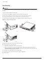
Installing the Switch
Rack Mounting
Removing the Switch from a Rack
Free-Standing
Desktop Mounting of Multiple Switches
65
66
67
67
67
Installing or Replacing a Mini-Gigabit Interface Connector (Mini-GBIC)
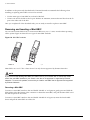
Removing and Inserting a Mini-GBIC
67
68
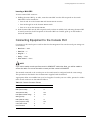
Connecting Equipment to the Console Port
69
Powering On the SwitchSummit 300-48 switch
70
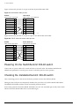
Checking the InstallationSummit 300-48 switch
70
Logging In for the First Time
71
Accessory Installation
Summit 300 Optional Features
External Power Supply (45019)
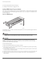
Rack-mounting the EPS-LD unit
Connecting the EPS-LD unit
Removing an EPS-LD unit
75
76
77
79
Internal 600 Watt Power Supply (15412)
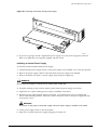
Removing and Installing Summit 300-48 Power Supplies
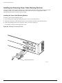
Installing and Removing Power Cable Retaining Brackets
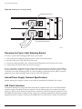
Removing the Power Cable Retaining Bracket
79
80
82
84
Consolidated "e" Series Hardware Installation Guide
5
Internal Power Supply Technical Specifications
LED Visual Indicators
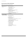
Environmental and Safety Specifications
Chapter 8
Summit 400-48t Optional Features
Installing Optional Features
Installing the Summit XEN Card
Installing the External Power System
Rack Mounting the EPS-T
Adding a second EPS-160 to the EPS-T
Removing an EPS-160 from the EPS-T
Part 5
Appendix A
89
89
91
92
94
95
Appendixes
Safety Information
Important Safety Information
Power
Power Cable
Optical Safety
Lithium Battery
Appendix B
84
84
86
99
99
100
100
101
“e” Series Technical Specifications
Common Switch Specifications
103
Summit 200 Series Switch Specifications
105
Summit 300 Series Switch Specifications
106
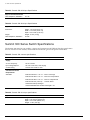
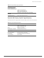
Summit 400 Series Switch Specifications
107
Index
6
Consolidated "e" Series Hardware Installation Guide
Preface
This preface provides an overview of this guide, describes guide conventions, and lists other
publications that might be useful.
NOTE
To ensure proper operation of your Extreme Networks equipment, read this guide before you install any
Extreme Networks equipment.
Introduction
This guide provides the required information to install an Extreme Networks® Summit™ switch. It also
contains information about site location, switch functionality, and switch operation.
This guide is intended for use by network administrators who are responsible for installing and setting
up network equipment. It assumes a basic working knowledge of:
• Local Area Networks (LANs)
• Ethernet concepts
• Ethernet switching and bridging concepts
• Routing concepts
• Simple Network Management Protocol (SNMP)
See the ExtremeWare Software User Guide for information about configuring an Extreme Networks switch.
NOTE
If the information in the Release Notes that shipped with your switch differs from the information in this
guide, follow the Release Notes.
Consolidated "e" Series Hardware Installation Guide
7
Preface
Conventions
Table 1 and Table 2 list conventions used throughout this guide.
Table 1: Notice icons
Icon
Notice Type
Alerts you to...
Note
Important features or instructions.
Caution
Risk of personal injury, system damage,
or loss of data.
Warning
Risk of severe personal injury.
Table 2: Text conventions
Convention
Description
Screen displays
This typeface represents information as it appears on the screen,
or command syntax.
Screen displays bold
This typeface represents commands that you type.
The words “enter”
and “type”
When you see the word “enter” in this guide, you must type
something, and then press the Return or Enter key. Do not press
the Return or Enter key when an instruction simply says “type.”
[Key] names
Key names appear in text in one of two ways:
•
Referenced by their labels, such as “the Return key” or “the
Escape key”
•
Written with brackets, such as [Return] or [Esc]
If you must press two or more keys simultaneously, the key names
are linked with a plus sign (+). Example:
Press [Ctrl]+[Alt]+[Del].
Words in italicized type
Italics emphasize a point of information or denote new terms at the
place where they are defined in the text.
Related Publications
The Extreme Networks switch documentation set includes:
• Consolidated “e” Series Hardware Installation Guide (this guide)
• ExtremeWare Software User Guide
• ExtremeWare Software Command Reference Guide
• ExtremeWare Release Notes
8
Consolidated "e" Series Hardware Installation Guide
About This Guide
Documentation for Extreme Networks products is available from the Extreme Networks website at the
following location:
http://www.extremenetworks.com/services/documentation/
You can select and download the following Extreme Networks documentation from the Documentation
section of the Services page:
• Release Notes (you must have a valid service contract to access the release notes)
• Software User Guides
• Hardware User Guides
• White Papers
• Troubleshooting Tools
• Preventative Maintenance
• Instructional Videos
• Archives
About This Guide
This guide describes how to prepare your site and how to install, maintain, and operate your Extreme
Networks switch. It contains information on features that are common to all switches, as well as
switch-specific features. This guide contains six parts:
• Preparing for Installation—Describes the “e” series of Summit switches. This section introduces the
Summit 200, Summit 300 and Summit 400 models that comprise the “e” series. It also describes how
to evaluate, plan, and determine the best location for your Extreme Networks switch.
• Switch Overview—Describes the physical characteristics of each of the “e” series, including the front
view, rear view, and LED behaviors.
• Switch Installation—Describes the installation process that is shared by the “e” series of Summit
switches. This section describes rack installation, mini-GBIC installation, connecting to the console
port and installation verification. It also includes the procedure for logging into the switch for the
first time.
• Accessory Installation:
— Summit 200—Describes the optional features and their installation that are specific to the
Summit 200 switch.
— Summit 300—Describes the optional features and their installation that are specific to the
Summit 300 switch.
— Summit 400—Describes the optional features and their installation that are specific to the
Summit 400-48t switch.
• Appendixes—Describes safety requirements and technical specifications.
How To Use This Guide
Each chapter of this guide contains information on how to successfully operate your Extreme Networks
switch. The model-specific chapters contain information that is applicable to that Summit switch only.
All other chapters are applicable to any Extreme Networks switch.
Consolidated "e" Series Hardware Installation Guide
9
Preface
Switch-Specific Information
For switch-specific information, be sure to read the applicable model-specific chapter. For example, if
you have a Summit 400-48t switch and you need to set up a combination port, “Uplink Redundancy”
on page 61 for specific details for cabling combination ports.
Common Information
For items applicable to any Extreme Networks switch, make sure you read the appropriate chapter. For
example, to learn how to prepare your site for installing your Extreme Networks equipment, see
Chapter 2, “Site Preparation.”
This guide also contains appendices that describe:
• Switch safety issues
• Switch specifications
Appendix A, “Safety Information” describes important safety issues such as power, power cables, and
fuses.
Appendix B, ““e” Series Technical Specifications” is organized according to the model of Summit
switch. This appendix describes switch specifications such as physical dimensions, weight, certifications,
and power supply parameters.
Information that is common to all switches is described at the beginning of the appendix.
10
Consolidated "e" Series Hardware Installation Guide
Part 1
Preparing for Installation
1
Overview of the “e” Series of Switches
This chapter describes:
• Summit “e” Series and Models on page 13
• Port Connections on page 18
• Following Safety Information on page 18 on page 18
• Software Images on page 19
• Full-Duplex Support on page 19
Summit “e” Series and Models
This installation manual supports the Summit models that comprise the “e” series:
• The Summit 200 models:
— Summit 200-24 switch
— Summit 200-48 switch
• The Summit 300 Power over Ethernet (PoE) models:
— Summit 300-24 switch
— Summit 300-48 switch
• The Summit 400-48t switch
For installation information on other Summit switches, refer to the Extreme Networks Consolidated “i”
Series Hardware Installation Guide.
Summit 200 Features
This section summarizes the hardware and software features of the Summit 200. See “Summit 200 Series
Switch Overview” on page 41 for details of the front panel, rear panel, and LEDs.
Hardware Features
The Summit 200-24 switch is a compact enclosure with the following features:
• One rack unit in height (1.75 inches or 44.45 mm)
Consolidated "e" Series Hardware Installation Guide
13
Overview of the “e” Series of Switches
• 24 autosensing 10BASE-T/100BASE-TX ports using RJ-45 connectors
• Two 10/100/1000BASE-T Gigabit Ethernet uplink ports using RJ-45 connectors
• Two optical ports that allow Gigabit Ethernet uplink connections through Extreme 1000BASE-SX,
1000BASE-LX, or 1000BASE-ZX Small Form Factor pluggable (SFP) Gigabit Interface Connectors
(GBICs)—also known as mini-GBICs—using LC optical fiber connectors. Mini-GBICs are purchased
separately, for more information contact your Extreme Networks Sales Representative.
Software Features
This section describes the features of the different Summit series. If the information in the release notes
differs from the information in this guide, follow the release notes. For more information about
configuring the switch, refer to the ExtremeWare Software User Guide and The ExtremeWare Command
Reference Guide.
The Summit 200 series switches support the following ExtremeWare features:
• Virtual local area networks (VLANs) including support for IEEE 802.1Q and IEEE 802.1p
• Spanning Tree Protocol (STP) (IEEE 802.1D)
• Rapid Spanning Tree Protocol (IEEE 802.1W)
• Quality of Service (QoS) including support for IEEE 802.1p, MAC QoS, and four hardware queues
• Wire-speed Internet Protocol (IP) routing
• DHCP/BOOTP Relay
• Network Address Translation (NAT)
• Extreme Standby Router Protocol (ESRP)
• Ethernet Automated Protection Switching (EAPS) support (RFC 3619)
• Simple Network Time Protocol (SNTP)
• Protocol Multicast-Sparse Mode (PIM-SM)
• Virtual Router Redundancy Protocol (VRRP)
• Routing Information Protocol (RIP) version 1 and RIP version 2
• Open Shortest Path First (OSPF) routing protocol
• DiffServ support
• Access-policy support for routing protocols
• Access list support for packet filtering
• Access list support for rate-limiting
• IGMP snooping to control IP multicast traffic
• Load sharing on multiple ports
• Dynamic load sharing on multiple ports
• RADIUS client and per-command authentication support
• TACACS+ support
• Network login
• Console command-line interface (CLI) connection
• Telnet CLI connection
• SSH2 connection
14
Consolidated "e" Series Hardware Installation Guide
Summit “e” Series and Models
• Simple Network Management Protocol (SNMP) support
• Remote Monitoring (RMON)
• Traffic mirroring for ports
Summit 300 Features
This section summarizes the hardware and software features of the Summit 300. See “Summit 300
Switch Overview” on page 47 for details of the front panel, rear panel, and LEDs.
Hardware Features
The Summit 300-48 supports the following features:
• Unified Access support
• 2 rack units in height
• 4 Gigabit Ethernet uplinks, fiber/UTP redundant
• Supports up to 48 10/100 Ethernet ports
• Modular expansion slot supports various port configurations
• Serial management port
• Redundant hot swappable power supply
Software Features
Unified Access. The Summit 300 supports the Unified Access architecture, enabling wired and
wireless applications across a completely integrated enterprise infrastructure. With the Altitude product
line, the Summit 300 supports 802.11 WLAN connectivity. Provisioning of Unified Access is completely
controlled by the Summit 300.
Other software features of the Summit 300 include:
• Virtual local area networks (VLANs) including support for IEEE 802.1Q and IEEE 802.1p
• VLAN aggregation
• Spanning Tree Protocol (STP) (IEEE 802.1D)
• Rapid Spanning Tree Protocol (IEEE 802.1W)
• Quality of Service (QoS) including support for IEEE 802.1P, MAC QoS, and eight hardware queues
• Policy-Based Quality of Service (PB-QoS)
• Wire-speed Internet Protocol (IP) routing
• Extreme Standby Router Protocol (ESRP) - Aware support
• Ethernet Automated Protection Switching (EAPS) support (RFC 3619)
• Simple Network Time Protocol (SNTP)
• Jumbo frame support
• DHCP/BOOTP Relay
• Routing Information Protocol (RIP) version 1 and RIP version 2
• Open Shortest Path First (OSPF) routing protocol
Consolidated "e" Series Hardware Installation Guide
15
Overview of the “e” Series of Switches
• Wire-speed IP multicast routing support
• Diffserv support
• Access-policy support for routing protocols
• Access list support for packet filtering
• Access list support for rate-limiting
• IGMP snooping to control IP multicast traffic
• Protocol Independent Multicast-Sparse Mode (PIM-SM)
• Load sharing on multiple ports
• Dynamic load sharing on multiple ports
• RADIUS client and per-command authentication support
• TACACS+ support
• Console command line interface (CLI) connection
• Telnet CLI connection
• SSH2 connection
• ExtremeWare Vista Web-based management interface
• Simple Network Management Protocol (SNMP) support
• Remote Monitoring (RMON)
• Traffic mirroring for ports by port number
• Network Login—Web
• Network Login—IEEE 802.1X
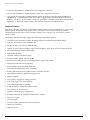
Summit 400 Features
This section summarizes the hardware and software features of the Summit 400-48t. See “Summit
400-48t Switch Overview” on page 57 for details of the front panel, rear panel, and LEDs.
Hardware Features
The Summit 400 series switch supports the following ExtremeWare features:
• 48 copper ports 10/100/1000BASE-T
• 4 fiber SFP (mini-GBIC 1000BASE-SX, 1000BASE-LX, and 1000BASE-ZX)
The fiber ports share PHY with the first four copper port.
• 1 copper management port 10/100/1000BASE-T
• 1 console port, serial
• 2 (optional) modular 10 Gigabit uplink ports
• 2 stacking ports (10 Gigabit) reserved for future software features
• Supports redundant power support using the optional EPS 160 External Power Supply
• Redundant uplink support
16
Consolidated "e" Series Hardware Installation Guide
Summit “e” Series and Models
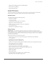
Software Features
The software features of the Summit 400-48t include:
• Virtual local area networks (VLANs) including support for IEEE 802.1Q and IEEE 802.1p
• VLAN aggregation
• Spanning Tree Protocol (STP) (IEEE 802.1D)
• Rapid Spanning Tree Protocol (IEEE 802.1W)
• Quality of Service (QoS) including support for IEEE 802.1P, MAC QoS, and eight hardware queues
• Policy-Based Quality of Service (PB-QoS)
• Wire-speed Internet Protocol (IP) routing
• Extreme Standby Router Protocol (ESRP)
• Virtual Router Redundancy Protocol (VRRP)
• Ethernet Automated Protection Switching (EAPS) support (RFC 3619)
• Simple Network Time Protocol (SNTP)
• Jumbo frame support
• DHCP/BOOTP Relay
• Routing Information Protocol (RIP) version 1 and RIP version 2
• Open Shortest Path First (OSPF) routing protocol
• Wire-speed IP multicast routing support
• Diffserv support
• Access-policy support for routing protocols
• Access list support for packet filtering
• Access list support for rate-limiting
• IGMP snooping to control IP multicast traffic
• Protocol Independent Multicast-Sparse Mode (PIM-SM)
• Load sharing on multiple ports
• Dynamic load sharing on multiple ports
• RADIUS client and per-command authentication support
• TACACS+ support
• Console command line interface (CLI) connection
• Telnet CLI connection
• SSH2 connection
• ExtremeWare Vista Web-based management interface
• Simple Network Management Protocol (SNMP) support
• Remote Monitoring (RMON)
• Traffic mirroring for ports by port number
• Network Login—Web
• Network Login—IEEE 802.1X
Consolidated "e" Series Hardware Installation Guide
17
Overview of the “e” Series of Switches
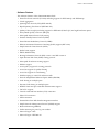
Port Connections
Extreme “e” switches use a combination of the following types of ports:
• Small Form Factor Pluggable (SFP) Gigabit Interface Connectors (GBICs), also known as mini-GBICs:
— 1000BASE-SX ports (850 nm optical window) using LC connectors
— 1000BASE-LX ports (1310 nm optical window) using LC connectors
— 1000BASE-ZX ports (1550 nm optical window) using LC connectors
• 10/100/1000BASE-T Gigabit Ethernet ports using RJ-45 connectors
• 10BASE-T/100BASE-TX ports using RJ-45 connectors
Table 1 describes port configurations available on the different “e” switch models.
Table 1: Port configurations on all “e” switch models
Switch Model
10/100/
1000
BASE-T
GBIC
Summit 200-24
2
2
Summit 200-48
2
2
Summit 300-24
2
2
2
24
Summit 300-48
2
4
4
48
Summit 400-48t
48
4
4
Ethernet Ports
Combo Ports
10BASE-T/
100BASETX
24
48
Further details on ports can be found:
• “Evaluating and Meeting Mini-GBIC Requirements” on page 31
• “Port Connections” on page 44 for Summit 200
• “Summit 300-48 switchConsole Port” on page 49 for Summit 300
• “Port Connections” on page 61 for Summit 400
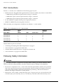
Following Safety Information
WARNING!
Read the safety information in Appendix A thoroughly before installing your Extreme Networks switch.
Failure to follow this safety information can lead to personal injury or damage to the equipment.
• All service to components of an “e” series switch should be performed by trained service personnel
only. Service personnel are persons having appropriate technical training and experience necessary
to be aware of the hazards to which they are exposed in performing a task and of measures to
minimize the danger to themselves or other persons.
• Some devices, such as GBICs, contain fiber optic ports. To protect your eyes, you should never look
at the fiber optic ports while they are on, or look directly at the fiber cable ends when they are on.
18
Consolidated "e" Series Hardware Installation Guide
Software Images
Software Images
When you receive a new Extreme Networks switch, be aware that an the ExtremeWare® software image
and a BootROM image has been pre installed at the factory. To verify the software image you are
running on your switch, use the show version command. The show version command displays the
hardware and software versions currently running on the switch. To ensure that you have the latest
software and BootROM image, go to the support login portion of the Tech Support page at:
http://www.extremenetworks.com/services/
NOTE
If the information in the Release Notes that shipped with your switch differs from the information in this
guide, follow the Release Notes.
Full-Duplex Support
Extreme Networks switches provide full-duplex support for all ports. This means that frames can be
transmitted and received simultaneously, which, in effect, doubles the bandwidth that is available on a
link. Most ports on an Extreme Networks switch autonegotiate for half-duplex or full-duplex operation.
Gigabit Ethernet and 100BASE-FX ports operate in full-duplex mode only in accordance with technical
standards.
Consolidated "e" Series Hardware Installation Guide
19
Overview of the “e” Series of Switches
20
Consolidated "e" Series Hardware Installation Guide
2
Site Preparation
This chapter describes how to prepare your site for installing Extreme Networks equipment. It contains
information on environmental and cabling requirements, power requirements, and building and
electrical code organizations.
This chapter includes these sections:
• Planning Your Site on page 22
• Meeting Site Requirements on page 22
• Evaluating and Meeting Cable Requirements on page 27
• Meeting Power Requirements on page 34
• Applicable Industry Standards on page 37
The requirements described in this chapter are intended for the system administrator, network
equipment technician, or network manager who is responsible for installing and managing the network
hardware. It assumes a working knowledge of local area network (LAN) operations, and a familiarity
with communications protocols that are used on interconnected LANs. Installation, maintenance, and
removal of a switch, chassis, or its components must be done by qualified service personnel only.
Qualified service personnel have had appropriate technical training and experience that is necessary to
be aware of the hazards to which they are exposed when performing a task and of measures to
minimize the danger to themselves or other people.
By carefully planning your site, you can maximize the performance of your existing network and ensure
that it is ready to migrate to future networking technologies.
To learn more about safety issues and to ensure safety compliance, see Appendix A.
WARNING!
Read the safety information in Appendix A thoroughly before installing your Extreme Networks switch.
Failure to follow this safety information can lead to personal injury or damage to the equipment.
Consolidated "e" Series Hardware Installation Guide
21
Site Preparation
Planning Your Site
To install your equipment successfully, you should plan your site carefully. The site planning process
has three major steps:
Step 1: Meeting Site Requirements
Your physical installation site must meet several requirements for a safe and successful installation:
• Building and electrical code requirements
• Environmental, safety, and thermal requirements for the equipment you plan to install
• Distribution rack requirements
Step 2: Evaluating and Meeting Cable Requirements
After examining your physical site and ensuring all environment requirements are met, you should
evaluate and compare your existing cable plant with the requirements of the Extreme Networks
equipment to determine if you need to install new cables (or cabling).
Step 3: Evaluating and Meeting Mini-GBIC Requirements
After you have established your fiber cable requirements, you should ensure that your mini-GBICs
support the distance and media types you are planning to install.
Step 4: Meeting Power Requirements
To run your equipment safely, you must meet the specific power requirements for the Extreme
Networks equipment that you plan to install.
NOTE
Review and follow the safety information before you install your equipment.
Meeting Site Requirements
This section addresses the various requirements to consider when preparing your installation site,
including:
• Operating Environment Requirements
• Rack Specifications and Recommendations
Operating Environment Requirements
You need to verify that your site meets all environmental and safety requirements.
Virtually all areas of the United States are regulated by building codes and standards. During the early
planning stages of installing or modifying your LAN, it is important that you develop a thorough
understanding of the regulations that pertain to your location and industry.
22
Consolidated "e" Series Hardware Installation Guide
Meeting Site Requirements
Building and Electrical Codes
Building and electrical codes vary depending on your location. Comply with all code specifications
when planning your site and installing cable. The following sections are provided as a resource to
obtain additional information.
Three major building codes are:
• Uniform Building Code—produced by the International Conference of Building Officials (ICBO);
5360 South Workman Mill Road; Whittier, California 90601 USA. www.icbo.org
• BOCA Basic Building Code—produced by the Building Officials and Code Administrators (BOCA)
International, Inc.; 4051 West Flossmoor Road; Country Club Hills, Illinois 60478 USA.
www.bocai.org
• Standard Building Code (SBC)—produced by the Southern Building Code Congress International,
Inc.; 900 Montclair Road; Birmingham, Alabama 35213 USA. www.sbcci.org
Five authorities on electrical codes are:
• National Electrical Code (NEC) Classification (USA only)—a recognized authority on safe electrical
wiring. Federal, state, and local governments use NEC standards to establish their own laws,
ordinances, and codes on wiring specifications. The NEC classification is published by the National
Fire Protection Association (NFPA). The address is NFPA; 1 Batterymarch Park; Quincy,
Massachusetts 02269 USA. www.nfpa.org
• Underwriters’ Laboratory (UL) (USA only)—an independent research and testing laboratory. UL
evaluates the performance and capability of electrical wiring and equipment to determine whether
they meet certain safety standards when properly used. Acceptance is usually indicated by the
words “UL Approved” or “UL Listed.” The address is UL; 333 Pfingsten Road; Northbrook, Illinois
60062-2096 USA. www.ul.com
• National Electrical Manufacturing Association (NEMA) (USA only)—an organization of electrical
product manufacturers. Members develop consensus standards for cables, wiring, and electrical
components. The address is NEMA; 2101 L Street N.W.; Washington, D.C. 20037 USA.
www.nema.org
• Electronics Industry Association (EIA)—a trade association that develops technical standards,
disseminates marketing data, and maintains contact with government agencies in matters relating to
the electronics industry. The address is EIA; 2001 Eye Street N.W.; Washington, D.C. 20006 USA.
www.eia.org
• Federal Communications Commission (FCC)—a commission that regulates all interstate and foreign
electrical communication systems that originate in the United States according to the
Communications Act of 1934. The FCC regulates all U.S. telephone and cable systems. The address is
FCC; 1919 M Street N.W.; Washington, D.C. 20554 USA.
Wiring Closet Considerations
You should consider the following recommendations for your wiring closet:
• Ensure that your system is easily accessible for installation and service. See “Rack Specifications and
Recommendations” on page 25 for specific recommendations.
• Use appropriate AC power for your switch, as described in Table 2.
Table 2: AC power requirements
Country
Requirements
North America
13 A service receptacle, NEMA 5-15 for 110/220 VAC power supplies.
Consolidated "e" Series Hardware Installation Guide
23
Site Preparation
Table 2: AC power requirements (continued)
Country
Requirements
United Kingdom
10 A service receptacle, BS 1363 for 110/220 VAC power supplies.
International
10 A service receptacle, CEE 7/7 for 110/220 VAC power supplies.
Australia
10 A service receptacle, AS 3112 for 110/220 VAC power supplies.
Japan
15 A service receptacle, JIS 8303 for 110/220 VAC power supplies.
• Use a vinyl floor covering in your wiring closet. (Concrete floors accumulate dust, and carpets can
cause static electricity.)
• Prevent unauthorized access to wiring closets by providing door locks. Install the equipment in a
secured, enclosed, and restricted-access area, ensuring that only qualified service personnel have
access to the equipment.
• Provide adequate overhead lighting for easy maintenance.
• Ensure that each wiring closet has a suitable ground. All distribution racks and equipment installed
in the closet should be grounded.
• Ensure that all system environmental requirements are met, such as ambient temperature and
humidity.
NOTE
Extreme Networks recommends that you consult an electrical contractor for commercial building and
wiring specifications.
Temperature. Extreme Networks equipment generates a significant amount of heat. It is essential that
you provide a temperature-controlled environment for both performance and safety.
Install the equipment only in a temperature- and humidity-controlled indoor area that is free of airborne
materials that can conduct electricity. Too much humidity can cause a fire. Too little humidity can
produce electrical shock and fire.
The following are some general thermal recommendations for your wiring closet:
• Ensure that the ventilation in the wiring closet is adequate to maintain a temperature below 104° F
(40° C).
• Install a reliable air conditioning and ventilation system.
• Keep the ventilation in the wiring closet running during nonbusiness hours; otherwise, the
equipment can overheat.
• Maintain ambient operating temperature: 32° to 104° F (0° to 40° C)
• Maintain storage Temperature: -40° to 158° F (-40° to 70° C)
NOTE
Like all electrical equipment, product lifetimes degrade with increased temperature. If possible,
temperatures should be kept at approximately 78° F (25° C) or lower.
Airflow Requirements. To ensure proper airflow through an Extreme Networks switch, refer to the
following recommendations when you are installing your switch:
24
Consolidated "e" Series Hardware Installation Guide
Meeting Site Requirements
The “e” series of switches require 3 inches (7.62 cm) on both the left and right sides of the switch (5
inches (12.7 cm) recommended) for proper airflow.
The airflow of the “e” series of switches moves from the left side of the switch to the right side of the
switch, or from the right side of the switch to the left side of the switch depending on the model.
Humidity. Operating humidity should be kept between 10 and 95% relative humidity (noncondensing).
Rack Specifications and Recommendations
Racks should conform to conventional standards. In the United States, use EIA Standard RS-310C:
Racks, Panels, and Associated Equipment. In countries other than the United States, use IEC Standard
297. In addition, verify that your rack meets the basic mechanical and space requirements that are
described in this section.
Mechanical Recommendations for the Rack
Use distribution racks that meet the following mechanical recommendations:
• Use an open style, 19-inch (48.26 cm) rack to facilitate easy maintenance and to provide proper
ventilation.
• The rack should use the universal mounting rail hole pattern that is identified in IEC Standard 297.
• The mounting holes should be flush with the rails to accommodate the chassis.
• Use a rack made of steel or aluminum.
• Install equipment into the lower half of the rack first to avoid making the rack top-heavy.
• The rack should support approximately 600 pounds (272 kilograms).
Protective Grounding for the Rack
Use a rack grounding kit and a ground conductor that is carried back to earth or to another suitable
building ground.
All Extreme Networks switches are designed with mounting brackets that provide solid metal-to-metal
connection to the rack. If you do not use equipment racks, you can attach wiring terminals directly to
the mounting brackets for appropriate grounding. Alpine products have grounding terminals that are
mounted on the back of the chassis.
At minimum, follow these guidelines:
• Ground equipment racks to earth ground.
— CAD weld appropriate wire terminals to building I-beams or earth ground rods.
— Use #4 copper wire.
— Drill and tap wire terminals to equipment racks.
— Position the earth ground as close to the equipment rack as possible to maintain the shortest
wiring distance possible.
— Properly test the quality of the earth ground.
Consolidated "e" Series Hardware Installation Guide
25
Site Preparation
NOTE
Because building codes vary worldwide, Extreme Networks strongly recommends that you consult an
electrical contractor to ensure proper equipment grounding is in place for your specific installation.
• Ground DC power supplies to earth ground by using the grounding terminals provided.
Space Requirements for the Rack
Provide enough space in front of and behind the switch so that you can service it easily. Allow a
minimum of 48 inches (122 cm) in front of the rack and 24 inches (61 cm) behind the rack. When using a
relay rack, provide a minimum of 24 inches (61 cm) of space behind the mounted equipment. Extra
room on each side is optional.
NOTE
Install your equipment rack near an easily accessible power outlet. When you need to disconnect the
power cable from your switch, remove it first from the power source and then from the switch.
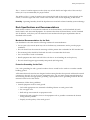
Securing the Rack
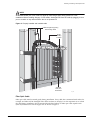
The rack should be attached to the wiring closet floor with 3/8 inch (9.5 mm) lag screws or equivalent
hardware. The floor under the rack should be level within 3/16 inch
(5 mm). Use a floor-leveling cement compound if necessary or bolt the racks to the floor as shown in
Figure 1.
26
Consolidated "e" Series Hardware Installation Guide
Evaluating and Meeting Cable Requirements
Figure 1: Properly secured rack (SPG_007 redraw with e series in the rack)
Secure to floor
with 3/8 inch lag screws or bolts
SPG_007
Brace open distribution racks if the channel thickness is less than 1/4 inch (6.4 mm).
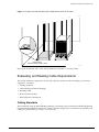
Evaluating and Meeting Cable Requirements
This section addresses requirements for the that cable you should use when installing your network
equipment. It includes:
• Cabling Standards
• Cable Labeling and Record Keeping
• Installing Cable
• RJ-45 Connector Jackets
• Radio Frequency Interference
Cabling Standards
We recommend using the BICSI (Building Industry Consulting Service International) RCDD (Registered
Communications Distribution Designer), which is globally recognized as a standard in site planning and
cabling. For information, go to http://www.bicsi.org
Consolidated "e" Series Hardware Installation Guide
27
Site Preparation
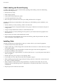
Cable Labeling and Record Keeping
A reliable cable labeling system is essential when planning and installing a network. Maintaining
accurate records helps you to:
• Relocate devices easily.
• Make changes quickly.
• Isolate faults in the distribution system.
• Locate the opposite end of any cable.
• Know the types of network devices that your cabling infrastructure can support.
Consider the following recommendations when setting up a cable labeling system suitable for your
installation:
• Identify cables by securely attaching a label to all cable ends.
• Assign a unique block of sequential numbers to the group of cables that run between each pair of
wiring closets.
• Assign a unique identification number to each distribution rack.
• Identify all wiring closets by labeling the front panel of your Extreme Networks equipment and
other hardware.
• Keep accurate and current cable identification records.
• Post records near each distribution rack. Include the following cable drop information: the cable
source, destination, and jumper location.
Installing Cable
Consider the following recommendations when you connect cable to your network equipment:
• Examine cable for cuts, bends, and nicks.
• Support cable using a cable manager that is mounted above connectors to avoid unnecessary weight
on the cable bundles.
• Use cable managers to route cable bundles to the left and right of the network equipment to
maximize accessibility to the connectors.
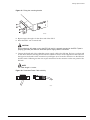
• Provide enough slack—approximately 2 to 3 inches (5.08-7.62 cm)— to provide proper strain relief as
shown in Figure 2.
• Bundle cable using velcro straps to avoid injuring cables.
• If you build your own cable, ensure that cable is properly crimped.
• When installing a patch panel using twisted pair wiring, untwist no more than 1 inch (2.54 cm) of
the cable to avoid RF interference.
• When required for safety and fire rating requirements, use plenum-rated cable. See your local
building codes for determining when it is appropriate to use plenum-rated cable, or refer to IEC
standard 850.
• Keep all ports and connectors free of dust.
28
Consolidated "e" Series Hardware Installation Guide
Evaluating and Meeting Cable Requirements
NOTE
Unshielded twisted pair (UTP) cable can build up ESD charges when being pulled into a new
installation. Before installing category 5 UTP cables, discharge ESD from the cable by plugging it into a
port on a switch or any network device that is not powered on.
Figure 2: Properly installed and bundled cable
Cable managers supporting
and directing cables
Proper
bundling
of cables
Adequate
slack, and
bend radius
SPG_008
Fiber Optic Cable
Fiber optic cable must be treated gently during installation. Every cable has a minimum bend radius, for
example, and fibers will be damaged if the cables are bent too sharply. It is also important not to stretch
the cable during installation. We recommend that the bend radius for fiber optic cable equals 2-inch
(5.08 cm) minimum for each 90 degree turn as shown in Figure 3.
Consolidated "e" Series Hardware Installation Guide
29
Site Preparation
NOTE
Kinks and sharp bends can destroy or impair the cable’s ability to convey light pulses accurately from
one end of the cable to the other. Use care in dressing the optical-fiber cables: provide satisfactory
strain relief to support the cable and maintain an adequate bend radius at all cable turns, particularly
where the cable connects to the I/O module.
Figure 3: Bend radius for fiber optic cable
Minimum
2 in. (5.08cm)
radius
in 90˚ bend
90˚
Optical fiber cable
SPG_002
Cable Distances
Table 3 shows cable media types and maximum distances that support reliable transmission in
accordance with international standards except where noted.
Table 3: Media types and maximum distances
Standard
Media Type
Mhz•Km
Rating
Maximum Distance
(Meters)
1000BASE-SX
(850 nm optical
window)
50/125 µm multimode fiber
400
500
50/125 µm multimode fiber
500
550
62.5/125 µm multimode fiber
160
220
62.5/125 µm multimode fiber
200
275
50/125 µm multimode fiber
400
550
50/125 µm multimode fiber
500
550
62.5/125 µm multimode fiber
500
550
10/125 µm single-mode fiber
—
5,000
1000BASE-ZX
(1550 nm optical
window)
10/125 µm single-mode fiber
—
50,000
1000BASE-T
Category 5 and higher UTP cable
–
100
100BASE-TX
Category 5 and higher UTP cable
–
100
10BASE-T
Category 3 and higher UTP cable
–
100
1000BASE-LX
(1310 nm optical
window)
30
Consolidated "e" Series Hardware Installation Guide
Evaluating and Meeting Mini-GBIC Requirements
Evaluating and Meeting Mini-GBIC Requirements
All “e” series switches support the small form pluggable (SFP) GBIC, also known as the mini-GBIC. The
switches identify the type of mini-GBIC that is installed and verifies that the mini-GBIC is an Extreme
Networks-certified mini-GBIC.
Mini-GBIC Types and Specifications
There are three types of mini-GBIC interfaces:
• SX mini-GBIC, which conforms to the 1000BASE-SX standard
• LX mini-GBIC, which conforms to the 1000BASE-LX standard
• ZX mini-GBIC, which conforms to the IEEE 802.3z standard
Use only Extreme Networks-certified mini-GBICs, available from Extreme Networks, in the mini-GBIC
port in the switch or module. See Table 3 on page 30 for the media type and maximum distances that
support mini-GBICs.
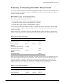
Table 4 describes the specifications for the SX mini-GBIC interface, Table 5 describes the specifications
for the LX mini-GBIC interface, and Table 6 describes the specifications for the ZX mini-GBIC interface.
Table 4: SX mini-GBIC specifications
Parameter
Minimum
Typical
Maximum
Transceiver
Optical output power
-9.5 dBm
Center wavelength
830 nm
-4 dBm
850 nm
860 nm
Receiver
Optical input power sensitivity
-21 dBm
Optical input power maximum
Operating wavelength
-4 dBm
830 nm
860 nm
General
Total system budget
11.5 dB
Total optical system budget for the SX mini-GBIC is 11.5 dB. Extreme Networks recommends that 3 dB
of the total budget be reserved for losses induced by cable splices/connectors and operating margin.
While 8.5 dB remains available for cable induced attenuation, the 1000BASE-SX standard specifies
supported distances of 275 meters over 62.5 micron multimode fiber and 550 meters over 50 micron
multimode fiber. There is no minimum attenuation or minimum cable length restriction.
Table 5: LX mini-GBIC specifications
Parameter
Minimum
Typical
Maximum
Transceiver
Optical output power
-9.5 dBm
Center wavelength
1275 nm
Consolidated "e" Series Hardware Installation Guide
-3 dBm
1310 nm
1355 nm
31
Site Preparation
Table 5: LX mini-GBIC specifications (continued)
Parameter
Minimum
Typical
Maximum
Receiver
Optical input power sensitivity
-23 dBm
Optical input power maximum
Operating wavelength
-3 dBm
1270 nm
1355 nm
General
Total system budget
13.5 dB
Total optical system budget for the LX mini-GBIC is 13.5 dB. Measure cable plant losses with a 1310 nm
light source and verify this to be within budget. When calculating the maximum distance attainable
using optical cable with a specified loss per kilometer (for example 0.25 dB/km) Extreme Networks
recommends that 3 dBm of the total budget be reserved for losses induced by cable splices/connectors
and operating margin. Thus, 10.5 dB remains available for cable induced attenuation. There is no
minimum system budget or minimum cable length restriction because the maximum receive power is
the same as the maximum transmit power. There is no minimum attenuation or minimum cable length
restriction.
Table 6: ZX mini-GBIC specifications
Parameter
Minimum
Typical
Maximum
Optical output power
-2 dBm
0 dBm
3 dBm
Center wavelength
1540 nm
1550 nm
1570 nm
Transceiver
Receiver
Optical input power sensitivity
-23 dBm
Optical input power maximum
Operating wavelength
-3 dBm
1540 nm
1550 nm
1570 nm
The ZX mini-GBIC is compatible with and interoperates with long range GBICs. For more information
about the budget requirements and minimum attenutation requirements of long range GBICs, see “Long
Range Mini-GBIC System Budgets”.
Long Range Mini-GBIC System Budgets
Measure cable plant loses with a 1550 nm light source and verify this to be within budge. When
calculating the maximum distance attainable suing optical cable with a specified loss per kilometer (for
example 0.25 dB/km), Extreme Networks recommends that 3 dB of the total budget be reserved for
32
Consolidated "e" Series Hardware Installation Guide
Evaluating and Meeting Mini-GBIC Requirements
loses induced by cable splices, connectors, and operating margin. Table 7 lists the minimum
attenuations that are required by each long range mini-GBIC to prevent saturation of the receiver.
Table 7: Minimum attenuation requirements
Receivers
Transceivers
GBIC Type
LX70
LX100
ZX (prior to
Rev 03)
ZX Rev 03
ZX mini
LX70
9 dB
13 dB
7 dB
7 dB
9 dB
LX100
8 dB
12 dB
6 dB
6 dB
8 dB
ZX (prior to
Rev 03)
2 dB
6 dB
0 dB
0 dB
2 dB
ZX Rev 03
5 dB
9 dB
3 dB
3 dB
5 dB
ZX mini
6 dB
10 dB
4 dB
4 dB
6 dB
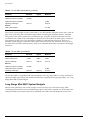
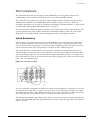
RJ-45 Connector Jackets
Use RJ-45 cable with connector jackets that are flush with the connector or that have connectors with a
no-snag feature.
Using cable with jackets that are wider than the connectors can cause:
• Connectors that are not properly aligned with the port.
• Crowded cable installation, which can cause connectors to pop out of the port.
Figure 4 shows examples of connector jacket types that are not recommended as well as those that are
recommended.
Figure 4: RJ-45 connector jacket types
Not recommended
Best
Better
Consolidated "e" Series Hardware Installation Guide
0.1" = 1mm actual
39.37% : 254%
SPG_001
33
Site Preparation
Radio Frequency Interference
If you use unshielded twisted pair (UTP) cabling in an installation, take precautions to avoid radio
frequency (RF) interference. RF interference can cause degradation of signal quality, and, in an Ethernet
network environment, can cause excessive collisions, loss of link status, or other physical layer problems
that can lead to poor performance or loss of communication.
To prevent RF interference, avoid the following devices or situations:
• Attaching UTP cable to AC power cables
• Routing UTP cable near antennas, such as a Ham radio antenna
• Routing UTP cable near equipment that could exhibit RF interference, such as:
— ARC welding equipment
— Electrical motors that contain coils
— Air conditioner units
— Electrical transformers
In areas or applications where these situations cannot be avoided, use fiber optic cabling or shielded
twisted pair cabling (STP).
NOTE
Because harmonics can appear on the neutral line of a typical three-phase power circuit, Extreme
Networks recommends using a harmonics meter in new installations.
Making Network Interface Cable Connections
Use the appropriate type of cable to connect the ports of your switch to another switch or router.
Working carefully, one port at a time, follow these steps:
1 Verify that you have identified the correct cable for the port.
2 Use an alcohol wipe or other appropriate cleaning agent to clean the cable connectors; make sure
they are free of dust, oil, and other contaminants.
3 If you are using optical-fiber cable, align the transmit (Tx) and receive (Rx) connectors with the
correct corresponding connectors on the switch.
On the ATM and PoS modules, the transmit (Tx) connector on each port is the top connector.
4 Press the cable connectors into their mating connectors on the switch until the cable connector is
firmly seated.
5 Repeat steps 1 through 4 for the remaining cables on this or other switches.
6 Dress and secure the cable bundle to provide appropriate strain relief and protection against bends
and kinks.
Meeting Power Requirements
This section discusses power requirements, including:
• Power Supply Requirements
34
Consolidated "e" Series Hardware Installation Guide
Meeting Power Requirements
• AC Power Cable Requirements
• Uninterruptable Power Supply Requirements
For more information about the power specifications of the Extreme Networks family of switches, see
Appendix B, “e” Series Technical Specifications.
Power Supply Requirements
Adhere to the following requirements in order to operate your Extreme Networks equipment safely:
• Ensure that your equipment is placed in an area that accommodates the power consumption and
component heat dissipation specifications.
• Ensure that your power supply meets the site power, AC power, or DC power requirements of the
network equipment.
• Ensure that DC connections are made by an on-site electrician.
NOTE
For power specifications for Extreme Networks products, see the Extreme Networks website at
http://www.extremenetworks.com.
• When connecting power to installed equipment, avoid connecting through an extension cord or
power strip.
• If your switch includes more than one power supply, connect each power supply to different,
independent power sources. If a power source fails, it will only affect the switch power supply to
which it is connected. If all switch power supplies are connected to a single power source, the entire
switch is vulnerable to a power source failure.
AC Power Cable Requirements
Use an AC power cable appropriate for your country. Check your local electrical codes and regulatory
agencies for power cable requirements. The countries listed in Table 8 have the following additional
requirements:
Table 8: AC power cable requirements
Country
Requirements
USA and Canada
•
The cable set must be UL-approved and CSA-certified.
•
The minimum specification for the flexible cable is No. 18
AWG (1.5 mm 2), Type SVT or SJT, 3-conductor.
•
The cable set must have a rated current capacity of at least
the amount rated for each specific product.
•
The attachment plug must be an Earth-grounding type with
a NEMA 5-15P (10 A, 125 V) configuration.
Denmark
The supply plug must comply with section 107-2-D1, standard
DK2-1a or DK2-5a.
Switzerland
The supply plug must comply with SEV/ASE 1011.
Argentina
The supply plug must comply with Argentinian standards.
Consolidated "e" Series Hardware Installation Guide
35
Site Preparation
NOTE
When using dual power supplies, make sure that each AC power supply attaches to an independent
power source.
Replacing the Power Cable
If the power cable plug is unsuitable and must be replaced, connect the power supply wires for the
switch according to the following scheme:
• Brown wire to the Live (Line) plug terminal, which might be marked with the letter “L” or colored
red.
• Blue wire to the Neutral plug terminal, which might be marked with the letter “N” or colored black.
• Yellow/Green wire to the Ground plug terminal, which might be marked with the letter “E” (the
Earth symbol) or colored yellow/green.
Uninterruptable Power Supply Requirements
An uninterruptible power supply (UPS) is a device that sits between a power supply (such as a wall
outlet) and a device (such as a switch) to prevent outages, sags, surges, and bad harmonics from
adversely affecting the performance of the device.
UPS Features
A UPS traditionally can perform the following functions:
• Absorb relatively small power surges.
• Smooth out noisy power sources.
• Continue to provide power to equipment during line sags.
• Provide power for some time after a blackout has occurred.
In addition, some UPS or UPS plus software combinations provide the following functions:
• Automatic shutdown of equipment during long power outages.
• Monitoring and logging of power supply status.
• Display the voltage (current draw) of the equipment.
• Restart equipment after a long power outage.
• Display the voltage currently on the line.
• Provide alarms on certain error conditions.
• Provide short circuit protection.
Selecting a UPS
To determine UPS requirements for your switch, ask these questions:
• What are the amperage requirements?
• What is the longest potential time period that the UPS would be required to supply backup power?
• Where will the UPS be installed?
• What is the maximum transition time that your installation will allow?
36
Consolidated "e" Series Hardware Installation Guide
Applicable Industry Standards
NOTE
Extreme Networks recommends that you use a UPS that provides online protection.
Calculating Amperage Requirements
To determine the size of UPS that you need, use the following procedure:
1 To find VA (Volt-Amps), locate the voltage and amperage requirements for each piece of equipment.
These numbers are usually located on a sticker on the back or bottom of your equipment. Then
multiply the numbers together to get VA:
VA = Volts x Amperes
2 Add the VA from each piece of equipment together to find the total VA requirement.
To determine the minimum amperage requirements for your UPS, we recommend that you add 30%
to the total.
UPS Transition Time
Transition time is the time that is necessary for the UPS to transfer from utility power to full-load
battery power. For Extreme Networks products, a transition time of less than 20 milliseconds is required
for optimum performance.
Applicable Industry Standards
For more information, see the following ANSI/TIA/EIA standards:
• ANSI/TIA/EIA-568-A—discusses the six subsystems of a structured cabling system.
• ANSI/TIA/EIA-569-A—discusses design considerations.
• ANSI/TIA/EIA-606—discusses cabling system administration.
• ANSI/TIA/EIA-607—discusses commercial building grounding and bonding requirements.
You can access these standards at http://www.ansi.org/ or http://www.tiaonline.org/.
Consolidated "e" Series Hardware Installation Guide
37
Site Preparation
38
Consolidated "e" Series Hardware Installation Guide
Part 2
Switch Overview
3
Summit 200 Series Switch Overview
This chapter describes the features and functionality of the Summit 200 series switches:
• Summit 200 Series Switches on page 41
• See “Evaluating and Meeting Mini-GBIC Requirements” on page 31 for mini-GBIC types and
distances. on page 43
• Port Connections on page 44
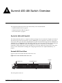
Summit 200 Series Switches
The Summit 200 series switches include the following switch models:
• Summit 200-24 switch
• Summit 200-48 switch
Both models of the Summit 200 switch are compact enclosures 1U in height (1.75 inches or 44.45 mm).
The Summit 200 provides either 24 or 48 autosensing 10BASE-T/100BASE-TX ports using RJ-45
connectors. The Summit 200 series also provides two 10/100/1000BASE-T Gigabit Ethernet uplink ports
using RJ-45 connectors and two optical ports that also allow Gigabit Ethernet uplink connections
through Extreme 1000BASE-SX, 1000BASE-LX, or 1000BASE-ZX Small Form Factor pluggable (SFP)
Gigabit Interface Connectors (GBICs)—also known as mini-GBICs—using LC optical fiber connectors.
Mini-GBICs are purchased separately. For more information, contact your Extreme Networks Sales
Representative.
The two uplink ports are combination ports. Each combination port can be either 10/100/1000BASE-T
using RJ-45 connectors or the optical port using mini-GBICs. These combination ports are described
further in “Summit 200 Automatic Failover” on page 44,
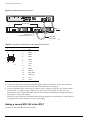
Summit 200 Switch Front View
The 24 port version of the Summit 200 is the Summit 200-24. Figure 5 shows the Summit 200-24 switch
front view. The 48 port version is the Summit 200-48, which is shown in Figure 6.
Consolidated "e" Series Hardware Installation Guide
41
Summit 200 Series Switch Overview
Figure 5: Summit 200-24 switch front view
10/100 Mbps ports
Mini-GBIC
port status LEDs
1000-baseT ports
Unit stacking Console
port
ID LED
Mini-GBIC ports
LC24001A
Figure 6: Summit 200-48 switch front view
10/100 Mbps ports
Mini-GBIC ports
Console
port
1000-baseT ports
LC48001
NOTE
See “Evaluating and Meeting Mini-GBIC Requirements” on page 31 for information about supported
GBIC types.
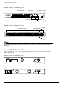
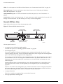
Summit 200 Switch Rear View
Figure 7 shows the rear view of the Summit 200-24 switch, while Figure 8 shows the rear view of the
Summit 200-48 switch.
Figure 7: Summit 200-24 switch rear view
Power socket
LC24002
Figure 8: Summit 200-48 switch rear view
Power socket
LC48002
42
Consolidated "e" Series Hardware Installation Guide
Summit 200 Series Switches
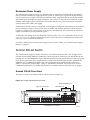
Power Socket
The Summit 200 switch automatically adjusts to the supply voltage. The power supply operates down
to 90 V.
Serial Number
Use this serial number for fault-reporting purposes.
MAC Address
This label shows the unique Ethernet MAC address assigned to this device.
NOTE
The Summit 200 switch certification and safety label is located on the bottom of the switch.
NOTE
See “Evaluating and Meeting Mini-GBIC Requirements” on page 31 for mini-GBIC types and distances.
Summit 200 Switch LEDs
Table 9 describes the light emitting diode (LED) behavior for both models of the Summit 200 switch.
Table 9: Summit 200 switch LED behavior
Unit Status LED (MGMT LED)
Color
Indicates
Green solid
The Summit switch is operating normally.
Green blinking
The Summit switch POST is in progress.
Amber
The Summit switch has failed its POST or an overheat condition
is detected.
Off
There is no power.
Fan Status LED
Color
Indicates
Green
The fan is operating normally.
Amber blinking A failed condition is present on the fan.
Port Status LEDs
Color
Indicates
Green
Link is present; port is enabled.
Green blinking
Link is present, port is enabled, and there is activity on the port.
Off
Link is not present or the port is disabled.
Consolidated "e" Series Hardware Installation Guide
43
Summit 200 Series Switch Overview
Table 9: Summit 200 switch LED behavior (continued)
Fiber Port Status LEDs (Ports 25 and 26 or Ports 49 and 50)
Color
Indicates
Green
Link is present; port is enabled.
Green blinking
Link is present, port is enabled, and there is activity on the port.
Off
Link is not present, port is disabled, or non-supported GBIC is
installed on the port.
Unit Stacking ID Number LED
Color
Indicates
N/A
When several Summit 200-24 switches are interconnected
(stacked), each switch will be assigned a unique stacking ID
number that will be visible in the unit stacking ID number LED.
The switch acting as the stack master will be assigned the
number 0, which is the default.
This LED is not available on the Summit 200-48
Console Port
Use the console port (9-pin, “D” type connector) for connecting a terminal and carrying out local
management.
Port Connections
A Summit 200 switch either has 24 or 48 10BASE-T/100BASE-TX ports using RJ-45 connectors for
communicating with end stations and other devices over 10/100Mbps Ethernet.
The switch also has four Gigabit Ethernet uplink ports, of which only two can be used at any one time.
These combination ports are labeled 25 and 26 on the front panel of the Summit 200-24 and labeled 49
and 50 on the front panel of the Summit 200-48. Two of the ports are 10/100/1000BASE-T ports using
RJ-45 connectors. The other two ports are unpopulated receptacles for mini-SFP GBICs, using optical
fibers with LC connectors. Both models of the Summit 200 support the use of 1000BASE-SX,
1000BASE-LX, or 1000BASE-ZX mini-GBICs.
NOTE
Only mini-GBICs that have been certified by Extreme Networks (available from Extreme Networks)
should be inserted into the mini-GBIC receptacles on the Summit 200 series switch.
Summit 200 Automatic Failover
The Summit 200 supports an automatic failover from an active fiber port to a copper back up or from an
active copper port to a fiber port. If one of the uplink connections fails, then the Summit 200 uplink
connection automatically fails over to the second connection. The preferred medium is fiber and cannot
be configured.
44
Consolidated "e" Series Hardware Installation Guide
Port Connections
On the Summit 200-24, ports 25 and 26 are the Gigabit Ethernet ports that have the redundant PHY
interfaces. On the Summit 200-48, it is ports 49 and 50. Each port has one mini-GBIC and 1000BASE-T
connection.
To set up a redundant link on either port 25 or on port 49, connect the active fibre and 1000BASE-T
links to both the RJ-45 and mini-GBIC interfaces of that port.
Summit 200-24 Switch Uplink Redundancy
Gigabit Ethernet uplink redundancy on the Summit 200-24 switch follows these rules:
• Ports 25 and 26 are Gigabit Ethernet ports that have redundant PHY interfaces, one mini-GBIC and
one 1000BASE-T connection for each port.
• Each of the uplink Gigabit Ethernet ports (25 and 26) can use either the mini-GBIC or the
1000BASE-T interface, but not both simultaneously.
• Only one interface on each port can be active at a time. For example, on port 25, with both the
mini-GBIC and 1000BASE-T interfaces connected, only one interface can be activated. The other is
inactive. If both interfaces are connected, the switch defaults to the fiber interface (mini-GBIC) and
deactivates the 1000BASE-T interface.
• If only one interface is connected, the switch activates the connected interface.
• To set up a redundant link on port 25, connect the active fibre and 1000BASE-T links to both the
RJ-45 and mini-GBIC interfaces of port 25. The switch defaults to the fiber link. If the fiber link fails
during operation, the switch automatically activates the redundant 1000BASE-T link.
Summit 200-48 Switch Uplink Redundancy
Gigabit Ethernet uplink redundancy on the Summit 200-48 switch follows these rules:
• Ports 49 and 50 are Gigabit Ethernet ports that have redundant PHY interfaces, one mini-GBIC and
one 1000BASE-T connection for each port.
• Each of the uplink Gigabit Ethernet ports (49 and 50) can use either the mini-GBIC or
the1000BASE-T interface, but not both simultaneously.
• Only one interface on each port can be active at a time. For example, on port 49, with both the
mini-GBIC and 1000BASE-T interfaces connected, only one interface can be activated. The other is
inactive. If both interfaces are connected, the switch defaults to the fiber interface (mini-GBIC) and
deactivates the 1000BASE-T interface.
• If only one interface is connected, the switch activates the connected interface.
• To set up a redundant link on port 49, connect the active fibre and 1000BASE-T links to both the
RJ-45 and mini-GBIC interfaces of port 49. The switch defaults to the fiber link. If the fiber link fails
during operation, the switch automatically activates the redundant 1000BASE-T link.
For information on the mini-GBIC, see “Evaluating and Meeting Mini-GBIC Requirements” on page 31.
NOTE
When configuring the Summit 200-48 switch, all ports specified as mirrored ports and mirroring port, or
ACL ingress ports and egress port, must belong to the same port group. Port group 1 consists of ports
1 through 24 and port 49; port group 2 consists of ports 25 through 48 and port 50.
Consolidated "e" Series Hardware Installation Guide
45
Summit 200 Series Switch Overview
Full-Duplex
Both models of the Summit 200 provide full-duplex support for all ports. Full-duplex allows frames to
be transmitted and received simultaneously and, in effect, doubles the bandwidth available on a link.
All 10/100 Mbps ports on the Summit 200 switch autonegotiate for half- or full-duplex operation.
46
Consolidated "e" Series Hardware Installation Guide
4
Summit 300 Switch Overview
This chapter describes the features and functionality of the Summit 300 series switch. It contains the
following sections:
• Summit 300 Series Switches on page 47
• Summit 300-24 Switch on page 47
• Summit 300-48 Switch on page 51
Summit 300 Series Switches
The Summit 300 series switches include the following switch models:
• Summit 300-24 switch
• Summit 300-48 switch
Summit 300-24 Switch
The Summit 300-24 supports wireless and Power over Ethernet (PoE) networks. This 1U high switch
provides 24 autosensing 10BASE-T/100BASE-TX ports using RJ-45 connectors. The Summit 300-24
series also provides two 10/100/1000BASE-T Gigabit Ethernet uplink ports or two optical ports. These
optical ports also allow Gigabit Ethernet uplink connections through Extreme 1000BASE-SX,
1000BASE-LX, or 1000BASE-ZX Small Form Factor pluggable (SFP) Gigabit Interface Connectors
(GBICs)—also known as mini-GBICs—using LC optical fiber connectors.
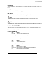
Summit 300-24 Front View
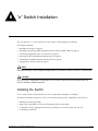
The 24-port version of the Summit 300 is the Summit 300-24. Figure 9 shows the Summit 300-48 switch
front view.
Consolidated "e" Series Hardware Installation Guide
47
Summit 300 Switch Overview
Figure 9: Summit 300-24 switch front view
10/100 Mbps ports
Management
LED
Fan LED
PSU LEDs
Console
port
Mini-GBIC
port status LEDs
10/100/1000-baseT ports
Mini-GBIC/
1000-baseX ports
RVN24001A
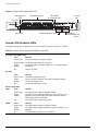
Summit 300-24 Switch LEDs
The light emitting diode (LED) behavior on the Summit 300-24 is described in Table 10.
Table 10: Summit 300-24 switch LED behavior (continued)
Unit Status LED (MGMT LED)
Color
Indicates
Green, solid
The Summit switch is operating normally.
Green, blinking The Summit switch POST is in progress.
Amber,
blinking
The Summit switch has failed its POST or an overheat condition
is detected.
Off
There is no power.
Color
Indicates
Green, solid
All fans are operating normally.
Amber,
blinking
One or more fans has failed. The switch continues to operate
unless over-heating occurs.
Off
The Summit switch has no power.
Fan LED
Power Supply LEDs
PSU-I
PSU-E
50
Color
Indicates
Green, solid
The internal power supply is operating normally.
Amber,
blinking
The internal power supply has failed, or the AC connector is not
plugged-in. If the power supply has failed, replace the internal
power supply as soon as possible.
Off
The internal power supply has no power.
Color
Indicates
Green, solid
The external power supply is operating normally.
Amber,
blinking
The external power supply has failed, or the AC connector is not
plugged-in.
Off
The external power supply is not connected.
Consolidated "e" Series Hardware Installation Guide
Summit 300-48 Switch
Table 10: Summit 300-24 switch LED behavior (continued)
Port Status LEDs (Ports 1-24)
Color
Indicates
Green, solid
Link is present and port is enabled; non-powered device.
Green, fast blinking
Port is enabled; link is up, device non-powered and activity on the
port.
Amber, solid
Link is present and port is enabled; device powered.
Amber, slow blinking
Link is down or port is disabled; device powered.
Amber, fast blinking
Port is enabled; link is up, device powered and activity on the
port.
Alternating amber/green
There is a power fault.
Off
The link is down or the port is disabled; non-powered device.
Fiber -LEDs (Ports 25—26)
Color
Indicates
Green
Link is present; port is enabled.
Green blinking
Link is present, port is enabled, and there is activity on the port.
Off
Link is not present, port is disabled, or non-supported GBIC is
installed on the port. The RJ-45 port is being used for the uplink.
Stack LEDs (Reserved for future features)
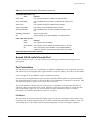
Summit 300-48 switchConsole Port
Use the console port (9-pin, “D” type connector) for connecting a terminal and carrying out local
management.
Port Connections
The Summit 300-24 switch uses a combination of 10BASE-T/100BASE-TX ports using RJ-45 connectors
and Small Form Factor Plugable (SFP) Gigabit Interface Connectors (GBICs), also known as mini-GBICs.
Ports 1 through 24 are 10/100BASE-T ports with RJ-45 connectors.
Ports 25 and 26 are Gigabit Ethernet ports that have redundant PHY interfaces for uplink redundancy.
The dual-media support consists of one mini-GBIC and one 1000BASE-T connection for each port. Only
one media type (fiber or copper) can be active at the same time.
The switch determines whether the port is the primary or redundant port based upon the order in
which the cables are inserted into the switch. When the switch senses that cables are in both the fiber
and corresponding copper port, the switch enables the uplink redundancy feature. For further
information, see “Summit 300 Automatic Failover” on page 53.
Full-Duplex
The Summit 300-24 switch provides full-duplex support for all ports. Full-duplex allows frames to be
transmitted and received simultaneously and, in effect, doubles the bandwidth available on a link. All
10/100 Mbps ports on the Summit 300-24 switch autonegotiate for half- or full-duplex operation.
Consolidated "e" Series Hardware Installation Guide
51
Summit 300 Switch Overview
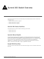
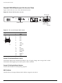
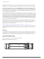
Summit 300-24 RearSummit 300-48 switch View
Figure 10 shows the rear view of the Summit 300-24 switch.
Figure 10: Summit 300-24 switch rear view
Slot for key
Power socket
Redundant
power cable
RVN24002
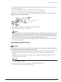
Figure 11: Pin outs for Summit 300-24 switch
Diagram
14
1
8
7
ES4K028A
Pin
Wire Label
1
GND
2
12V
3
12V
4
12V
5
12V
6
-50 V
7
-50 V rtn
8
GND
9
NC
10
rps_pres
11
EXT_CON
12
status_1
13
status_2
14
GND
Summit 300-48 switchPower Socket
The Summit 300-24 switch automatically adjusts to the AC supply voltage, with a range of 90V to 254V..
The Summit 300-24 applies power when a power cable is attached.
Summit 300-48 switchSerial Number
Use this serial number for fault-reporting purposes.
MAC Address
This label shows the unique Ethernet MAC address assigned to this device.
50
Consolidated "e" Series Hardware Installation Guide
Summit 300-48 Switch
Redundant Power Supply
The Summit 300-24 supports Power over Ethernet (PoE) as defined by the IEEE 802.3af specification.
PoE is an effective method of supplying 48 VDC power to certain types of powered devices (PDs) by
way of Category 5 or Category 3 twisted pair Ethernet cables. Supported devices include the Altitude
300 wireless port, IP telephones, laptop computers, web cameras, or other devices. With PoE, a single
Ethernet cable supplies power and the data connection, thereby saving time and expense associated
with separate power cabling and supply.
Summit 300-24 switch software is responsible for managing overall power consumption to ensure that it
does not attempt to delivery more power than is available. The Summit 300-24 has sufficient power
budget to provide full 15.4 watts power on all 24 ports simultaneously. An external 465 W AC power
supply is available to provide redundant power.
To determine the wattage of the installed PSUs when the PSUs are in 1-to-1 redundant mode, use the
show inline-power command. When in PoE mode, most of the power is dissipated externally to the
switch by way of the inside attached PDs.
For further details on the external power supply and its 1 meter cabling, see “External Power Supply
(45019)” on page 75.
Summit 300-48 Switch
The Summit 300-48 supports wireless and Power over Ethernet (PoE) networks. The 2U high switch
provides 48 autosensing10BASE-T/100BASE-TX ports using RJ-45 connectors. The Summit 300-48 also
provides two 10/100/1000BASE-T Gigabit Ethernet uplink ports using RJ-45 connectors and four optical
ports. These optical ports allow Gigabit Ethernet uplink connections through Extreme 1000BASE-SX,
1000BASE-LX, or 1000BASE-ZX Small Form Factor pluggable (SFP) Gigabit Interface Connectors
(GBICs)—also known as mini-GBICs—using LC optical fiber connectors. The optical ports are also
combination uplink ports. For further information, see “Summit 300 Automatic Failover” on page 53.
Summit 300-48 Front View
The 48-port version is the Summit 300-48, which is shown in Figure 12.
Figure 12: Summit 300-48 switch front view
10/100/1000 Mbps ports
Expansion module slot
Mini-GBIC ports
Console port
10/100 Mbps ports with PoE
LB48001
Consolidated "e" Series Hardware Installation Guide
51
Summit 300 Switch Overview
NOTE
See “Evaluating and Meeting Mini-GBIC Requirements” on page 31 for information about supported
mini-GBIC types and distances.
LED Behavior
The light emitting diode (LED) behavior for the Summit 300-48 is shown in Figure 11.
Table 11: Summit 300-48 switch LED behavior
Unit Status LED (MGMT LED)
Color
Indicates
Blinking Green The Summit switch is operating normally.
Solid Amber
The Summit has failed its POST.
Off
No power.
Power Supply Status LEDs (per power supply)
Color
Indicates
Solid Green
The power supply is operating normally.
Solid Amber
There is a fault.
Off
There is no power.
Fan Unit Status LEDs
Color
Indicates
Solid Green
The fan is operating normally.
Solid Amber
There is a fault.
Off
There is no power.
Power Supply Status LEDs
LED
Color
Indicates
OUT
Solid Green
The output voltages are enabled and within specification.
Off
There is a fault on at least one output voltage or voltages are out
of specification.
Solid Amber
The fan failed or there is an over temperature condition.
Off
The fan is operating normally and operating temperature is within
limit.
Solid Green
The input voltage is within specification and the input section is
working.
TEMP
IN
Off
The input voltage is out of range or there is a fault in the input
section.
50
Consolidated "e" Series Hardware Installation Guide
Summit 300-48 Switch
Table 11: Summit 300-48 switch LED behavior
10/100 Mbps Port Status LEDs
Color
Indicates
Green, solid
Link is present and port is enabled; non-powered device.
Green, fast blinking
Port is enabled; link is up, device non-powered and activity on the
port.
Amber, solid
Link is present and port is enabled; device powered.
Amber, slow blinking
Link is down or port is disabled; device powered.
Amber, fast blinking
Port is enabled; link is up, device powered and activity on the
port.
Alternating amber/green
There is a power fault.
Off
The link is down or the port is disabled; non-powered device.
10/100/1000 Mbps Port Status LEDs
Color
Indicates
Green solid
Link is present; port is enabled; full-duplex operation.
Green blinking
Link is present; there is activity.
ASummit 300-48
switchmber blinking
Reserved.
Link is not present or the port is disabled.
Off
Fiber Port Status LEDs
Color
Indicates
Solid Green
Link is present; port is enabled; full-duplex operation.
Blinking Green
Link is present; there is activity.
Off
Link is not present; port is disabled; mini-GBIC is not installed.
Console Port
Use the console port (9-pin, “D” type connector) for connecting a terminal and carrying out local
management.
Port Connections
The Summit 300-48 switch uses a combination of 10BASE-T/100BASE-TX ports using RJ-45 connectors
and Small Form Factor Plugable (SFP) Gigabit Interface Connectors (GBICs), also known as mini-GBICs.
Ports 1 through 48 are 10/100 ports with RJ45 connectors.
Summit 300 Automatic Failover
The Summit 300 switches provides dual-media support on GigE ports. On the Summit 300-24, ports 24
and 25 are Gigabit Ethernet ports that have redundant PHY interfaces, one mini-GBIC and one
Consolidated "e" Series Hardware Installation Guide
51
Summit 300 Switch Overview
1000BASE-T connection for each port. On the Summit 300-48 it is ports 1:49-1:52 that are dual-mode
redundant ports. Only one media type (fiber or copper) can be active at the same time on those ports.
The two fiber ports and the first two of the 10/100/1000BASE-T ports on the Summit 300-24 and the
four fiber ports and the first four of the 10/100/1000BASE-T ports are designed as combination ports
for uplink redundancy. When sharing ports, only the fiber medium or only the copper medium can be
active at the same time. If copper medium 1 goes down while transmitting packets, fiber medium 1X
activates and becomes the primary link.
The switch determines whether the port uses the primary or redundant media is based upon the order
in which the connectors are inserted into the switch. When the switch senses a mini-GBIC and a copper
connector are inserted, the switch enables the uplink redundancy feature. For example, if you first insert
mini-GBICs into ports 1:49 and 1:51 on the Summit 300-48, and then connect copper ports 1:1 and 1:3,
the switch assigns ports 1:1 and 1:3 as redundant ports. On the Summit 300-24, if you inserted a SFP
connector into port 24 and then a Ethernet cable connector into port 1, fiber becomes the primary uplink
port and port 1 becomes the redundant port.
Hardware determines when a link is lost and swaps the primary and redundant ports to maintain
stability. After a failover occurs, the switch keeps or sticks with the current port assignment until there
is another failure or a user changes the assignment using the CLI. To change the uplink failover
assignment, use the following command:
<Link>configure ports <nnn> preferred-medium {copper} | {fiber} |[force]
The default preferred-medium is fiber. If you use the force option, it disables automatic failover. If you
force the preferred-medium to fiber and the fiber link goes away, the copper link is not used, even if
available.
Full-Duplex
The Summit 300-48 switch provides full-duplex support for all ports. Full-duplex allows frames to be
transmitted and received simultaneously and, in effect, doubles the bandwidth available on a link. All
10/100 Mbps ports on the Summit 300-48 switch autonegotiate for half- or full-duplex operation.
Summit 300-48 Rear View
Figure 13 shows the rear view of the Summit 300-48 switch.
Figure 13: Summit 300-48 switch rear view
Power switch
PSU-B
PSU-A
Power socket
LB48002B
50
Consolidated "e" Series Hardware Installation Guide
Summit 300-48 Switch
Power Socket
The Summit 300-48 switch automatically adjusts to the supply voltage. The power supply operates
down to 90 V.
Power Switch
The Summit 300-48 switch has a power switch. Do not turn on power to the switch until instructed in
the installation procedures.
NOTE
Summit 300-48 switchThe Summit 300-48 switch certification and safety label, and the serial
number and MAC address labels are located on the bottom of the switch.
Load Sharing Power Supplies
The PoE subsystem in the Summit 300-48 supports dual power supplies for either redundant or
load-sharing modes. Redundant mode is the default and provides hitless PoE should one of the two
power supplies fail, be removed, or powered off. Load-sharing mode allows both power supplies to
provide power to the PoE system, providing greater PoE power capacity. For load-sharing operation,
the amount of power provided to the PoE system is the sum of the power supplied by the power
supplies.
NOTE
With load-sharing, all PoE devices may experience a power hit if a power supply fails.
The Summit 300-48 supports a 600 W AC internal power supply unit (PSU). The Summit 300-48
requires a minimum software level of ExtremeWare 6.2a.1.2.
To determine the wattage of the installed PSUs when the PSUs are in redundant mode, use the show
inline-power command. If System maximum internal inline-power field indicates 480 W, that
means that 600 W PSUs are installed.
For further details on power supplies, see “Summit 300 Optional Features” on page 75.
Consolidated "e" Series Hardware Installation Guide
51
Summit 300 Switch Overview
50
Consolidated "e" Series Hardware Installation Guide
5
Summit 400-48t Switch Overview
This chapter describes the features and functionality of the Summit 400-48t.
• Summit 400-48t Switch on page 57
• Summit 400 Switch LEDs on page 59
• Port Connections on page 61
Summit 400-48t Switch
The Summit 400-48t switch is a compact enclosure (see Figure 14) one rack unit in height (1.73 inches or
44.0 mm) that provides 48 autosensing 10/100/1000BASE-T ports using RJ-45 connectors. The switch
also has four fiber ports that allow Gigabit Ethernet uplink connections through Extreme 1000BASE-SX,
1000BASE-LX, or 1000BASE-ZX SFP mini-GBICs using LC connectors. The four fiber ports and the first
four of the 10/100/1000BASE-T ports are designed as shared, or combination ports for uplink
redundancy. When sharing ports, only the fiber port or only the copper port can be active at the same
time. For more information on cabling and configuring this feature, see “Uplink Redundancy” on
page 61.
Summit 400 Front View
Figure 14 shows the Summit 400-48t switch front view.
Figure 14: Summit 400-48t switch front view
Mini-GBIC ports
10/100 Mbps ports
Console
port
ES4K001
The front panel consists of:
Consolidated "e" Series Hardware Installation Guide
57
Summit 400-48t Switch Overview
LEDs—For a description of the LEDs and their behavior, see “Summit 400 Switch LEDs” on page 59.
Fiber uplink ports—For more information about these four ports, see “Evaluating and Meeting
Mini-GBIC Requirements” on page 31.
10/100/1000BASE-T ports—For more information about these 48 ports, see “Port Connections” on
page 61.
Console Port—Use the console port (9-pin, “D” type connector) to attach a terminal and access the CLI
through a serial connection. Use the console port to carry out local management.
Summit 400 Rear View
Figure 15 shows the rear view of the Summit 400-48t switch.
Figure 15: Summit 400-48t switch rear view
Compact flash
(reserved for future)
External power
supply connection
Mgmt port
10 Gigabit
uplink option
10 Gigabit stacking ports
(reserved for future)
Power socket
ES4K018A
The rear panel consists of:
• An option slot for the dual 10 Gigabit uplinks
To install this option, see “Installing Optional Features” on page 89.
• The management port
The 10/100/1000BASE-T Ethernet management port communicates directly with the CPU of the
switch, bypassing the switch. Connect an Ethernet cable directly from a laptop into the management
port to view and locally manage the switch configurations.
Do not assign an in-band IP address to the management port VLAN. The management port VLAN is
an out-of-band VLAN, so if it is assigned an in-band IP address (an address where the source and
destination are in the same subnet), the switch treats it as a normal VLAN and attempts to route
traffic through it.
Extreme Networks does not recommend that you use the management port to route traffic to any
front panel port on the switch. The management port is designed only for switch management
purposes.
There are two LEDs for the management port, located in the bottom corners of the port. The LED on
the bottom right turns solid green when a cable is inserted and the port detects a link. The LED on
the bottom left blinks green when there is transmission activity on the link.
• A compact flash slot
This slot is currently not supported but is reserved for future use.
• Two high-performance stacking ports
58
Consolidated "e" Series Hardware Installation Guide
Summit 400-48t Switch
These ports are currently not supported but are reserved for future software features.
• Vents for the internal power supply fan.
• The connector for the optional Extreme External Power Supply System.
For further information about this feature, see “Installing Optional Features” on page 89.
• AC Power Socket
The Summit 400-48t switch automatically adjusts to the supply voltage. The power supply operates
from 100 VAC to 240 VAC.
NOTE
The Summit 400-48t switch certification, safety label, and serial number are located on the bottom of
the switch.
Summit 400 Switch LEDs
The front panel displays five types of LEDs:
• Management
The MGMT LED indicates the status of the switch.
• Fan
The FAN LED indicates the status of the cooling fans.
• Power
The Summit 400-48t comes with an internal power supply and can be connected to the Extreme
External Power Supply tray. The status of the internal power supply is indicated by the PSU-I LED.
The status of the external power supply is indicated by the PSU-E LED.
• 10/100/1000BASE-T port status
Each of the 48 copper 10/100/1000BASE-T ports has an associated LED located above the port.
• Fiber port status
Each of the four optical fiber ports has an associated LED located above the port.
Table 12 describes the behavior of the front panel LEDs on the Summit 400-48t switch.
Consolidated "e" Series Hardware Installation Guide
59
Summit 400-48t Switch Overview
Table 12: Summit 400 switch LED behavior
Unit Status LED (MGMT LED)
Color
Indicates
Green, slow
blinking
The Summit switch is operating normally.
Green, fast
blinking
The Summit switch POST is in progress.
Green, solid
POST passed; ExtremeWare is booting.
Amber,
blinking
The Summit switch has failed its POST or an overheat condition
is detected.
Off
The Summit switch has no power.
Color
Indicates
Green solid
All fans are operating normally.
Fan Status
LED
Amber blinking One or more fans has failed. The switch continues to operate
unless over-heating occurs.
Off
The Summit switch has no power.
Power Supply LEDs
PSU-I
PSU-E
Color
Indicates
Green, solid
The internal power supply is operating normally.
Amber,
blinking
The internal power supply has failed. Replace the internal power
supply as soon as possible.
Off
The internal power supply has no power.
Color
Indicates
Green, solid
The external power supply is operating normally.
Off
The external power supply is not connected.
Port Status LEDs (Ports 1–48)
Color
Indicates
Green, solid
The link is present; port is enabled.
Green blinking
The link is present and the port is transmitting or receiving
packets.
Off
The link is not present.
Fiber LEDs(Ports 1X—4X)
Color
Indicates
Green, solid
Fiber link is selected; mini-GBIC is present and being used for the
Gigabit Ethernet uplink.
Green, blinking The link is present and the port is transmitting or receiving
packets.
Off
1000BASE-T link is selected; the switch is using the RJ-45 port
for the Gigabit Ethernet uplink.
Stack LEDs (Reserved for future features)
60
Consolidated "e" Series Hardware Installation Guide
Port Connections
Port Connections
The Summit 400-48t switch has 48 copper 10/100/1000BASE-T ports using RJ-45 connectors for
communicating with end stations and other devices over 10/100/1000 Mbps Ethernet.
The switch also has four fiber ports that allow Gigabit Ethernet uplink connections through Extreme
1000BASE-SX, 1000BASE-LX, or 1000BASE-SX SFP mini-GBICs using LC connectors. Fiber and
mini-GBIC specifications are covered in “Evaluating and Meeting Cable Requirements” on page 27 and
“Evaluating and Meeting Mini-GBIC Requirements” on page 31.
The switch provides full-duplex support for all ports. Full-duplex allows frames to be transmitted and
received simultaneously and, in effect, doubles the bandwidth available on a link. All 10/100/1000
Mbps ports on the Summit 400-48t switch autonegotiate for half- or full-duplex operation.
Uplink Redundancy
The four fiber ports and the first four of the 10/100/1000BASE-T ports are designed as combination
ports for uplink redundancy. When sharing ports, only the fiber port or only the copper port can be
active at the same time. If copper port 1 goes down while transmitting packets, fiber port 1X activates
and becomes the primary link. See Figure 16 for a diagram of these combination ports.
The switch determines whether the port is the primary or redundant port based upon the order in
which the cables are inserted into the switch. When the switch senses that cables are in both the fiber
and corresponding copper port, the switch enables the uplink redundancy feature. For example, if you
insert mini-GBICs into ports 1X and 3X first, and then connect copper ports 1 and 3, the switch assigns
ports 1 and 3 as redundant ports.
Figure 16: Redundancy cabling
1
3
1
3
2
4
2
4
ES4K019
You can override the configuration and behavior of these ports through the CLI. Using the CLI, you can
set a preference for either fiber or copper. You can also turn off port redundancy using the force option.
If a combination port fails to link, determine whether the force option is in effect. For more information
about using the CLI to set redundancy priority, see the ExtremeWare Software Users Guide.
The Summit 400-48 switch Gigabit Ethernet port failover from the fiber link to the copper link takes 4-5
seconds. The Summit 400-48t switch Gigabit Ethernet port failover from the copper link to the fiber link
takes 2-3 seconds.
Consolidated "e" Series Hardware Installation Guide
61
Summit 400-48t Switch Overview
NOTE
To support automatic failover between the fiber and copper ports, you must use an Extreme mini-GBIC
connector.
62
Consolidated "e" Series Hardware Installation Guide
Part 3
Switch Installation
6
“e” Switch Installation
You can mount an “e” series switch in a rack or place it free-standing on a tabletop.
This chapter describes:
• Installing the Switch on page 65
• Installing or Replacing a Mini-Gigabit Interface Connector (Mini-GBIC) on page 67
• Connecting Equipment to the Console Port on page 69
• Powering On the SwitchSummit 300-48 switch on page 70
• Checking the InstallationSummit 300-48 switch on page 70
• Logging In for the First Time on page 71
NOTE
Read the information in this chapter thoroughly before you attempt to install or remove a Summit switch.
CAUTION
Use of controls or adjustments of performance or procedures other than those specified herein can
result in hazardous radiation exposure.
Installing the Switch
An “e” series switch can be mounted in a rack, or placed free-standing on a tabletop.
To mount the Summit switch into a rack, you need the following tools, equipment, and resources:
• Mounting brackets (provided)
• Eight screws (provided) to secure the mounting bracket to the switch
• A minimum of four appropriate screws (not provided) to secure the switch into the rack
• # 1 Phillips screwdriver
Consolidated "e" Series Hardware Installation Guide
65
“e” Switch Installation
Rack Mounting
CAUTION
Do not use the rack mount kits to suspend the switch from under a table or desk, or to attach the switch
to a wall.
To rack mount the Summit 200 series switch:
1 Place the switch upright on a hard flat surface, with the front facing you.
2 Remove the existing screws from the sides of the case (retain the screws for Step 4).
3 Locate a mounting bracket over the mounting holes on one side of the unit.
4 Insert the screws and fully tighten with a suitable screwdriver, as shown in Figure 17.
Figure 17: Fitting the mounting bracket
LC24003
LB48004
ES4K002
5 Repeat steps 2 through 4 for the other side of the switch.
6 Insert the switch into the 19-inch rack.
• Take care to load the rack so that it is not top-heavy.
• Do not cover vents that would restrict airflow. Leave a half-rack space between the units for
adequate ventilation. This space is especially important for Summit 400-48t switches that have the
optional ER XENPAK transceiver installed.
7 Secure the switch with suitable screws (not provided).
8 Connect the switch to the redundant power supply (if applicable).
9 Connect cables.
66
Consolidated "e" Series Hardware Installation Guide
Installing or Replacing a Mini-Gigabit Interface Connector (Mini-GBIC)
Removing the Switch from a Rack
To uninstall an “e” series switch from a rack, you need a # 1 Phillips screwdriver. To remove the Summit
switch from a standard 19-inch (48.26 cm) rack:
1 Remove power from the switch.
• On the Summit 300-48, turn the power switch on the rear panel to the off position.
• Unplug the power cable(s) from the from the wall outlet(s) and then from the switch.
2 Disconnect the Summit switch from the redundant power supply (if applicable).
3 Unscrew the chassis from the rack.
4 Gently remove the chassis from the rack and place it on a secure, flat surface with the front of the
chassis facing you.
Free-Standing
All “e” series switches are supplied with four self-adhesive rubber pads. Apply the pads to the
underside of the device by sticking a pad in the marked area at each corner of the switch.
Desktop Mounting of Multiple Switches
You can physically place up to four “e” series switches on top of one another.
NOTE
This relates only to stacking the devices directly one on top of one another.
Apply the pads to the underside of the device by sticking a pad at each corner of the switch. Place the
devices on top of one another, ensuring that the corners align.
Installing or Replacing a Mini-Gigabit Interface Connector
(Mini-GBIC)
For your safety and to ensure proper installation, complete the following steps before inserting or
replacing mini-GBICs.
1 Read and comply with all of the safety instructions pertaining to fiber optic connections in “Optical
Safety” on page 100.
2 Read and follow the cable and connector planning requirements detailed in “Cabling Standards” on
page 27.
3 Disable the port that is needed to install or replace the mini-GBIC.
4 Inspect and clean the fiber tips, coupler, and connectors.
5 Prepare and clean an external attenuator, if needed.
6 Do not stretch the fiber.
7 Make sure the bend radius of the fiber is not less than 2 inches.
Consolidated "e" Series Hardware Installation Guide
67
“e” Switch Installation
In addition to the previously described tasks, Extreme Networks recommends the following when
installing or replacing mini-GBICs on an active network:
• Use the same type of mini-GBIC at each end of the link.
• Connect one end of the link to the Tx port. Without an attenuator, measure the total loss from the Tx
port to the other side of the link.
Once you complete all of the described tasks, you are ready to install or replace a mini-GBIC.
Removing and Inserting a Mini-GBIC
You can remove mini-GBICs from, or insert mini-GBICs into your “e” series switch without powering
off the system. Figure 18 shows the two types of mini-GBIC modules.
Figure 18: Mini-GBIC modules
Module A
Module B
XM_024
Mini-GBICs are a 3.3 V Class 1 laser device. Use only devices approved by Extreme Networks.
NOTE
If you see an amber blinking Mini-GBIC port status LED on your Summit 200 or Summit 300 series
switch, the mini-GBIC installed in your switch is one that is not approved or supported by Extreme
Networks. To correct this problem, ensure that you install a mini-GBIC that is approved and supported
by Extreme Networks.
Removing a Mini-GBIC
To remove a mini-GBIC similar to the one labeled “Module A” in Figure 18, gently press and hold the
black plastic tab at the bottom of the connector to release the mini-GBIC, and pull the mini-GBIC out of
the SFP receptacle on the switch.
To remove a mini-GBIC similar to the one labeled “Module B” in Figure 18, rotate the front handle
down and pull the mini-GBIC out of the slot.
68
Consolidated "e" Series Hardware Installation Guide
Connecting Equipment to the Console Port
Inserting a Mini-GBIC
To insert a mini-GBIC connector:
1 Holding the mini-GBIC by its sides, insert the mini-GBIC into the SFP receptacle on the switch.
Mini-GBICs can be installed in:
• Ports 25 and 26 on the Summit 200 and Summit 300-24 switches.
• Ports 49 through 52 on the Summit 300-48 switch.
• Ports 1X to 4X on the Summit 400-48t.
2 Push the mini-GBIC into the SFP receptacle until you hear an audible click, indicating the mini-GBIC
is securely seated in the SFP receptacle. If the mini-GBIC has a handle, push up on the handle to
secure the mini-GBIC.
Connecting Equipment to the Console Port
Connection to the console port is used for direct local management. The switch console port settings are
set as follows:
• Baud rate — 9600
• Data bits — 8
• Stop bit — 1
• Parity — None
• Flow control — None
NOTE
If you set the switch console port flow control to XON/XOFF rather than None, you will be unable to
access the switch. Do not set the switch console port flow control to XON/XOFF.
The terminal connected to the console port on the switch must be configured with the same settings.
This procedure is described in the documentation supplied with the terminal.
Appropriate cables are available from your local supplier. To make your own cables, pinouts for a DB-9
male console connector are described in Table 13.
Table 13: Console Connector Pinouts
Function
Pin Number
Direction
DCD (data carrier detect)
1
In
RXD (receive data)
2
In
TXD (transmit data)
3
Out
DTR (data terminal ready)
4
Out
GND (ground)
5
-
DSR (data set ready)
6
In
RTS (request to send)
7
Out
CTS (clear to send
8
In
Not Connected
9
Consolidated "e" Series Hardware Installation Guide
69
“e” Switch Installation
Figure 19 shows the pin-outs for a 9-pin to RS-232 25-pin null-modem cable.
Figure 19: Null-modem cable pin-outs
Summit
PC/Terminal
Cable connector: 9-pin female
Cable connector: 25-pin male/female
Screen Shell
TxD
3
RxD
2
Ground
5
RTS
7
CTS
8
DSR
6
DCD
1
DTR
4
1
3
2
7
4
20
5
6
8
Screen
RxD
TxD
Ground
RTS
DTR
CTS
DSR
DCD
ser_sum1
Figure 20 shows the pin-outs for a 9-pin to 9-pin PC-AT null-modem serial cable.
Figure 20: PC-AT serial null-modem cable pin-outs
Summit
PC-AT Serial Port
Cable connector: 9-pin female
Cable connector: 9-pin female
Screen Shell
DTR
4
TxD
3
RxD
2
CTS
8
Ground
5
DSR
6
RTS
7
DCD
1
Shell Screen
DCD
1
RxD
2
TxD
3
DTR
4
Ground
5
DSR
6
RTS
7
CTS
8
ser_sum2
Powering On the SwitchSummit 300-48 switch
Connect the AC power cable to the switch and then to the wall outlet. The Summit 300-48 has the
additional requirement to turn the power switch on the back panel to the on position..
Checking the InstallationSummit 300-48 switch
After connecting power to the switch, the device performs a Power On Self-Test (POST).
During the POST, all ports are temporarily disabled, the port LED is off, and the MGMT LED flashes.
The MGMT LED flashes until the switch successfully passes the POST.
If the switch passes the POST, the MGMT LED blinks at a slow rate (one blink per second). If the switch
fails the POST, the MGMT LED shows a solid amber light.
70
Consolidated "e" Series Hardware Installation Guide
Logging In for the First Time
NOTE
For more information on the LEDs, see Chapter 1.
Logging In for the First Time
After the switch completes the POST, it is operational. Once operational, you can log in to the switch
and configure an IP address for the default VLAN (named default).
To configure the IP settings manually, follow these steps:
1 Connect a terminal or workstation running terminal-emulation software to the console port.
2 At your terminal, press [Return] one or more times until you see the login prompt.
3 At the login prompt, enter the default user name admin to log on with administrator privileges.
For example:
login: admin
Administrator capabilities allow you to access all switch functions.
NOTE
For more information on switch security, see the ExtremeWare Software Users Guide.
4 At the password prompt, press [Return].
The default name, admin, has no password assigned. When you have successfully logged on to the
switch, the command-line prompt displays the name of the switch (for example, Summit200-24) in its
prompt.
5 Assign an IP address and subnetwork mask for VLAN default by typing
config vlan default ipaddress 123.45.67.8 255.255.255.0
Your changes take effect immediately.
6 Save your configuration changes so that they will be in effect after the next switch reboot, by typing
save
NOTE
For more information on saving configuration changes, see the ExtremeWare Software User Guide.
7 When you are finished using the facility, logout of the switch by typing
logout
NOTE
After two incorrect login attempts, the switch locks you out of the login facility. You must wait a few
minutes before attempting to log in again.
Consolidated "e" Series Hardware Installation Guide
71
“e” Switch Installation
72
Consolidated "e" Series Hardware Installation Guide
Part 4
Accessory Installation
7
Summit 300 Optional Features
This chapter describes how to install optional features on the Summit 300 family of switches. You can
order the following features from your Extreme sales representative:
• External Power Supply (45019) on page 75
• Internal 600 Watt Power Supply (15412) on page 79
External Power Supply (45019)
The Extreme Networks External Power Supply 45019 (EPS-LD) provides additional power to the
Summit 300-24. The EPS-LD provides 465 W total power with 375 W dedicated for PoE applications.
When attached to the Summit 300-24, the EPS-LD acts as a redundant power supply. The wattage is
sufficient to power all ports on the Summit 300-24 model.
The external power supply box contains the following items:
• One EPS-LD unit
• Mounting hardware, including screws
• One AC power cable for use in North America.
• One EPS-LD cable for connecting the power supply to the switch.
NOTE
If you are using the EPS-LD outside North America, the input power cord must have an IEC320-C14
connector and the appropriate power input plug for the country in which you are operating. The cord
must be 10 feet or less and at least 16-gauge copper wire.
CAUTION
The Extreme EPS-LD unit must only be installed or removed by trained service personnel in accordance
with the installation instructions. Before servicing this system, please read the safety information
provided in Appendix A. Not following these precautions can result in equipment damage or shock..
Consolidated "e" Series Hardware Installation Guide
75
Summit 300 Optional Features
Table 14 lists the electrical specifications for each EPS-LD unit.
Table 14: EPS-LD power supply specifications
Ratings
Nominal Operating Voltage
115 VAC or 230 VAC
Input Voltage Range
100 VAC to 240 VAC
AC Line Frequency
50 Hz to 60 Hz
Maximum Input Current Rating 10A at 115 VAC, 5A at 230 VAC
Maximum Inrush Current
30A at 115 VAC, 60A at 230 VAC
Output
-50 VDC, 7.5 A max, 375 Watts; 12 VDC, 7.5 A max, 90 Watts
EPS-LD Input Connector
IEC320-C14
Maximum continuous DC output shall not exceed 465 Watts.
Table 15 lists the environmental specifications for each EPS-LD unit.
Table 15: EPS-LD operational environmental specification overview
Ratings
Ambient Operating Temperature
0 C to +40 C
Storage and Transportation Temperature
-40 C to +70 C
Operating Relative Humidity
10 - 95% RH noncondensing
Shock—Operational
30 m/s2 (3g)
Rack-mounting the EPS-LD unit
NOTE
When installing an EPS-LD in a rack, make sure air vents are not restricted. Allow for elevated ambient
operating temperatures when installed adjacent to other equipment. Be sure you mount the equipment
within the rack so that the load is evenly distributed.
The EPS-LD unit can be mounted in a rack, or placed free-standing on a tabletop. You can mount the
EPS-LD facing either the front or the back of the rack. For this reason, each unit has two sets of
mounting holes; two on each end. Mounting the EPS-LD so that the unit’s output connectors are on the
same side as the external connector on the connecting switch.
CAUTION
Do not use the rack-mount kits to suspend the EPS-LD from under a table or desk, or to attach the
switch to a wall.
To install the EPS-LD, you need the following tools and materials:
• Electrostatic strap
• A #1 Phillips screwdriver
To rack mount each EPS-LD unit:
76
Consolidated "e" Series Hardware Installation Guide
External Power Supply (45019)
1 Place the EPS-LD unit upright on a hard flat surface, with the side you want to face to the front of
the switch toward you.
2 Remove the mounting bracket kit (including screws) from the packaging.
3 Locate a mounting bracket over the mounting holes on one side of the unit.
4 Insert the screws, as shown in Figure 21, and fully tighten the screws with a #1 Phillips screwdriver.
Figure 21: Fitting the mounting bracket
Collin's
ES4K026
XM_054
5 Repeat steps 2 through 4 for the other side of the EPS-LD unit.
6 Insert the EPS-LD unit into a 19-inch rack.
NOTE
Mount the EPS-LD so that the output connectors are on the same side as the external connector on
the connecting switch. If you mount the EPS-LD with the connectors facing in the opposite direction
as the Extreme switch connector, leave at least 1 U between the switch and the EPS-LD through
which to slide the cables. Do not route the cables around the equipment rack.
7 Insert the screws into the rack and the mounting bracket on both sides of the unit and fully tighten
with a suitable screwdriver.
Connecting the EPS-LD unit
CAUTION
Do not attach the AC power cord to the EPS-LD unit until the unit is properly grounded at the electrical
outlet and the redundant power supply cable is connected.
1 Connect the keyed end of the EPS-LD cable to the power supply unit(s). The key is a plastic tab on
the cable connector housing that fits into the EPS-LD unit to ensure correct alignment of the
connector.
See Figure 22 for details on the connector key, and see Figure 23 to locate the connectors on the
EPS-LD unit and on the switch.
NOTE
The cable length is 1 meter.
2 Connect the other end of the power supply cable to the Extreme switch.
The connector fits the slot in only one direction.
Consolidated "e" Series Hardware Installation Guide
77
Summit 300 Optional Features
Figure 22: EPS-LD cable with key
Collin's
ES4K027
XM_055
Figure 23: Cable connector for connecting an EPS-LD unit to a switch
Keyed end of
redundant power cable
Slot for key
EPS-LD
To AC
Extreme switch
Redundant
power cable
To AC
3 Connect the AC input power cable to the AC connector on the EPS-LD unit.
Collin's
CAUTION
The EPS-LD unit does not have a switch for turning the unit on and off. You disconnect power to the
EPS-LD unit by removing the plug from the electrical outlet. Ensure that this connection is easily
accessible to you.
4 Connect the other end of the AC cable into the electrical outlet.
Ensure that the electrical outlet is properly grounded.
NOTE
Consider all the equipment connected to the power supply circuit to ensure that the circuit is not
overloaded. Use proper overcurrent protection, such as a circuit breaker, to prevent overcurrent
conditions.
The Power LED on the front of the EPS-LD unit turns solid green to indicate that it is ready. Table 16
shows the possible LED status for the power supply.
Table 16: LED status for EPS-LD Power LED
Power LED
Indicates
Green, solid
The external power supply is operating normally.
Off
The external power supply is not connected.
78
Consolidated "e" Series Hardware Installation Guide
Internal 600 Watt Power Supply (15412)
Removing an EPS-LD unit
To remove an EPS-LD unit:
1 Disconnect the AC power by removing the plug from the wall.
2 Disconnect the AC power cord from the EPS-LD unit.
3 Remove the cable that connects to the Extreme switch from the EPS-LD unit.
4 Loosen the thumbscrews on the front of the EPS-LD mounting racks.
5 Slide EPS-LD unit out of rack.
Internal 600 Watt Power Supply (15412)
The Summit 300-48 600 Watt (W) power supply (15412) is designed to be used in the Summit 300-48
switch. While powering the Summit 300-48, the 600 W power supply is capable of providing 450 W of
power to Power over Ethernet (PoE) devices connected to the 48 primary PoE ports. Refer to the
Summit 300-48 Release Notes and “Redundant Power Supply” on page 51 to determine the total
available power at each port. You can obtain copies of these documents at the Extreme Networks web
site at:
http://www.extremenetworks.com/services/
The switch has two power supply bays, so a redundant power supply can be installed. When used in
redundant mode, the power supplies are hot-swappable. You can add a second power supply without
powering off the switch. If you have redundant power supplies installed, you can remove one of them
without powering off the switch.
The shipping container for the internal power supply contains the following items:
• One Summit 300-48 power supply
• Mounting hardware, including screws
• One AC power cable for use in North America
NOTE
If you are using the Summit 300-48 outside North America, the input power cord must have an
IEC60320-C13 connector and the appropriate power input plug for the country in which you are
operating. The cord must be 10 ft. or less in length and at least 18 gauge stranded copper wire.
CAUTION
This product must only be installed or removed by trained service personnel in accordance with the
installation instructions. Before servicing this system, be sure to read the safety information provided in
Appendix A. If you do not follow these precautions, it can result in equipment damage or shock.
This document contains the following sections:
• Removing and Installing Summit 300-48 Power Supplies on page 80
• Installing and Removing Power Cable Retaining Brackets on page 82
Consolidated "e" Series Hardware Installation Guide
79
Summit 300 Optional Features
• Internal Power Supply Technical Specifications on page 84
Removing and Installing Summit 300-48 Power Supplies
The Summit 300-48 comes with a minimum of one power supply pre-installed at the factory. Follow the
instructions in this section for removing and installing power supplies. Switches with one power supply
have a metal cover plate in place of the second supply. If you install a second power supply, be sure to
retain the cover plate in case you later decide to use only one supply.
Figure 24: Rear view of a Summit 300-48 showing two power supplies
LB48019A
Removing an Internal Power Supply
To remove an internal Summit 300-48 power supply:
1 Turn off the power supply by setting the power switch to the OFF position.
2 Remove the power cable from the power source, remove the power cable retaining bracket (if
installed), and then remove the power cable from the power supply.
CAUTION
Shock Hazard.
3 Use a #2 Phillips screwdriver to unscrew the two captive retaining screws. See the detail in Figure 24.
4 Grasp the retaining screws, and use them to slowly pull the power supply towards you, as shown in
Figure 25.
WARNING!
Do not insert your fingers or hands into the empty power supply bay.
80
Consolidated "e" Series Hardware Installation Guide
Internal 600 Watt Power Supply (15412)
Figure 25: Removing the Summit 300-48 power supply
LB48020A
5 If you are not going to install a replacement power supply, cover the power supply bay with the
blank cover plate that was originally supplied with the switch.
Installing an Internal Power Supply
To install an internal Summit 300-48 power supply:
1 Confirm that the power supply switch on the power supply to be installed is set to the OFF position.
2 Remove the power supply cable (if connected) from the power supply to be installed.
3 Remove the blank cover plate, or power supply, from the power supply bay.
WARNING!
Do not insert your fingers or hands into the empty power supply bay.
4 Grasp the retaining screws, and use them to gently slide the power supply into the bay.
5 Tighten the two captive retaining screws using a #2 Phillips screwdriver.
6 Install the power cable retaining bracket, if required, as described in the section “Installing the
Power Cable Retaining Bracket”. Otherwise, connect the power cable to the power supply and then
to the power source.
WARNING!
Do not turn on the power to the power supply unless the power supply is installed in the switch.
7 Set the power supply switch to the ON position.
8 Keep the cover plate and power supply packaging for future use.
Consolidated "e" Series Hardware Installation Guide
81
Summit 300 Optional Features
Installing and Removing Power Cable Retaining Brackets
The power cable for the Summit 300-48 power supply can be attached to the supply using power cable
retaining brackets. The retaining brackets make it less likely that a power supply cable will be
inadvertently knocked loose from a power supply.
Installing the Power Cable Retaining Bracket
To install a power cable retaining bracket:
1 Turn off the power supply by setting the power switch to the OFF position.
2 Disconnect the power cable from the power source and then disconnect the Summit 300-48.
3 Slide the retaining bracket over the power cable, as shown in Figure 26.
If necessary, loosen the retaining bracket screw.
Figure 26: Attaching the retaining bracket
Retaining bracket screw
LB48021B
82
Consolidated "e" Series Hardware Installation Guide
Internal 600 Watt Power Supply (15412)
Figure 27: Attaching the retaining bracket using spacers
Spacers
Bracket screws
LB48024
4 Connect the power cable to the switch
CAUTION
Do not connect the power cable to the power source at this time.
5 For power supplies with permanently attached standoffs, attach the retaining bracket to the power
supply using the bracket screws, as shown in Figure 26. For power supplies without permanently
attached standoffs, use the supplied spacers between the bracket and the power supply, as shown in
Figure 27.
6 Tighten the retaining bracket screw.
If your switch has two power supplies, align the retaining brackets, as shown in Figure 28, so that
the retaining bracket screws do not interfere with each other.
7 Connect the power cable to the power source.
8 Set the power supply switch to the ON position.
Consolidated "e" Series Hardware Installation Guide
83
Summit 300 Optional Features
Figure 28: Attaching two retaining brackets
Retaining bracket screw
Retaining bracket screw
LB48022A
Removing the Power Cable Retaining Bracket
To remove a power cable retaining bracket from a power cable:
1 Turn off the power supply by setting the power switch to the OFF position.
2 Disconnect the power cable from the power source.
3 Loosen the retaining bracket screw. See Figure 26 and Figure 28 for the location of the screws.
4 Gently remove the power cable from the power supply.
If you are installing a replacement power supply, follow the instructions in “Removing and Installing
Summit 300-48 Power Supplies” on page 80. After you install the replacement power supply, you need
to install a power cable retaining bracket. If you are installing a replacement power cable, you need to
tighten the power cable retaining bracket to the new cable (see Figure 28).
Internal Power Supply Technical Specifications
Summit 300-48 power supplies conform to the technical specifications described in this section.
LED Visual Indicators
The Summit 300-48 power supply has three LEDs that are visible from the rear of the Summit 300-48
when the supply is installed, as shown in Figure 29. The IN LED indicates the condition of the input
power (AC power source). When the input power is satisfactory, the IN LED is green, otherwise it is off.
The TEMP LED indicates the condition of the cooling fan or operating temperature. When the operating
temperature and fan cooling is satisfactory the TEMP LED is off, otherwise it is amber. The OUT LED
84
Consolidated "e" Series Hardware Installation Guide
Internal 600 Watt Power Supply (15412)
indicates the condition of the output DC power supplied by the power supply to the switch. When the
output power is satisfactory the OUT LED is green, otherwise it is off.
Figure 29: Power supply LEDs
LB48023
Table 17: Summit 300-48 power supply LED behavior
Condition
IN LED
Indication
TEMP LED
Indication
OUT LED
Indication
Normal
Green
Off
Green
Supply Inhibited or overloaded
Green
Off
Off
Input AC Low or Missing
Off
Off
Off
Fan Failure or Over Temperature
Green
Amber
Off
Consolidated "e" Series Hardware Installation Guide
85
Summit 300 Optional Features
Environmental and Safety Specifications
Table 18: Summit 300-48 power supply specifications
Safety
Agency Certifications and
Standards
North American Safety of ITE
•
UL60950 3rd Edition, Listed Device
•
CSA 22.2#60950-00
•
NOM/NYCE (Mexico Safety)
European Safety of ITE
•
EN60950:2000+All Available Country Deviations
•
73/23/EEC Low Voltage Directive
International Safety of ITE
•
CB Scheme IEC 60950:1999+All Country Deviations
•
AS/NZX 3260 (Australia /New Zealand)
•
GOST (Russia)
Electromagnetic Interference/
Compatibility (EMI/EMC)
Certifications and Standards
North America EMC for ITE
•
FCC CFR 47 part 15 Class A
•
ICES-003 Class A
European EMC standards for ITE
•
EN 55022:1998 Class A
•
EN 55024:1998 Class A (includes IEC 61000-4-2, 3, 4, 5, 6, 8, 11)
•
EN 61000-3-2,3 (Harmonics & Flicker)
•
ETSI EN 300 386:2001 (EMC Telecommunications)
•
89/336/EEC EMC Directive
International EMC Certifications
86
•
CISPR 22:1997 Class A
•
CISPR 24:1997 Class A
•
VCCI Class A (Japan)
•
AS/NZS 3548 (Australia)
•
CNS 13438:1997 Class A (BSMI-Taiwan)
•
MIC Mark (Korea)
Consolidated "e" Series Hardware Installation Guide
Internal 600 Watt Power Supply (15412)
Power Supply Specifications
Nominal Input Voltage
100/115/200/208/230 VAC
Input Voltage Range
85 VAC to 264 VAC
AC Line Frequency
47 Hz to 63 Hz
Power Supply Input
Connection
IEC60320 C13 with minimum 18 AWG stranded copper wire
Maximum Input Current
9.5 A @ 90 VAC, 6.95 A @ 115 VAC, 3.39 A @ 230 VAC
Total Output Power
600 W total, 450 W available for PoE applications
Temperature Power-off
65° to 75° C (149° to 167° F)
Environmental Operating Conditions
Operating Temperature
0° to 40° C (32° to 104° F)
Storage Temperature
-40° to 70° C (-40° to 158° F)
Operating Humidity
10% to 95% relative humidity, noncondensing
Operational Shock
30 m/s2 (3g)
Standards
EN/ETSI 300 019-2-1 v2.1.2 – Class 1.2 Storage
EN/ETSI 300 019-2-2 v2.1.2 – Class 2.3 Transportation
EN/ETSI 300 019-2-3 v2.1.2 – Class 3.1e Operational
EN/ETSI 300 753 (1997-10) – Acoustic Noise
ASTM D5276 Drop Packaged
ASTM D3580 Random Vibration Packaged 1.5G
Consolidated "e" Series Hardware Installation Guide
87
Summit 300 Optional Features
88
Consolidated "e" Series Hardware Installation Guide
8
Summit 400-48t Optional Features
This chapter describes how to install optional features on “e” series switches..
• Installing Optional Features on page 89
Installing Optional Features
Extreme Networks offers two hardware products that extend the capabilities of the Summit 400-48t. The
Summit XEN Card is an additional card that adds one or two 10 Gigabit uplink modules through the
back of the Summit 400-48t. The Extreme External Power System (EPS) allows you to add a redundant
power supply to the Summit 400 switch to protect against a power supply failure. Both of these
products are additional offerings and available from your sales representative.
Before installing any optional features, be sure to check the Installation Notes provided with the feature
to determine the latest installation process or limitations.
Installing the Summit XEN Card
The Summit 400-48t allows you to add up to two 10 Gigabit uplink modules to increase the bandwidth
of the switch. The Summit XEN Card supports either of these Extreme XENPAK optical transceivers:
• SR XENPAK for the 850 nm range
• LR XENPAK for the 1310 nm range
• ER XENPAK for the 1550 nm range
CAUTION
The Summit XEN Card cannot be hot-swapped. Before installing the Summit XEN Card into the Summit
400-48t, you must turn off the switch. Use only XENPAK modules approved by Extreme Networks.
To install the Summit XEN Card:
1 Disconnect the AC power from the Summit 400.
2 Use a standard screwdriver to remove the blank plate to expose the opening for the card.
3 Install the XENPAK optical transceiver modules onto the card. For more detail on this step, see
“Installing XENPAK Optical Transceiver Modules”.
Consolidated "e" Series Hardware Installation Guide
89
Summit 400-48t Optional Features
4 Place the Summit XEN Card into the drawer.
5 Carefully close the drawer to engage the card.
Installing XENPAK Optical Transceiver Modules
This section describes installing and removing the XENPAK module, a 10 Gbps optical transceiver. Both
the LR XENPAK and the ER XENPAK appear and install the same. An example of an XENPAK module
is shown in Figure 30.
Figure 30: XENPAK Modules
Card edge
connector
EWUG003B
The XENPAK module is a Class 1 Laser device that operates at 5 V. Use only Extreme-approved devices
on all Extreme switches.
CAUTION
The XENPAK module can emit invisible laser radiation. Avoid direct eye exposure to beam.
WARNING!
To prevent ESD damage to the Summit 400-48t, always use an ESD-preventive wrist strap when
installing or removing the module. Handle the module by its sides only. Never touch the card-edge
connectors at the insertion end of the module.
To install XENPAK modules:
1 Remove the XENPAK module from its antistatic container.
2 Remove the dust covers from the module connectors. If your module has a protective pad covering
the card-edge connector, remove it.
3 Store the antistatic container, dust covers, and card-edge connector protective pad in a clean location
in case you need to uninstall the module.
4 Hold the module by its sides and insert it into one of the two module slots on the Summit XEN card.
5 Slide the module as far back into the slot as possible, until you hear it click, indicating that it is
firmly attached.
90
Consolidated "e" Series Hardware Installation Guide
Installing Optional Features
6 Secure the module to the card by turning the two captive screws clockwise until they are hand-tight.
7 Place the Summit XEN Card into the supplied drawer and carefully slide the drawer into the switch
housing until the card seats and the drawer is flush with the remainder of the back panel.
8 Hand tighten the screws clockwise on the faceplate to keep the Summit XEN Card in place.
NOTE
To ensure that your module is undamaged upon installation, you can correlate factory test data with
your installation site test data by consulting the average power reference values shown on the XENPAK
module test data sheet (Part No. 121074-00) enclosed with your module.
To remove an XENPAK module:
1 Turn the two captive screws counter-clockwise until they are completely free from the Summit XEN.
(The captive screws remain attached to the XENPAK module.)
WARNING!
Remove the SC fiber-optic connector from the XENPAK module before removing the module from
the Summit XEN card.
2 Remove the SC fiber-optic connector from the XENPAK module.
WARNING!
XENPAK modules become very hot after prolonged use. Take care when removing a XENPAK from
the chassis. If the module is too hot to touch, disengage the module and allow it to cool before
removing it completely.
3 Gripping both captive screws, pull the XENPAK module out of the card.
4 Place the dust covers back into the XENPAK module connectors.
5 Place the XENPAK module immediately into an antistatic container to protect it from ESD damage
and dust.
Installing the External Power System
The Extreme External Power System (EPS) allows you to add a redundant power supply to the
Summit 400 switch to protect against a power supply failure. It consists of a tray (EPS-T) that holds one
or two EPS-160 power supplies. Each EPS-160 provides one-to-one redundancy to an attached Extreme
switch. Please check the Extreme website or with your local sales representative for a list of compatible
Extreme switches.
The EPS can be ordered with one or two EPS-160 power supplies. You can order an additional EPS-160
to add to an EPS system. If you do not already have an EPS-T, you can order one from your sales
representative. The EPS-160 installs into an existing EPS-T rack-mountable chassis.Each individual
EPS-160 ships with an AC cord for use in the USA and a special redundant power supply cable.
Consolidated "e" Series Hardware Installation Guide
91
Summit 400-48t Optional Features
CAUTION
The Extreme External Power System must only be installed or removed by trained service personnel in
accordance with the installation instructions. Before servicing this system, please read the safety
information provided in. Not following these precautions can result in equipment damage or shock.
Table 19 lists the specifications for each EPS-160 installed in the External Power System. Power supply
specifications along with compliance information is also available from the Extreme website.
Table 19: EPS-160 AC Power Supply Specifications
AC Input Specifications
Input Voltage
100 VAC to 240 VAC, 50 Hz to 60 Hz
Current Rating
4A at 100 VAC, 2A at 240 VAC
Maximum Inrush
Current
30A at 100 VAC, 50A at 50 VAC
Output Specifications
+12V DC, maximum output current 13A
+5V DC, maximum output current 1.5A
Rack Mounting the EPS-T
The EPS-T can be mounted in a rack, or placed free-standing on a tabletop.
CAUTION
Do not use the rack mount kits to suspend the EPS-T from under a table or desk, or to attach the
EPS-T to a wall.
WARNING!
The EPS-160, the EPS-T, and rack must be connected to protective earth ground before attaching to
another switch.
To rack mount the EPS-T:
1 Place the EPS-T upright on a hard flat surface, with the front facing you.
2 Remove the mounting bracket kit (including screws) from the packaging.
3 Locate a mounting bracket over the mounting holes on one side of the unit.
4 Insert the screws and fully tighten with a suitable screwdriver, as shown in Figure 31.
92
Consolidated "e" Series Hardware Installation Guide
Installing Optional Features
Figure 31: Fitting the mounting bracket
ES4K026
5 Repeat steps 2 through 4 for the other side of the EPS-T.
6 Insert the EPS-T into a 19-inch rack.
CAUTION
Do not attach the AC power cord to the EPS-160 until it is properly mounted in the EPS-T (that is
properly grounded) and after the redundant power supply cable is connected.
7 Connect the keyed-end of the redundant power supply cable to the EPS-160. The key is a plastic tab
on the cable connector housing that fits into the chassis to ensure correct alignment of the connector.
See Figure 32 for details on the connector key and Figure 33 to locate the connectors on the EPS-160
and the switch. Table 20 gives the wire-to-pin connections for the connector on the rear panel of the
EPS-160.
NOTE
The cable length is 1 meter.
Figure 32: Redundant Power Cable with Key
ES4K027
Consolidated "e" Series Hardware Installation Guide
93
Summit 400-48t Optional Features
Figure 33: Redundant Power Connection
Slot for plug
To AC
Keyed end of
redundant power cable
Redundant
power cable
ES4K021A
Table 20: Connection Specifications for the Redundant Connector
Diagram
1
8
7
14
ES4K028
Pin
Wire Label
1
NC
2
GND
3
GND
4
GND
5
GND
6
+12 V
7
+12 V
8
RS+
9
GND
10
INT PG
11
EXT_CON
12
EXT_PG
13
+5 V
14
+12 V
8 Connect the other end of each EPS-160 power supply cable to the Extreme switch. This connector
end can only be inserted into the switch with the end marked TOP facing up.
9 Using the supplied cable, connect the AC cable to the AC supply for each unit. For countries other
than the USA, you might require a different AC cable that is not supplied. Contact your sales
representative for the appropriate cable type and for information regarding the voltage and current
requirements of the power supply.
The PSU-E LED on the front of the EPS-160 should be solid green to indicate that it is ready. Table 12
on page 60 shows all the indicators for the power supply.
Adding a second EPS-160 to the EPS-T
To install an individual EPS-160 into the EPS-T:
94
Consolidated "e" Series Hardware Installation Guide
Installing Optional Features
1 Remove the EPS-160 from the packing material.
2 Insert the EPS-160 into the front of the EPS-T.
3 Tighten the provided thumbscrews to secure the power supply to the tray.
4 Follows steps 7 through 9 on page 93.
Removing an EPS-160 from the EPS-T
To remove an EPS-160 from an EPS-T:
1 Disconnect the AC by removing the plug from the wall
2 Disconnect the AC power cord from the EPS-160.
3 Remove the redundant power cable from the EPS-160.
4 Loosen the thumbscrews on the front of the tray and slide the EPS out of the EPS-T.
Consolidated "e" Series Hardware Installation Guide
95
Summit 400-48t Optional Features
96
Consolidated "e" Series Hardware Installation Guide
Part 5
Appendixes
A Safety Information
Important Safety Information
WARNING!
Read the following safety information thoroughly before installing your Extreme Networks switch. Failure
to follow this safety information can lead to personal injury or damage to the equipment.
Installation, maintenance, and removal of a switch, chassis, or its components must be done by qualified
service personnel only.
Qualified service personnel have had appropriate technical training and experience that is necessary to
be aware of the hazards to which they are exposed when performing a task and of measures to
minimize the danger to themselves or other people.
You should consider the following before unpacking your equipment:
• Install the equipment in a secured, enclosed, and restricted-access area, ensuring that only qualified
service personnel have access to the equipment.
• Install the equipment only in a temperature- and humidity-controlled indoor area that is free of
airborne materials that can conduct electricity. Too much humidity can cause a fire. Too little
humidity can produce electrical shock and fire.
• When you handle the equipment on modular switches, put on the ESD wrist strap to reduce the risk
of electronic damage to the equipment. Leave the ESD strap permanently attached to the chassis so
that it is always available when you need to handle ESD-sensitive components.
Power
The Summit series switch has either one or two power inputs depending on the switch model.
• Disconnect power before removing the back panel of a switch.
• Ground the unit. Do not connect the power supply unit to an AC outlet without a ground
connection.
• Connect the unit to a grounded outlet to comply with European safety standards.
• Place the unit near the socket outlet to be easily accessible. You can only remove power from the unit
by disconnecting the power cable from the outlet.
Consolidated "e" Series Hardware Installation Guide
99
Safety Information
• Operate the unit and attached equipment under Safety Extra Low Voltage (SELV) conditions. The “e”
series of switches operate under SELV conditions according to the IEC 950 standard. The conditions
are only maintained if the equipment to which it is connected also operates under SELV conditions.
• Ensure that the appliance coupler (the connector to the unit and not the wall plug) has a
configuration for mating with an EN60320/IEC320 appliance inlet.
• France and Peru only
Do not attempt to power the switch from IT† supplies. If your supplies are of IT type, the switch
must be powered by 230 V (2P+T) via an isolation transformer ratio 1:1, with the secondary
connection point labeled Neutral and connected directly to ground.
Power Cable
Use an AC power cable appropriate for your country. Check your local electrical codes and regulatory
agencies for power cable requirements. The countries listed below have the following additional
requirements:
• USA and Canada
— The cable set must be UL-listed and CSA-certified.
— The minimum specification for the flexible cable is No. 18 AWG (1.5 mm2), Type SVT or SJT,
3-conductor.
— The cable set must have a rated current capacity of at least the amount rated for each specific
product.
— The AC attachment plug must be an Earth-grounding type with a NEMA 5-15P (10 A, 125 V)
configuration.
• Denmark
— The supply plug must comply with section 107-2-D1, standard DK2-1a or DK2-5a.
• Switzerland
— The supply plug must comply with SEV/ASE 1011.
• Argentina
— The supply plug must comply with Argentinian standards.
NOTE
When using dual power supplies, make sure that each AC power supply attaches to an independent
power source.
Optical Safety
Fiber Optic ports. To protect your eyes, never look at the transmit LED/laser through a magnifying
device while it is powered on. Never look directly at a fiber port on the switch or at the ends of fiber
cable when they are powered on.
This is a Class 1 laser device. Use only devices approved by Extreme Networks.
100
Consolidated "e" Series Hardware Installation Guide
Important Safety Information
WARNING!
Use fiber optic ports only for data communications applications that require optical fiber. Use only with
the appropriate connector. When not in use, replace dust cover. Using this module in ways other than
those described in this manual can result in intense heat that can cause fire, property damage, or
personal injury.
Mini-GBICs. Remove the LC fiber-optic connector from the mini-GBIC prior to removing the
mini-GBIC from the switch.
Lithium Battery
The battery in the “e” series is encapsulated and not user-replaceable.
WARNING!
Danger of explosion if battery is incorrectly replaced. Replace only with the same or equivalent type
recommended by the manufacturer. Dispose of used batteries according to the manufacturer’s
instructions.
• Disposal requirements vary by country and by state.
• Lithium batteries are not listed by the Environmental Protection Agency (EPA) as a hazardous waste.
Therefore, they can typically be disposed of as normal waste.
• If you are disposing of large quantities, contact a local waste-management service.
• No hazardous compounds are used within the battery module.
• The weight of the lithium contained in each coin cell is approximately 0.035 grams.
• Two types of batteries are used interchangeably:
— CR chemistry uses manganese dioxide as the cathode material.
— BR chemistry uses poly-carbonmonofluoride as the cathode material.
Consolidated "e" Series Hardware Installation Guide
101
Safety Information
102
Consolidated "e" Series Hardware Installation Guide
B “e” Series Technical Specifications
This appendix describes the hardware technical specifications for “e” series of Extreme Network
switches. The appendix is organized into the following sections:
• Common Switch Specifications on page 103
• Summit 200 Series Switch Specifications on page 105
• Summit 300 Series Switch Specifications on page 106
• Summit 400 Series Switch Specifications on page 107
For information on the software technical specifications including protocols, MIBs, and standards, see
the ExtremeWare Software Users Guide.
Common Switch Specifications
The following technical specifications and certifications are common to all “e” series switches:
Table 21: Common switch specifications
Environmental Requirements
Operating Temperature
0° to 40° C (32° to 104° F)
Storage Temperature
-40° to 70 ° C (-40° to 158° F)
-10° to 70 ° C (14° to 158° F)
Operating Humidity
10% to 95% relative humidity, noncondensing
Standards:
EN60068 to Extreme IEC68 schedule EN 300 019 (Summit
200 and Summit 400)
Safety Certifications
North America
UL 60950 3rd Edition, listed (US Safety)
CAN/CSA-C22.2 No. 60950-00 (Canadian Safety)
International
CB Scheme
IEC60950:2000 with all country deviations (International
Safety)
Consolidated "e" Series Hardware Installation Guide
103
“e” Series Technical Specifications
Country Specific
Mexico NOM/NYCE (Product Safety and EMC Approval)
Australia/New Zealand AS/NZS 3260 (ACA DoC, Safety
of ITE)
Argentina S-Mark
GOST (Russia)
Laser Safety
North America
FCC 21 CFR subpart (J) (Safety of Laser Products)
CDRH Letter of Approval (US FDA Approval)
Europe
•
EN60825-2 (European Safety of Lasers)
•
EN60825-1:1994+A11:1996+A2 (European Safety of
Lasers Products) (Summit 300 only)
Electromagnetic
Compatibility
North America
FCC 47 CFR Part 15 Class A (US Emissions)
ICES-003 Class A (Canada Emissions)
Europe
89/336/EEC EMC Directive
ETSI/EN 300 386:2001 (EU Telecommunications Emissions
and Immunity)
EN55022:1998 Class A (European Emissions)
EN55024:1998 includes IEC/EN 61000-2, 3, 4, 5, 6, 11
(European Immunity)
EN 61000-3-2, -3 (Europe Harmonics and Flicker)
International
IEC/CISPR 22:1997 Class A (International Emissions)
IEC/CISPR 24:1998 (International Immunity)
IEC/EN 61000-4-2 Electrostatic Discharge (Summit 200 and
Summit 400 only)
IEC/EN 61000-4-3 Radiated Immunity (Summit 200 and
Summit 400 only)
IEC/EN 61000-4-4 Transient Bursts (Summit 200 and Summit
400 only)
IEC/EN 61000-4-5 Surge (Summit 200 and Summit 400 only)
IEC/EN 61000-4-6 Conducted Immunity (Summit 200 and
Summit 400 only)
IEC/EN 61000-4-11 Power Dips and Interruptions (Summit
200 and Summit 400 only)
Country Specific
Japan Class A (VCCI Registration Emissions)
Australia/New Zealand AS/NZS 3548 (ACA DoC, Emissions)
Korean MIC Mark (MIC Approval, Emissions and Immunity)
Mexico NOM/NYCE (Product Safety and EMC Approval)
GOST (Russia)
Taiwan CNS 13438:1997 Class A (BSMI Approval, Emissions)
Certification Marks
CE (European Community)
TUV/GS (German Notified Body)
TUV/S (Argentina)
GOST (Russian Federation)
104
Consolidated "e" Series Hardware Installation Guide
Summit 200 Series Switch Specifications
ACN 090 029 066
C-Tick (Australian Communication Authority)
Underwriters Laboratories (USA and Canada)
MIC (South Korea)
BSMI, Republic of Taiwan
NOM (Mexican Official Normalization, Electronic Certification
and Normalization)
Summit 200 Series Switch Specifications
The Summit 200 series has two models, a 24 port and a 48 port model. Table 23 lists the specifications
that are common to both models, while Table 23 and Table 24 give model specific information.
Table 22: Summit 200 Common Specifications
Temperature switch power-off (Listed by supply type)
Digital supplies, not Rev. C1:
Not drifting: 65° to 70° C (149° to 158° F)
Drifting: 50° C (122° F)
Digital supplies, Rev. C1:
70° to 75° C (158° to 167° F)
Power-One supplies, Rev. OL
and earlier:
60° to 65° C (140° to 149° F)
Power-One supplies, Rev. OM
and later:
75° C (167° F)
Power Supply
AC Line Frequency:
50 Hz to 60 Hz
Input Voltage Options:
90 VAC to 264 VAC, auto-ranging
Current Rating:
100-120/200-240 VAC 2.0/1.0 A 0.5/0.25A
AC Line Frequency:
50 Hz to 60 Hz
Table 23: Summit 200-24 Unique Specifications
Physical and Environmental
Dimensions
Height: 1.75 inches (4.44 cm)
Width: 17.3 inches (43.94 cm)
Depth: 8.1 inches (20.57 cm)
Weight
Weight: 5.72 lbs (2.6 kg)
Consolidated "e" Series Hardware Installation Guide
105
“e” Series Technical Specifications
Table 23: Summit 200-24 Unique Specifications
Physical and Environmental
Heat Dissipation, Watts/BTU
24.1 W
Table 24: Summit 200-48 Unique Specifications
Physical and Environmental
Dimensions
Height: 1.75 inches (4.44 cm)
Width: 17.3 inches (43.94 cm)
Depth: 12.2 inches (31.00 cm)
Weight
Weight: 9.7 lbs (4.4 kg)
Heat Dissipation, Watts/BTU
48.0 W
Summit 300 Series Switch Specifications
The Summit 300 series has two models, a 24 port and a 48 port model. Table 25 lists the specifications
that are common to both models, while Table 26 and Table 27 give model specific information.
Table 25: Summit 300 common specifications
Heat Dissipation
185 W maximum (631 BTU/hr maximum)
Summit 300-48 switchPower
Supply
AC Line Frequency
50 Hz to 60 Hz
Input Voltage Options
90 VAC to 264 VAC, auto-ranging
Current Rating
100-240 VAC 3.0/6.0 A max.
Summit 300-48
switchEnvironmental
Requirements
Standards
EN/ETSI 300 019-2-1 v2.1.2 - Class 1.2 Storage
EN/ETSI 300 019-2-2 v2.1.2 - Class 2.3 Transportation
EN/ETSI 300 019-2-3 v2.1.2 - Class 3.1e Operational
EN/ETSI 300 753 (1997-10)
- Acoustic Noise
ASTM D5276 Drop Packaged
ASTM D3580 Random Vibration Packaged 1.5G
Table 26: Summit 300-24 unique specifications
Physical -Dimensions
Summit 300-24
Height: 1.75 inches (44.45mm)
Width: 17.35 inches (440.69 mm)
Depth: 15.3 inches (388.62 mm)
Weight: 14 lbs. (6.35 kg)
106
Consolidated "e" Series Hardware Installation Guide
Summit 400 Series Switch Specifications
Table 27: Summit 300-48 unique specifications
Summit 300-48
switchPhysical Summit
300-48 switchSummit
300-48 switchDimensions
Summit 300-48
Height: 3.5 inches (8.89 cm)
Width: 17.25 inches (43.815 cm)
Depth: 18.25 inches (46.355 cm)
Weight (with one power supply unit): 14 lbs (6.35kg)
Summit 300-48 switchSwitch
Power-Off
Temperature power-off
149° F to 167° F (65° C to 75° C)
Summit 400 Series Switch Specifications
The Summit series has a single model, the Summit 400-48t, which has these characteristics:
Table 28: Summit 400-48t specifications
Physical and Environmental
Dimensions
Height: 1.73 inches (4.40 cm)
Width: 17.6 inches (44.1 cm)
Depth: 16.4 inches (41.6 cm)
Weight
Weight: 11 lbs (4.98 kg)
Heat Dissipation, Watts/BTU
160 W/0.152 BTU per second
Power Supply
AC Line Frequency:
50 Hz to 60 Hz
Input Voltage Options:
90 VAC to 264 VAC, auto-ranging
Current Rating:
100-120/200-240 VAC 2.0/1.0 A 0.5/0.25A
AC Line Frequency:
50 Hz to 60 Hz
Consolidated "e" Series Hardware Installation Guide
107
“e” Series Technical Specifications
108
Consolidated "e" Series Hardware Installation Guide
Index
Numerics
10 Gigabit uplinks
1000BASE-LX
1000BASE-SX
1000BASE-ZX
58, 89
30
30
30
A
AC power cable planning
AC power requirements
AC power socket
Summit 200 switches
Summit 300-24 switch
Summit 300-48
Summit 400
AC power switch
Summit 300-48 switch
Summit 300-48 switch
35
23
43
50
55
59
power switch55
agency certifications
airflow requirements
amperage, calculating
ANSI standards
automatic failover
setting up
Summit 200-24 rules
Summit 200-48 rules
Summit 300 rules
Summit 400-48t rules
86
24
37
37
62
44
45
45
53
61
B
bend radius
fiber optic
UTP
building codes
bundling cable
29
28
22
28
C
cable
distances
identification records
labeling
manager
planning for
requirements, meeting
Consolidated "e" Series Hardware Installation Guide
30
28
28
28
28
27
types
cabling for redundancy
cabling standards
ANSI
BISCI
certifications
all switches
Summit 300-48 power supply
Class 1 laser device (warning)
combination ports
defined
Summit 200
Summit 300
Summit 400
commercial building standards
compact flash
console port
connecting equipment to
Summit 200 switch
Summit 300-24 switch
Summit 300-48 switch
Summit 400 switch
conventions
30
61
37
27
103
86
100
61
44
54
57, 61
37
58
69
44
49
53
58
8
D
design standards
dimensions
Summit 200-24 switch
Summit 200-48 switch
Summit 300-24 switch
Summit 400-48t switch
distribution rack requirements
grounding the rack
mechanical recommendations
securing the rack
service access
space requirements
dual 10 Gigabit uplinks
installation
location on Summit 400
dual uplink ports
location on Summit 200 switches
location on Summit 300-24 switch
location on Summit 300-48 switch
location on Summit 400 switch
37
105
106
106
107
25
25
26
26
26
89
58
42
48
51
61
109
E
electrical codes, planning for
electromagnetic compatibility
Summit 200-24 switch
Summit 300-48 power supply
electrostatic discharge
environmental requirements
planning for
Summit 200-24 switch
Summit 200-48 switch
Summit 400-48t switch
EPS-160
EPS-T
ER XENPAK
External Power Supply EPS-LD
External Power System
I
23
104
86
29
24
105
106
107
91
91
89
75
89, 91
F
fan status LED
Summit 200 switches
Summit 300-24 switch
Summit 300-48 switch
Summit 400 switch
features, software
fiber optic cable
fiber port status LEDs
Summit 200 switches
Summit 300-24 switch
Summit 300-48 switch
Summit 400 switch
floor coverings
free-standing installation
front view
Summit 200 switches
Summit 300-24 switch
Summit 300-48 switch
Summit 400 switch
full-duplex
Summit 200 switches
Summit 300-24 switch
Summit 300-48 switch
Summit 400 switch
support
43
48
52
60
14
29
44
49
53
60
23
67
42
47
51
57
46
49
54
61
19
G
grounding
grounding the rack
37
25
H
hardware address
Summit 200-24 switch
Summit 300-24
Summit 300-48 switch
Summit 400 switch
heat dissipation
Summit 200-24 switch
Summit 200-48 switch
Summit 300 switches
Summit 400 switch
high-performance stacking ports
humidity
110
43
50
55
59
106
106
106
107
58
25
industry standards
installation
connecting network interface cables
free-standing
optional hardware
rack
installing cable
bend radius
cable distances
fiber optic cable
slack
internal power supply for Summit 300-48
37
34
67
89
65
28
28, 29
30
29
28
79
L
labeling cables
laser safety certifications
LEDs
back panel
front panel
Summit 200-24 switch
Summit 200-48 switch
Summit 300-24 switch
load sharing, power supplies
LR XENPAK
28
104
58
59
43
46
48 to 49
55
89
M
MAC address
Summit 200 switches
Summit 300-24 switch
Summit 400 switch
management port
management port LED
media types and distances
mini-GBIC
installation
removal
specifications
43
50
59
58
58 to 60
30
67
68
31 to 32
O
operating environment, planning
optical safety precautions
optical-fiber cable connections
optional hardware features
22
100
34
89
P
PD
plenum-rated cable
port connections
Summit 200 switches
Summit 300-24 switch
Summit 300-48 switch
Summit 400 switch
port status LEDs
Summit 200 switches
Summit 300-24 switch
Summit 300-48 switch
Summit 400 switch
power cable, replacing
power requirements
power supply
external installation
51
28
44
49
53
61
43
49
53
60
36
34 to 37
89, 91
Consolidated "e" Series Hardware Installation Guide
load sharing
specifications
uninterruptable
power supply LEDs
Summit 300-24
Summit 300-48
Summit 400
Summit 400 switch
powered device
power-off specifications
Summit 200-24 switch
55
105 to 107
36
48
52
60
59
51
105
R
rack mounting the switch
rack specifications
grounding
mechanical recommendations
mounting holes
securing to floor
space requirements
radio frequency interference
avoiding
cable installation
precautions and planning
recording cable locations
redundant Gigabit uplink port
Summit 200-24 rules
Summit 200-48 rules
Summit 300 rules
Summit 400 rules
redundant power installation
related publications
removing the switch from a rack
removing XENPAK modules
RJ-45 cables
running cable
bend radius
cable distances
fiber optic cable
slack
66
25
25
25
26
26
34
28
34
28
45
45
53
61
78, 94
8
67
91
33
28
28, 29
30
29
28
S
safety certifications
safety information
safety specifications
securing the rack
serial port. See console port
service access to the rack
site planning process
socket, AC power
Summit 200 switches
Summit 300-24 switch
Summit 300-48
space requirements for the rack
SR XENPAK
stack LED
standards
cabling
commercial building
grounding
Summit 200 switches
free-standing installation
port connections
Consolidated "e" Series Hardware Installation Guide
103 to 107
99
86
26
26
22
59
43
50
55
26
89
49, 60
37
37
37
67
44
rack mounting
Summit 200-24 switch
dimensions
electromagnetic compatibility
environmental requirements
front view
heat dissipation
LEDs
MAC address
power socket
power-off specifications
rear view
serial number
weight
Summit 200-48 switch
dimensions
environmental requirements
heat dissipation
LEDs
weight
Summit 300 switches
heat dissipation
Summit 300-24 switch
front view
MAC address
port connections
Summit 300-48 switch
console port
load sharing power supplies
optional power supply
port connections
rear view
Summit 400 switch
AC power socket
dimensions
environmental requirements
front view
heat dissipation
LED behavior (table)
physical features
port connections
rear view
weight
Summit switch, general
features
models
port connections
Summit XEN card
66
105
104
105
41
106
43
43
43
105
42
43
105
106
106
106
46
106
106
47
50
49
53
55
79
53
54
59
107
107
57
107
60
57
61
58
107
14
13
18
89
T
temperature
wiring closet
temperature
temperature of wiring closet
tools needed for installation
24
23
65
U
uninstalling, rack
uninterruptable power supply
calculating amperage requirements
features
selecting
transition time
67
37
36
36
36
111
uplink redundancy
setting up
Summit 200-24 rules
Summit 200-48 rules
Summit 300 switches
Summit-400 switch
UPS, See uninterruptable power supply
44
45
45
54
61
W
weight
Summit 200-24
Summit 200-48
Summit 400 switch
wiring closet
airflow requirements
grounding
humidity
planning
wiring terminals
105
106
107
24
24
25
23
25
X
XENPAK optical transceivers
112
89
Consolidated "e" Series Hardware Installation Guide