1
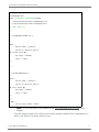
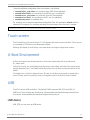
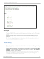
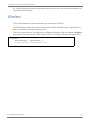
ConnectCore ® 6 Linux BSP Reference Manual 90001403_A Revision Record Revision Date (MM/DD/YY) Description A 05/22/2014 Preliminary draft release Copyright and Trademarks © 2014 Digi International Inc. All rights reserved. Digi, Digi International, the Digi logo, and ConnectCore 6® are trademarks or registered trademarks in the United States and other countries worldwide. All other trademarks mentioned in this document are the property of their respective owners. Information in this document is subject to change without notice and does not represent a commitment on the part of Digi International. Digi provides this document “as is,” without warranty of any kind, expressed or implied, including, but not limited to, the implied warranties of fitness or merchantability for a particular purpose. Digi may make improvements and/or changes in this manual or in the product(s) and/or the program(s) described in this manual at any time. Contacting Technical Support Digi International Inc. World Headquarters 11001 Bren Road East Minnetonka, MN 55343 Phone: (866) 765-9885 toll-free U.S.A. & Canada (801) 765-9885 Worldwide 8:00 am - 5:00 pm (U.S. Mountain Time) Online Support: www.digi.com/support/ Email: [email protected] Fax: 952-912-4952 ConnectCore 6 Linux BSP Reference Manual Table of Contents About the ConnectCore 6 Linux BSP. . . . . . . . . . . . . . . . . . . . . . . . . . . . . . . . . . . . . . . 4 Linux Kernel Device Tree. . . . . . . . . . . . . . . . . . . . . . . . . . . . . . . . . . . . . . . . . . . . . . . . . . . . . .4 Introduction . . . . . . . . . . . . . . . . . . . . . . . . . . . . . . . . . . . . . . . . . . . . . . . . . . . . . . . . . . 4 Advantages . . . . . . . . . . . . . . . . . . . . . . . . . . . . . . . . . . . . . . . . . . . . . . . . . . . . . . . . . . . 4 Formats . . . . . . . . . . . . . . . . . . . . . . . . . . . . . . . . . . . . . . . . . . . . . . . . . . . . . . . . . . . . . 4 Platform Device Tree Files. . . . . . . . . . . . . . . . . . . . . . . . . . . . . . . . . . . . . . . . . . . . . . . . . 5 Unsupported Devices . . . . . . . . . . . . . . . . . . . . . . . . . . . . . . . . . . . . . . . . . . . . . . . . . . . . . . . .5 Bluetooth. . . . . . . . . . . . . . . . . . . . . . . . . . . . . . . . . . . . . . . . . . . . . . . . . . . . . . . . . . . . . . . . .5 CAN Bus . . . . . . . . . . . . . . . . . . . . . . . . . . . . . . . . . . . . . . . . . . . . . . . . . . . . . . . . . . . . . . . . .5 Ethernet . . . . . . . . . . . . . . . . . . . . . . . . . . . . . . . . . . . . . . . . . . . . . . . . . . . . . . . . . . . . . . . . .6 GPIO . . . . . . . . . . . . . . . . . . . . . . . . . . . . . . . . . . . . . . . . . . . . . . . . . . . . . . . . . . . . . . . . . . . .8 I2C . . . . . . . . . . . . . . . . . . . . . . . . . . . . . . . . . . . . . . . . . . . . . . . . . . . . . . . . . . . . . . . . . . . . .8 One-Time Programmable (OTP) Bits. . . . . . . . . . . . . . . . . . . . . . . . . . . . . . . . . . . . . . . . . . . . . .8 Real Time Clock (RTC) . . . . . . . . . . . . . . . . . . . . . . . . . . . . . . . . . . . . . . . . . . . . . . . . . . . . . . .9 SD/SDIO/MMC controller . . . . . . . . . . . . . . . . . . . . . . . . . . . . . . . . . . . . . . . . . . . . . . . . . . . . . .9 Serial port . . . . . . . . . . . . . . . . . . . . . . . . . . . . . . . . . . . . . . . . . . . . . . . . . . . . . . . . . . . . . . . .9 Serial Peripheral Interface (SPI). . . . . . . . . . . . . . . . . . . . . . . . . . . . . . . . . . . . . . . . . . . . . . . . 10 Sound . . . . . . . . . . . . . . . . . . . . . . . . . . . . . . . . . . . . . . . . . . . . . . . . . . . . . . . . . . . . . . . . . . 10 Touch screen . . . . . . . . . . . . . . . . . . . . . . . . . . . . . . . . . . . . . . . . . . . . . . . . . . . . . . . . . . . . . 11 U-Boot Environment . . . . . . . . . . . . . . . . . . . . . . . . . . . . . . . . . . . . . . . . . . . . . . . . . . . . . . . . 11 USB . . . . . . . . . . . . . . . . . . . . . . . . . . . . . . . . . . . . . . . . . . . . . . . . . . . . . . . . . . . . . . . . . . . 11 USB device . . . . . . . . . . . . . . . . . . . . . . . . . . . . . . . . . . . . . . . . . . . . . . . . . . . . . . . . . . 11 Serial gadget . . . . . . . . . . . . . . . . . . . . . . . . . . . . . . . . . . . . . . . . . . . . . . . . . . . . . . 12 Ethernet gadget . . . . . . . . . . . . . . . . . . . . . . . . . . . . . . . . . . . . . . . . . . . . . . . . . . . . 12 File-backed mass storage gadget . . . . . . . . . . . . . . . . . . . . . . . . . . . . . . . . . . . . . . . . 12 USB Host. . . . . . . . . . . . . . . . . . . . . . . . . . . . . . . . . . . . . . . . . . . . . . . . . . . . . . . . . . . . 13 Video . . . . . . . . . . . . . . . . . . . . . . . . . . . . . . . . . . . . . . . . . . . . . . . . . . . . . . . . . . . . . . . . . . 13 Backlight . . . . . . . . . . . . . . . . . . . . . . . . . . . . . . . . . . . . . . . . . . . . . . . . . . . . . . . . . . . . 14 Watchdog . . . . . . . . . . . . . . . . . . . . . . . . . . . . . . . . . . . . . . . . . . . . . . . . . . . . . . . . . . . . . . . 14 Wireless . . . . . . . . . . . . . . . . . . . . . . . . . . . . . . . . . . . . . . . . . . . . . . . . . . . . . . . . . . . . . . . . 15 © 2014 Digi International Inc. iii ConnectCore 6 Linux BSP Reference Manual About the ConnectCore 6 Linux BSP This is a guide to supported devices and interfaces of the ConnectCore 6 platform in Digi Embedded Yocto 1.6. Linux Kernel Device Tree Introduction The Flattened Device Tree (FDT, or simply DT) is a data structure for describing the hardware in a system. Rather than hard coding every detail of a device into the operating system, many aspects of the hardware can be described in a data structure that is passed to the operating system at boot time. The data structure itself is a simple tree of named nodes and properties. Nodes contain properties and child nodes. Properties are simple name-value pairs. The structure can hold any kind of data. The format is expressive and able to describe most board design aspects including: • • • • • The number and type of CPUs Base addresses and size of RAM Busses and bridges Peripheral device connections Interrupt controllers and IRQ line connections Advantages • Ship one FDT image per machine (a few kB) instead of one kernel image per machine (several MB). • Reduce or eliminate effort needed to write machine support code (i.e. arch/arm/mach-*). Most board specific code changes constrained to FDT file and device drivers. • No need to allocate a new global ARM machine id for each new board variant. • Reduce the need to recompile the kernel. One kernel image with support for different hardware can be shipped and be run in different variants (each one with its own FDT describing the hardware which is really available). • Expressive format to describe related board variants without allocating new machine numbers or new ATAGs. • U-Boot firmware can inspect and modify an FDT image before booting. Formats • *.dts: This is a Device Tree file in plain text (human readable). • *.dtsi: This is like a DTS include file (a plain text file to be included by a DTS file). • *.dtb: This is a Device Tree Blob: a binary representation of a Device Tree, once compiled with the Device Tree compiler. © 2014 Digi International Inc. 4 ConnectCore 6 Linux BSP Reference Manual Platform Device Tree Files The DTS file for the ccimx6adpt platform can be found in the kernel source code tree under: arch/arm/boot/dts/imx6-ccimx6adpt-ldo.dts This DTS file includes other DTS and DTSI file in the same path. Unsupported Devices The following devices or interfaces are not supported in the BSP of the Early Availability (EA) Kit: • • • • • ADC Camera LCD parallel interface Power management PWM (on CPU) Bluetooth Bluetooth (if supported by the Atheros wireless chip variant) is connected to UART2. The MAC address of the Bluetooth interface is taken from U-Boot environment variable btaddr which is populated by U-Boot on the Device Tree before booting Linux. There is no generic Device Tree binding for the Bluetooth interface. Digi has created a bluetooth entry node to pass the driver the MAC address (filled-in by U-Boot) and the power down GPIO. bluetooth { digi,pwrdown-gpios = <&gpio_extender 4 0>; /* U‐Boot will fill in the MAC address here */ }; Note: Due to a HW bug in the module, Bluetooth is not supported in version 1 of the ConnectCore 6 module. CAN Bus The CPU has two Flexcan CAN ports. The CAN support is based on the SocketCAN stack. For more information about this project, documentation, and API, please refer to http:// developer.berlios.de/projects/socketcan/. FlexCAN Device Tree binding is described at Documentation/devicetree/bindings/net/can/fsl- flexcan.txt © 2014 Digi International Inc. 5 ConnectCore 6 Linux BSP Reference Manual Information about programming the CAN socket interface is given in the kernel tree under Documentation/networking/can.txt. Each CAN port appears like a networking interface in the form canx where x is the port number. The ports are disabled by default. To configure the CAN, first the bitrate must be set using ip tool, for example: # ip link set can0 type can bitrate 500000 To enable a port execute this command (specifying the appropriate port number): # ifconfig can0 up A sample application called can_test is available and can be added to the rootfs by adding “deyexamples” to the EXTRA_IMAGE_FEATURES of your local.conf or by adding “dey-examplescan” to IMAGE_INSTALL_append. This sample application performs several operations on the CAN node, like sending and receiving messages. An additional CAN node is needed in the other end of the bus for the application to work (a CAN analyzer, for example). For example, to send an 8-bit CAN message to node 'can0' with ID '0x12' and the data pattern '0x65': # can_test -l 1 -b 8 -d can0 -i 0x12 -p 0x65 -m And to receive a similar message: # can_test -l 1 -b 8 -d can0 -i 0x12 -p 0x65 For more information see the applications help with can_test --help. Ethernet The ConnectCore 6 supports both Gigabit and 10/100 Ethernet. By default, the Ethernet interface is configured for Gigabit. FEC driver Device Tree binding is described at Documentation/devicetree/bindings/net/fsl-fec.txt To configure Ethernet for 10/100 you need to do the following change to the Device Tree: © 2014 Digi International Inc. 6 ConnectCore 6 Linux BSP Reference Manual diff ‐‐git a/arch/arm/boot/dts/imx6‐ccimx6qdladpt.dtsi b/arch/arm/boot/dts/imx6‐ ccimx6qdladpt.dtsi index cb713e47d833..0a6adaa4e08d 100644 ‐‐‐ a/arch/arm/boot/dts/imx6‐ccimx6qdladpt.dtsi +++ b/arch/arm/boot/dts/imx6‐ccimx6qdladpt.dtsi @@ ‐200,7 +200,7 @@ }; /* 10/100/1000 KSZ9031 PHY */ +/* &fec { pinctrl‐names = "default"; pinctrl‐0 = <&pinctrl_enet_4>; @@ ‐211,10 +211,9 @@ phy‐supply = <&ldo4>; status = "okay"; }; +*/ /* 10/100 LAN8710 PHY */ ‐/* &fec { pinctrl‐names = "default"; pinctrl‐0 = <&pinctrl_enet_5>; @@ ‐225,7 +224,6 @@ phy‐supply = <&ldo4>; status = "okay"; }; ‐*/ &gpc { fsl,cpu_pupscr_sw2iso = <0xf>; Note: Due to a HW bug on the Adapter board, 10/100 Ethernet does not work on the Adapter. The MAC address is taken from U-Boot environment variable ethaddr which is populated by UBoot on the Device Tree before booting Linux. © 2014 Digi International Inc. 7 ConnectCore 6 Linux BSP Reference Manual The Freescale i.MX6 CPU has a documented errata ERR004512 whereby the maximum performance of Gigabit ENET is limited to 400Mbps (total for Tx and Rx). GPIO The CPU has seven GPIO ports, six with 32 GPIOs and one with 14 GPIOs. GPIOs are multiplexed with different functionalities of the chip. IOMUX of the pins is done at the device tree. GPIO Device Tree binding is described at Documentation/devicetree/bindings/gpio/fsl-imx- gpio.txt The GPIOs can be easily accessed from the sysfs. For information about how to manage the GPIOs from sysfs, refer to the Linux kernel documentation at Documentation/gpio.txt. The JSCCWMX53 development board contains two user LEDs and two user buttons that can be used to test the GPIOs. User LED1 User LED2 User Button 1 User Button 2 Port pin GPIO2_2 GPIO2_3 GPIO2_4 GPIO2_5 Linux gpio # 34 35 36 37 A sample application called gpio_sysfs_test is available and can be added to the rootfs by adding “dey-examples” to the EXTRA_IMAGE_FEATURES of your local.conf or by adding “deyexamples-gpio-sysfs” to IMAGE_INSTALL_append. I2C The CPU has three I2C ports. I2C2 is connected to the Dialog DA9063 PMIC and the Kinetis CPU and cannot be used for other peripherals. I2C3 is connected to the HDMI, LCD touch screen, camera, audio codec, and routed to the Adapter board for additional peripheral connections on the development board. I2C Device Tree binding is described at Documentation/devicetree/bindings/i2c/i2c-imx.txt. One-Time Programmable (OTP) Bits The i.MX6 CPU contains several one-time programmable bits (also known as e-fuses). The OTP bits can be read and programmed through the sysfs, under /sys/fsl_otp. WARNING: Programming the OTP bits is an irreversible operation that could potentially brick your module. Please don’t program the OTP bits unless you are sure of what you are doing © 2014 Digi International Inc. 8 ConnectCore 6 Linux BSP Reference Manual Real Time Clock (RTC) The Dialog DA9030 PMIC provides an Real Time Clock (RTC) circuit with alarm function. To preserve the date and time during power off, the RTC must be powered externally through a battery. DA9030 PMIC’s binding is described at Documentation/devicetree/bindings/mfd/da9063.txt. For information about RTC control in Linux please refer to the kernel documentation at Documentation/rtc.txt. A sample application called rtc_test is available and can be added to the rootfs by adding “deyexamples” to the EXTRA_IMAGE_FEATURES of your local.conf or by adding “dey-examplesrtc” to IMAGE_INSTALL_append. SD/SDIO/MMC controller The CPU has four uSDHC controllers: • uSDHC1 is internally connected to the Atheros wireless chip. • uSDHC2 is available at the module and connected in the development board to a micro SD socket. • uSDCH3 is available at the module but also internally connected to the Atheros chip Bluetooth UART in modules with Bluetooth support (in such modules this controller cannot be used). • uSDHC4 is internally connected to the eMMC. MMC binding is described at Documentation/devicetree/bindings/mmc/mmc.txt Serial port The CPU has five UARTs. UART1 is a full modem whereas the other four UARTS (2..5) are only four wires. UART2 is internally connected to the Atheros chip Bluetooth UART in modules with Bluetooth support (in such modules this UART cannot be used). Please refer to the hardware reference manual of your board to determine available ports and multiplexed functionality. The driver only supports RS-232 mode. UART binding is described at Documentation/devicetree/ bindings/tty/serial/fsl-imx-uart.txt The standard serial programming API applies to the serial ports. For information about serial programming, see the Serial Programming HOWTO at http://tldp.org/HOWTO/SerialProgramming-HOWTO/index.html or the Serial Programming Guide for POSIX Operating Systems at http://digilander.libero.it/robang/rubrica/serial.htm. © 2014 Digi International Inc. 9 ConnectCore 6 Linux BSP Reference Manual Serial Peripheral Interface (SPI) The CPU has five SPI controllers. Please refer to the hardware reference manual of your board to determine available ports and multiplexed functionality. ECSPI2 used to communicate with the Kinetis CPU (on module variants with Kinetis) and is routed to the development board SPI connector. SPI binding is described at Documentation/devicetree/bindings/spi/fsl-imx-spi.txt A sample application called spi_test is available to use with spidev driver to test the port in loopback mode by connecting MISO and MOSI lines. The application can be added to the rootfs by adding “dey-examples” to the EXTRA_IMAGE_FEATURES of your local.conf or by adding “dey-examples-spidev” to IMAGE_INSTALL_append. Sound The module can output sound through through external audio chip SGTL5000 on the development board (default) or through the HDMI interface. The available cards can be listed with: # aplay -L null Discard all samples (playback) or generate zero samples (capture) default:CARD=sgtl5000audio sgtl5000-audio, Default Audio Device sysdefault:CARD=sgtl5000audio sgtl5000-audio, Default Audio Device default:CARD=imxhdmisoc imx-hdmi-soc, Default Audio Device sysdefault:CARD=imxhdmisoc imx-hdmi-soc, Default Audio Device To change the default device, please refer to ALSA documentation at http://www.alsaproject.org/main/index.php/Asoundrc. The sound driver can be accessed using the ALSA API. ALSA utilities package also offer user space applications: • • • • aplay: for playback arecord: for recording alsactl: for configuration amixer: for specific control setup © 2014 Digi International Inc. 10 ConnectCore 6 Linux BSP Reference Manual Several predefined configuration files are stored at /var/lib/alsa: • • • • • asound.inline_play.state: for recording from LINE-IN and playback asound.inline.state: for recording from LINE-IN only (no playback) asound.micro_play.state: for recording from MIC and playback asound.micro.state: for recording from MIC only (no playback) asound.play.state: for playback only For enabling one of the above described configuration files, the application alsactl must be executed. For example, for enabling recording the input-stream over the line-in, execute: # alsactl restore -f /var/lib/alsa/asound.inline.state Touch screen The ConnectCore 6 kit uses a Fusion 10” LCD display with touch screen controller. Touch screen is connected to I2C3 bus on the development board. Although the display is multi-touch, user space does only support single touch events. U-Boot Environment U-Boot environment can be accessed from Linux user space using the fw_printenv and fw_setenv tools. Config file /etc/fw_env.config determines the device, start offset, and size of the environment and its redundant copy. The default config file points to the U-Boot environment stored in the eMMC. If booting from a U-Boot in external micro SD card, the U-Boot environment is stored at the micro SD card, and the config file must be changed to point to that block device instead. USB The CPU has four USB controllers. The default IOMUX exposes USB_OTG and USB_H1. USB Device Tree bindings are described at Documentation/devicetree/bindings/usb/ci13xxximx.txt and Documentation/devicetree/bindings/usb/mxs-phy.txt. USB device USB_OTG port can work as USB device. © 2014 Digi International Inc. 11 ConnectCore 6 Linux BSP Reference Manual Serial gadget To load the serial gadget: # # # # # modprobe modprobe modprobe modprobe cd configfs libcomposite usb_f_acm u_serial The serial gadget exposes a TTY style serial line interface, usable with minicom and similar tools. Most Linux hosts can talk to this using the generic usb-serial driver. The latest versions of this driver implement the CDC ACM class. This driver works with the MS-Windows usbser.sys driver, the Linux cdc-acm driver, and many other USB Host systems. The kernel has a detailed documentation file at Documentation/usb/gadget_serial.txt with information on how to set up this driver with both Windows and Linux systems. Follow the instructions in this file for exposing your target as a serial port to the eyes of a USB host. Ethernet gadget By loading the Ethernet gadget the target enumerates to the host computer as an Ethernet device, using the usbnet driver on Linux hosts or Microsoft's RNDIS driver on Windows hosts. To load the Ethernet gadget: # modprobe configfs # modprobe libcomposite # modprobe g_ether This command will create an Ethernet interface in the target called usb0 and will assign random MAC addresses to the target and the host. We need to give this new network interface usb0 an IP address, for example: # ifconfig usb0 192.168.44.30 netmask 255.255.255.0 On a host computer, the usbnet module must be loaded so that the device is recognized: $ sudo modprobe usbnet $ ifconfig usb0 192.168.44.1 netmask 255.255.255.0 Now the target can be accessed via the USB cable as if it was an Ethernet port. You can do a ping or open a telnet session from the host to the target or viceversa. File-backed mass storage gadget This gadget implements the USB Mass Storage class, appearing to the host as a SCSI disk drive. A file or block device can be used as a backing store for the drive. © 2014 Digi International Inc. 12 ConnectCore 6 Linux BSP Reference Manual To load the file-backed storage gadget: # modprobe configfs # modprobe libcomposite # modprobe g_mass_storage file=<filename> For more information please read the kernel documentation at Documentation/usb/mass- storage.txt. USB Host USB_H1 port works as USB host. USB_OTG can work as USB host as well. Video Video can be output through the HDMI interface or two LVDS ports. Device Tree bindings for IPU, framebuffer and LCD display are described at Documentation/ devicetree/bindings/fb/fsl_ipuv3_fb.txt. U-Boot boot loader contains three variables from which it builds the video kernel command line parameters: • video0: set by default to LVDS with Fusion 10” LCD: dev=ldb,LDB-HSD101PFW2,bpp=32 • video1: set by default to HDMI: dev=hdmi,1920x1080M@60,bpp=32 • video2: set by default to OFF: off The kernel command line expands these variables like this: video=mxcfb0:${video0} video=mxcfb1:${video1} video=mxcfb2:${video2} The possible combinations are: • Only HDMI • Set video0 to dev=hdmi,1920x1080M@60,bpp=32 • Set video1 and video2 to off • Only LVDS with Fusion 10” LCD display: • Set video0 to dev=ldb,LDB-HSD101PFW2,bpp=32 • Set video1 and video2 to off • LVDS and HDMI: • Set video0 to dev=ldb,LDB-HSD101PFW2,bpp=32 • Set video1 to dev=hdmi,1920x1080M@60,bpp=32 • Set video2 to off There are two LVDS interfaces, one routed to the Development board (LVDS0) and another routed to the Adapter board (LVDS1). By default, the LVDS output is driven to LVDS0 (connector on the development board). To drive the output to LVDS1 (connector on the Adapter board) you need to do the following change to the Device Tree: © 2014 Digi International Inc. 13 ConnectCore 6 Linux BSP Reference Manual diff --git a/arch/arm/boot/dts/imx6-ccimx6adpt.dts b/arch/arm/boot/dts/imx6-ccimx6adpt.dts index b00644bdd7a9..25e9d5b49846 100644 --- a/arch/arm/boot/dts/imx6-ccimx6adpt.dts +++ b/arch/arm/boot/dts/imx6-ccimx6adpt.dts @@ -243,10 +243,10 @@ &ldb { ipu_id = <0>; ‐ disp_id = <0>; + disp_id = <1>; ext_ref = <1>; ‐ mode = "sin0"; + mode = "sin1"; sec_ipu_id = <0>; ‐ sec_disp_id = <1>; + sec_disp_id = <0>; status = "okay"; }; Backlight The Dialog DA9030 PMIC provides three PWM outputs two of which are used for LCD backlight control. DA9030 PMIC’s gpio binding is described at Documentation/devicetree/bindings/gpio/gpio- da9063.txt For information about backlight control in Linux please refer to the kernel documentation at Documentation/ABI/stable/sysfs-class-backlight. Watchdog Device Tree binding for watchdog is described at Documentation/devicetree/bindings/watchdog/ fsl-imx-wdt.txt. A sample application called wd_test is available and can be added to the rootfs by adding “deyexamples” to the EXTRA_IMAGE_FEATURES of your local.conf or by adding “dey-exampleswatchdog” to IMAGE_INSTALL_append. The watchdog test application sets the watchdog timeout value and refreshes the watchdog timer every second during the test time. After the test time is over, the watchdog is not refreshed anymore and the driver executes a reset. © 2014 Digi International Inc. 14 ConnectCore 6 Linux BSP Reference Manual For further information about the watchdog interface refer to the Linux kernel documentation at Documentation/watchdog/. Wireless The module assembles an Atheros wireless chip connected to uSDHC1. The MAC address is taken from U-Boot environment variable wlanaddr which is populated by UBoot on the Device Tree before booting Linux. There is no generic Device Tree binding for the Bluetooth interface. Digi has created a wireless entry node to pass the driver the MAC address (filled-in by U-Boot) and the power down GPIO: wireless { digi,pwrdown-gpios = <&gpio_extender 3 0>; /* U‐Boot will fill in the MAC address here */ }; © 2014 Digi International Inc. 15