1
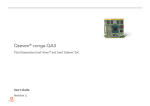
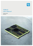
Qseven® conga-QMX6
Freescale® i.MX6 ARM® Cortex A9 processor with Ultra Low Power Consumption
User’s Guide
Revision 0.3 (Preliminary)
Revision History
Revision Date (yyyy.mm.dd) Author Changes
0.1
0.2
2013.03.28
2013.11.05
AEM
AEM
0.3
2014.02.28
AEM
• Preliminary release
• Corrected the LVDS data rates/resolutions supported in sections 2.1 “Feature List“ and 5.8 “LVDS”.
• Added information about the Atheros Quadcomm Ethernet PHY for conga-QMX6 revision B.0 in sections 2.1 “Feature List” and 5.3 “Gigabit
Ethernet”.
• Updated section 4 “Heatspreader”. Added additional heatspreader variants.
• Updated section 5.2 “UART”. Updated section 5.13 “Manufacturing/Jtag Interface”.
• Added pin descriptions for the onboard UART connector and the RS-232 adapter cable in section 10.1 “UART/RS-232 Debug Port”.
• Added section 10.3 “JTAG Interface”.
• Added the new Ethernet PHY (Qualcomm Atheros) for conga-QMX6 revision B.x to relevant sections.
• Changed the eMMC value of industrial variants from 2G to 4G
• Deleted the row “RSVD” from table 23 “ Manufacturing Signal Description”.
• Edited section 5.2 “UART” and added caution statement.
• Updated the whole document.
Copyright © 2013 congatec AG QMX6m03 2/63
Preface
This user’s guide provides information about the components, features, connectors and signals available on the conga-QMX6. It is one of four
documents that you should refer to when designing an i.MX6 based Qseven® application. The other reference documents that should be used
include the following:
Qseven® Design Guide
Qseven® Specification
i.MX6 Applications Processor Reference Manual (available at www.freescale.com)
The links to these documents can be found on the congatec AG website at www.congatec.com
Disclaimer
The information contained within this user’s guide, including but not limited to any product specification, is subject to change without notice.
congatec AG provides no warranty with regard to this user’s guide or any other information contained herein and hereby expressly disclaims
any implied warranties of merchantability or fitness for any particular purpose with regard to any of the foregoing. congatec AG assumes
no liability for any damages incurred directly or indirectly from any technical or typographical errors or omissions contained herein or for
discrepancies between the product and the user’s guide. In no event shall congatec AG be liable for any incidental, consequential, special, or
exemplary damages, whether based on tort, contract or otherwise, arising out of or in connection with this user’s guide or any other information
contained herein or the use thereof.
Intended Audience
This user’s guide is intended for technically qualified personnel. It is not intended for general audiences.
Copyright © 2013 congatec AG QMX6m03 3/63
Symbols
The following symbols are used in this user’s guide:
Warning
Warnings indicate conditions that, if not observed, can cause personal injury.
Caution
Cautions warn the user about how to prevent damage to hardware or loss of data.
Note
Notes call attention to important information that should be observed.
Copyright © 2013 congatec AG QMX6m03 4/63
Terminology
Term
PCI Express (PCIe)
ARM
JTAG
eCSPI
MIPI
GPIO
RGMII
PCI Express Lane
Description
Peripheral Component Interface Express – next-generation high speed Serialized I/O bus
Advanced RISC Machine
Joint Test Action Group
Enhanced Configurable Serial Peripheral Interface
Mobile Industry CPU Interface
General Purpose Input Output
Reduced Gigabit Media Independent Interface
One PCI Express Lane is a set of 4 signals that contains two differential lines for transmitting and two differential lines for Receiving. Clocking information is embedded
into the data stream.
x1, x2, x4, x8, x16
x1 refers to one PCI Express Lane of basic bandwidth; x2 to a collection of two PCI Express Lanes; etc.. Also referred to as x1, x2, x4, x8, or x16 link.
PCI Express Mini Card PCI Express Mini Card add-in card is a small size unique form factor optimized for mobile computing platforms.
eMMC
Embedded Multi Media Card is a non-volatile memory system, which frees the processor from low level flash memory management.
SDIO card
SDIO (Secure Digital Input Output) is a non-volatile memory card format developed for use in portable devices.
USB
Universal Serial Bus
SATA
Serial AT Attachment: serial-interface standard for hard disks
HDA
High Definition Audio
HDMI
High Definition Multimedia Interface. HDMI supports standard, enhanced, or high-definition video, plus multi-channel digital audio on a single cable.
TMDS
Transition Minimized Differential Signaling. TMDS is a signaling interface defined by Silicon Image that is used for DVI and HDMI.
DVI
Digital Visual Interface is a video interface standard developed by the Digital Display Working Group (DDWG).
I²C Bus
Inter-Integrated Circuit Bus: is a simple two-wire bus with a software-defined protocol that was developed to provide the communications link between integrated
circuits in a system.
SM Bus
System Management Bus: is a popular derivative of the I²C-bus.
SPI Bus
Serial Peripheral Interface is a synchronous serial data link standard named by Motorola that operates in full duplex mode.
CAN Bus
Controller-area network is a vehicle bus standard designed to allow microcontrollers and devices to communicate with each other within a vehicle without a host
computer.
AMBA
Advanced Microcontroller Bus Architecture
IOMUX
Input Output Multiplexer
GbE
Gigabit Ethernet
LVDS
Low-Voltage Differential Signaling
DDC
Display Data Channel is an I²C bus interface between a display and a graphics adapter.
N.C.
Not connected
N.A.
Not available
T.B.D.
To be determined
Copyright © 2013 congatec AG QMX6m03 5/63
Copyright Notice
Copyright © 2010, congatec AG. All rights reserved. All text, pictures and graphics are protected by copyrights. No copying is permitted without
written permission from congatec AG.
congatec AG has made every attempt to ensure that the information in this document is accurate yet the information contained within is
supplied “as-is”.
Trademarks
Product names, logos, brands, and other trademarks featured or referred to within this user’s guide, or the congatec website, are the property
of their respective trademark holders. These trademark holders are not affiliated with congatec AG, our products, or our website.
Warranty
congatec AG makes no representation, warranty or guaranty, express or implied regarding the products except its standard form of limited
warranty (“Limited Warranty”) per the terms and conditions of the congatec entity, which the product is delivered from. These terms and
conditions can be downloaded from www.congatec.com. congatec AG may in its sole discretion modify its Limited Warranty at any time and
from time to time.
The products may include software. Use of the software is subject to the terms and conditions set out in the respective owner’s license
agreements, which are available at www.congatec.com and/or upon request.
Beginning on the date of shipment to its direct customer and continuing for the published warranty period, congatec AG represents that the
products are new and warrants that each product failing to function properly under normal use, due to a defect in materials or workmanship or
due to non conformance to the agreed upon specifications, will be repaired or exchanged, at congatec’s option and expense.
Customer will obtain a Return Material Authorization (“RMA”) number from congatec AG prior to returning the non conforming product freight
prepaid. congatec AG will pay for transporting the repaired or exchanged product to the customer.
Repaired, replaced or exchanged product will be warranted for the repair warranty period in effect as of the date the repaired, exchanged
or replaced product is shipped by congatec, or the remainder of the original warranty, whichever is longer. This Limited Warranty extends to
congatec’s direct customer only and is not assignable or transferable.
Except as set forth in writing in the Limited Warranty, congatec makes no performance representations, warranties, or guarantees, either
express or implied, oral or written, with respect to the products, including without limitation any implied warranty (a) of merchantability, (b) of
fitness for a particular purpose, or (c) arising from course of performance, course of dealing, or usage of trade.
Copyright © 2013 congatec AG QMX6m03 6/63
congatec AG shall in no event be liable to the end user for collateral or consequential damages of any kind. congatec shall not otherwise be
liable for loss, damage or expense directly or indirectly arising from the use of the product or from any other cause. The sole and exclusive
remedy against congatec, whether a claim sound in contract, warranty, tort or any other legal theory, shall be repair or replacement of the
product only.
ISO 9001
Certification
congatec AG is certified to DIN EN ISO 9001:2008 standard.
C
ER
T I F I C AT I O
N
TM
Technical Support
congatec AG technicians and engineers are committed to providing the best possible technical support for our customers so that our products
can be easily used and implemented. We request that you first visit our website at www.congatec.com for the latest documentation, utilities and
drivers, which have been made available to assist you. If you still require assistance after visiting our website then contact our technical support
department by email at [email protected]
Lead-Free Designs (RoHS)
All congatec AG designs are created from lead‑free components and are completely RoHS compliant.
Electrostatic Sensitive Device
All congatec AG products are electrostatic sensitive devices and are packaged accordingly. Do not open or handle a congatec AG product
except at an electrostatic‑free workstation. Additionally, do not ship or store congatec AG products near strong electrostatic, electromagnetic,
magnetic, or radioactive fields unless the device is contained within its original manufacturer’s packaging. Be aware that failure to comply with
these guidelines will void the congatec AG Limited Warranty.
Copyright © 2013 congatec AG QMX6m03 7/63
Contents
1INTRODUCTION...................................................................... 11
5.3
Gigabit Ethernet........................................................................ 28
5.4SATA......................................................................................... 28
2
Specifications............................................................................ 13
5.5
USB 2.0..................................................................................... 28
5.6SD/SDIO/MMC.
......................................................................... 29
2.1
Feature List............................................................................... 13
5.7
HDA/I2S/AC’97.........................................................................
29
2.2
Supported Operating Systems.................................................. 14
5.8LVDS......................................................................................... 29
2.3
Mechanical Dimensions............................................................ 14
5.9
HDMI......................................................................................... 30
2.4
Supply Voltage Standard Power............................................... 15
5.10LPC/GPIO.................................................................................
30
2.4.1
Electrical Characteristics........................................................... 15
5.11SPI............................................................................................
31
2.4.2
Rise Time.................................................................................. 15
5.12
CAN Bus................................................................................... 31
2.5
Power Consumption.................................................................. 16
5.13
Manufacturing/JTAG Interface.................................................. 31
®
2.5.1Freescale i.MX6 Cortex A9 1.0 GHz Single Core 512kB L2 cache 5.14
Power Control........................................................................... 31
17
Power Management.................................................................. 33
2.5.2Freescale® i.MX6 Cortex A9 1.0 GHz Dual Lite 512kB L2 cache.17 5.15
5.16Watchdog..................................................................................
33
®
2.5.3Freescale i.MX6 Cortex A9 1.0 GHz Dual Core 1MB L2 cache.18
5.17
I2C
Bus.....................................................................................
34
®
2.5.4Freescale i.MX6 Cortex A9 1.0 GHz Quad Core 1MB L2 cache.18
2.5.5Freescale® i.MX6 Cortex A9 1.0 GHz Quad Core 1MB L2 cache.18 6
Additional Features................................................................... 35
2.5.6Freescale® i.MX6 Cortex A9 800 MHz Single Core 512kB L2
6.1
High Assurance Boot (HAB)...................................................... 35
cache (2GB eMMC).................................................................. 19
6.2
Dedicated Hardware Accelerators............................................ 35
®
2.5.7Freescale i.MX6 Cortex A9 800 MHz Dual Lite 512kB L2 cache
6.3
Power Management.................................................................. 35
(2GB eMMC)............................................................................. 19
6.4
Dynamic Voltage and Frequency Scaling................................. 35
2.5.8Freescale® i.MX6 Cortex A9 800 MHz Dual Core 1MB L2 cache
6.5
Smart Speed Technology.......................................................... 36
(2GB eMMC)............................................................................. 19
6.6
Suspend Mode.......................................................................... 36
2.5.9
Freescale® i.MX6 Cortex A9 800 MHz Quad Core 1MB L2 cache
(2GB eMMC)............................................................................. 20
7
ARM Technologies.................................................................... 37
2.6
Supply Voltage Battery Power.................................................. 20
7.1
Media Processing Engine (MPE-NEON) ................................. 37
2.6.1
CMOS Battery Power Consumption......................................... 20
7.2
Jazelle DBX.............................................................................. 37
2.7
Environmental Specifications.................................................... 21
7.3TrustZone.................................................................................. 37
3
Block Diagram........................................................................... 22
7.4
Floating Point Unit..................................................................... 37
4Heatspreader............................................................................ 23
4.1
Heatspreader Dimensions........................................................ 24
5
Connector Subsystems............................................................. 26
5.1
PCI Express™.......................................................................... 27
5.2UART/RS-232........................................................................... 27
8
conga Tech Notes..................................................................... 38
8.1Freescale® i.MX6 Processor Features...................................... 38
8.1.1
Temperature Monitor (TEMPMON)........................................... 38
8.2
Thermal Management............................................................... 38
8.3
Audio Mux................................................................................. 39
8.4
LVDS Bridge............................................................................. 39
Copyright © 2013 congatec AG QMX6m03 8/63
8.5
USB Port Connections.............................................................. 39
9
Interface - Signal Descriptions and Pinout Tables.................... 41
9.1
9.2
9.3
9.4
9.5
9.6
9.7
9.8
9.9
9.10
9.11
9.12
9.13
9.14
9.15
9.16
9.17
9.18
9.19
9.20
9.21
PCI Express™.......................................................................... 45
UART........................................................................................ 45
Gigabit Ethernet........................................................................ 46
SATA......................................................................................... 47
USB 2.0..................................................................................... 47
SDIO/MMC................................................................................ 49
HDA /I2S /SPDIF....................................................................... 50
LVDS......................................................................................... 50
DisplayPort................................................................................ 52
HDMI......................................................................................... 52
LPC/GPIO................................................................................. 53
SPI............................................................................................ 54
CAN Bus................................................................................... 54
Input Power............................................................................... 54
Power Control........................................................................... 55
Power Management.................................................................. 55
Miscellaneous........................................................................... 56
Manufacturing/JTAG Interface.................................................. 57
Thermal Management............................................................... 58
Fan Control............................................................................... 58
Bootstrap Signals...................................................................... 59
10
Onboard Interfaces and Devices.............................................. 60
10.1
UART/RS-232 Debug Port........................................................ 60
10.2
MIPI/CMOS Camera................................................................. 60
10.3
JTAG Interface.......................................................................... 61
10.4
SPI Flash.................................................................................. 61
10.5
Android Buttons........................................................................ 61
10.6
DDR3 Memory.......................................................................... 61
10.7eMMC....................................................................................... 62
10.8
Micro SD................................................................................... 62
11
Industry Specifications.............................................................. 63
Copyright © 2013 congatec AG QMX6m03 9/63
List of Tables
Table 1
Table 2
Table 3
Table 4
Table 5
Table 6
Table 7
Table 8
Table 9
Table 10
Table 11
Table 12
Table 13
Table 14
Table 15
Table 16
Table 17
Table 18
Table 19
Table 20
Table 21
Table 22
Table 23
Table 24
Table 25
Table 26
Table 27
Table 28
Commercial variants................................................................. 12
Industrial Variants..................................................................... 12
Feature Summary..................................................................... 13
Signal Tables Terminology Descriptions................................... 41
Edge Finger Pinout................................................................... 42
PCI Express Signal Descriptions.............................................. 45
UART Signal Descriptions........................................................ 45
Ethernet Signal Descriptions..................................................... 46
SATA Signal Descriptions......................................................... 47
USB Signal Descriptions........................................................... 47
SDIO Signal Descriptions......................................................... 49
HDA/AC’97 Signal Descriptions................................................ 50
LVDS Signal Descriptions......................................................... 50
DisplayPort Signal Descriptions................................................ 52
HDMI Signal Descriptions......................................................... 52
LPC/GPIO Signal Descriptions................................................. 53
SPI Interface Signal Descriptions............................................. 54
CAN Bus Signal Descriptions................................................... 54
Input Power Signal Descriptions............................................... 54
Power Control Signal Descriptions........................................... 55
Power Management Signal Descriptions.................................. 55
Miscellaneous Signal Descriptions........................................... 56
Manufacturing Signal Descriptions........................................... 57
Thermal Management Signal Descriptions............................... 58
Fan Control Signal Descriptions............................................... 58
Bootstrap Signal Descriptions................................................... 59
UART Signal Descriptions........................................................ 60
Android Button Signal Descriptions.......................................... 61
Copyright © 2013 congatec AG QMX6m03 10/63
1
INTRODUCTION
Qseven® Concept
The Qseven® concept is an off-the-shelf, multi vendor, Single-Board-Computer that integrates all the core components of a common PC and is
mounted onto an application specific carrier board. Qseven® modules have a standardized form factor of 70mm x 70mm and a specified pinout
based on the high speed MXM system connector. The pinout remains the same regardless of the vendor. The Qseven® module provides the
functional requirements for an embedded application. These functions include, but are not limited to graphics, sound, mass storage, network
interface and multiple USB ports.
A single ruggedized MXM connector provides the carrier board interface to carry all the I/O signals to and from the Qseven® module. This MXM
connector is a well known and proven high speed signal interface connector that is commonly used for high speed PCI Express graphics cards
in notebooks.
Carrier board designers can utilize as little or as many of the I/O interfaces as deemed necessary. The carrier board can therefore provide all
the interface connectors required to attach the system to the application specific peripherals. This versatility allows the designer to create a
dense and optimized package, which results in a more reliable product while simplifying system integration.
The Qseven® evaluation carrier board provides carrier board designers with a reference design platform and the opportunity to test all the
Qseven® I/O interfaces available and then choose what are suitable for their application. Qseven® applications are scalable, which means once
a carrier board has been created there is the ability to diversify the product range through the use of different performance class Qseven®
modules. Simply unplug one module and replace it with another; no need to redesign the carrier board.
This document describes the features available on the Qseven® evaluation carrier board. Additionally, the schematics for the Qseven® evaluation
carrier board can be found on the congatec website.
Note
The conga-QMX6 design is based on the Qseven specification 2.0 and in revision B.0 design, we took into consideration the Qseven Specification
2.0 Errata.
Copyright © 2013 congatec AG QMX6m03 11/63
conga-QMX6 Options Information
The conga-QMX6 is currently available in nine variants (five commercial and four industrial). This user’s guide describes the features these
variants offer. Below you will find an order table showing the base configuration modules that are currently offered by congatec AG. For more
information about additional conga-QMX6 variants offered by congatec, contact your local congatec sales representative or visit the congatec
website at www.congatec.com.
Table 1
Commercial variants
Part-No.
016100
Processor
L2 Cache
Onboard Memory
eMMC up to 8GB
PCI Express Lane
CAN Bus
Gigabit Ethernet
SATA
Table 2
016101
016102
016103
016104
Freescale i.MX6 Cortex A9 Freescale i.MX6 Cortex A9 Freescale i.MX6 Cortex A9 Freescale i.MX6 Cortex A9 Freescale® i.MX6 Cortex A9
1.0 GHz Single Core
1.0 GHz Dual Lite
1.0 GHz Dual Core
1.0 GHz Quad Core
1.0 GHz Quad Core
512 kB
512 kB
1 MB
1 MB
1 MB
1GB DDR3
1GB DDR3
1GB DDR3
1GB DDR3
2GB DDR3
4GB
4GB
4GB
4GB
4GB
Yes
Yes
Yes
Yes
Yes
Yes
Yes
Yes
Yes
Yes
Yes
Yes
Yes
Yes
Yes
No
No
Yes
Yes
Yes
®
®
016110
016111
®
®
Industrial Variants
Part-No.
Processor
L2 Cache
Onboard Memory
eMMC up to 8GB
PCI Express Lane
CAN Bus
Gigabit Ethernet
SATA
016112
Freescale® i.MX6 Cortex A9 Freescale® i.MX6 Cortex A9 Freescale® i.MX6 Cortex A9
800 MHz Single Core
800 MHz Dual Lite
800 MHz Dual Core
512 kB
512 kB
1 MB
1GB DDR3
1GB DDR3
1GB DDR3
4GB
4GB
4GB
Yes
Yes
Yes
Yes
Yes
Yes
Yes
Yes
Yes
No
No
Yes
016113
Freescale® i.MX6 Cortex A9
800 MHz Quad Core
1 MB
1GB DDR3
4GB
Yes
Yes
Yes
Yes
Caution
Do not alter the conga-QMX6 boot fuse settings. These fuse settings are already programmed during production process and are not protected
against alteration. Changing the boot fuse settings will void the congatec AG warranty.
Copyright © 2013 congatec AG QMX6m03 12/63
2
Specifications
2.1
Feature List
Table 3
Feature Summary
Form Factor
Processor
Memory
Audio
Ethernet
Graphics Options
Based on Qseven® form factor specification revision 2.0
Freescale® i.MX6 Cortex A9
up to 2 GB onboard DDR3 memory
I2S format supported
Gigabit Ethernet (Qualcomm Atheros PHY) on conga-QMX6 rev B.x. Earlier conga-QMX6 variants are equipped with Micrel KSZ9031 PHY.
Integrated video graphic subsystem consisting of Video Processing Unit (VPU), Graphic Processing Unit (3D GPU, 2D GPU, Open VG), Image
Processing Unit, Display interface bridges (LVDS, HDMI, MIPI/DSI).
• 1x HDMI 1.4.
• Two LVDS channels driven by the LVDS display bridge. Support:
• Single channel LVDS interface : 1 x 18 bpp or 1 x 24 bpp (up to 85 MHz per
interface e.g 1366x768 @ 60Hz + 35% blanking)
• Dual channel LVDS interface: 2 x 18 bpp OR 2 x 24 bpp (up to 170 MHz pixel
clock e.g 1600x1200 @ 60 Hz + 35% blanking).
NOTE:
Supports three independent displays (must be 2x single channel LVDS and 1x HDMI)
• 1x Serial ATA® Gen 2 (3GB/s)
Peripheral
• 1x SDIO
Interfaces
• x1 PCI Express Lane Gen 2.0 offering up to 5 GB/s
• 5x USB 2.0 ports (4x USB 2.0 hosts and 1x USB 2.0 OTG)
• I2S Bus
• SPI
• CAN
Onboard Interfaces • Android Buttons
• JTAG
and Devices
• RS-232 Debug Port
• SPI Flash (contains the bootloader)
Pre-installed open-source bootloader (U-boot)
Bootloader
Power Management Yes.
• Video Decode Acceleration:
MPEG2 MP, HP
MPEG4 SP
H.264
VC-1
DivX
• 8x GPIOs
• 3x I²C fast mode, multi-master (two shared I²C buses and
one unshared bus)
• 1x UART (fully featured UART with control signals,
supported on the MXM connector)
• 2x RS-232 interfaces supported onboard the conga-QMX6
via RS232 transceiver.
• DDR3 SDRAM memory (up to 2 GB)
• Micro-SD Socket
• eMMC module (4GB onboard)
Note
Some of the features mentioned in the above feature summary are optional. Check the article number of your module and compare it to the
conga-QMX6 options information list on page 12 of this user’s guide to determine what options are available on your particular module.
Copyright © 2013 congatec AG QMX6m03 13/63
2.2
Supported Operating Systems
The conga-QMX6 supports the following operating systems.
• Microsoft® Windows® Embedded Compact 7
• Android
• Linux
2.3
Mechanical Dimensions
• 70.0 mm x 70.0 mm @ (2 ¾” x 2 ¾”)
• The Qseven™ module, including the heatspreader plate, PCB thickness and bottom components, is up to approximately 12mm thick.
Heatspeader
Qseven Module PCB
2.00
8.00
6.00
Dimension is dependent
on connector height used
Dimension is dependent
on connector height used
1.20 ±0.1
All measurements are in millimeters
All dimensions without tolerance ±0.2mm
Carrier Board PCB
Rear View of Qseven Module
Copyright © 2013 congatec AG QMX6m03 14/63
2.4
Supply Voltage Standard Power
• 5V DC ± 5%
The dynamic range shall not exceed the static range.
5.25V
Absolute Maximum
Dynamic Range
5.05V
5V
Nominal
Static Range
4.95V
4.75V
2.4.1
Electrical Characteristics
Characteristics
5V
5V_SB
2.4.2
Absolute Minimum
Voltage
Ripple
Current
Voltage
Ripple
± 5%
± 5%
Min.
4.75
-
4.75
Typ.
5.00
-
5.00
Max.
5.25
± 50
5.25
± 50
Units
Vdc
mVPP
Comment
0-20MHz
Vdc
mVPP
Rise Time
The input voltages shall rise from 10% of nominal to 90% of nominal at a minimum slope of 250V/s. The smooth turn-on requires that during
the 10% to 90% portion of the rise time, the slope of the turn-on waveform must be positive.
Note
For information about the input power sequencing of the Qseven® module, refer to the Qseven® specification.
Copyright © 2013 congatec AG QMX6m03 15/63
2.5
Power Consumption
The power consumption values listed in this document were measured under a controlled environment. The hardware used for testing includes
a conga-QMX6 module, carrier board for Qseven ARM, TFT monitor, micro-SD card and USB keyboard. The carrier board was powered
externally by a power supply unit so that it does not influence the power consumption value that is measured for the module. The USB keyboard
was detached once the module was configured within the OS. All recorded values were averaged over a 30 second time period. The modules
were cooled by the heatspreader specific to the module variants
Each module was measured while running 32 bit Linaro Ubuntu 11.10. To measure the worst case power consumption, the cooling solution
was removed and the CPU core temperature was allowed to run between 95° and 100°C at 100% workload. The peak current value was then
recorded. This value should be taken into consideration when designing the system’s power supply to ensure that the power supply is sufficient
during worst case scenarios.
Power consumption values were recorded during the following stages:
Linaro Ubuntu 11.10 (32 bit)
• Desktop Idle
• 100% CPU workload
• 100% CPU workload at approximately 100°C peak power consumption
Note
With the linux stress tool, we stressed the CPU to maximum frequency.
Copyright © 2013 congatec AG QMX6m03 16/63
Processor Information
The tables below provide additional information about the different variants offered by the conga-QMX6.
2.5.1
Freescale® i.MX6 Cortex A9 1.0 GHz Single Core 512kB L2 cache
With 4GB onboard eMMC
conga-QMX6 Art. No. 016100
Memory Size
Operating System
Power State
Power consumption (measured in Amperes/Watts)
2.5.2
Freescale® i.MX6 Cortex A9 1.0 GHz 512kB L2 cache
40nm
Layout Rev. QMX6LB1 /Bootloader Rev. QMX6Rx07
1GB onboard
Ubuntu
Desktop Idle
0.22 A/ 1.1 W
100% workload
0.34 A/ 1.7 W
Max. Power Consumption
0.46 A/2.3 W
Freescale® i.MX6 Cortex A9 1.0 GHz Dual Lite 512kB L2 cache
With 4GB onboard eMMC
conga-QMX6 Art. No. 016101
Memory Size
Operating System
Power State
Power consumption (measured in Amperes/Watts)
Freescale® i.MX6 Cortex A9 1.0 GHz 512kB L2 cache
40nm
Layout Rev. QMX6LB1 /Bootloader Rev. QMX6Rx07
1GB onboard
Ubuntu
Desktop Idle
0.26 A/ 1.3 W
100% workload
0.44 A/ 2.2 W
Max. Power Consumption
0.66 A/ 3.3 W
Copyright © 2013 congatec AG QMX6m03 17/63
2.5.3
Freescale® i.MX6 Cortex A9 1.0 GHz Dual Core 1MB L2 cache
With 4GB onboard eMMC
conga-QMX6 Art. No. 016102
Memory Size
Operating System
Power State
Power consumption (measured in Amperes/Watts)
2.5.4
1GB onboard
Ubuntu
Freescale® i.MX6 Cortex A9 1.0 GHz 1MB L2 cache
40nm
Layout Rev. QMX6LB1 /Bootloader Rev. QMX6Rx07
Desktop Idle
0.28 A/ 1.4 W
100% workload
0.5 A/ 2.5 W
Max. Power Consumption
0.7 A/ 3.2 W
Freescale® i.MX6 Cortex A9 1.0 GHz Quad Core 1MB L2 cache
With 4GB onboard eMMC
conga-QMX6 Art. No. 016103
Memory Size
Operating System
Power State
Power consumption (measured in Amperes/Watts)
2.5.5
1GB onboard
Ubuntu
Freescale® i.MX6 Cortex A9 1.0 GHz 1MB L2 cache
40nm
Layout Rev. QMX6LB1 /Bootloader Rev. QMX6Rx07
Desktop Idle
0.3 A/ 1.5 W
100% workload
0.72 A/ 3.6 W
Max. Power Consumption
0.92 A/ 4.6 W
Freescale® i.MX6 Cortex A9 1.0 GHz Quad Core 1MB L2 cache
With 4GB onboard eMMC
conga-QMX6 Art. No. 016104
Memory Size
Operating System
Power State
Power consumption (measured in Amperes/Watts)
2GB onboard
Ubuntu
Freescale® i.MX6 Cortex A9 1.0 GHz 1MB L2 cache
40nm
Layout Rev. QMX6LB1 /Bootloader Rev. QMX6Rx07
Desktop Idle
0.3 A/ 1.5 W
100% workload
0.74 A/ 3.7 W
Max. Power Consumption
0.94 A/ 4.7 W
Copyright © 2013 congatec AG QMX6m03 18/63
2.5.6
Freescale® i.MX6 Cortex A9 800 MHz Single Core 512kB L2 cache (2GB eMMC)
With 2GB onboard eMMC
conga-QMX6 Art. No. 016110
Memory Size
Operating System
Power State
Power consumption (measured in Amperes/Watts)
2.5.7
Freescale® i.MX6 Cortex A9 800 MHz 512kB L2 cache
40nm
Layout Rev. QMX6LB1 /Bootloader Rev. QMX6Rx07
1GB onboard
Ubuntu
Desktop Idle
0.24 A/ 1.2 W
100% workload
0.30 A/ 1.5 W
Max. Power Consumption
0.48 A/ 2.1 W
Freescale® i.MX6 Cortex A9 800 MHz Dual Lite 512kB L2 cache (2GB eMMC)
With 2GB onboard eMMC
conga-QMX6 Art. No. 016111
Memory Size
Operating System
Power State
Power consumption (measured in Amperes/Watts)
2.5.8
Freescale® i.MX6 Cortex A9 800 MHz 512kB L2 cache
40nm
Layout Rev. QMX6LB1 /Bootloader Rev. QMX6Rx07
1GB onboard
Ubuntu
Desktop Idle
TBD A/ W
100% workload
TBD A/ W
Max. Power Consumption
TBD A/ W
Freescale® i.MX6 Cortex A9 800 MHz Dual Core 1MB L2 cache (2GB eMMC)
With 2GB onboard eMMC
conga-QMX6 Art. No. 016112
Memory Size
Operating System
Power State
Power consumption (measured in Amperes/Watts)
1GB onboard
Ubuntu
Freescale® i.MX6 Cortex A9 800 MHz 1MB L2 cache
40nm
Layout Rev. QMX6LB1 /Bootloader Rev. QMX6Rx07
Desktop Idle
0.30 A/ 1.5W
100% workload
0.42 A/ 2.1 W
Max. Power Consumption
0.60 A/ 3.0 W
Copyright © 2013 congatec AG QMX6m03 19/63
2.5.9
Freescale® i.MX6 Cortex A9 800 MHz Quad Core 1MB L2 cache (2GB eMMC)
With 2GB onboard eMMC
conga-QMX6 Art. No. 016113
Memory Size
Operating System
Power State
Power consumption (measured in Amperes/Watts)
1GB onboard
Ubuntu
Freescale® i.MX6 Cortex A9 800 MHz 1MB L2 cache
40nm
Layout Rev. QMX6LB1 /Bootloader Rev. QMX6Rx07
Desktop Idle
0.30 A/ 1.5 W
100% workload
0.54 A/ 2.7 W
Max. Power Consumption
0.72 A/ 3.6 W
Note
All recorded power consumption values are approximate and only valid for the controlled environment described earlier. 100% workload refers
to the CPU workload and not the maximum workload of the complete module. Power consumption results will vary depending on the workload
of other components such as graphics engine, memory, etc.
2.6
Supply Voltage Battery Power
• 2.0V-3.6V DC
• Typical 3V DC
2.6.1
CMOS Battery Power Consumption
RTC @ 20ºC
RTC onboard the conga-QMX6 module
Voltage
3V DC
Current
1.45 µA
The CMOS battery power consumption value listed above should not be used to calculate CMOS battery lifetime. You should measure the
CMOS battery power consumption in your customer specific application in worst case conditions, for example during high temperature and
high battery voltage. The self-discharge of the battery must also be considered when determining CMOS battery lifetime. For more information
about calculating CMOS battery lifetime refer to application note AN9_RTC_Battery_Lifetime.pdf, which can be found on the congatec AG
website at www.congatec.com.
Note
To improve the lifetime of the CMOS battery, congatec implemented an external real time clock onboard the conga-QMX6 module.
Copyright © 2013 congatec AG QMX6m03 20/63
2.7
Environmental Specifications
Temperature
Operation: 0° to 60°C
Storage: -20° to +80°C (commercial grade variants of conga-QMX6)
Temperature
Operation: -40° to 85°C
Storage: -40° to +85°C (industrial grade variants of conga-QMX6)
Humidity
Operation: 10% to 90%
Storage: 5% to 95% (humidity specifications are for non-condensing conditions)
Caution
The above operating temperatures must be strictly adhered to at all times. The congatec heatspreader is only suitable for use within commercial
temperature ranges (0° to 60°C), it is not designed to be used within industrial temperature ranges (-40° to 85°C). When using a heatspreader
with conga-QMX6 commercial grade variants, the maximum operating temperature refers to any measurable spot on the heatspreader’s
surface.
congatec AG strongly recommends that you use the appropriate congatec module heatspreader as a thermal interface between the module
and your application specific cooling solution when used in a commercial temperature range.
If it is not possible to use the appropriate congatec module heatspreader for conga-QMX6 commercial grade variants, or an industrial grade
variant of conga-QMX6 is being used within industrial temperature ranges, then it is the responsibility of the operator to ensure that all
components found on the module operate within the component manufacturer’s specified temperature range.
Copyright © 2013 congatec AG QMX6m03 21/63
3
Block Diagram
Qseven
Connector
230 pin goldfinger
Power Rail
PMIC
Power
BATT
Freescale
PFUZE100
Control I2C2/3
CPU Platform
32 KB D-Cache
per Core
32 KB I-Cache
per Core
HDMI
UART0
10/100/1G Eth
RGMII
Micrel
KSZ9031
UART3
Video Codecs
1080p30 Enc/Dec
Audio
ASRC
SPI
RS232
Debug Port
onboard
I2C Bus
I2S Audio
UART1
MAXIM
MAX3232
Imaging Processing Unit
Resizing and Blending
Image Enhancement
Inversion/Rotation
USB H1
USB-Hub
SMSC
USB2514
USB OTG
LVDS single/dual channel
SD4 8bit
SD3 8bit
JTAG
MFG_NC0...4
USB Port 0
USB Port 2
USB Port 3
USB Port 4
USB Port 1 / Client
LVDS
SDIO
eMMC
max. 16GB BGA
onboard
Display and Camera Interface
Dual 24-bit LVDS
I2C1
HDMI and PHY
I2S / SPDIF
MIPI CSI2
3-axis ACC
freescale
MMA8450Q
PCIE0
UART2
Debug Port
onboard
256 KB–1 MB L2-Cache
Multimedia
Hardware Graphics Accelerators
3D
Vector Graphics
2D
HDMI
JTAG/TRACE JTAG/TRACE
PTM per Core
NEON per Core
Gigabit
Transceiver
(2G DDR3L SDRAM 256MX16)
DDR3
ARM ® Cortex™ -A9 Core
Gigabit Ethernet
DDR3 onboard Memory
freescale i.MX6 Cortex A9
Qseven
Connector
230 pin goldfinger
SD2 4bit
Int. Memory
I2C2
ROM
RAM
PCIe
Micro SD
socket
onboard
Security
RNG
Security Cntrl.
TrustZone
Secure RTC
Ciphers
eFuses
FlexCAN
SATA
CAN-Bus
SATA Port 0
NOTE:
The conga-QMX6 BSPs do no currently
support the camera interface.
Feature Connector
MIPI/CMOS camera
SPI Flash
onboard
Android Buttons
onboard connector
Copyright © 2013 congatec AG QMX6m03 22/63
4
Heatspreader
Thermal design is an important factor for systems. This factor is critical when the power dissipation level increases in certain high performance
use cases. To ensure the performance and reliability of the system, adequate thermal management technique such as the heatspreader is
necessary.
The heatspreader acts as a thermal coupling device to the module. It is thermally coupled to the CPU via a thermal gap filler and on some
modules, it may also be thermally coupled to other heat generating components with the use of additional thermal gap fillers. Although the
heatspreader is the thermal interface where most of the heat generated by the module is dissipated, it is not to be considered as a heatsink. It
has been designed as a thermal interface between the module and the application specific thermal solution.
The application specific thermal solution may use heatsinks with fans, and/or heat pipes, which can be attached to the heatspreader. Some
thermal solutions may also require that the heatspreader is attached directly to the systems chassis thereby using the whole chassis as a heat
dissipater.
congatec AG offers three heatspreader variants for the conga-QMX6. Each heatspreader variant is intended for specific conga-QMX6 modules
as shown in the table below:
Heatspreader
Variants
conga-QMX6/HSP1-B
conga-QMX6/HSP2-B
conga-QMX6/HSP3-B
Heatspreader
Part No. (PN)
016160
016161
016162
Compatible conga-QMX6
Variants (PN)
016112, 016113
016100, 016101, 016110, 016111
016102, 016103, 016104
Comment
For modules equipped with lidded FC-PBGA CPU (1mm Gap Pad)
For modules equipped with MA-PBGA CPU (2mm Gap Pad)
For modules equipped with non-lidded FC-PBGA CPU (heatstack solution)
Note
Currently, only a few Freescale® iMX6 on-chip devices are enabled by default in the bootloader. With this default configuration, the conga-QMX6
power consumption is low. However, power consumption may increase significantly depending on the application and the workload of the CPU.
Caution
congatec Qseven® heaspreaders have been specifically designed for use within commercial temperature ranges (0° to 60°C) only. When using
industrial temperature variants of the conga-QMX6 in industrial temperature ranges (-40° to 85°C), use of the conga-QMX6 heatspreaders is
not recommended by congatec; furthermore, its use is at the risk of the end user. It is the responsibility of the end user to design an optimized
thermal solution that meets the needs of their application within the industrial environmental conditions it operates in.
There are mounting holes on the heatspreader designed to attach the heatspreader to the module. These mounting holes must be used to
ensure that all components that are required to make contact with heatspreader do so. Failure to utilize these mounting holes will result in
improper contact between these components and heatspreader thereby reducing heat dissipation efficiency.
Copyright © 2013 congatec AG QMX6m03 23/63
Attention must be given to the mounting solution used to mount the heatspreader and module into the system chassis. Do not use a threaded
heatspreader together with threaded carrier board standoffs. The combination of the two threads may be staggered, which could lead to
stripping or cross-threading of the threads in either the standoffs of the heatspreader or carrier board.
4.1
Heatspreader Dimensions
conga-QMX6/HSP1-B and HSP2-B
0
3
67
1mm for conga-QMX6/HSP1-B
2mm for conga-QMX6/HSP2-B
R0
.2
65
X-X
X
2.5
.2
R0
8 ±0.1
65
56.5
R1
0.8
49
c
f
0.2
0.1 A
A
5.5 ±0.1
R1
20
2.5
.2
2.5
D (5:1)
R1
0
90°
4.5
R0
.2
X
0.2
8 ±0.1
70
52
18
0
R0
.2
0
D
ø2.7
R0
0.8
27
0.25 x45°(4x)
1
ø5
29
Copyright © 2013 congatec AG QMX6m03 24/63
conga-QMX6/HSP3-B
Note
All measurements are in millimeters. Torque specification for heatspreader screws is 0.3 Nm. Mechanical system assembly mounting shall
follow the valid DIN/IS0 specifications.
Caution
When using the heatspreader in a high shock and/or vibration environment, congatec recommends the use of a thread-locking fluid on the
heatspreader screws to ensure the above mentioned torque specification is maintained.
Copyright © 2013 congatec AG QMX6m03 25/63
5
Connector Subsystems
The conga-QMX6 is based on the Qseven® standard and therefore has 115 edge fingers on the top and bottom side of the module that mate
with the 230-pin card-edge MXM connector located on the carrier board. This connector provides the ability to interface the available signals of
the conga-QMX6 with the carrier board peripherals.
1x PCI Express Lane
UART
onboard RS-232
Gigabit Ethernet
1x Serial ATA
4x USB 2.0
1x USB OTG
SDIO/MMC/MicroSD
I²S Audio
LVDS
1x HDMI
GPIO
SPI
CAN Bus
JTAG
Power Control
Power Management
Watchdog
I²C Bus
Copyright © 2013 congatec AG QMX6m03 26/63
5.1
PCI Express™
The conga-QMX6 offers one PCI Express lane. The PCIe signals are routed from the Freescale® i.MX6 processor to the PCI Express port 0
of the conga-QMX6 edge finger. These signals support PCI Express Gen. 2.0 interfaces at 5 Gb/s and are backward compatible to Gen. 1.1
interfaces at 2.5 Gb/s. Only x1 PCI Express link configuration is possible.
For more information about the PCI Express interface on the edge finger, refer to the conga‑QMX6 pinout table in section 9 “Interface - Signal
Descriptions and Pinout Tables.”
5.2
UART/RS-232
The conga-QMX6 offers one UART interface on the MXM connector and two RS-232 interfaces onboard. The UART offered on the MXM
connector is fully featured with control signals (4 pin UART) and is connected directly to UART3 port of the Freescale® i.MX6 Cortex A9
processor.
The conga-QMX6 offers the two onboard RS-232 interfaces via a 6-pin Molex connector. This connector is provided by routing the UART2
and UART5 pins of the Freescale® i.MX6 processor to the MAXIM-3232 transceiver. The transceiver converts the Qseven® UART CMOS level
(3.3V) to RS-232 voltage levels (5v) and is guaranteed to run at data rates of 250 kbps in the normal operating mode, while maintaining RS-232
output levels. With the Molex connector, you can output data to the console by using the appropriate RS-232 adapter cable.
The UART interfaces support speeds up to 4.0 Mbps and Non-Return-To-Zero encording format, RS-485 compatible 9 bit data format and IrDA
compatible infrared slow data rate format.
Note
You can realize a second UART interface on the MFG interface. This implementation however requires a customized conga-QMX6 variant.
Contact congatec support for more information.
To display the u-boot output to console, you need the RS232 adapter cable (PN: 48000023). See section 10.1 “UART/RS-232 Debug Port” for
more information about the RS232 adapter cable and the UART pin description.
Caution
The MFG_NC4 pin is high active on the conga-QMX6 module. This means that the MFG interface on the edge connector functions as JTAG
interface by default. Therefore, do not use the MFG interface for UART purposes or externally pull the MFG_NC4 pin to ground. Failure to
adhere to this warning may result to back-driving which can damage the module.
If you need the UART function on the MFG interface, then you require a customized conga-QMX6. For more information, contact congatec support.
Copyright © 2013 congatec AG QMX6m03 27/63
5.3
Gigabit Ethernet
The conga-QMX6 rev B.x offers Gigabit Ethernet with the integration of Qualcomm Atheros Gigabit Transceiver. This transceiver is implemented
via the RGMII interface of the i.MX6 processor. The Ethernet interface consists of 4 pairs of low voltage differential pair signals designated from
GBE0_MDI0± to GBE0_MDI3± plus control signals for link activity indicators. These signals can be used to connect to a 10/100/1000 BaseT
RJ45 connector with integrated or external isolation magnetics on the carrier board.
Earlier conga-QMX6 revisions offer Gigabit Ethernet with the integration of Micrel KSZ 9031 Ethernet PHY.
Note
The theoretical maximum performance of 1 Gbps Ethernet is limited to 470 Mbps (total for Tx and Rx) due to internal bus throughput limitations.
The actual measured performance in optimized environment is up to 400 Mbps. For more information, consult Freescale’s Errata ERR004512.
Some signals have special functionality during the reset process. They may bootstrap some basic important functions of the module. For more
information, refer to section 9.21 of this user’s guide.
5.4
SATA
The Freescale® i.MX6 Cortex A9 processor on the conga-QMX6 supports one SATA port only. The supported signals are coupled with 10nF
capacitors and then routed to conga-QMX6 edge finger. The conga-QMX6 offers this SATA port on the MXM connector. This port supports
SATA I (1.5Gbps) and SATA II (3Gbps) and is compliant with SATA specification 3.0, AHCI specification 1.3 and Advanced Microcontroller Bus
Architecture (AMBA) specification 2.0.
Note
SATA interface is only supported on conga-QMX6 quad and dual core variants. Solo core and dual lite variants do not support SATA.
5.5
USB 2.0
The conga-QMX6 offers five USB ports via USB 2.0 host controllers provided by the Freescale® i.MX6 Cortex A9 processor. These controllers
provide high performance USB functionality that complies with USB 2.0 specification and with OTG supplement.
The offered ports comprise of one USB OTG port and four USB hosts. These four USB hosts are derived through the integration of an SMSC
USB hub, and are implemented by routing the USB H1 port of the processor to the SMSC Hub. The USB OTG port (OTG client) is connected
directly to the USB_OTG port of the i.MX6 processor.
The OTG client port can drop the hosting role and act as a normal USB device when conga-QMX6 is attached to another host. The direction
Copyright © 2013 congatec AG QMX6m03 28/63
of OTG port depends on the USB control signal (USB_ID). If asserted high, the OTG is set to client and if low, the OTG port is set to host. All
ports are capable of supporting USB 1.1 and 2.0 compliant devices.
5.6
SD/SDIO/MMC
SDIO stands for Secure Digital Input Output. Devices that support SDIO can use small devices such as SD-Card or MMC-Card flash memories.
The SD/SDIO/MMC cards communicate with the host system via the Ultra Secured Digital Host Controller (uSDHC). This controller acts as
a bridge by sending commands and accessing data to and from the cards. The Freescale® i.MX6 processor on the conga-QMX6 provides
SD/SDIO/MMC controllers (SD1-SD4) for communicating with different SD, SDIO and MMC devices.
The conga-QMX6 offers one SDIO interface on the MXM connector via the Freescale® i.MX6 SD4 port. Two other SDIO ports provided by the
Freescale® i.MX6 processor are supported onboard the conga-QMX6. These ports (SD2 and SD3) connect the onboard 4 bit micro SD and the
onboard 8 bit eMMC respectively
The SDIO ports support SDIO Revision 1.1, SD Memory Card Specification Revision 3.0 and MMC Revision 4.4.
5.7
HDA/I2S/AC’97
The conga-QMX6 uses the I2S format for audio signals. These signals are derived from the Synchronous Serial Interface (SSI) of the Freescale®
i.MX6 processor. The SSI is a full duplex serial port that allows communication with external devices using a variety of serial protocols. The I2S
protocol is part of the protocols supported by the Freescale® i.MX6 Cortex A9 processor. The SSI supports up to 1.4 Mbps.
Note
The conga-QMX6 currently supports only I2S format.
5.8
LVDS
The LVDS Display Bridge (LDB) from the Freescale® i.MX6 Cortex A9 processor found on the conga-QMX6 offers two LVDS channels, with up
to 170 Mhz pixel clock. Each channel consists of one clock pair and four data pairs. The LDB supports the flow of synchronous RGB data from
the Image Processing Unit (IPU) to external display devices through LVDS interface.
The LVDS interface supports 18 bit and 24 bit dual channel. The LVDS interface also supports various resolutions but with stipulated maximum
data rates. The data rates supported are as follows:
For single channel output: Up to 85 MHz per interface (e.g 1366x768 @ 60 Hz + 35 % blanking).
Copyright © 2013 congatec AG QMX6m03 29/63
For dual channel output: Up to 170 MHz pixel clock (e.g 1600x1200 @ 60Hz + 35 % blanking)
The LVDS ports support the following configurations:
• One single channel output
• One dual channel output: single input split to two output channels
• Two identical outputs: single input sent to both output channels
• Two independent outputs: two inputs sent, each to a different output channel
Note
The LVDS interface can be used either as a single channel or as a dual channel. It is also possible to use the LVDS interface as two independent
single LVDS channels. To do this, it is recommended to configure the LVDS display in the bootloader.
Three independent displays are possible when connected as two single LVDS channel and one HDMI interface.
5.9
HDMI
High-Definition Multimedia Interface (HDMI) is a licensable compact audio/video connector interface for transmitting uncompressed digital
streams. HDMI encodes the video data into TMDS for digital transmission and is backward-compatible with the single-link Digital Visual
Interface (DVI) carrying digital video.
The conga-QMX6 provides HDMI connection directly from the Freescale® i.MX6 processor. Video data is provided through three differential
TMDS data pairs (TMDS_LANE0± to TMDS_LANE2±) and one differential clock pair (TMDS_CLK±). In addition, the conga-QMX6 includes
one standard I2C interface (I2C2_SDA and I2C2_SCL) for configuring and testing the HDMI 3D Tx PHY and a pin (DP_HDMI_HPD) for HDMI
hot plug detection support.
5.10
LPC/GPIO
The conga-QMX6 does not support the Low Pin Count (LPC) signals, instead eight GPIO pins shared with the LPC pins according to Qseven
specification 2.0 are supported.
The General Purpose Input/Output pins can be configured as inputs or outputs. When configured as output, it is possible to write to an internal
register to control the state driven on the output pin. When configured as input, the input state can be detected by reading the status of an
internal register. To select the GPIO mode, configure the IOMUX.
Copyright © 2013 congatec AG QMX6m03 30/63
5.11
SPI
The Freescale® i.MX6 processor provides Enhanced Configurable Serial Peripheral Interfaces (ECSPIs) capable of up to 66 Mbps write speed
and 31 Mbps read speed. The ECSPI interfaces offer full-duplex, synchronous serial interface with maximum operation frequency up to the
reference clock frequency. It can be configured to support Master/Slave modes and four chip selects to support multiple peripherals.
The conga-QMX6 offers one SPI interface on the edge finger connector. Another SPI interface from the Freescale® i.MX6 processor is connected
to the 32 Mbit SPI Flash memory onboard the conga-QMX6. The Freescale® i.MX6 processor is programmed to boot from the bootloader
contained in the SPI flash memory.
5.12
CAN Bus
The conga-QMX6 supports CAN bus. The CAN controller performs communication in accordance with the CAN Protocol Version 2.0B Active1
(standard format and extended format). The bit rate can be programmed to a maximum of 1 Mbit/s, based on the technology used. To connect
the CAN controller module to the CAN bus, it is necessary to add transceiver hardware. A complete description of the CAN controller registers
and functionality is beyond the scope of this user’s guide. Consult Freescale’s i.MX6 processor reference manual for additional information
about this interface.
5.13
Manufacturing/JTAG Interface
The manufacturing signals defined in Qseven Specification 2.0 are reserved for either manufacturing or debugging purposes. The conga-QMX6
offers this interface as a 10-pin JTAG interface, for debugging purposes. This interface is connected to the JTAG controller of the Freescale®
i.MX6 processor. The JTAG control fuses are used to allow or disallow JTAG access to secured resources.
Note
For compatible JTAG adapters, contact the congatec support team or order the Nit6X_JTAG from Boundary Devices.
5.14
Power Control
PWGIN (pin 26) can be connected to an external power good circuit or it may also be utilized as a manual reset input. To use PWGIN as a
manual reset input, the pin must be grounded through the use of a momentary-contact push-button switch. When external circuitry asserts this
signal, it is necessary that an open-drain driver drives this signal causing it to be held low for a minimum of 15ms to initiate a reset. Using this
input is optional.
For more information, see the note below.
Copyright © 2013 congatec AG QMX6m03 31/63
SUS_S3#
The SUS_S3# (pin 18) signal shuts off power to all runtime system components that are not maintained during suspend mode. This signal
is an output signal and is connected to the Power Management Integrated Circuit (PMIC). See section 9.16 “Power Management” for more
information.
PWRBTN#
When using ATX-style power supplies, PWRBTN# (pin 20) is used to connect to a momentary‑contact, active-low debounced push-button input
while the other terminal on the push-button must be connected to ground. This signal is internally pulled up to 3V_SB using a 10k resistor. When
PWRBTN# is asserted it indicates that an operator wants to turn the power on or off.
Note
The conga-QMX6 boots up immediately power is applied to the module’s +5v input rail. To shutdown the system, use the the linux command
“poweroff”. Depending on the operating system, the shutdown can also be performed by pressing the power button. If the system is in shutdown
or standby state, pressing the power button restores the system back to full-on state. When the chip main power supply is Off, a button press
greater in duration than 750 ms asserts an output signal to request power from a power IC to power up the SoC.
If it’s desired to keep the system switched off even when the +5V input power rail is initially powered on (ATX-style), an external logic has to be
used that prevents the system from booting by means of the power good signal (PWGIN). It is the responsibility of the external logic to release
the PWGIN signal, when the desired event (e.g. pressing the power button) occurs.
Power Supply Implementation Guidelines
5 volt input power is the sole operational power source for the conga-QMX6. The remaining necessary voltages are internally generated on the
module using onboard voltage regulators. When designing a power supply for a conga-QMX6 application, a carrier board designer should be
aware of the important information below:
• It has been noticed that on some occasions, problems occur when using a 5V power supply that produces non monotonic voltage when
powered up. The problem is that some internal circuits on the module (e.g. clock-generator chips) will generate their own reset signals
when the supply voltage exceeds a certain voltage threshold. A voltage dip after passing this threshold may lead to these circuits becoming
confused resulting in a malfunction. It must be mentioned that this problem is quite rare but has been observed in some mobile power supply
applications. The best way to ensure that this problem is not encountered is to observe the power supply rise waveform through the use
of an oscilloscope to determine if the rise is indeed monotonic and does not have any dips. This should be done during the power supply
qualification phase therefore ensuring that the above mentioned problem doesn’t arise in the application. For more information about this
issue visit www.formfactors.org and view page 25 figure 7 of the document “ATX12V Power Supply Design Guide V2.2”.
Copyright © 2013 congatec AG QMX6m03 32/63
Inrush and Maximum Current Peaks on VCC_5V_SB and VCC
The inrush-current on the conga-QMX6 VCC_5V_SB power rail can go up as high as 2.3A for a maximum of 100µS. Sufficient decoupling
capacitance must be implemented to ensure proper power-up sequencing.
The maximum peak-current on the conga-QMX6 VCC (5V) power rail can be as high as 3.0A. This requires that the power supply be properly
dimensioned.
Note
For more information about power control event signals refer to the Qseven® specification.
5.15
Power Management
Onboard the conga-QMX6 is a 14 channel configurable Power Management Integrated Circuit (PMIC). The PMIC provides a cost effective
programmable power management solution for a wide range of applications. This high efficiency, configurable power management IC is designed
to work seamlessly with Freescale® processors. The Freescale® i.MX6 cortex A9 processor uses advanced integration Power Management
Unit (PMU) to reduce supply connections. The PMIC complements the processor’s internal regulators in providing a complete and simple way
to supply voltage domain with different voltages when needed.
The PMIC features four bulk regulators (up to six independent outputs), one boost regulator, six general purpose LDOs, one switch/LDO
combination and a DDR voltage reference to supply voltages for the application processor and peripheral devices.
With integrated memory power, RTC supply and additional bulk and linear regulators to power system peripherals, multiple point of power
supply across the PCB is drastically reduced.
5.16
Watchdog
The watchdog timer (WDOG) protects against system failures by providing a method of escaping from unexpected events or programming
errors. The software must periodically service the watchdog timer once the WDOG is activated. Without the servicing, the timer times out.
The Freescale® i.MX6 processor on the conga-QMX6 offers two watchdog timers - a watchdog timer integrated within the ARM Cortex A9
platform and a TrustZone watchdog timer.
Copyright © 2013 congatec AG QMX6m03 33/63
5.17
I2C Bus
The I2C bus is suitable for applications requiring occasional communications over a short distance between many devices. The I2C interfaces
offered by the Freescale® i.MX6 processor support up to 400 kbps, depending on pin loading and timing characteristics
The conga-QMX6 offers three I2C interfaces (I2C1, I2C2 and I2C3) on the Qseven edge connector. The I2C2 and I2C3 buses on the edge
connector are shared with some onboard devices - I2C3 is shared with LVDS and RTC while I2C2 is shared with camera interface and HDMI.
The I2C1 bus is routed directly without sharing on the edge connector.
Note
On the conga-QMX6 revision B.x and later, we implemented a multiplexer on the I2C2 interface. The multiplexer separates the PMIC functions
from other devices (camera, HDMI) that share the bus. Due to this implementation, the user needs to download the latest kernel from
git.congatec.com/public or at least ensure the congatec I2C multiplexer patches (CGT000031, CGT000032) are applied to the desired kernel,
to achieve proper behaviour.
The I2C3 is also available on the SMB Bus signals (pin 60 and 62) of the Qseven edge connector.
Copyright © 2013 congatec AG QMX6m03 34/63
6
Additional Features
6.1
High Assurance Boot (HAB)
The High Assurance Boot is a software library executed in internal ROM on the Freescale® processor at boot time, which among other things,
authenticates software in external memory by verifying digital signatures. The HAB enables the ROM to authenticate software which executes
immediately after ROM, by using digital signatures. This software is usually a bootloader. The High Assurance Boot component of the ROM
protects against the potential threat of attackers modifying areas of code or data in programmable memory to make it behave in an incorrect
manner.
6.2
Dedicated Hardware Accelerators
The Freescale® i.MX6 processor uses dedicated hardware accelerators to meet the targeted multimedia performance. The use of hardware
accelerators is a key factor in obtaining high performance at low power consumption while having the CPU core relatively free for performing
other tasks. The hardware accelerators available in the processor are VPU, IPUv3H, 3D GPU, 2D GPU, OpenVG 1.1 GPU and Asynchronous
Sample Rate Converter (ASRC).
6.3
Power Management
The Freescale® i.MX6 processor integrates power management functions to simplify system power management requirements. The processor
provides power management units for offering power to various Soc domains. Temperature sensor for monitoring the die temperature is also
provided.
Dynamic Voltage and Frequency Scaling techniques, software state retention, power gating and various levels of system power mode are
supported. The use of simple and low-cost power regulators in place of complicated external power management ICs reduces system design
cost.
6.4
Dynamic Voltage and Frequency Scaling
Dynamic Voltage and Frequency Scaling is a power management technique used in changing the clock frequency and/or the operating voltage
of a processor based on system performance requirements at any point in time. This scaling is normally carried out during less demanding
periods of nominal run speed. In General, it helps in balancing the performance demands of processor with the high amount of power needed
to satisfy those demands.
Copyright © 2013 congatec AG QMX6m03 35/63
6.5
Smart Speed Technology
The Freescale’s Smart Speed Technology with enhanced Cycles Per Instruction (eCPI) determines the speed of the processor by the set of
tasks to be performed instead of the clock speed. The set of tasks determines the execution units needed to make sure the system work more
efficiently. This ensures that the system provides enough performance without wasting resources.
With the Smart Speed Technology, several execution units work in parallel, thereby providing higher processor speed at lower power consumption.
System parallelism is accomplished via the Smart Speed crossbar switch that nearly eliminates wait states. This results in improved processor
performance without power consumption penalty associated with higher operating frequencies.
By employing Smart Speed Technology, portable devices can run longer, retain smaller form factors and support more innovative applications
without substantially increasing the battery power.
6.6
Suspend Mode
The Suspend Mode feature is available on the conga-QMX6.
Copyright © 2013 congatec AG QMX6m03 36/63
7
ARM Technologies
7.1
Media Processing Engine (MPE-NEON)
The Media Processing Engine (MPE-NEON) is a single instruction multiple data (SIMD) instruction set that provides flexible and powerful
acceleration for media and signal processing applications. Support for a wide range of multimedia codecs with fewer cycles helps in enhancing
user experience. NEON is used for multimedia data processing.
7.2
Jazelle DBX
The Jazelle is an instruction set that introduces technological infrastructure for running java codes faster than the software based java virtual
machine. The Jazelle DBX (Direct Bytecode eXecution) enabled cores execute the majority of Java bytecodes in hardware. No modification
is required in the application code to take advantage of this technology. To configure and turn on the Jazelle DBX, the software support code
needs to be integrated into a Java Virtual Machine (JVM). Contact ARM for further information on how to obtain the software support code.
7.3
TrustZone
The ARM TrustZone technology is a security extension that provides additional dedicated security to a System on Chip (SoC). This technology
aims to provide a framework that enables a device to counter many of the specific threats that it will experience. The security of the system
is achieved by partitioning all of the SoC’s hardware and software resources so that they exist in one of two worlds - the secure world (more
trusted) and the normal world (less trusted). The memory and peripherals are then made aware of the operating world of the core and may use
this to provide access control to secrets and code in the device.
7.4
Floating Point Unit
The Floating Point Unit (FPU) provides significant acceleration for both single and double precision scalar Floating-Point operations. It provides
industry leading image processing, graphics and scientific computation capabilities. The FPU provides an optimized solution in performance,
power and area for embedded applications and high performance for general purpose applications.
Copyright © 2013 congatec AG QMX6m03 37/63
8
conga Tech Notes
The conga-QMX6 has some technological features that require additional explanation. The following section will give the reader a better
understanding of some of these features.
8.1
Freescale® i.MX6 Processor Features
8.1.1
Temperature Monitor (TEMPMON)
The Freescale® i.MX6 Cortex A9 processors have a temperature sensor module that implements a temperature sensor/conversion function
based on a temperature-dependent voltage to time conversion.
The module features an alarm function that can raise an interrupt signal if the temperature is above a specified threshold. A self repeating mode
can also be programmed which executes a temperature sensing operation based on a programmed delay.
Software can use this module to monitor the on-die temperature and take appropriate actions such as throttling back the core frequency when
a temperature interrupt is set.
During normal system operation, software can use the temperature sensor counter output in conjunction with the fused temperature calibration
data to determine the on-die operational temperature or to set an over-temperature interrupt alarm to within a couple of degree centigrade.
8.2
Thermal Management
To meet low power design requirement while maintaining a high performance operation, the Freescale® iMX6 incorporated several low power
design techniques. Even with these techniques, it is vital to manage the heat dissipation of the module in accordance with internal and external
conditions.
The conga-QMX6 employs basically two types of thermal management strategies:
Active Cooling
During this cooling policy, the operating system turns the fan on/off. Though the active thermal management technique provides better heat
dissipation and lower thermal resistances, the cooling solutions are however expensive and have large form factors.
Copyright © 2013 congatec AG QMX6m03 38/63
Passive Cooling
The passive cooling policy employs the technique of enhancing conduction and natural convection. This passive thermal management procedure
provides cost effective cooling solutions up to certain power levels without introducing reliability concerns. Some of these techniques typically
used are thermal gap fillers, heatspreaders and heat shields.
8.3
Audio Mux
Audio Mux (AUDMUX) is one of the modules found in the audio subsystem of the Freescale® i.MX6 processor. It provides flexible programmable
routing of the on-chip serial interfaces to and from off-chip devices. The AUDMUX includes internal port that connect to the processor serial
interfaces and external ports that connect to off-chip audio devices. Connection is established by configuring the appropriate host and peripheral
ports. Though controlled by ARM, the AUDMUX can route data even when the ARM is in a low-power mode.
8.4
LVDS Bridge
The LVDS Bridge (LDB) supports the flow of synchronous RGB data from the Image Processing Unit to external devices through LVDS
interface. This support includes synchronization and control capabilities, connectivitity to relevant devices as well as proper data arrangement
as required by the external display receiver and by LVDS display standards.
8.5
USB Port Connections
The conga-QMX6 offers a total of 5 USB ports (one USB OTG port and four Host-only ports). The four Host-only ports found on the conga-QMX6
are implemented by routing one Host-only port (USB H1) from the Freescale® i.MX6 processor to the conga-QMX6 edge finger via a SMSC
USB Hub.
The USB_OTG port (OTG client) of the conga-QMX6 is routed directly to the USB_OTG port of the i.MX6 processor. This port can drop the
hosting role and act as a normal USB device when conga-QMX6 is attached to another host. It is also used as a downstream and upstream
port while the Host-only cores are used as downstream ports.
For more information refer to the conga-QMX6 USB routing diagram shown below:
Copyright © 2013 congatec AG QMX6m03 39/63
conga-QMX6 USB Routing Diagram
USB Device
USB 0 (Host only)
USB Host1
Freescale® i.MX6
ARM Cortex A9
Processor
USB OTG
SMSC
USB
HUB
USB 2 (Host only)
USB 3 (Host only)
USB 4 (Host only)
USB 1 (Host/Client)
Copyright © 2013 congatec AG QMX6m03 40/63
9
Interface - Signal Descriptions and Pinout Tables
The following section describes the signals found on Qseven® module’s edge fingers and the interfaces implemented on the conga-QMX6.
Table 3 describes the terminology used in this section for the Signal Description tables. The PU/PD column indicates if a Qseven® module pullup or pull-down resistor has been used, if the field entry area in this column for the signal is empty, then no pull-up or pull-down resistor has
been implemented by congatec. The “#” symbol at the end of the signal name indicates that the active or asserted state occurs when the signal
is at a low voltage level. When “#” is not present, the signal is asserted when at a high voltage level.
Note
The Signal Description tables do not list internal pull-ups or pull-downs implemented by the chip vendors, only pull-ups or pull-downs implemented
by congatec are listed. For information about the internal pull-ups or pull-downs implemented by the chip vendors, refer to the respective chip’s
datasheet.
Not all the signals described in this section are available on all conga-QMX6 variants. Use the article number of the module and refer to the
options table on page 8 to determine the options available on the module.
Table 4
Term
I
O
OC
OD
PP
I/O
3.3VSB
P
NA
NC
PCIE
GB_LAN
USB
SATA
SPI
CAN
LVDS
TMDS
CMOS
Signal Tables Terminology Descriptions
Description
Input Pin
Output Pin
Open Collector
Open Drain
Push Pull
Bi-directional Input/Output Pin
3.3V tolerant active in standby state
Power Input
Not applicable
Not Connected
PCI Express differential pair signals. In compliance with the PCI Express Base Specification 1.0a.
Gigabit Ethernet Media Dependent Interface differential pair signals. In compliance with IEEE 802.3ab 1000Base-T Gigabit Ethernet Specification.
Universal Serial Bus differential pair signals. In compliance with the Universal Serial Bus Specification 2.0
Serial Advanced Technology Attachment differential pair signals. In compliance with the Serial ATA High Speed Serialized AT Attachment Specification 1.0a.
Serial Peripheral Interface bus is a synchronous serial data link that operates in full duplex mode.
Controller Area Network bus is a vehicle bus standard that allows microcontrollers and devices to communicate with each other within a vehicle without a host
computer.
Low-Voltage Differential Signaling differential pair signals. In compliance with the LVDS Owner's Manual 4.0.
Transition Minimized Differential Signaling differential pair signals. In compliance with the Digital Visual Interface (DVI) Specification 1.0.
Logic input or output.
Copyright © 2013 congatec AG QMX6m03 41/63
Table 5
Edge Finger Pinout
Pin Signal
1
3
5
7
9
11
13
15
17
19
21
23
25
27
29
31
33
35
37
39
41
43
45
47
49
51
53
55
57
59
61
63
65
67
69
71
73
75
77
GND
GBE_MDI3GBE_MDI3+
GBE_LINK100#
GBE_MDI1GBE_MDI1+
GBE_LINK#
GBE_CTREF (*)
WAKE#
SUS_STAT#*
SLP_BTN#
GND
GND
BATLOW#
SATA0_TX+
SATA0_TXSATA_ACT#
SATA0_RX+
SATA0_RXGND
BIOS_DISABLE# / BOOT_ALT#
SDIO_CD#
SDIO_CMD
SDIO_PWR#
SDIO_DAT0
SDIO_DAT2
SDIO_DAT4
SDIO_DAT6
GND
HDA_SYNC / I2S_WS
HDA_RST# / I2S_RST#
HDA_BITCLK / I2S_CLK
HDA_SDI / I2S_SDI
HDA_SDO / I2S_SDO
THRM#
THRMTRIP#
GND
USB_P7- / USB_SSTX0USB_P7+ / USB_SSTX0+
Pin Signal
2
4
6
8
10
12
14
16
18
20
22
24
26
28
30
32
34
36
38
40
42
44
46
48
50
52
54
56
58
60
62
64
66
68
70
72
74
76
78
GND
GBE_MDI2GBE_MDI2+
GBE_LINK1000#
GBE_MDI0GBE_MDI0+
GBE_ACT#
SUS_S5#
SUS_S3#
PWRBTN#
LID_BTN#
GND
PWGIN
RSTBTN#
SATA1_TX+(*)
SATA1_TX- (*)
GND
SATA1_RX+ (*)
SATA1_RX- (*)
GND
SDIO_CLK
SDIO_LED
SDIO_WP
SDIO_DAT1
SDIO_DAT3
SDIO_DAT5
SDIO_DAT7
RESERVED
GND
SMB_CLK / GP1_I2C_CLK
SMB_DAT / GP1_I2C_DAT
SMB_ALERT#
GP0_I2C_CLK
GP0_I2C_DAT
WDTRIG#
WDOUT
GND
USB_P6- / USB_SSRX0USB_P6+ / USB_SSRX0+
Copyright © 2013 congatec AG QMX6m03 42/63
Pin Signal
Pin Signal
80
82
84
86
88
90
92
94
96
98
100
102
104
106
108
110
112
114
116
118
120
122
124
USB_4_5_OC#
USB_P4- / USB_SSRX1USB_P4+ / USB_SSRX1+
USB_0_1_OC#
USB_P2USB_P2+
USB_ID
USB_P0USB_P0+
GND
eDP1_TX0+ / LVDS_B0+
eDP1_TX0- / LVDS_B0eDP1_TX1+ / LVDS_B1+
eDP1_TX1- / LVDS_B1eDP1_TX2+ / LVDS_B2+
eDP1_TX2- / LVDS_B2LVDS_BLEN
eDP1_TX3+ / LVDS_B3+
eDP1_TX3- / LVDS_B3GND
eDP1_AUX+ / LVDS_B_CLK+
eDP1_AUX- / LVDS_B_CLKGP_1-Wire_Bus
125
127
129
131
133
135
137
139
141
143
145
147
149
151
153
155
157
126
128
130
132
134
136
138
140
142
144
146
148
150
152
154
156
158
eDP0_HPD# / LVDS_BLC_DAT
eDP1_HPD# / LVDS_BLC_CLK
CAN0_RX
RSVD (Differential Pair)
RSVD (Differential Pair)
GND
DP_AUX+
DP_AUXGND
RSVD (Differential Pair)
RSVD (Differential Pair)
GND
HDMI_CTRL_DAT
HDMI_CTRL_CLK
RSVD
PCIE_WAKE#
PCIE_RST#
79
81
83
85
87
89
91
93
95
97
99
101
103
105
107
109
111
113
115
117
119
121
123
USB_6_7_OC#
USB_P5- / USB_SSTX1USB_P5+ / USB_SSTX1+
USB_2_3_OC#
USB_P3USB_P3+
USB_CC
USB_P1USB_P1+
GND
eDP0_TX0+ / LVDS_A0+
eDP0_TX0- / LVDS_A0eDP0_TX1+ / LVDS_A1+
eDP0_TX1- / LVDS_A1eDP0_TX2+ / LVDS_A2+
eDP0_TX2- / LVDS_A2LVDS_PPEN
eDP0_TX3+ / LVDS_A3+
eDP0_TX3- / LVDS_A3GND
eDP0_AUX+ / LVDS_A_CLK+
eDP0_AUX- / LVDS_A_CLKLVDS_BLT_CTRL
/GP_PWM_OUT0
GP2_I2C_DAT / LVDS_DID_DAT
GP2_I2C_CLK / LVDS_DID_CLK
CAN0_TX
DP_LANE3+ / TMDS_CLK+
DP_LANE3- / TMDS_CLKGND
DP_LANE1+ / TMDS_LANE1+
DP_LANE1- / TMDS_LANE1GND
DP_LANE2+ / TMDS_LANE0+
DP_LANE2- / TMDS_LANE0GND
DP_LANE0+ / TMDS_LANE2+
DP_LANE0- / TMDS_LANE2DP_HDMI_HPD#
PCIE_CLK_REF+
PCIE_CLK_REF-
Copyright © 2013 congatec AG QMX6m03 43/63
Pin Signal
159
161
163
165
167
169
171
173
175
177
179
181
183
185
187
189
191
193
195
197
199
201
203
205
207
209
211
213
215
217
219
221
223
225
227
229
GND
PCIE3_TX+
PCIE3_TXGND
PCIE2_TX+
PCIE2_TXUART0_TX
PCIE1_TX+
PCIE1_TXUART0_RX
PCIE0_TX+
PCIE0_TXGND
LPC_AD0 / GPIO0
LPC_AD2 / GPIO2
LPC_CLK / GPIO4
SERIRQ / GPIO6
VCC_RTC
FAN_TACHOIN / GP_TIMER_IN
GND
SPI_MOSI
SPI_MISO
SPI_SCK
VCC_5V_SB
MFG_NC0
MFG_NC1
VCC
VCC
VCC
VCC
VCC
VCC
VCC
VCC
VCC
VCC
Pin Signal
160
162
164
166
168
170
172
174
176
178
180
182
184
186
188
190
192
194
196
198
200
202
204
206
208
210
212
214
216
218
220
222
224
226
228
230
GND
PCIE3_RX+
PCIE3_RXGND
PCIE2_RX+
PCIE2_RXUART0_RTS#
PCIE1_RX+
PCIE1_RXUART0_CTS#
PCIE0_RX+
PCIE0_RXGND
LPC_AD1 / GPIO1
LPC_AD3 / GPIO3
LPC_FRAME# / GPIO5
LPC_LDRQ# / GPIO7
SPKR / GP_PWM_OUT2
FAN_PWMOUT / GP_PWM_OUT1
GND
SPI_CS0#
SPI_CS1#
MFG_NC4
VCC_5V_SB
MFG_NC2
MFG_NC3
VCC
VCC
VCC
VCC
VCC
VCC
VCC
VCC
VCC
VCC
Note
The conga-QMX6 does not support the signals marked with asterisk symbol (*).
Copyright © 2013 congatec AG QMX6m03 44/63
9.1
PCI Express™
Table 6
PCI Express Signal Descriptions
Signal
PCIE0_RX+
PCIE0_RXPCIE0_TX+
PCIE0_TXPCIE1_RX+
PCIE1_RXPCIE1_TX+
PCIE1_TXPCIE2_RX+
PCIE2_RXPCIE2_TX+
PCIE2_TXPCIE3_RX+
PCIE3_RXPCIE3_TX+
PCIE3_TXPCIE_CLK_REF+
PCIE_CLK_REFPCIE_WAKE#
PCIE_RST#
9.2
Pin # Description
180
182
179
181
174
176
173
175
168
170
167
169
162
164
161
163
155
157
156
158
PCI Express channel 0, Receive Input differential pair.
I/O
I PCIE
PU/PD
Comment
Supports PCI Express Base Specification, Revision 1.0a.
PCI Express channel 0, Transmit Output differential pair.
O PCIE
Supports PCI Express Base Specification, Revision 1.0a.
PCI Express channel 1, Receive Input differential pair.
I PCIE
Not supported.
PCI Express channel 1, Transmit Output differential pair.
O PCIE
Not supported.
PCI Express channel 2, Receive Input differential pair.
I PCIE
Not supported.
PCI Express channel 2, Transmit Output differential pair.
O PCIE
Not supported.
PCI Express channel 3, Receive Input differential pair.
I PCIE
Not supported.
PCI Express channel 3, Transmit Output differential pair.
O PCIE
Not supported.
PCI Express Reference Clock Signals for Lanes 0 to 3.
O PCIE
PCI Express Wake Event: Sideband wake signal
asserted by components requesting wakeup.
Reset Signal for external devices.
I 3.3VSB PU 1k 3.3VSB
connected to GPIO
O 3.3V
UART
Table 7
Signal
UART Signal Descriptions
UART0_TX
UART0_RX
UART0_CTS#
UART0_RTS#
Pin #
171
177
178
172
Description
Serial Data Transmitter
Serial Data Reciever
Handshake signal, ready to send data
Handshake signal, ready to receive data
I/O
O 3.3V
I 3.3V
I 3.3V
O 3.3V
PU/PD
Comment
UART3_TX signal from Processor
UART3_RX signal from Processor
UART3_CTS# signal from Processor
UART3_RTS# signal from Processor
Copyright © 2013 congatec AG QMX6m03 45/63
9.3
Gigabit Ethernet
Table 8
Ethernet Signal Descriptions
Signal
Pin #
GBE_MDI1+
GBE_MDI1-
11
9
GBE_MDI2+
GBE_MDI2-
6
4
GBE_MDI3+
GBE_MDI3-
5
3
GBE_CTREF
15
GBE_LINK#
13
Media Dependent Interface (MDI) differential pair 0. The MDI can
operate in 1000, 100, and 10Mbit/sec modes.
This signal pair is used for all modes.
Media Dependent Interface (MDI) differential pair 1. The MDI can
operate in 1000, 100, and 10Mbit/sec modes.
This signal pair is used for all modes.
Media Dependent Interface (MDI) differential pair 2. The MDI can
operate in 1000, 100, and 10Mbit/sec modes.
This signal pair is only used for 1000Mbit/sec Gigabit Ethernet mode.
Media Dependent Interface (MDI) differential pair 3. The MDI can
operate in 1000, 100, and 10Mbit/sec modes.
This signal pair is only used for 1000Mbit/sec Gigabit Ethernet mode.
Reference voltage for carrier board Ethernet channel 0 magnetics center
tap. The reference voltage is determined by the requirements of the
module's PHY and may be as low as 0V and as high as 3.3V.
The reference voltage output should be current limited on the module. In
a case in which the reference is shorted to ground, the current must be
limited to 250mA or less.
Ethernet controller 0 link indicator, active low.
GBE_LINK100#
7
Ethernet controller 0 100Mbit/sec link indicator, active low.
O 3.3V PP
GBE_LINK1000#
8
Ethernet controller 0 1000Mbit/sec link indicator, active low.
O 3.3V PP
GBE_ACT#
14
Ethernet controller 0 activity indicator, active low.
O 3.3V PP
GBE_MDI0+
GBE_MDI0-
12
10
Description
I/O
I/O Analog
PU/PD Comment
Twisted pair signals for external
transformer.
I/O Analog
Twisted pair signals for external
transformer.
I/O Analog
Twisted pair signals for external
transformer.
I/O Analog
Twisted pair signals for external
transformer.
REF
Not Supported
O 3.3V PP
PD 1k
GBE0_LINK# is a bootstrap signal
(see note below)
PU 4k99 Not Supported. Internally
2,5VSB connected to GBE_ACT#.
GBE0_LINK100# is a bootstrap
signal (see note below)
PD 1k
Not Supported. Internally
connected to GBE_LINK#.
GBE0_LINK1000# is a bootstrap
signal (see note below)
PU 4k99 GBE0_ACT# is a bootstrap signal
2,5VSB (see note below)
Note
The theoretical maximum performance of 1 Gbps Ethernet is limited to 470 Mbps (total for Tx and Rx) due to internal bus throughput limitations.
The actual measured performance in optimized environment is up to 400 Mbps. For more information, consult Freescale’s Errata ERR004512.
Some signals have special functionality during the reset process. They may bootstrap some basic important functions of the module.
For more information refer to section 9.21 of this user’s guide.
Copyright © 2013 congatec AG QMX6m03 46/63
9.4
SATA
Table 9
SATA Signal Descriptions
Signal
SATA0_RX+
SATA0_RXSATA0_TX+
SATA0_TXSATA1_RX+
SATA1_RXSATA1_TX+
SATA1_TXSATA_ACT#
9.5
Pin #
35
37
29
31
36
38
30
32
33
Description
I/O
Serial ATA channel 0, Transmit Output differential pair.
O SATA
Serial ATA channel 1, Receive Input differential pair.
I SATA
Supports Serial ATA specification,
Revision 3.0
Supports Serial ATA specification,
Revision 3.0
Not supported
Serial ATA channel 1, Transmit Output differential pair.
O SATA
Not supported
Serial ATA channel 0, Receive Input differential pair.
I SATA
PU/PD
Serial ATA Led. Open collector output pin driven during SATA command OC 3.3V
activity.
Comment
Not supported
USB 2.0
Table 10 USB Signal Descriptions
Signal
USB_P0+
USB_P0USB_P1+
USB_P1USB_P2+
USB_P2USB_P3+
USB_P3USB_P4+
USB_P4USB_SSRX1+
USB_SSRX1USB_P5+
USB_P5USB_SSTX1+
USB_SSTX1-
Pin # Description
I/O
Comment
Universal Serial Bus Port 0 differential pair.
Universal Serial Bus Port 1 differential pair.
If USB_ID is LOW (default) = USB Host
If USB_ID is tied HIGH = USB device (Client)
I/O
90
88
89
87
84
82
Universal Serial Bus Port 2 differential pair.
I/O
If USB_ID is LOW (default) = USB 2.0 compliant Host.
Backwards compatible to USB 1.1
If USB_ID is HIGH = USB 2.0 Client.
Backwards compatible to USB 1.1
USB 2.0 compliant. Backwards compatible to USB 1.1
Universal Serial Bus Port 3 differential pair.
I/O
USB 2.0 compliant. Backwards compatible to USB 1.1
Universal Serial Bus Port 4 differential pair.
I/O
Multiplexed with receive signal differential pairs for the Superspeed
USB data path.
Universal Serial Bus Port 5 differential pair.
I
USB 2.0 compliant. Backwards compatible to USB 1.1.
No USB 3.0 available
Multiplexed with transmit signal differential pairs for the Superspeed
USB data path
O
83
81
I/O
PU/PD
96
94
95
93
I/O
USB 2.0 compliant. Backwards compatible to USB 1.1
Not supported
Copyright © 2013 congatec AG QMX6m03 47/63
USB_P6+
USB_P6USB_SSRX0+
USB_SSRX0USB_P7+
USB_P7USB_SSTX0+
USB_SSTX0USB_0_1_OC#
78
76
77
75
86
USB_2_3_OC# 85
USB_4_5_OC# 80
USB_6_7_OC# 79
USB_ID
92
USB_CC
91
Universal Serial Bus Port 6 differential pair.
I/O
Multiplexed with receive signal differential pairs for the Superspeed
USB data path
Universal Serial Bus Port 7 differential pair.
I
Multiplexed with transmit signal differential pairs for the Superspeed
USB data path
Over current detect input 1. This pin is used to monitor the USB power
over current of the USB Ports 0 and 1.
Over current detect input 2. This pin is used to monitor the USB power
over current of the USB Ports 2 and 3.
Over current detect input 3. This pin is used to monitor the USB power
over current of the USB Ports 4 and 5.
Over current detect input 4. This pin is used to monitor the USB power
over current of the USB Ports 6 and 7.
USB ID pin.
Configures the mode of the USB Port 1. If the signal is detected as
being 'high active' the chip will automatically configure USB Port 1
as USB Client and enable USB Client support. This signal should be
driven as OC signal by external circuitry.
USB Client Connect pin.
If USB Port 1 is configured for client mode then an externally connected
USB host should set this signal to high-active in order to properly
make the connection with the module’s internal USB client controller.
If the external USB host is disconnected, this signal should be set to
low‑active in order to inform the USB client controller that the external
host has been disconnected.
A level shifter/protection circuitry should be implemented on the carrier
board for this signal.
O
I/O
I 3.3VSB PU 10k
3.3V
I 3.3VSB PU 10k
3.3V
I 3.3VSB PU 10k
3.3V
I 3.3VSB PU 10k
3.3VSB
I 3.3VSB PU 10k
3.3V
Not supported
Not supported
Not supported
Connected to GPIO
I 3.3VSB PD 10k
GND
Copyright © 2013 congatec AG QMX6m03 48/63
9.6
SDIO/MMC
Table 11 SDIO Signal Descriptions
Signal
Pin # Description
43
SDIO Card Detect. This signal indicates when a SDIO/MMC card is present.
I/O
SDIO_CLK
42
O 3.3V
SDIO_CMD
45
SDIO_LED
44
SDIO Clock. With each cycle of this signal a one-bit transfer on the command and each
data line occurs. This signal has maximum frequency of 48 MHz.
SDIO Command/Response. This signal is used for card initialization and for command
transfers. During initialization mode this signal is open drain. During command transfer
this signal is in push-pull mode.
SDIO LED. Used to drive an external LED to indicate when transfers occur on the bus.
SDIO_WP
46
SDIO Write Protect. This signal denotes the state of the write‑protect tab on SD cards.
I/O 3.3V
SDIO_PWR#
47
O 3.3V
SDIO_DAT0
SDIO_DAT1
SDIO_DAT2
SDIO_DAT3
SDIO_DAT4
SDIO_DAT5
SDIO_DAT6
SDIO_DAT7
49
48
51
50
53
52
55
54
SDIO Power Enable. This signal is used to enable the power being supplied to a SD/
MMC card device.
SDIO Data lines. These signals operate in push-pull mode.
SDIO_CD#
I/O 3.3V
PU/PD Comment
PU 10k
3.3V
I/O 3.3V
OD/PP
PU 10k
3.3V
O 3.3V
PU 10k
3.3V
PU 10k
3.3V
Connected to GPIO
I/O 3.3V
PP
Copyright © 2013 congatec AG QMX6m03 49/63
9.7
HDA /I2S /SPDIF
Table 12 HDA/AC’97 Signal Descriptions
Signal
HDA_RST#
I2S_RST#
HDA_SYNC
I2S_WS
HDA_BITCLK
I2S_CLK
HDA_SDO
I2S_SDO
HDA_SDI
I2S_SDI
Pin #
61
59
63
67
65
Description
HD Audio/AC’97 Codec Reset.
Multiplexed with I2S Codec Reset.
Serial Bus Synchronization.
Multiplexed with I2S Word Select from Codec.
HD Audio/AC’97 24 MHz Serial Bit Clock from Codec.
Multiplexed with I2S Serial Data Clock from Codec.
HD Audio/AC’97 Serial Data Output to Codec.
Multiplexed with I2S Serial Data Output from Codec.
HD Audio/AC’97 Serial Data Input from Codec.
Multiplexed with I2S Serial Data Input from Codec.
I/O
O 3.3V
PU/PD
Comment
Connected to GPIO.
O 3.3V
O 3.3V
O 3.3V
I 3.3V
Note
The conga-QMX6 currently supports only I2S format.
9.8
LVDS
Table 13 LVDS Signal Descriptions
Signal
Pin #
LVDS_A0+
LVDS_A0eDP0_TX0+
eDP0_TX0LVDS_A1+
LVDS_A1eDP0_TX1+
eDP0_TX1LVDS_A2+
LVDS_A2eDP0_TX2+
eDP0_TX2-
99
101
LVDS_PPEN
LVDS_BLEN
LVDS_BLT_CTRL
/GP_PWM_OUT0
111
112
123
Description
Controls panel power enable.
Controls panel Backlight enable.
Primary functionality is to control the panel backlight brightness via pulse width
modulation (PWM). When not in use for this primary purpose it can be used as General
Purpose PWM Output.
LVDS primary channel differential pair 0.
I/O
O 3.3V
O 3.3V
O 3.3V
PU/PD Comment
O LVDS
Display Port primary channel differential pair 0.
103
105
LVDS primary channel differential pair 1.
107
109
LVDS primary channel differential pair 2.
O LVDS
Display Port primary channel differential pair 1.
O LVDS
Display Port primary channel differential pair 2.
Copyright © 2013 congatec AG QMX6m03 50/63
LVDS_A3+
LVDS_A3eDP0_TX3+
eDP0_TX3LVDS_A_CLK+
LVDS_A_CLKeDP0_AUX+
eDP0_AUXLVDS_B0+
LVDS_B0eDP1_TX0+
eDP1_TX0LVDS_B1+
LVDS_B1eDP1_TX1+
eDP1_TX1LVDS_B2+
LVDS_B2eDP1_TX2+
eDP1_TX2LVDS_B3+
LVDS_B3eDP1_TX3+
eDP1_TX3LVDS_B_CLK+
LVDS_B_CLKeDP1_AUX+
eDP1_AUXLVDS_DID_CLK
/GP2_I2C_CLK
LVDS_DID_DAT
/GP2_I2C_DAT
LVDS_BLC_CLK
eDP1_HPD#
LVDS_BLC_DAT
eDP0_HPD#
113
115
LVDS primary channel differential pair 3.
119
121
LVDS primary channel differential pair clock lines.
100
102
LVDS secondary channel differential pair 0.
104
106
LVDS secondary channel differential pair 1.
108
110
LVDS secondary channel differential pair 2.
114
116
LVDS secondary channel differential pair 3.
120
122
LVDS secondary channel differential pair clock lines.
127
Primary functionality is DisplayID DDC clock line used for LVDS flat panel detection. If
primary functionality is not used, it can be as General Purpose I²C bus clock line.
Primary functionality DisplayID DDC data line used for LVDS flat panel detection. If
primary functionality is not used it can be as General Purpose I²C bus data line.
Control clock signal for external SSC clock chip. If the primary functionality is not used,
it can be used as an emedded DisplayPort secondary Hotplug detection.
Control data signal for external SSC clock chip.
If the primary functionality is not used, it can be used as an embedded DisplayPort
primary Hotplug detection.
125
128
126
O LVDS
Display Port primary channel differential pair 3.
O LVDS
Display Port primary auxiliary channel.
O LVDS
Display Port secondary channel differential pair 0.
O LVDS
Display Port secondary channel differential pair 1.
O LVDS
Display Port secondary channel differential pair 2.
O LVDS
Display Port secondary channel differential pair 3.
O LVDS
Display Port secondary auxiliary channel.
I/O 3.3V
OD
I/O 3.3V
OD
I/O 3.3V
OD
I/O 3.3V
OD
PU 4k7
3.3V
PU 4k7
3.3V
PU 4k7 Not supported
3.3V
PU 4k7 Not supported
3.3V
Note
The LVDS interface can be used either as a single channel or as a dual channel. It is also possible to use the LVDS interface as two independent
single LVDS channels. To do this, it is recommended to configure the LVDS display in the bootloader.
Copyright © 2013 congatec AG QMX6m03 51/63
9.9
DisplayPort
Table 14 DisplayPort Signal Descriptions
Signal
DP_LANE3+
DP_LANE3DP_LANE2+
DP_LANE2DP_LANE1+
DP_LANE1DP_LANE0+
DP_LANE0DP_AUX+
DP_AUXDP_HDMI_
HPD#
Pin # Description
131
133
143
145
137
139
149
151
138
140
154
DisplayPort differential pair lines lane 3 (Shared with
TMDS_CLK+ and TMDS_CLK-)
DisplayPort differential pair lines lane 2 (Shared with
TMDS_LANE0+ and TMDS_LANE0-)
DisplayPort differential pair lines lane 1 (Shared with
TMDS_LANE1+ and TMDS_LANE1-)
DisplayPort differential pair lines lane 0 (Shared with
TMDS_LANE2+ and TMDS_LANE2-)
Auxiliary channel used for link management and
device control. Differential pair lines.
Hot plug detection signal that serves as an interrupt
request.
I/O
O PCIE
PU/PD Comment
DisplayPort interface not supported
O PCIE
DisplayPort interface not supported
O PCIE
DisplayPort interface not supported
O PCIE
DisplayPort interface not supported
I/O PCIE
DisplayPort interface not supported
I 3.3V
DisplayPort interface not supported
Note
The conga-QMX6 does not offer DisplayPort interface because the interface is not supported by the Freescale® i.MX6 processor.
9.10
HDMI
Table 15 HDMI Signal Descriptions
Signal
TMDS_CLK+
TMDS_CLKTMDS_LANE0+
TMDS_LANE0TMDS_LANE1+
TMDS_LANE1TMDS_LANE2+
TMDS_LANE2HDMI_CTRL_CLK
HDMI_CTRL_DAT
DP_HDMI_HPD#
Pin #
131
133
143
145
137
139
149
151
152
150
153
Description
I/O
TMDS differential pair lines lane 0.
O TMDS
HDMI interface
TMDS differential pair lines lane 1.
O TMDS
HDMI interface
TMDS differential pair lines lane 2.
O TMDS
HDMI interface
TMDS differential pair clock lines.
O TMDS
DDC based control signal (clock) for HDMI device.
I/O 3.3V OD
DDC based control signal (data) for HDMI device.
I/O 3.3V OD
Hot plug detection signal that serves as an interrupt request. I 3.3V
PU/PD
Comment
HDMI interface
PU 4k7 3.3V HDMI interface.
PU 4k7 3.3V HDMI interface. .
PD 100k
HDMI interface
Note
On the conga-QMX6, only the HDMI interface supports the Transition Minimized Differential Signaling (TMDS)
Copyright © 2013 congatec AG QMX6m03 52/63
9.11
LPC/GPIO
Table 16 LPC/GPIO Signal Descriptions
Signal
LPC_AD0
GPIO0
LPC_AD1
GPIO1
LPC_AD2
GPIO2
LPC_AD3
GPIO3
LPC_FRAME#
GPIO5
LPC_LDRQ#
GPIO7
LPC_CLK
GPIO4
SERIRQ
GPIO6
Pin # Description
185
186
Multiplexed Command, Address and Data (LPC_AD[0..3])
shared with General Purpose Input/Output [0..3]
I/O
I/O 3.3V
PU/PD
Comment
Shared with GPIO0
Shared with GPIO1
187
Shared with GPIO2
188
Shared with GPIO3
190
192
189
191
LPC frame indicates the start of a new cycle or the termination
of a broken cycle. Shared with General Purpose Input/Output 5
LPC DMA request.
General Purpose Input/Output 7
LPC clock shared with General Purpose Input/Output 4
I/O 3.3V
Shared with GPIO5
I/O 3.3V
Shared with GPIO7
I/O 3.3V
Serialized Interrupt.
General Purpose Input/Output 6
I/O 3.3V
The LPC clock output operates at 1/4th of FSB
frequency. By default, the LPC clock is only active
when LPC bus transfers occur. Because of this
behavior, LPC clock must be routed directly to the
bus device; they cannot go through a clock buffer or
other circuit that could delay the signal going to the
end device.
Shared with GPIO6
PU 10k
3.3V
Note
The eight LPC pins are configured by default as GPIO’s. Additional eight GPIO pins can be achieved by configuring SDIO pins as GPIO. This
can be programmed in the bootloader and in the kernel.
The conga-QMX6 does not support LPC interface.
Copyright © 2013 congatec AG QMX6m03 53/63
9.12
SPI
Table 17 SPI Interface Signal Descriptions
Signal
Pin #
SPI_MISO
201
SPI_SCK
SPI_CS0#
SPI_CS1#
203
200
202
SPI_MOSI
9.13
199
Description
Master serial output/Slave serial input signal. SPI serial output data from
Qseven® module to the SPI device.
Master serial input/Slave serial output signal. SPI serial input data from the SPI
device to Qseven® module.
SPI clock output.
SPI chip select 0 output.
SPI Chip Select 1 signal is used as the second chip select when two devices are
used. Do not use when only one SPI device is used.
I/O
O 3.3V
PU/PD
Comment
PU/PD
Comment
I 3.3V
O 3.3V
O 3.3V
O 3.3V
CAN Bus
Table 18 CAN Bus Signal Descriptions
Signal
Pin #
CAN0_RX
130
CAN0_TX
9.14
129
Description
CAN (Controller Area Network) TX output for CAN Bus channel 0. In order
to connect a CAN controller device to the Qseven® module’s CAN bus it is
necessary to add transceiver hardware to the carrier board.
RX input for CAN Bus channel 0. In order to connect a CAN controller device to
the Qseven® module’s CAN bus it is necessary to add transceiver hardware to
the carrier board.
I/O
O 3.3V
I 3.3V
Input Power
Table 19 Input Power Signal Descriptions
Signal
Pin #
VCC
211-230
VCC_5V_SB 205-206
VCC_RTC
193
Description
I/O
Power Supply +5VDC ±5%.
P
Standby Power Supply +5VDC ±5%.
P
3 V backup cell input. VCC_RTC should be connected to a 3V backup cell for P
RTC operation and storage register non-volatility in the absence of system
power. (VCC_RTC = 2.4 - 3.3 V).
PU/PD
Comment
Copyright © 2013 congatec AG QMX6m03 54/63
GND
9.15
1, 2, 23-25, 34,
Power Ground.
39-40, 57-58,
73-74, 97-98,
117-118, 135-136,
141-142, 147-148,
159-160, 165-166,
183-184, 197-198
P
Power Control
Table 20 Power Control Signal Descriptions
Signal
PWGIN
Pin #
26
PWRBTN# 20
9.16
Description of Power Control signals
High active input for the Qseven® module indicates that power from the power supply is
ready.
Power Button: Low active power button input. This signal is triggered on the falling edge.
I/O
I 5V
PU/PD
PU 10k 5V
Comment
I 3.3VSB PU 10k 3.3V
Power Management
Table 21 Power Management Signal Descriptions
Signal
Pin #
RSTBTN#
28
BATLOW#
27
WAKE#
17
SUS_STAT# 19
SUS_S3#
18
SUS_S5#
SLP_BTN#
16
21
LID_BTN#
22
Description of Power Management signals
Reset button input. This input may be driven active low by an external circuitry to reset
the Qseven® module.
Battery low input. This signal may be driven active low by external circuitry to signal
that the system battery is low or may be used to signal some other external battery
management event.
External system wake event. This may be driven active low by external circuitry to signal
an external wake-up event.
Suspend Status: indicates that the system will be entering a low power state soon.
S3 State: This signal shuts off power to all runtime system components that are not
maintained during S3 (Suspend to Ram), S4 or S5 states.
The signal SUS_S3# is necessary in order to support the optional S3 cold power state.
S5 State: This signal indicates S4 or S5 (Soft Off) state.
Sleep button. Low active signal used by the ACPI operating system to transition the
system into sleep state or to wake it up again. This signal is triggered on falling edge.
LID button. Low active signal used by the ACPI operating system to detect a LID switch
and to bring system into sleep state or to wake it up again.
I/O
I 3.3V
I 3.3VSB
PU/PD Comment
Connected to GPIO
I 3.3VSB
O 3.3VSB
O 3.3VSB
I 3.3VSB
I 3.3VSB
Not supported
Connected to PMIC
Connected to PMIC
PU 10k Connected to GPIO
3.3VSB
PU 10k Connected to GPIO
3.3VSB
Copyright © 2013 congatec AG QMX6m03 55/63
9.17
Miscellaneous
Table 22 Miscellaneous Signal Descriptions
Signal
Pin #
WDOUT
72
GP0_I2C_CLK
GP0_I2C_DAT
SMB_CLK
/GP1_I2C_CLK
SMB_DAT
/GP1_I2C_DAT
SMB_ALERT#
66
68
60
WDTRIG#
70
62
64
SPKR
194
/GP_PWM_OUT2
BIOS_DISABLE#
/BOOT_ALT#
RSVD
GP_1-Wire_Bus
41
Description
Watchdog trigger signal. This signal restarts the watchdog timer of the Qseven®
module on the falling edge of a low active pulse.
Watchdog event indicator. High active output used for signaling a missing watchdog
trigger. Will be deasserted by software, system reset or a system power down.
General Purpose I²C bus #0 clock line
General Purpose I²C bus #0 data line
Clock line of System Management Bus.
Multiplexed with General Purpose I²C bus #1 clock line
Data line of System Management Bus.
Multiplexed with General Purpose I²C bus #1 data line
System Management Bus Alert input. This signal may be driven low by SMB
devices to signal an event on the SM Bus.
Primary functionality is output for audio enunciator, the “speaker” in PC AT systems.
When not in use for this primary purpose it can be used as General Purpose PWM
Output.
Pin is used to select Boot mode.
56,132,134,144, Do not connect
146,154
124
General Purpose 1-Wire bus interface. Can be used for consumer electronics
control bus (CEC) of HDMI.
I/O
I 3.3V
PU/PD
O 3.3V
Comment
Connected to GPIO
Connected to GPIO
I/O 3.3V OD
I/O 3.3V OD
I/O 3.3VSB
OD
I/O 3.3VSB
OD
I/O 3.3VSB
OD
O 3.3V
PU 4k7 3.3V
PU 4k7 3.3V
PU 4k7 3.3V Connected to I2C
I 3.3V
PU 4k7 3.3V
PU 4k7 3.3V Connected to I2C
PU 10k 3.3V Connected to GPIO.
Not supported.
NC
I/O 3.3V
Currently implemented
as HDMI Consumer
Electronics Control
Bus.
Copyright © 2013 congatec AG QMX6m03 56/63
9.18
Manufacturing/JTAG Interface
Table 23 Manufacturing Signal Descriptions
Signal
Pin #
MFG_NC1
209
MFG_NC2
208
MFG_NC3
210
MFG_NC4
204
MFG_NC0
207
Description
This pin is reserved for manufacturing and debugging purposes. May be used as JTAG_TCK signal for
boundary scan purposes during production or as a vendor specific control signal. When used as a vendor
specific control signal the multiplexer must be controlled by the MFG_NC4 signal.
This pin is reserved for manufacturing and debugging purposes. May be used as JTAG_TDO signal for
boundary scan purposes during production. May also be used, via a multiplexer, as a UART_TX signal to
connect a simple UART for firmware and boot loader implementations. In this case the multiplexer must be
controlled by the MFG_NC4 signal.
This pin is reserved for manufacturing and debugging purposes. May be used as JTAG_TDI signal for
boundary scan purposes during production. May also be used, via a multiplexer, as a UART_RX signal to
connect a simple UART for firmware and boot loader implementations. In this case the multiplexer must be
controlled by the MFG_NC4 signal.
This pin is reserved for manufacturing and debugging purposes. May be used as JTAG_TMS signal for
boundary scan purposes during production. May also be used, via a multiplexer, as vendor specific BOOT
signal for firmware and boot loader implementations. In this case the multiplexer must be controlled by the
MFG_NC4 signal.
This pin is reserved for manufacturing and debugging purposes. May be used as JTAG_TRST# signal for
boundary scan purposes during production. May also be used as control signal for a multiplexer circuit on
the module enabling secondary function for MFG_NC0..3 ( JTAG / UART ). When MFG_NC4 is high active it
is being used for JTAG purposes. When MFG_NC4 is low active it is being used for UART purposes.
I/O
PU/PD Comment
NA
NA
See caution statement
below.
NA
NA
See caution statement
below
NA
NA
NA
NA
NA
NA
Note
The MFG_NC0..4 pins are reserved for manufacturing and debugging purposes. It’s recommended to route the signals to a connector on
the carrier board. The carrier board must not drive the MFG_NC-pins or have pull-up or pull-down resistors implemented for these signals.
MFG_NC0...4 are defined to have a voltage level of 3.3V. It must be ensured that the carrier board has the correct voltage levels for JTAG/
UART signals originating from the module. For this reason, a level shifting device may be required on the carrier board to guarantee that these
voltage levels are correct in order to prevent damage to the module.
More information about implementing a carrier board multiplexer can be found in the Qseven® Design Guide.
Caution
The MFG_NC4 pin is high active on the conga-QMX6 module. This means that the MFG interface on the edge connector functions by default
as JTAG interface. Therefore, do not use the MFG interface for UART purposes or externally pull the MFG_NC4 pin to ground. Failure to
adhere to this warning may result to back-driving which can damage the module.
If you need the UART function on the MFG interface, then you require a customized conga-QMX6. For more information, contact congatec support
Copyright © 2013 congatec AG QMX6m03 57/63
9.19
Thermal Management
Table 24 Thermal Management Signal Descriptions
Signal
THRM#
Pin # Description
69
THRMTRIP# 71
9.20
I/O
Thermal Alarm active low signal generated by the external hardware to indicate an I 3.3V
over temperature situation. This signal can be used to initiate thermal throttling.
Thermal Trip indicates an overheating condition of the processor. If 'THRMTRIP#' O 3.3V
goes active the system immediately transitions to the S5 State (Soft Off).
PU/PD Comment
PU 10k
3.3V
Connected to GPIO
Connected to GPIO
Fan Control
Table 25 Fan Control Signal Descriptions
Signal
Pin # Description
I/O
FAN_TACHOIN
/GP_TIMER_IN
195
I 3.3V
FAN_PWMOUT
/GP_PWM_OUT1
196
Primary functionality is fan speed control. Uses the Pulse Width Modulation (PWM)
technique to control the Fan’s RPM based on the CPU’s die temperature. When not in use
for this primary purpose it can be used as General Purpose PWM Output.
Primary functionality is fan tachometer input. When not in use for this primary purpose it can
be used as General Purpose Timer Input.
O 3.3V
OC
PU/PD Comment
Connected to GPIO
Copyright © 2013 congatec AG QMX6m03 58/63
9.21
Bootstrap Signals
Table 26 Bootstrap Signal Descriptions
Signal
Pin # Description of Bootstrap Signal
I/O
PU/PD
GBE_LINK#
GBE_LINK100#
13
7
Ethernet controller 0 link indicator, active low.
Ethernet controller 0 100Mbit/sec link indicator, active low.
O 2.5VSB PU 4k99
O 2.5VSB PU 1k 3.3V
GBE_LINK1000#
8
Ethernet controller 0 1000Mbit/sec link indicator, active low. O 2.5VSB PU 4k99
GBE_ACT#
14
Ethernet controller 0 activity indicator, active low.
O 2.5VSB PD 1k 3.3V
Comment
GBE0_LINK# is a bootstrap signal (see note below)
Not Supported. Internally connected to GBE_ACT#.
GBE0_LINK100# is a bootstrap signal (see note below)
Not Supported. Internally connected to GBE_LINK#
GBE0_LINK1000# is a bootstrap signal (see note below)
GBE0_ACT# is a bootstrap signal (see note below)
Caution
The signals listed in the table above are used as chipset configuration straps during system reset. In this condition (during reset), they are
inputs that are pulled to the correct state by either Qseven® internally implemented resistors or chipset internally implemented resistors that
are located on the module. No external DC loads or external pull-up or pull-down resistors should change the configuration of the signals
listed in the above table. External resistors may override the internal strap states and cause the Qseven® module to malfunction and/or cause
irreparable damage to the module.
Additionally, if it is necessary to have link and activity LEDs connected to GBE_LINK# and GBE_ACT# on the carrier board, then you have to
use buffers. Without a buffer, the strapping becomes active and this causes the PHY to be programmed with wrong address.
Copyright © 2013 congatec AG QMX6m03 59/63
10
Onboard Interfaces and Devices
10.1
UART/RS-232 Debug Port
The conga-QMX6 is equipped with a six-pin RS232 connector onboard the conga-QMX6. This RS-232 debug port is connected to the Freescale®
i.MX6 UART1 and UART2 pins via the MAXIM-3232 transceiver. The transceiver is guaranteed to run at data rates of 250kbps in normal
operating mode, while maintaining RS-232 output levels.
Refer to section 5.2 for more information about the UART interface.
Table 27 UART Signal Descriptions
Pin #
1
2
3
4
5
6
Signal (Molex Connector)
DCE1_TXT
NC
GND
DCE2_TXT
DCE2_RX
DCE1_RX
D-SUB 1 (Console)
NC
NC
Pin 5
Pin 2
Pin 3
NC
D-SUB 2
Pin 2
NC
Pin 5
NC
NC
Pin 3
Description
i.MX6 UART 5 Serial Data Transmitter
Not Connected
Ground
UART 2 Serial Data Transmitter
UART 2 Serial Data Receiver
i.MX6 UART 5 Serial Data Receiver
Color
Red
White
Black
Orange
Purple
Note
The RS232 adapter cable (PN: 48000023) for the onboard UART interface is included in the congatec Qseven Evaluation kit. You can also
order this cable separately from congatec AG. For more information, contact your congatec sales representative.
10.2
MIPI/CMOS Camera
The Freescale® i.MX6 Image Processing Unit (IPU) provides connectivity to cameras via the MIPI/CSI-2 transmitter and maintains image
manipulation and processing with adequate synchronization and control. The Camera Serial Interface (CSI) controls the camera port and
provides interface to an image sensor or a related device. The role of the camera ports is to receive input from video sources and to provide
support for time-sensitive signals to the camera. Non-time-sensitive controls such as configuration, reset are performed by the ARM platform
through I2C interface or GPIO signals
Note
The conga-QMX6 BSPs do not currently support the camera interface.
Copyright © 2013 congatec AG QMX6m03 60/63
10.3
JTAG Interface
The conga-QMX6 offers an onboard 10-pin JTAG interface. For compatible JTAG adapters, contact congatec support team or use the
Nit6X_JTAG adapter Boundary Devices.
10.4
SPI Flash
Onboard the conga-QMX6 is a 32 Mbit SPI flash memory. This flash memory contains the bootloader and is directly connected to the ECSPI-1
interface of the i.MX6 processor.
The Freescale® i.MX6 processor is programmed to boot from the SPI flash.
10.5
Android Buttons
Table 28 Android Button Signal Descriptions
Onboard the conga-QMX6 is an eight pin connector for implementing android buttons. The signals are directly connected to the Freescale®
i.MX6 processor.
Signal
PWRBTN#
KEY_VOL_UP
HOME
SEARCH
BACK
MENU
KEY_VOL_DN
GND
10.6
Pin #
1
2
3
4
5
6
7
8
Description
Power button signal
Increases volume
Returns to the main home screen
Brings up the search function
Takes you a level back in an app or a page
back in a browser
Displays additional options in an application
Decreases volume
Ground
I/O
Comment
GPIO7_13
GPIO2_4
GPIO2_3
GPIO2_2
GPIO2_1
GPIO4_5
DDR3 Memory
The conga-QMX6 offers a 2GB DDR3 SDRAM memory onboard. The memory modules are connected directly to the DDR ports of the
Freescale® i.MX6 processor.
Copyright © 2013 congatec AG QMX6m03 61/63
10.7
eMMC
The conga-QMX6 offers a 4G eMMC module onboard. The onboard eMMC is a nand flash device and it is routed directly to the SDIO port 3 of
the Freescale® i.MX6 processor. Eight lanes are used for data.
10.8
Micro SD
The conga-QMX6 offers an onboard micro SD connector (backside of the module). It is connected to the SDIO port 2 of the Freescale® i.MX6
processor. Four lanes are used for data.
Copyright © 2013 congatec AG QMX6m03 62/63
11
Industry Specifications
The list below provides links to industry specifications that apply to congatec AG modules.
Specification
Qseven® Specification
Qseven® Design Guide
Low Pin Count Interface Specification, Revision 1.0 (LPC)
Universal Serial Bus (USB) Specification, Revision 2.0
Serial ATA Specification, Revision 1.0a
PCI Express Base Specification, Revision 2.0
Freescale website
Link
http://www.qseven-standard.org/
http://www.qseven-standard.org/
http://developer.intel.com/design/chipsets/industry/lpc.htm
http://www.usb.org/home
http://www.serialata.org
http://www.pcisig.com/specifications
http://www.freescale.com
Copyright © 2013 congatec AG QMX6m03 63/63