1
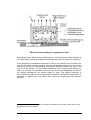
Gefriertrocknungsanlagen
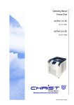
OPERATING MANUAL
Freeze Dryer
ALPHA 1-4 LD-2
(Best.-Nr. 101041 / 101141 / 101241)
ALPHA 2-4 LD-2
(Best.-Nr. 101042 / 101142 / 101242)
MARTIN CHRIST
Gefriertrocknungsanlagen GmbH
Operating Manual ALPHA 1-4 LD-2 and ALPHA 2-4 LD 2
Order Number:
Serial Number:
In case of inquiries or repair please state the above numbers.
For service please contact:
MARTIN CHRIST Gefriertrocknungsanlagen GmbH
An der unteren Sö se 50, D-37520 Osterode
Tel. (05522) 5007-25, Telefax (05522) 5007-12
Operating Manual Freeze Dryer ALPHA 1-4 LD-2 / 2-4 LD-2, Version 0203, Page 2
Preface
Dear customer,
Congratulations on purchasing a CHRIST freeze dryer.
The freeze dryer is equipped with user-friendly options which make the operation
easier for you.
The newly designed ALPHA 1-4 LD-2 / ALPHA 2-4 LD-2 is a universally usable
CHRIST freeze dryer for laboratories, R&D departments and scientific institutes. The
well proven range of accessories allows application oriented configuration of the
equipment especially for routine use. A practical and universally usable range of
accessories is available for almost all applications for drying in round bottom flasks,
dishes, ampoules and injection vials.
A special advantage is the user-friendly control system LD (Lyo-display), the functions
of which are explained on the control panel:
- LC display showing the most important process data (temperature of ice
condenser, vacuum)
- Conversion of temperature and vacuum in accordance with the vapour pressure
curve above ice
- RS-232 communications interface (PC) is available as an option.
Especially worth mentioning is the possible retrofitting of a vacuum measuring sensor
(type TPR 265) which only has to be plugged in at the back of the unit. This freeze
dryer offers a wide range of functions for a variety of practical applications.
We thank you for your confidence and wish you a successful application of the freeze
dryer.
MARTIN CHRIST Gefriertrocknungsanlagen GmbH
An der unteren Sö se 50 - D-37520 Osterode
Tel. +49 (0) 5522/5007-0, Telefax +49 (0) 5522/5007-12
Internet: www.martinchrist.de, e-mail: [email protected]
Operating Manual Freeze Dryer ALPHA 1-4 LD-2 / 2-4 LD-2, Version 0203, Page 3
Contents:
1
2
^
Page
General Information
1.1
Introduction
7
1.2
Application
7
1.3
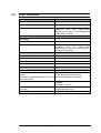
Technical specifications of freeze dryer ALPHA 1-4 LD-2 /
ALPHA 2-4 LD-2
8
1.4
Standards and regulations
10
1.5
Safety instructions
10
1.6
Prohibited freeze drying processes
11
Installation and Commissioning of the Unit
2.1
Site of installation
13
2.2
Mains electricity
13
2.3
Fuses on site
13
2.4
Checking the Earth connection
13
2.5
Defrosting water
14
2.6
Vacuum pump exhaust
14
2.7
Initial start-up
15
2.7.1
Connection of vacuum pump and installation of accessory
components
15
2.7.2
Functional components and control elements
21
2.7.3
Preparation for evacuation
22
2.7.4
Evacuation
22
2.8
Error messages
22
2.9
Error resolution
23
Operating Manual Freeze Dryer ALPHA 1-4 LD-2 / 2-4 LD-2, Version 0203, Page 4
3
4
5
6
Control System LD-2
24
3.1
Mains switch
25
3.2
"°C mbar" button
25
3.3
"≙ " Button
25
3.4
Connection of the vacuum measuring sensor TPR 265
26
General Information on Freeze Drying
27
4.1
Freezing
29
4.2
Main drying
30
4.3
Final drying
34
4.4
End of drying and venting
34
4.5
Defrosting
34
Description of the Freeze Drying Processes
5.1
Freezing separately and drying on shelves
35
5.2
Drying with sealing device
35
5.3
Freezing separately and drying in round bottom flasks
36
5.4
Freezing separately and drying in ampoules using a manifold
36
Maintenance
6.1
Vacuum pump
38
6.2
Exhaust filter
38
6.3
Ice condenser chamber
38
6.4
Rubber valves
38
6.5
Condenser for cooling liquid
39
6.6
Adjustment of the vacuum measuring sensor TPR 265
39
6.7
Cleaning
40
Operating Manual Freeze Dryer ALPHA 1-4 LD-2 / 2-4 LD-2, Version 0203, Page 5
7
8
6.7.1
Cleaning of the freeze dryer
40
6.7.2
Cleaning of accessories
40
6.7.3
Maintenance of the condensate drain valve
41
6.7.4
Disinfection of chamber and accessories
41
6.7.5
Operator checks
41
Instructions for Error Correction
7.1
Power failure
42
7.2
Insufficient vacuum
42
7.3
Unit does not function
43
7.4
Insufficient ice condenser temperature
44
Appendix
Declaration of conformity for ALPHA 1-4 LD-2 / 2-4 LD-2
… … … … … … … … … … … … … … … … … … … … … … … … … … … … … … … … … …
Explanation to the panels ALPHA 1-4 LD / 2-4 LD
Explanation to the panels ALPHA 1-4 LD-2 / 2-4 LD-2
… … … … … … … … … … … … … … … … … … … … … … … … … … … … … … … … … …
Operating manual of the vacuum pump (only in case of delivery)
Operating manual of the exhaust filter (only in case of delivery)
… … … … … … … … … … … … … … … … … … … … … … … … … … … … … … … … … …
… … … .Separate leaflat “
The freeze dryer of the ALPHA-series”
Accessories leaflat “
The accessory for freeze drying”
General leaflat “
The program of the freeze dryers”
… … … … … … … … … … … … … … … … … … … … … … … … … … … … … … … … … …
Chemical properties of PLEXIGLAS
(acrylic glass, material of drying chamber)
Disinfectant spray INCIDUR
Return Declaration
Declaration of Contamination
Operating Manual Freeze Dryer ALPHA 1-4 LD-2 / 2-4 LD-2, Version 0203, Page 6
1
General Information
1.1
Introduction
What is freeze drying?
Freeze drying means: Extraction of water from frozen material. The drying process
takes place by avoiding the liquid state through sublimation, i. e. direct conversion from
ice to vapour. This happens under vacuum, when the temperature in the product is
less than -10°C.
The aim of freeze drying is to obtain an easily water soluble product which will have
the same characteristics as the original product after addition of water.
As the drying process takes place in frozen state at very low temperatures it is possible
to dry e. g. albumen which will remain water soluble. Also most of the other chemical
compounds will be qualitatively and quantitatively unchanged.
Freeze drying (lyophilisation) is also the most gentle process for preserving the
biological properties of sensitive tissue and tissue components.
Through freeze drying the product, mainly of biological origin - such as tissues, tissue
extracts, bacteria, vaccines and sera - is transformed into a dry product. During this
process enzymatic, bacterial and chemical changes are largely avoided.
1.2
Applications
The freeze dryer ALPHA 1-4 LD-2 / ALPHA 2-4 LD-2 is a high-performance, universal
laboratory and pre-production unit for freeze drying of solid or liquid products in
ampoules, bottles, glass flasks, wide-neck filter bottles or dishes. All operations
necessary for freeze drying are possible inside the unit:
− Freezing
− Freeze drying
− Final drying
The freeze dryer ALPHA 1-4 LD-2 / ALPHA 2-4 LD-2 is suitable for drying of e. g.
bacteria and virus cultures, blood plasma, serum fractions, antibodies, sera, vaccines
and pharmaceutical products such as chloramphenicol, streptomycin, vitamins,
ferments as well as plant extracts for biochemical tests.
Operating Manual Freeze Dryer ALPHA 1-4 LD-2 / 2-4 LD-2, Version 0203, Page 7
1.3
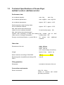
Technical Specifications of Freeze Dryer
ALPHA 1-4 LD-2 / ALPHA 2-4 LD-2
Performance data:
Ice condenser capacity:
max. 4 kg
max. 4 kg
Ice condenser performance:
max. 4 kg/24 h max. 4 kg/24 h
Ice condenser temperature:
Approx. -54°C approx. – 84°C
Shelf temperature when freezing inside
the ice condenser chamber:
Approx. -25°C approx. – 50°C
Max. shelf surface area when drying
outside the ice condenser chamber:
5x shelf surface areas
360
Max. shelf surface area when drying in
injection vials (according to DIN) with sealing Only outside, with
under vacuum or nitrogen atmosphere:
surface areas 250
4x
Drying in round bottom flasks, e. g. each 300 ml:
additional
24
pieces
chamber
with
shelf
Other data:
Dimensions of the unit:
width: 390 mm
height: 415 mm
depth: 540 mm
(incl. vacuum flange connection)
Weight:
approx. 42 kg
Noise emissions according to DIN 45635
dB (A)
Electromagnetic compatibility according to EN
55011:
class B
approx. kg
dB (A)
Filling quantities:
Refrigerant:
see label on the back of the unit
Connection requirements:
Electric connection:
230 V, 50 – 60 Hz
(others on request) and central
grounding connection
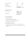
Operating Manual Freeze Dryer ALPHA 1-4 LD-2 / 2-4 LD-2, Version 0203, Page 8
Max. power consumption:
0,92 kVA
1,84 kVA
Max. current:
4,0 A
8,0 A
Safety precaution
6,3 AT
10 AT
Max. ambient temperature
climate category SN
+10°C to +32°C
(higher temperatures on request)
Equipment connections:
Vacuum connection:
small flange connection
DN 25 KF
(ISO 28403, DIN 2861)
Condensate drain:
hose nozzle DN 10 with
0.5 m silicon hose
(D=8 x s = 2mm)
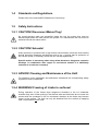
Scope of supply includes:
1 tube high-vacuum grease
1 litre vacuum pump oil (if pump is supplied)
1 operating manual and detailed technical documentation
0.5 m condensate drain hose (silicon 9 x 12 mm)
Scope of supply does not include:
− Commissioning of the unit will be carried out on request and charged at cost.
− Installation of the exhaust pipe of the vacuum pump (not necessary when using an
exhaust filter).
Operating Manual Freeze Dryer ALPHA 1-4 LD-2 / 2-4 LD-2, Version 0203, Page 9
1.4
Standards and Regulations
Please refer to the enclosed EU-Statement of Conformity.
1.5
Safety Instructions
1.5.1 CAUTION! Disconnect Mains Plug!
As current-carrying parts are accessible inside the unit the mains plug must be
disconnected before the side panels are opened. For maintenance the unit must be
switched off with the mains switch.
1.5.2 CAUTION! Solvents!
Acidic products or products with a high solvent concentration cannot be dried without
special protective measures and devices such as e.g. a cooling trap for protection of
the vacuum pump (if necessary check with our service department).
Special caution is necessary when using azides because a dangerous explosive
develops in combination with copper or non-ferrous metals! It is absolutely
essential to consult our company!
1.5.3 ADVICE! Cleaning and Maintenance of the Unit!
For infectious, toxic, pathogenic and radioactive substances the corresponding safety
regulations must be observed.
1.5.4 WARNING! Freezing of Limbs to surfaces!
During operation of the freeze dryer dangerous situations in the ice condenser
chamber may arise. When putting in the shelves take care that limbs do not come into
contact with the condenser in the ice condenser chamber as the limbs may become
frozen to the surface. The limb can only be detached from the surface by applying
heat. Liquid should not be used.
Operating Manual Freeze Dryer ALPHA 1-4 LD-2 / 2-4 LD-2, Version 0203, Page 10
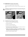
1.5.5 IMPORTANT! Transport instructions!
Please keep the packaging for possible subsequent dispatch.
The freeze dryer should be carried by two persons by holding it underneath on both
sides.
WARNING! When transporting or putting down the unit do not hold the plastic control
panel. Please note: When putting the unit down on a surface there is a danger of
squeezing hands or fingers.
RIGHT
1.6
WRONG
Prohibited Freeze Drying Processes
1. Operation of freeze dryer when not installed correctly.
2. Operation without panels.
3. Operation by non-authorised personnel.
4. Operation with shelves not installed properly.
5. Operation with very corrosive substances which can cause damage to material and
affect mechanical strength of chamber and shelves.
6. Operation with accessories not allowed by the manufacturer, except for
commercial freeze drying vessels made of glass or plastic. The user is explicitly
warned not to use poor quality goods. Breaking glass or bursting vessels can
cause dangerous situations during freeze drying.
7. Operation in locations with danger of explosion.
Operating Manual Freeze Dryer ALPHA 1-4 LD-2 / 2-4 LD-2, Version 0203, Page 11
8. During operation the freeze dryer must not be knocked or moved. Leaning against
or resting on the freeze dryer is not allowed.
9. Do not place potentially dangerous material, e. g. glass vessels containing liquids,
near the freeze dryer.
10. Products which could react to the supply of high energy during the freeze drying
process must not be dried.
11. Do not freeze dry explosive or highly inflammable substances.
12. Substances which could damage the material of the shelves or the chamber in any
way must not be dried or may only be dried when special safety measures are
observed. Infectious, toxic, pathogenic and radioactive substances must only be
dried in suitable vessels.
Operating Manual Freeze Dryer ALPHA 1-4 LD-2 / 2-4 LD-2, Version 0203, Page 12
2
Installation and Commissioning of the Unit
2.1
Site of Installation
WARNING! Papers, cloths or similar items must not be put behind the unit as the air
circulation of the heat exchanger will not work any more.
The freeze dryer should be positioned horizontally. The ambient temperature should be
within approx. +15°C and +25°C.
The refrigerator of the freeze dryer is air-cooled. Sufficient air circulation must be
ensured. A distance of at least 30 cm to the wall should be kept. The unit should not be
positioned near radiators or heat sources and direct insolation must be avoided.
In the event of insufficient air circulation or a too high ambient temperature pressure
and temperature in the refrigerating system will increase.
The following connections are necessary at the site:
2.2
Mains Electricity
The voltage given on the name-plate must correspond to the local supply voltage.
CHRIST freeze dryers are units of safety class I and include a three-conductor
connection cable and a shockproof plug.
2.3
Fuses on Site
The freeze dryer must be protected typically with a 16 A fuse.
2.4
Checking the Earth Connection
For checking the earth connection there is a screw for equalising the ground potential
on the back panel of the freeze dryer. The check can be carried out by means of an
appropriate measuring device.
Operating Manual Freeze Dryer ALPHA 1-4 LD-2 / 2-4 LD-2, Version 0203, Page 13
2.5
Defrosting Water
The defrosting water is drained via the condensate drain valve on the left side of the
unit. To drain the water place the hose supplied with the unit onto the nozzle. The
defrosting water is collected in a vessel.
The defrosting water can also be drained directly via this hose. The defrosting water
must be able to drain freely. To achieve this the hose must have a steady downward
slope. It must be ensured that water does not collect in any part of the hose. The end
of the hose always has to be above the level of the liquid in the vessel for the
discharged defrosting water. Otherwise there is the risk of water and dirt residues
being sucked into the condenser chamber if there is a vacuum when opening the
condensate drain valve.
2.6
Vacuum Pump Exhaust
During the main drying phase the vacuum pump must be operated with open gas
ballast valve. The oil mist which is produced must be removed.
A ½ " hose is connected to the exhaust flange of the vacuum pump RZ-2 or RC-5 and a
¾ " hose is connected to the exhaust flange of the vacuum pump DUO 005 or DUO
010. The hose either leads into the open air or into a vent.
During installation of the pipe care must be taken that condensate cannot flow back
into the pump. With upward leading pipes it is safest to use a separator (Woulfe's
bottle or wash bottle) in the pipe.
If draining of the oil mist should not possible we recommend that an exhaust filter (oil
mist separator) is fitted. This filter prevents air pollution by oil mist which is emitted by
the vacuum pump in smaller or larger quantities depending on the working pressure.
The filter is fastened to the exhaust flange of the vacuum pump.
The filter is equipped with a pressure control valve which indicates the saturation of the
filter. Cleaning or replacing of the filter insert must be carried out at the latest when the
pressure control valve is activated. The collected oil is visible in the inspection glass
and is drained via the discharging screw.
(Please refer to separate operating manual of the vacuum pump!)
Operating Manual Freeze Dryer ALPHA 1-4 LD-2 / 2-4 LD-2, Version 0203, Page 14
2.7
Initial start-up
CAUTION! Ensure that the freeze dryer is correctly mounted and installed before
initial start-up (see point 2.1 Site and following points).
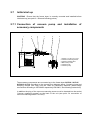
2.7.1 Connection of vacuum pump and installation of
accessory components
1
2
3
3
4
5
6
1 ALPHA 1-4 LD-2 / 2-4 LD-2
2 Vacuum measuring sensor
3 Vacuum release valve
4 Manual stop valve
5 Vacuum hose
6 Vacuum pump
The accessory components are connected up to the freeze dryer ALPHA 1-4 LD-2 /
ALPHA 2-4 LD-2 according to the process flow diagram above. Centering rings and
clamping flanges with wing nuts are used as connecting elements (small flange
connections according to ISO 28403 respectively DIN 2861, see following instructions)
In addition the plug of the vacuum measuring sensor must be inserted into the socket
“
Vacuum measuring sensor” on the back of the unit (see point 3.4 connection of
vacuum measuring sensor TPR 265).
Operating Manual Freeze Dryer ALPHA 1-4 LD-2 / 2-4 LD-2, Version 0203, Page 15
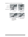
Instructions on connecting centering rings and clamping flanges
Vacuum hose
Centering ring
Clamping flange
Vacuum release valve
(separate accessory)
A
C
Lay-out assembly of
vacuum connections.
Connect second flange
(the centering ring must
be positioned correctly!)
and place clamping flange
over the connection and
press together.
B
Place centering ring on
one side of small flange
connection
(e. g. vacuum hose).
D
Tighten the screw of the
clamping flange by hand.
Operating Manual Freeze Dryer ALPHA 1-4 LD-2 / 2-4 LD-2, Version 0203, Page 16
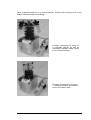
Other ordered accessories (e.g. drying chamber, shelves and connections for round
bottom flasks) are added accordingly.
Example: Accessory for drying on
5 unheated shelves as well as
individually sealable rubber valves
for round bottom flasks.
Example: Accessory for drying on
2 unheated shelves with sealing
device for injection vials.
Operating Manual Freeze Dryer ALPHA 1-4 LD-2 / 2-4 LD-2, Version 0203, Page 17
Schematic diagram of accessories
Drying chamber 300
with 12 connections
Ground-in stopper
Rubber valve
Drying vessel,
e.g. round bottom
flasks
Ampoule manifold
Additional chamber 300
with 12 connections
Drying vessel, e.g.
ampoule
3 or 5 shelves
265, unheated
Drying vessel, e.g. injection vial
Product dish
Drying chamber
Stoppering device with 1 shelf,
250, unheated, max. 4
shelves can be used
300
Drying vessel, e.g. injection vial
Drip tray
Base plate
ALPHA 1-4 LD-2
ALPHA 2-4 LD-2
Operating Manual Freeze Dryer ALPHA 1-4 LD-2 / 2-4 LD-2, Version 0203, Page 18
Rubber valve
Manifold, different versions, max.
24 rubber valves
Drying vessel, e.g..
wide neck filter
Drying chamber, e.g.
round bottom flaks
Drying vessel, e.g. injection vial
Lid
300
ALPHA 1-4 LD-2
ALPHA 2-4 LD-2
Operating Manual Freeze Dryer ALPHA 1-4 LD-2 / 2-4 LD-2, Version 0203, Page 19
Drying chamber
Rubber valve
457
Connection pipe for rubber valve,
for enlarging the drying chamber
max. 18 pieces
Ampoule
manifold
Drying vessel, e.g.
Ampoule
Drying vessel, e.g.
round bottom flasks
Drying vessel, e.g. injection
vial
5 shelves
unheated
360,
Product dish
Connection flange
ALPHA 1-4 LD-2
ALPHA 2-4 LD-2
Operating Manual Freeze Dryer ALPHA 1-4 LD-2 / 2-4 LD-2, Version 0203, Page 20
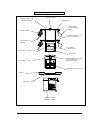
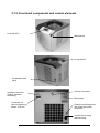
2.7.2 Functional components and control elements
Controler LD-2
Mains switch
Ice condenser
Condensate drain
valve
Interface connection
(Option, seperate
accessory)
Vacuum connection
Name-plate
Connection for
vacuum measuring
sensor TPR 265
Potential equalizing screw
and central grounding
connection
Connection for mains
cable and fuse
Operating Manual Freeze Dryer ALPHA 1-4 LD-2 / 2-4 LD-2, Version 0203, Page 21
2.7.3 Preparing for Evacuation
The drying chamber made from acrylic glass with ground-in stoppers is placed on the
ice condenser chamber.
The defrosting water valve at the left side of the unit and any rubber valves on the
drying chamber are closed.
The vacuum pump is connected to the unit and to the mains.
2.7.4 Evacuation
The drying chamber is evacuated by switching on the vacuum pump.
After switching on the pump it must not be possible to lift the acrylic chamber or lid
anymore.
2.8
Error messages
A possible error is showed in form of “
ER : XX” (Error) in the lower part of the LCDisplay. “
XX”is marking the error code. In case of a fault, the display changes in one
second intervals between error code and value display until the mains voltage is
switched on and of.
All errors can be removed through the following measures:
-
Switching on and of the mains voltage (mains switch; Power – On-Reset).
Over the communication interface by using the command “
reseterr”
Error number
Meaning, possible cause
ER10
Compressor 1 overpressure
Compressor turns off (until overpressure is
reducted)
ER 11
Compressor 2 overpressure
Compressor turns off (until overpressure is
reducted)
Operating Manual Freeze Dryer ALPHA 1-4 LD-2 / 2-4 LD-2, Version 0203, Page 22
2.9
Error resolution
Error
Measure
Start of the instrument is not possible
1. Mains failure
Mains plug connected?
Check the fuse of the freeze dryer (Mains
connection cord, fuse insert cord)
respectively the fuse of the building and
exchange if necessary
No display
Mains plug connected?
Check the fuse of the freeze dryer (Mains
connection cord, fuse insert cord)
respectively the fuse of the building and
exchange if necessary
Refrigeration system does not work
No vacuum
1. Position of the centering rings is not
correct
(Connection hose between vacuum pump
and cooling trap)
2. Lid seal not tight
Open small flange connection,
insert Centering rings centrically,
use vacuum grease if necessary
Cleaning; call service if lid seal is
damaged
(Contact on page. 2)
3. Condensate drain valve defect (does Cleaning; exchange O-rings of the
not close)
condensate drain valve
Operating Manual Freeze Dryer ALPHA 1-4 LD-2 / 2-4 LD-2, Version 0203, Page 23
3
Control System LD-2
A particular advantage of the user friendly LD control system (Lyo-display) is that all
functions are explained on the control panel.
- LC display showing the most important process data (temperature of ice
condenser, vacuum)
- Conversion of temperature and vacuum in accordance with the vapour pressure
curve above ice
- RS-232 communications interface (PC) is available as an option.
Operating Manual Freeze Dryer ALPHA 1-4 LD-2 / 2-4 LD-2, Version 0203, Page 24
3.1
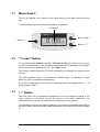
Mains Switch
The unit is switched on by means of the mains switch on the upper right side of the
unit.
The LED-display lights up and the refrigerator is in operation.
LC-Display
Button "mbar"
Button "≙ "
Button "°C"
3.2
"° C mbar" Button
On the freeze dryer ALPHA 1-4 LD-2 / ALPHA 2-4 LD-2 the vacuum in the drying
chamber or alternatively the ice condenser temperature can be displayed. The changeover is carried out by pressing the "° C " or “ mbar” button.
The vacuum measuring sensor TPR 265 (accessory) is necessary for measuring the
vacuum.
The upper pressure range - not important for freeze drying - is displayed in rough
steps only ("A" corresponds to atmosphere).
If the unit is not equipped with a vacuum measuring sensor the display shows "----" at
switch position "mbar".
3.3
"≙ " Button
With this button the ice condenser temperature can be converted according to the
vapour pressure curve above ice into the vacuum in the drying chamber or the
measured vacuum can be converted into the temperature of the samples.
The possibility to convert the vapour pressure curve serves as orientation and helps to
show the relation between pressure and temperature during freeze drying (see chapter
4).
Operating Manual Freeze Dryer ALPHA 1-4 LD-2 / 2-4 LD-2, Version 0203, Page 25
3.4
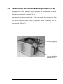
Connection of the Vacuum Measuring Sensor TPR 265
Units without a vacuum measuring sensor can easily be retrofitted with the sensor
TPR 265 for measuring the vacuum. To do this the plug of the measuring sensor is
inserted into the socket on the back of the unit.
The measuring sensor is supplied with a T-piece with small flange connections. With
this T-piece the sensor is connected to the connection at the rear panel of the unit.
The vacuum measuring sensor must be adjusted If another value other than “
A”
(atmosphere) is displayed after switching on the unit (see point 6.6 “
Adjustment of
vacuum sensor TPR 265”).
Vacuum measuring
sensor TPR 265
Connecting plug for
vacuum measuring
sensor TPR 265
Operating Manual Freeze Dryer ALPHA 1-4 LD-2 / 2-4 LD-2, Version 0203, Page 26
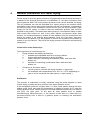
4
General Information on Freeze Drying
Freeze drying is the most gentle process for drying biological and chemical products. It
is based on the physical phenomenon of sublimation i.e. the direct conversion from
solid to gaseous state. The frozen product is placed in the vacuum chamber for drying.
The ice condenser can also be described as a vapour pump as the moisture which
evaporates under vacuum during drying freezes onto the ice condenser. Consequently
the vacuum pump is only intended to remove the air from the drying chamber (=gas
pump) but not the vapour. In order to start the sublimation process, heat must be
supplied to the product. This takes place during drying in round bottom flasks or wideneck closed filter bottles etc. due to the much warmer environment (direct heat
contact), on unheated shelves by means of heat radiation from the environment and
directly by means of the shelves when heatable. Once the “
free water” has been
removed from the product, it is also possible to remove the crystalline bound water by
means of very low vacuum. This part of the drying process is referred to as final drying
(desorption).
Construction of the freeze dryer
The components of a freeze dryer are :
•
Drying chamber and heating accessories
a
heatable and unheatable shelves for drying in dishes
b
shelves with sealing device for drying in bottles
c
rubber valves for connecting round bottom flasks, wide-neck filter
bottles, etc.
d
manifold for connecting round bottom flask, wide-neck filter
bottles, etc.
•
Pumps for air and water vapour
a
vacuum pump to evacuate the drying chamber (= gas pump)
b
ice condenser with temperatures from -50°C to -110°C (depending on
type of unit) to condense the water vapour (= vapour pump ).
Sublimation
The principle of sublimation is briefly explained using the phase diagram of water
(freeze drying of mainly aqueous solutions, see vapour pressure curve).
If the atmospheric pressure is higher than 6.11 mbar, water passes through all three
phases (solid, liquid, gas) when the temperature is lowered or raised. At 6.1 mbar the
melting pressure curve, vapour pressure curve and sublimation pressure curve meet in
one point, the triple point. At this point all three phases occur in parallel
(simultaneously). Below this point, i.e. the vacuum is lower than 6.11 mbar, the ice is
converted directly from a solid to a gaseous phase on reaching the sublimation
pressure curve.
Operating Manual Freeze Dryer ALPHA 1-4 LD-2 / 2-4 LD-2, Version 0203, Page 27
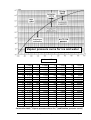
Vapour pressure curve for ice and water
1mbar = 10²Pa
0
-1
-2
-3
-4
-5
-6
-7
-8
-9
-10
-11
-12
-13
-14
-15
-16
-17
-18
-19
= mbar
6,110
5,620
5,170
4,760
4,370
4,020
3,690
3,380
3,010
2,840
2,560
2,380
2,170
1,980
1,810
1,650
1,510
1,370
1,250
1,140
°C
-20
-21
-22
-23
-24
-25
-26
-27
-28
-29
-30
-31
-32
-33
-34
-35
-36
-37
-38
-39
= mbar
1,030
0,940
0,850
0,770
0,700
0,630
0,570
0,520
0,470
0,420
0,370
0,340
0,310
0,280
0,250
0,220
0,200
0,180
0,160
0,140
°C
-40
-41
-42
-43
-44
-45
-46
-47
-48
-49
-50
-51
-52
-53
-54
-55
-56
-57
-58
-59
= mbar
0,120
0,110
0,100
0,090
0,080
0,070
0,060
0,055
0,050
0,045
0,040
0,035
0,030
0,025
0,024
0,021
0,018
0,016
0,014
0,012
°C
-60
-61
-62
-63
-64
-65
-66
-67
-68
-69
-70
-71
-72
-73
-74
-75
-76
-77
-78
-79
= mbar
0,011
0,009
0,008
0,007
0,006
0,0054
0,0047
0,0047
0,0035
0,0030
0,0026
0,0023
0,0019
0,0017
0,0014
0,0012
0,0010
Conversion table " Vapour pressure above ice " (sublimation pressure curve)
Operating Manual Freeze Dryer ALPHA 1-4 LD-2 / 2-4 LD-2, Version 0203, Page 28
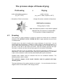
The process steps of freeze drying
Prefreezing
+
Drying
under atmosphere pressure
(e.g. at - 25°C)
under vacuum
(e.g. at 0.1 mbar, equal to -42°C)
= formation of the ice structure
= keeps the water contents in the phase
Additionally necessary:
Energy input (= heat)
but: the material remains in the solid/ice phase!
(physical law: the vacuum is responsible
for the product-/steam temperature)
4.1
Freezing
The freezing of small quantities of product is carried out inside the ice condenser
chamber of the ALPHA 1-4 LD-2 / ALPHA 2-4 LD-2. Larger quantities are pre-frozen
in a deep-freeze.
If liquids are to be dried in bottles with a layer thickness of more than 1 cm we
recommend that pre-freezing is carried out with a shell or spin-freezing-device in a
cooling bath (see previous picture). Due to the centrifugal force the liquid to be frozen
will rise on the wall of the bottle and freeze. With this freezing process the layer
thickness is reduced and thus the total drying period is shortened considerably.
Freezing inside the unit is not necessary if the product is pre-frozen or stored in e. g. a
deep-freeze. In this case, especially when freeze drying small quantities, it is advisable
to pre-cool the shelves in order to avoid partial thawing during the evacuation.
Possible water residue must be removed from the ice condenser chamber. The
defrosting water valve is closed.
The ground-in stopper of the acrylic chamber must be greased with highvacuum grease!
The layer thickness of the product should not exceed 1 - 2 cm as otherwise this has a
negative effect on the duration of the drying process.
Operating Manual Freeze Dryer ALPHA 1-4 LD-2 / 2-4 LD-2, Version 0203, Page 29
4.2
Main Drying
The vacuum pump is switched on.
Please note:
Defrosting during the drying process is possible (visible foaming) when drying products
containing e. g. solvents or high salt concentrations. In this case it is necessary to
freeze the product as low as possible, e.g. in liquid nitrogen.
Warning:
Acidic products or products with a high solvent concentration cannot be dried without
special protective measures and devices e.g. a cooling trap for protection of the
vacuum pump (if necessary contact our company).
Special precautions are necessary when using azides because a dangerous
explosive develops in combination with copper or non-ferrous metals! It is
absolutely essential to consult our company!
As soon as sublimation of the water vapour from the frozen product begins, heat is
extracted and consequently the product continues to cool down.
The maximum rate of sublimation is reached at the start of the drying process.
Depending on the rate of sublimation the ice condenser temperature and thus the
pressure in the drying chamber respectively ice condenser chamber rises.
The duration of the main drying phase depends mainly on:
− the layer thickness of the product
− the solid content of the product
− the heat supplied to the product during the drying process
− the pressure inside the drying chamber during the drying process
With increasing pressure (not vacuum!) the rate of sublimation rises and the drying
period is shortened.
The water vapour generated during the main drying phase is not pumped off by the
vacuum pump but collected by the ice condenser.
The purpose of the vacuum pump is to lower the partial pressure of the noncondensable gases so that the water vapour can be transported from the product to
the ice condenser.
However, small quantities of water vapour are also pumped off by the vacuum pump.
Therefore, the vacuum pump is equipped with a gas ballast device.
Operating Manual Freeze Dryer ALPHA 1-4 LD-2 / 2-4 LD-2, Version 0203, Page 30
If the gas ballast valve is open the extracted condensable vapours will be emitted via
the exhaust pipe together with air.
For this reason the gas ballast valve must be open during the main drying
phase!
The gas ballast valve can only be closed for final drying.
During the main drying phase the moisture is removed by sublimation, during final
drying the bound moisture is removed by desorption.
This small quantity of water vapour generated during the final drying phase can be
pumped off even when the gas ballast valve is closed (for several hours).
In general, operation with closed gas ballast valve is not necessary. The vacuum pump
used reaches with open gas ballast valve a final pressure which corresponds to the
water vapour partial pressure that can be reached.
The residual moisture of the dried product depends mainly on:
− the temperature of the dried product during the final drying process
− the final vacuum reached during the final drying process
The end of the main drying phase is reached, when the product temperature is nearly
the same as the shelf temperature (temperature difference between shelf and product
approx. 3°C to 5°C ). If the crystalline bound water is to be removed from the product,
the final drying phase can be started.
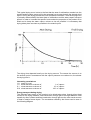
The following picture shows the drying process for a product containing approx. 10%
solid matter. During the first quarter of the main drying phase 50 % of the water
content is condensed. During the next quarter of the main drying phase 50 % of the
remaining water content is condensed. This continues until the drying curve
approaches the time axis asymptotically.
Operating Manual Freeze Dryer ALPHA 1-4 LD-2 / 2-4 LD-2, Version 0203, Page 31
This typical drying curve is due to the fact that the area of sublimation recedes into the
product and the water vapour still to be extracted has to pass through the already dried
layers. During the drying process the inner resistance increases. Thus the drying curve
is primarily determined by the latent heat of sublimation and the water vapour transport
speed. In order to increase the specific heat conduction properties of the product to be
dried and to keep the water vapour volume as low as possible it is necessary that
drying takes place as close as possible to the eutectic point.
The drying time depends heavily on the drying vacuum. The nearer the vacuum is to
the eutectic point in accordance with the vapour pressure curve above ice, the shorter
the drying time is.
Interesting correlations:
1.0 gram of ice at
1.0 mbar assumes a volume of
0.1 mbar assumes a volume of
0.01 mbar assumes a volume of
1 m³ vapour
10 m³ vapour
100 m³ vapour
Energy transport during drying
The required heat supply to the product to be dried takes place through direct heat
contact in the drying chamber, heat conduction through gas or through radiation. Heat
transfer by direct contact and heat conduction through gas are the most usual sources
of heat in today’s freeze dryers. The constraints caused by the former can be seen in
the following diagram.
Operating Manual Freeze Dryer ALPHA 1-4 LD-2 / 2-4 LD-2, Version 0203, Page 32
Effects of freeze drying of a product in a dish
Heat transfer takes place via the heated shelves1, via direct contact with the bottom of
the vessel and/or via the gas between the shelves and vessel by means of convection.
At the beginning of sublimation the transfer of heat is very effective from the wall of the
vessel to the frozen product. However, soon an area develops which is ice free, porous
and dried and has a corresponding temperature gradient between the wall of the
vessel and the product. The poor heat conductivity of the already dried product can
lead to an increase in temperature of the ice core. If the core temperature rises above
the melting temperature, the product begins to thaw. This applies especially to
inhomogeneous products and to great layer thicknesses. During this drying phase it is
important to regulate the heat supply and control the temperature and pressure
precisely.
1
In so far as there are heated shelves, otherwise via radiation on the walls of the vessel or the
exposed surface of the product
Operating Manual Freeze Dryer ALPHA 1-4 LD-2 / 2-4 LD-2, Version 0203, Page 33
4.3
Final Drying
The final pressure in the drying chamber depends on the ice condenser temperature
according to the vapour pressure curve above ice:
e. g.
1.030 mbar correspond to -20°C
0.370 mbar correspond to -30°C
0.120 mbar correspond to -40°C
0.040 mbar correspond to -50°C
0.011 mbar correspond to -60°C
The unit is in operating condition if the temperature of the ice condenser is lower than
-50°C and the pressure is lower than 0.120 mbar.
The final pressure measured by the vacuum sensor when there is no product in the
unit and its corresponding ice temperature value is mainly determined by the warmest
place of the ice on the ice condenser chamber. Moreover, this value is affected by
residues or parts of solvents in the product with a higher vapour pressure.
4.4
End of Drying and Venting
A rough indication of the end of drying is the vacuum and the ice condenser
temperature. The ice condenser is no longer loaded and reaches the final temperature
of approx. -50°C to -54°C. The pressure in the drying chamber decreases according to
the ice condenser temperature.
The vacuum pump is switched off and the drying chamber is vented by a rubber valve
or the defrosting water valve. A vacuum release valve for venting with nitrogen,
another inert gas or air is available as accessory.
Then the unit is switched off and the product is removed.
4.5
Defrosting
Defrosting of the ice condenser is carried out at room temperature or with warm water.
At a maximum the ice condenser chamber may be half filled with water.
During filling it is important that no water gets into the pipe connection for the vacuum
pump and vacuum measuring sensor!
The defrosting water is drained through the defrosting water valve at the left side of the
unit. To do this, a hose is put onto the nozzle. The defrosting water is collected in a
vessel.
Operating Manual Freeze Dryer ALPHA 1-4 LD-2 / 2-4 LD-2, Version 0203, Page 34
5
Description of the Freeze Drying Processes
5.1
Freezing Separately and Drying on Shelves
Possible water residue is removed from the ice condenser chamber. The defrosting
water valve is opened and closed again so that the water residue can be drained. The
ice condenser chamber should be wiped If necessary.
For pre-cooling the ice condenser the ALPHA 1-4 LD-2 / ALPHA 2-4 LD-2 is switched
on.
The rack is put onto the bottom plate. For smaller samples it is advisable to pre-cool
the shelves in order to avoid a partial thawing during the evacuation process.
As soon as the shelves with the pre-frozen samples have been put in, the unit is
sealed with the drying chamber and the vacuum pump is switched on.
5.2
Drying with Sealing Device
With the sealing device injection bottles can be sealed with ribbed rubber stoppers on
one or two shelves under vacuum or inert gas. To do this the shelves are moved
against each other by a pressure plate using a spindle.
The height of the pressure plate must be adjusted according to the height of the
bottles. The screw for height adjustment is removed.
The threaded rod is screwed into the lower shelf until its slotted head is even with the
black balls of the guide rod.
Then the pressure plate is fastened with the adjustment screw in such a way that it will
rest on or slightly above the rubber stopper. When using two shelves the lower one as
well as the pressure plate are put directly or immediately above the rubber stoppers.
Instead of the stopper the vacuum-tight rotary leadthrough is put into the standard
ground socket of the acrylic chamber. Before inserting, the ground-in surface of the
leadthrough is greased with vacuum grease.
After completion of the drying process the lever of the rotary leadthrough is turned to
the right until a resistance is felt.
For the sealing of the bottles all shelves must be completely filled. For small quantities
at least three spacers must be evenly put on each shelf (according to the height of the
bottles with rubber stoppers).
The appropriate spacers are available on request.
Operating Manual Freeze Dryer ALPHA 1-4 LD-2 / 2-4 LD-2, Version 0203, Page 35
5.3
Freezing Separately and Drying of Flasks
Possible water residue is removed from the ice condenser chamber. The defrosting
water valve is opened and closed again so that the water residue can be drained. The
ice condenser chamber should be wiped if necessary.
For pre-cooling the ice condenser the ALPHA 1-4 LD-2 / ALPHA 2-4 LD-2 is switched
on.
For drying outside of the ice condenser chamber different manifolds are available (see
accessory catalogue). The drying chamber with 8 connections is mounted on the
sealing ring on the bottom plate of the ALPHA 1-4 LD-2 / ALPHA 2-4 LD-2. Manifolds
with standard ground joints NS 45/40 are connected via the ground-in socket of the
acrylic chamber.
In order to ensure a vacuum-tight connection and to simplify removal of the manifolds
the ground-in surface must be slightly greased with vacuum grease before use. The
manifold is then put on and turned by 360° for even distribution of the grease.
Before the vacuum pump is switched on it is necessary to check that all valves are
closed.
CAUTION! The frozen samples cannot be connected to the valves until a pressure of
less than 1.030 mbar is reached.
Liquids are frozen in flasks according to the shell-freezing principle, manually or with a
turning device. Due to this freezing process the layer thickness is reduced and the
drying period is considerably shortened.
The rubber valves allow a continuous connection and removal of flasks during the
drying process. Each rubber valve is equipped with a separation and venting device.
If the rubber valves are stiff they must be dismantled, cleaned, slightly greased with
vacuum grease and reassembled.
Using a distributor a maximum of 15 ampoules can be simultaneously frozen in the
cooling bath and connected to the manifold.
5.4
Freezing Separately and Drying of Ampoules
Using a Manifold
The manifold is equipped with dummy plugs for connection of max. 48 ampoules so
that it can be pre-evacuated.
The first hose is clamped in the middle with the supplied hose clamp and the blind plug
is removed. The vacuum is preserved in the system.
The liquid in the ampoule is either frozen in a deep-freeze or under rotation in a cooling
bath.
Operating Manual Freeze Dryer ALPHA 1-4 LD-2 / 2-4 LD-2, Version 0203, Page 36
If shock-freezing is required we recommend that freezing is carried out in liquid
nitrogen or in a cooling bath.
The ampoule is then connected to the hose and the hose clamp is removed. Thus the
partial pressure in the ampoule is suddenly decreased and a partial thawing during the
evacuation process is avoided.
With this procedure one ampoule after the other is connected.
Sealing of the ampoule is carried out in the same way. The hose of the ampoule to be
sealed is clamped and the ampoule is sealed under vacuum using the blow lamp.
If the ampoule breaks during sealing the vacuum in the drying chamber is not affected
due to the clamping with the hose clip.
The remaining glass from the ampoule is removed and the hose is closed with a
dummy plug.
In this way one ampoule after the other can be sealed or new ampoules can be
connected.
Operating Manual Freeze Dryer ALPHA 1-4 LD-2 / 2-4 LD-2, Version 0203, Page 37
6
Maintenance
6.1
Vacuum Pump
For maintenance of the vacuum pump please refer to the enclosed instructions.
Additionally, we would like to emphasise the following points:
The oil level of the vacuum pump must be regularly checked using the inspection glass
(in case of continuous operation at least once a week). Top up oil to the required level
via the oil inlet. Due to the continuous operation with gas ballast oil consumption
cannot be avoided. For topping-up see the instructions for the pump.
The first oil change must be carried out after approx. 100 operating hours. Subsequent
oil change intervals depend on the operating conditions. In general, an oil change is
necessary after approx. 500 to 1000 operating hours.
The oil change should always be carried out with warm pump.
6.2
Exhaust Filter
If the unit is equipped with an exhaust filter (necessary if the exhaust gases cannot be
extracted into the open air or into a vent) take care that the condensate in the filter
does not rise too high. The condensate is drained using a waste oil drain screw at the
filter.
(Please refer to separate operating manual!)
6.3
Ice Condenser Chamber
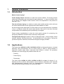
Before each start-up ensure that all water residue has been removed from the ice
condenser chamber. If necessary, wipe the ice condenser chamber.
We recommend that the defrosting water valve is opened and closed before each
drying process.
6.4
Rubber Valves
Special attention must be paid to the rubber valves. If the valves are stiff, they must be
dismantled, cleaned, slightly greased with vacuum grease and reassembled.
Operating Manual Freeze Dryer ALPHA 1-4 LD-2 / 2-4 LD-2, Version 0203, Page 38
6.5
Condenser of Cooling Liquid
A laminated condenser for cooling liquid is used to cool the refrigerant compressed by
the refrigerator. The condenser for cooling liquid is placed at the bottom of the unit. In
intervals of a few months it must be checked for dust or dirt residues and cleaned if
necessary. Cleaning of the heat exchanger can be carried out best by brushing, by
using a vacuum cleaner from the outside or by using compressed air from inside the
unit.
Excessive dirt on the condenser for cooling liquid leads to a decrease in performance
and can lead to a failure of the unit!
Please note: The unit must not be turned upside down!
6.6
Adjustment of the Vacuum Measuring Sensor TPR 265
Adjustment of the vacuum measuring sensor should be carried out at least once a year
if the unit is used continuously. Otherwise the operating point of the measuring sensor
can change, e. g. "800 mbar" is indicated instead of "A" (atmosphere).
For adjustment of the sensor, two values must be set:
"A"
"HV"
= Atmosphere
= High-vacuum
The high-vacuum range of the sensor is more stable so that a adjustment is in most
cases only necessary for atmosphere.
"A" Adjustment:
− Insert the plug of the sensor TPR 265 into the socket at the rear panel of
ALPHA 1-4 LD-2 / ALPHA 2-4 LD-2, switch on the unit and preselect the vacuum
display.
− Switch on the vacuum pump and let it warm up for approx. 15 minutes.
− Mount the TPR 265 on the vacuum connection piece of the vacuum pump.
− Switch on the vacuum pump and evacuate for approx. 3 minutes, then vent the unit
slowly.
− Wait for approx. 10 minutes. For the adjustment of the atmospheric value it is
important that the TPR 265 must be in exactly the same place as it will be used in
later!
− Press the conversion button "=" of ALPHA 1-4 LD-2 / ALPHA 2-4 LD-2 and set the
transition point in the display from "A-FF" to "A-or" (i. e. between "FF" and
"Overrange") using the potentiometer "ATM" of the TPR 265.
Operating Manual Freeze Dryer ALPHA 1-4 LD-2 / 2-4 LD-2, Version 0203, Page 39
"HV" Adjustment:
The high-vacuum adjustment must be carried out with a two-stage slide vane rotary
vacuum pump in good working order:
− Mount the TPR 265 on the vacuum pump and evacuate for approx. 10 minutes.
− Set the transition point in the vacuum display of ALPHA 1-4 LD-2 / ALPHA 2-4 LD2 between 0.0026 mbar and 0.0030 mbar using the potentiometer "HV" of the TPR
265.
Vent the unit slowly and carry out the adjustment process once again.
If problems arise during the adjustment process of the vacuum measuring sensor, the
vacuum sensor must be sent to Christ to be checked. The vacuum measuring sensor
has a limited life time. Defective sensors are exchanged.
6.7
Cleaning
6.7.1 Cleaning of the Freeze Dryer
Use soap water or other water-soluble, mild agents for cleaning of the freeze dryer.
Avoid corrosive and aggressive substances. Do not use alkaline solutions or solvents
or agents with abrasive particles. Remove product residues from the chamber using a
cloth. It is recommended that the lid to the freeze dryer is left open when the freeze
dryer is not in use so that moisture can evaporate. If there is the risk of toxic,
radioactive or pathogenic contamination, special safety measures must be
considered and adhered to.
6.7.2 Cleaning of Accessories
When looking after accessories special safety measures must be considered as these
are measures to ensure operational safety and reliability.
Chemical reactions as well as stress corrosion cracking (combination of changing
pressure and chemical reaction) can affect or destroy the structure of the metals and
plastic parts. Hardly detectable cracks on the surface expand and weaken the material
without visible signs. When visible damage of the surface, a crack, a mark or any other
change, as well as corrosion is detected, the part in question (shelf, vessel, drying
chamber etc.) must be replaced immediately for safety reasons.
Fans, lid seal, vessels, racks, acrylic chamber and shelves must be cleaned regularly
In order to avoid damage.
Operating Manual Freeze Dryer ALPHA 1-4 LD-2 / 2-4 LD-2, Version 0203, Page 40
Cleaning of accessories should be carried out away from the freeze dryer once a week
or preferably after every use. If there is the risk of toxic, radioactive or pathogenic
contamination, special safety measures must be considered and adhered to.
Aluminium accessories are particularly subject to corrosion. A neutral agent with a pHvalue between 6 and 8 should be used for such parts. Alkaline agents (pH > 8) must
be avoided. Thus life time is increased and corrosion is reduced considerably.
Careful maintenance through the user increases life time and avoids premature failure
of accessories. Damage caused by insufficient care does not constitute a warranty
claim.
6.7.3 Maintenance of the Condensate Drain Valve
Special attention must be paid to the condensate drain valve. If residues from previous
drying processes deposit on it, there is the risk of faulty operation of the freeze dryer.
Therefore, take care that no product or other residues will get into the pipe to the
condensate drain valve.
6.7.4 Disinfection of Chamber and Accessories
All usual disinfectants like e. g. INCIDUR, Melisiptol, Sagrotan, Buraton or Terralin
(available at laboratory retail suppliers) can be used.
NOTE! Check compatibility with lid; also see enclosure “
Chemical properties of
PLEXIGLAS (acrylic glass).
The freeze dryers and the accessories consist of different materials. A possible
incompatibility must be considered. For autoclaving the temperature stability of the
individual material must be checked. Please consult us if in doubt. If dangerous
materials are used, the freeze dryer and the accessories must be disinfected.
6.7.5 Checks by Operator
The operator has to ensure that the important parts of the freeze dryer relevant for
safety are not damaged.
This especially refers to:
1.
2.
3.
4.
Acrylic lid or acrylic chamber
Seals
Oil level of vacuum pump
Accessories, especially changes like corrosion, cracks, wear and tear of material
etc.
Furthermore, an earth conductor check must be carried out regularly.
Operating Manual Freeze Dryer ALPHA 1-4 LD-2 / 2-4 LD-2, Version 0203, Page 41
7
Error Correction
7.1
Power Failure
In the event of a power failure during the drying process the batch may become
unusable. Whether the batch can be saved depends on the drying phase in which the
product was when the power failure occurred.
It is important to distinguish between the main drying and final drying phase:
The product is in the final drying phase when the residual moisture has reached
approx. 5 %. Below this value the product is generally not damaged in the event of a
power failure.
If the product is in the main drying phase we recommend that the unit is vented, the
product taken out and stored in a deep-freeze. Before further operation the defrosted
condensate must be drained.
7.2
Insufficient Vacuum
Special attention must be paid to the high-vacuum valves. The defrosting water valve
as well as the rubber valves must be checked.
We recommend that after disconnecting the mains plug the left side panel of the unit is
unscrewed and then the hose inside the unit is detached from the defrosting water
valve, the pipe connection is sealed with a rubber stopper, and the unit evacuated. If
the unit will now reach the necessary operating pressure there is a leakage in the
valve. This is caused by residues from the drying process, fluff from cleaning cloths or
wear and tear of the O-rings of the valves.
To eliminate this fault we recommend that the unit is evacuated and vented by means
of the defrosting water valve so that any residue is removed. If necessary, the O-rings
must be replaced.
The next step is to check all the small flange connections between the freeze dryer
and the vacuum pump and especially the position of the centering rings. It is usually
not necessary to grease the sealing rings with high vacuum grease. If so, then use
very little!
If the leakage cannot be eliminated in this way, the manual valve must be cleaned or
replaced.
Check the oil level in the vacuum pump, change oil if dirty, carry out pressure test.
Check if the whole surface of the ground-in socket of the acrylic chamber has been
greased evenly with vacuum grease.
Operating Manual Freeze Dryer ALPHA 1-4 LD-2 / 2-4 LD-2, Version 0203, Page 42
When using drying chambers with 8 connections for rubber valves the valves should
be taken off and the connections should be sealed with rubber stoppers. To check the
valves they are connected one after the other and tested under vacuum.
Check the vacuum measuring sensor for pollution such as water residue.
The vacuum measuring sensor has a limited life time due to its design principle.
Vacuum sensors are available as a spare part (order no. 125479).
Check the vacuum display with a suitable testing unit (if available).
In order to locate a possible leak we recommend that the vacuum measuring sensor is
directly connected to the vacuum flange of the vacuum pump. If the warm vacuum
pump reaches a final pressure of at least 0.011 mbar, the vacuum pump and the
measuring system can be presumed to be in working order. There is probably a leak in
the unit if insufficient vacuum is not caused by an insufficient ice condenser
temperature.
The vacuum pump does not switch on:
The vacuum pump is equipped with a protective switch for the drive motor.
(Please refer to separate operating manual.)
General information:
The vacuum checks should be carried out when the ice condenser is at a low
temperature.
7.3
Unit does not function
If the refrigerator does not work and the temperature or the vacuum is not displayed
after operating the mains switch, the following must be checked:
− Is the mains switch plugged in?
− Check the fuses F1 and F2 (draw in the power supply plug on the back of the unit).
Operating Manual Freeze Dryer ALPHA 1-4 LD-2 / 2-4 LD-2, Version 0203, Page 43
7.4
Insufficient Ice Condenser Temperature
The refrigerator is equipped with thermal motor protection. In case of excess ambient
temperatures or overload the protection device is released and the refrigerator is
switched off.
Once the permissible operating conditions are reached again (after a few minutes), the
refrigerator is automatically switched on again via the motor protection switch.
The minimum ice condenser temperature of approx. -54°C is reached if the ice
condenser is not loaded and the ice condenser chamber is evacuated. Sufficient air
circulation is necessary.
MARTIN CHRIST
Gefriertrocknungsanlagen GmbH
Operating Manual Freeze Dryer ALPHA 1-4 LD-2 / 2-4 LD-2, Version 0203, Page 44
Legends referring to the following drawings
ALPHA 1-4 LD und ALPHA 2-4 LD
"Refrigeration System ALPHA 1-4 LD/LSC"
"Refrigeration System ALPHA 2-4 LD/LSC"
Nr.:
Description:
004
005
Overpressure switch refrigerator 1
Refrigerating compressor 1
007
008
Fan for compressor
Condenser
010
Collector/Dryer
013
014
Heat exchanger
Capillary tube
019
020
Schrader valve suction side of compressor
Schraderventil
023
024
Overpressure switch compressor 2
Compressor 2
033
Capillary tube ice condensor
038
039
Schrader valve suction side of compressor 2
Schrader valve
071
072
Ice condenser chamber
Ice condenser
080
Condensate drain valve
083
Gas ballast valve (installed in vacuum pump)
089
090
Connection vacuum pump
Connection condensate drain
095
Time relais for 2. stage of compressor
097
Mains input 230 V 50 Hz
099
External ground connection
150
151
Mains switch
Control System LD-2
160
Main fuse 230 V 10 A
Drawing no. 170131
Drawing no. 170132
Operating Manual Freeze Dryer ALPHA 1-4 LD-2 / 2-4 LD-2, Version 0203
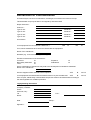
Declaration of Contamination
Of Freeze Dryers, Vacuum-Concentrators, Centrifuges, Accessories and Vacuum Pumps.
This declaration may only be filled in and signed by authorised staff.
Repair Order dtd. :
Order No. :
Type of unit :
Serial No. :
Type of unit :
Serial No. :
Type of unit :
Serial No. :
Type of unit :
Serial No. :
Accessories :
Is the equipment free from harmful substances ?
YES
Ο
NO
Ο
If not, which substances have come into contact with the equipment?
Name of the substances :
Remarks (e.g. to be touched with gloves only) :
General characteristics of the substances :
Corrosive
Ο
Biologically hazardous Ο
Toxic
Ο
Explosive
Radioactive
Ο
Ο
Which combination of substances may lead to the development of hazardous materials?
Name of the substances :
Has the equipment been cleaned before shipment?
YES
Ο
NO Ο
Is the equipment decontaminated and therefore does not pose a health risk?
YES
Ο
NO Ο
Prior to repair, radioactively contaminated components must be decontaminated according to
the valid regulations for radiation protection.
Legally Binding Declaration
I / we hereby declare that the information on this declaration is correct and complete.
Company / Institute :
Street :
Postcode, City :
Tel. :
FAX :
Name :
Date :
Signature :
Stamp :
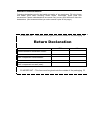
Return Declaration
Following declarations are for the health and safety of our employees. Fill in the forms
and attach them when returning freeze dryers, centrifuges, spare parts and
accessories. Please understand that we cannot carry out any work before we have the
declarations. (We recommend that you make several copies of this page.)
!!!! IMPORTANT – This form must be glued onto the outside of the packaging !!!!
Return Declaration
YES
NO
Decontamination declaration inside :
Unit / component contaminated :
Unit / component unused (new) :
!!!! IMPORTANT – This form must be glued onto the outside of the packaging !!!!