1
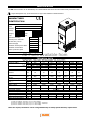
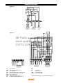
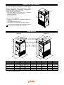
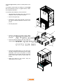
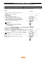
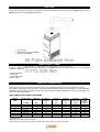
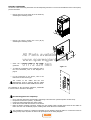
TECHNICAL INFORMATION, INSTALLATION AND OPERATING INSTRUCTIONS Cabinet Warm Air Heater for oil burner BG SERIES All Parts available from www.sparesgiant.com 01772 329 565 Dear Customer, We thank your for having chosen a BG series WARM AIR HEATER: an innovative product, both modern and of high quality, that will ensure you comfort, tranquillity and safety for many years. This in particular if the heater is entrusted to a DESA Italia After-Sales-Service unit, which, with its specifically trained personnel, can maintain the heater at its highest level of efficiency, with low operation costs, and which has original spare parts available, if necessary. This instruction manual contains important indications and suggestions that must be followed to allow an easy installation and an optimum use of the BG series WARM AIR HEATER. Thank you again DESA Italia s.p.a. RANGE In this Manual we refer to the TYPE. The following table shows the range and the correspondence between Type and Commercial Name. TYPE 1 2 3 4 5 6 7 MODEL BG 50 BG 70 BG 90 BG 110 BG 190 BG 260 BG 390 All Parts available from www.sparesgiant.com GUARANTEE 01772 329 565 BG series WARM AIR HEATERS are covered by a SPECIFIC GUARANTEE that starts on the date of purchase of the device, which date the buyer should document; if he cannot do this, the guarantee starts on the date of manufacture of the device. The guarantee conditions are specified in detail in the GUARANTEE CERTIFICATE, supplied with the device, and we suggest you read them carefully. 2 2 INDEX GENERAL INFORMATION: RANGE GUARANTEE INDEX GENERAL NOTES FUNDAMENTAL SAFETY RULES DESCRIPTION OF THE HEATER CONTROL PANEL IDENTIFICATION WIRING DIAGRAM 2 2 3 4 5 6 7 8 9 FITTER: RECEIPT OF THE PRODUCT DIMENSIONS HANDLING AND TRANSPORT POSITIONING MOUNTING THE DISTRIBUTION PLENUM FITTING THE DOUBLE THERMOSTAT SETTING THE DOUBLE THERMOSTAT DUCTING FIXED PROTECTIONS ELECTRIC CONNECTION DISCHARGE OF COMBUSTION PRODUCTS INSTALLATION OF THE BURNER ADJUSTMENTS All Parts available from www.sparesgiant.com 01772 329 565 10 10 11 11 12 14 15 16 16 16 18 19 19 AFTER SALE SERVICE: FIRST START-UP PREPARATION FIRST START-UP CONTROLS CHECKS MAINTENANCE TROUBLE SHOOTING NOTES 21 22 24 24 25 27 30 In some parts of the Manual, we use the following symbols: ATTENTION: For actions that require special care and adequate Preparation. FORBIDDEN: For actions that absolutely MUST NOT be taken. 3 GENERAL NOTES This Instruction Manual is an integral part of the device and as such must always be kept with the device. This is also the case when the heater is sold to another user. The Manual must therefore be conserved and consulted carefully before any action. In the case of damage or loss, you can at any time ask the local After Sales Service for a copy of the Manual. After removing the packaging, first make sure that the contents are complete and undamaged. If the heater does not match with the Manual in any way, contact the Agency that sold the heater. Installation of the BG series WARM AIR HEATER must be carried out by qualified companies under Law 5 March 1990 n°46. On completion of the job, they provide the owner with a declaration of conformity of the correctly carried out installation, that is according to the current applicable Norms requires and according to the indications provided by the Manufacturer in this Instruction Manual. The heaters have been manufactured for room heating and they must be used for this purpose, compatibly with their performance characteristics. The Manufacturer accepts no contractual or extracontractual responsibility for damage caused to people, animals or property, due to errors in installation, adjustment and maintenance or to improper use. Excessive temperature represents a risk for health and a waste of energy. Avoid leaving rooms closed for long periods of time. Open the windows periodically to ensure an adequate air change. During the first start-up, there may be smells and smoke due to evaporation of the liquid used to protect the heat exchanger during storage; this is a normal phenomenon that will disappear after a brief operation time. The rooms must be adequately aerated. On leaving the heater unused for a long period, you should carry out at least the following operations: • Turn off the main heater switch and the main plant switch. • Close the main fuel supply valve. All Parts available from www.sparesgiant.com 01772 329 565 If the heater is not used for a long period of time, we suggest you contact the After Sales Service or other professionally qualified personnel for restarting. All heaters must be fitted exclusively with original accessories. The Manufacturer is not responsible for any damage caused by improper use of the heater and by the use of accessories that are not original. All references to Law, standards, directives and technical rules in this manual are to be considered as informative only and valid at the date of printing of the Manual. The enforcing of new dispositions or the alteration of current ones do not create any Manufacturer obligations towards third parties. Repairs and maintenance must be carried out by the After Sales Service or by qualified personnel as specified in this Manual. Do not alter or tamper with the heater: this can create dangerous situations and the Manufacturer will not be responsible for any damage. The systems that must be installed (oil pipes, electrical supplies, etc.) have to be suitably fastened and must not represent any obstacle that could cause tripping. The Manufacturer is responsible for conformity of his product to laws, directives and instructions standards current at the date of sale. Knowledge and observation of legislative instruments and of standards for the design of systems, and for installation, operation and maintenance are the exclusive responsibility of respectively the designer, the installation personnel and the user. The Manufacturer is not responsible for failure to observe the instructions in this Manual, for the consequences of any operation carried out that is not specifically foreseen, or for any translations causing erroneous interpretations. The heater is designed for operation at the thermal power and the airflow rate as specified in the Technical Data Chapter. A thermal power that is too low and/or an airflow that is too high can lead to condensation in the flue, with consequent irreparable corrosion to the heat exchanger. A thermal power that is too high and/or an airflow that is too low cause abnormal overheating of the heat exchanger with consequent actuation of the safety systems and damage to the heat exchanger. 4 FUNDAMENTAL SAFETY RULES The use of devices that employ electrical energy and/or fuel oil requires the observance of some fundamental safety rules such as: Children ad unassisted disabled persons must not use the warm air heaters. Do not operate electrical equipment such as switches, electric household equipment etc if you can smell fuel or other combustibles. In this case: • Open the doors and windows to aerate the room. • Close the fuel supply valves. • Call in quickly the After Sales Service or other professionally qualified personnel. Do not touch the heater if you are barefoot or if parts of your body are wet. Do not carry out any cleaning or maintenance operation without first deactivating the heater by setting the main system switch to "OFF" and without first closing the fuel supply. Do not alter the safety and adjustment systems without prior authorisation and indications by the heater Manufacturer. Do not pull, detach or twist the electric cables that exit the heater, even if the heater is not connected to the electrical supply. Do not open any doors that access the inside of the heater without turning the main system switch to "OFF". Do not abandon or leave available to children the heater packing materials (cartons, nails, plastic bags, etc.), as these are a potential source of danger. All Parts available from www.sparesgiant.com 01772 329 565 Do not install the heater near flammable material, or in areas where there is a corrosive atmosphere. Do not place any object on the heater or push anything through the grilles in the casing nor in the flue ducts. Do not touch the flue ducts as during normal operation these can reach high temperatures and represent a risk. Do not use any adapters, multiple sockets and cable extensions for the electrical connection of the heater. Do not install the heater in the open air nor where it could be subject to atmospheric events. Do not install the heater directly in limited spaces without adequate ventilation, as the burner air suction can create a pressure drop in the room and consequently cause serious problems. 5 DESCRIPTION OF THE HEATER The warm air heater with fuel oil burner is a device that heats ambient air using thermal energy produced by combustion. An airflow produced by a centrifugal fan is in contact with the heat exchanger wall, so heat is exchanged with no intermediate fluid. The combustion products, after losing heat, are expelled. This system allows considerable reduction of installation and operating costs, and is particularly well suited to applications where use of the heater is intermittent or occasional. During the summer, the heater can also provide ventilation only. GENERAL CONSTRUCTION FEATURES The most important parts of the heater are: • • • • • • • Combustion chamber with flame inversion in stainless steel type AISI 430 resistant to high temperatures, with low thermal loading, of appropriate shape and volume. Tube bundle with oval section fire tubes and turbulence imprints to offer maximum heat efficiency. Flue collector at the rear. Plenum for direct air diffusion with horizontal guide vanes, each separately adjustable, on four sides. Outer casing consisting of removable panels in painted steel sheet. Heat insulation, anti-radiation, for the surfaces exposed to radiation from the heat exchanger. Centrifugal fan, high performance, with double air intake and low sound emission level. The electrical system comprises: Double thermostat Fan-Limit adjusted and electrically connected to offer the following functions: • Function “FAN” (25-35°C), controls the fan start up approximately 60 seconds after ignition of the burner, and stops the fan at approximately four minutes after the burner stops. This avoids the emission of cold air on start-up, and allows the accumulated heat in the heat exchanger to be removed, guaranteeing complete recovery before stopping. • Function “LIMIT” (100°C), with Manual reset, stops burner operation if the air is overheated. • All Parts available from www.sparesgiant.com 01772 329 565 Three way switch to allow heating, ventilation only in summer, and plant stoppage. Type 1÷4 1 2 16 2 2 2 14 15 3 7 8 13 9 12 10 11 6 4 5 1. 2. 3. 4. 5. 6. 7. 8. 5 9. 10. 11. 12. 13. 14. 15. 16. Distribution plenum Air delivery Inspection doors Burner plate Air inlet Flame inspection Double thermostat FAN – LIMIT Chimney connection 6 Combustion chamber Electric centrifugal fan Control panel Casing Front fluegas collector Fire tubes Rear fluegas collector Adjustable vanes Type 5÷7 19 2 20 18 2 8 2 1 7 2 3 17 6 9 4 16 5 5 15 10 11 1. 2. 3. 4. 5. 6. 7. 8. 9. 10. 12 13 14 Distribution plenum Air delivery Inspection doors Burner plate Air inlet Flame inspection Double thermostat FAN – LIMIT Chimney connection Combustion chamber Electric centrifugal fan 11. 12. 13. 14. 15. 16. 17. 18. 19. 20. Fan support plate Transmission belt Motor Belt tightening Control panel Casing Front fluegas collector Fire tubes Rear fluegas collector Adjustable vanes All Parts available from www.sparesgiant.com 01772 329 565 CONTROL PANEL The control panel fitted to the heater allows all operations necessary for system running. 0 FAN - LIMIT 1 0 2 3 TA 288-E 1. 2. 3. Function selector (HEATING / STOP / VENTILATION) Steath gland Cable gland 7 IDENTIFICATION The BG warm air heater can be identified by the Technical Plate that shows the main technical and performance data. It if gets damaged or lost, you should ask for a copy to the Assistance Technical Service. MANUFACTURER IDENTIFICATION WARM AIR HEATER Model Serial Nr Country PIN Code Category Code Type Year Nominal heat rating kW Thermal power delivered kW Air flow-rate (+20°C) m3/h Electrical supply Maximum electric power taken kW Maximum current taken A Electric protection grade All Parts available from TECHNICAL DATA www.sparesgiant.com 01772 329 565 Fuel used: oil Type Total heat rating Heat delivered Efficiency Pressure of the Combustion chamber Combustion chamber volume Net smoke temperature Consumption - Oil (4) Device type Airflow +20°C DT Thermostat settings Operation temperature Electrical supply Engine rating Maximum absorbed current Electric protection degree kW kcal/h kW kcal/h % 1 46,8 40.300 42,2 36.300 90,1 2 71,1 61.200 64,4 55.400 90,5 3 93,0 80.000 83,9 72.100 90,1 4 104,6 90.000 94,2 81.090 90,1 5 190,0 163.400 168,2 144.600 88,5 6 258,8 222.600 230,3 198100 89 7 391,0 336.250 347,6 298.950 88,9 Pa 18 20 25 8 2 39 32 dm3 48,8 77,4 129,5 228,5 490,0 640,0 1050,0 °C 200 220 220 220 249 248 227 kg/h 3,95 6,00 7,84 8,82 16,0 21,8 32,9 6.300 11.500 15.300 23.000 43 45 45 B23 Nm3/ h °K °C °C 2.800 4.500 5.300 43 41 45 kW A IP 0,25 2,6 45 25-35-100 -5/+40 230V 50Hz ~ 0,59 0,73 6,7 7,6 0,73 7,6 2,20 5,1 400V 3N 50Hz ~ 3,00 4,00 7,0 9,1 20 (1) Refers to conditions: 1013 mbar, 15°C, P.C.I. 8570 kcal/m3 (2) Refers to conditions: 1013 mbar, 15°C, P.C.I. 11070 kcal/kg – 5635 kcal/l (3) Refers to conditions: 1013 mbar, 15°C, P.C.I. 10905 kcal/kg – 6285 kcal/l (4) Refers to conditions: 1013 mbar, 15°C, P.C.I. 10200 kcal/kg NOTE: On request, the heaters can be arranged differently to satisfy special efficiency requirements. 8 WIRING DIAGRAM Type 1÷4 CV R FA LM S V FL MG N L 1 2 3 4 5 6 TA IMT G ALIMENTAZIONE ALIMENTAZIONE GENERAL GENERAL ELETTRICA GENERALE BRUCIATORE ELECTRIC SUPPLY ELECTRIC 230V 50HZ 3N 230V SUPPLY 50HZ 3N 230V 50HZ 230V 50HZ Type 5÷7 G All Parts available from www.sparesgiant.com 01772 329 565 RTV R S LX CV LV V FL BC FL FL FL F LM 2 3 4 5 6 R S T N 11 12 TA FA 2 LM 4 5 FA 6 R S T N 11 12 TA ALIMENTAZIONE ELETTRICA ALIMENTAZIONE ELETTRICA BRUCIATORE BURNER 1-PHASE MONOFASE 230V 50HZ BRUCIATORE BURNER 3-PHASE TRIFASE 400V 50HZ 3N ELECTRIC SUPPLY 400V 50HZ 3N ELECTRIC SUPPLY 230V 50HZ G RTV LV CV LX MG LM FA 3 Burner activation line LINEA TERMOSTATICA MG 1 MG 1 BC FL F *TA *IMT Three-phase fan motor Fan motor thermal cut-out Line contactor Function switch HEAT / STOP / VENT Burner thermal safety stop relay Main terminal strip LIMIT thermostat (100°C) Double thermostat FAN (25/35°C) N L1 L2 L3 IMT ALIMENTAZIONE ELETTRICA GENERALE GENERAL 3-PHASE TRIFASE 400V 50HZ 3N ELECTRIC SUPPLY 400V 50HZ 3N Neutral bus Line fuses Auxiliary fuses Room thermostat Differential switch * External to the heater, to be installed by the user. 9 RECEIPT OF THE PRODUCT The warm air heaters are supplied on wooden pallets (bolted to the heater) and are protected by a carton packaging (type 1÷4) or a bubblewrap (for type 5÷7). The following items complete the supply: A plastic envelope (A) containing: • Instruction manual for the plant owner, installation personnel and for the After Sales Service. • Guarantee certificate. • Label with bar code. B A Further and only for type 5÷7: • Diffusion plenum (B) to be assembled and fastened to the heater. • Self threading fastening screws. • Instruction sheet for fitting the air diffusion plenum. The manual is an integral part of the heater and you must therefore read it and keep it with care. DIMENSIONS Type 1÷4 V X Type 5÷7 V Z All Parts available from www.sparesgiant.com 01772 329 565 Z X C C B A Dimensions A B C X V Z Weight (1) B A 1 460 750 1372 228 673 425 112 2 540 800 1472 228 723 505 140 3 680 900 1657 228 823 645 151 4 760 1.080 1772 228 1003 725 214 (1) Net weight without burner. 10 5 900 1300 2120 351 1230 830 437 6 1000 1500 2120 401 1430 930 525 7 1200 1700 2350 451 1628 1130 650 mm mm mm mm mm mm Kg HANDLING AND TRANSPORT Handling must be done by personnel with suitable equipment that has a lifting capacity adequate for the weight of the heater. If a forklift truck is used, widen the forks as far as possible. If a crane is used, hooking points are the eyes placed at the top of the heat exchanger. Type 1÷4 Type 5÷7 ATTENTION Transport and handling must be done very carefully to avoid damage to the heater and danger to persons. All Parts available from www.sparesgiant.com 01772 329 565 During transport and handling operations, do not stand near the heater. If heaters are to be stacked, you must not stack more than one heater on another. Make sure the stacks created are stable by carefully aligning the packages. If a heater is to be moved by hand, make sure you have adequate personnel available with respect to the weight of the heater, as shown in the paragraph “TECHNICAL DATA”, and according to the route to be followed. Wear protective gloves at all times during these operations. POSITIONING The place of installation must be established by the plant designer or by a person competent in this field and must take account of the technical requirements and of applicable Norms and Legislation, as usually specific authorisation are needed (for example: urban planning, architectural rules, fire safety, environmental pollution, etc.). The necessary authorisations should therefore be obtained before installing the heater. For correct installation remember that the heaters must: Be positioned on a surface that is level, dry and able to carry the weight. • Be positioned so that the distances allow correct airflow and allow normal operations of cleaning and • maintenance. • Be at safe distances from flammable materials. • Be near a chimney. • Allow easy maintenance and control operations. • Be placed in areas with ventilation openings according to applicable legislation. Installation is NOT allowed: • • • • • In places where the atmosphere is aggressive. In narrow spaces or where the heater sound emission could be amplified by reverberation or resonance. In corners where there may be deposits of dust, leaves or other materials that could reduce the efficiency of the heater by obstructing airways. Outdoor. In places with pressure drop conditions. 11 Safe distance Installing examples In the middle of the room – 4 sides outlet On a wall 3 sides outlet On a corner 2 sides outlet All Parts available from www.sparesgiant.com 01772 329 565 1 SIDE OUTLET NOT ALLOWED! MOUNTING THE DISTRIBUTION PLENUM The heater is supplied with a distribution plenum that is fitted with adjustable guide vanes. The vanes should be adjusted so that they can ensure a good air distribution: • • • Allow adequate air distribution. Do not create excess resistance to air flow. Do not cause discomfort to people. The vertical airflow guide vanes must be open. They must not be inclined more than 45° with respect to the air flow direction. Air diffusion from one side only of the plenum is not allowed. Guide vanes orientation 12 On models type 1÷4 the plenum is already fitted on the heater. For transport reasons and/or for stacking, on models type 5÷7 the distribution plenum is supplied with the heater but completely dismantled. For assembly and installation, proceed as follows: • After positioning the heater at the area selected for installation, remove the bubble wrap layer. • Remove the supports (1). • Dismantle the grille panel and take out from the fan space the lateral distribution elements of the plenum. • Refit the grille panel. 1 1 3 • 2 Proceed to assemble the angular support panels (2) using the self-threading screws supplied with the heater. All Parts available from www.sparesgiant.com 01772 329 565 • Fasten the diffusion elements (3) using, again, the self-threading screws provided. 2 • Position the assembled plenum on top of the warm air heater, making sure that the hole for the double thermostat, at the top of the plenum, is turned towards the front of the heater (the face where the burner carrier plate and the control panel are located). • Fasten the plenum to the heater using the selfthreading screws provided. 13 3 FITTING THE DOUBLE THERMOSTAT On models type 1÷4 the double thermostat is already fitted to the heater. Models type 5÷7 are supplied with the double thermostat inserted in the seat of the burner plate and electrically connected, to guarantee integrity during transport of the heater with the plenum dismantled. For assembly after installing the plenum, proceed as follows: • 1 Take the double thermostat out of the burner plate by unscrewing and sliding it out. During extraction, pull out the thermostat (1) carefully making sure it remains horizontal, thus avoiding any twisting that could damage it. • Insert the double thermostat in the specific hole (2) at the top of the plenum and fasten it using the screws supplied with the part. • Fasten to the plenum the cable hose collars (3) supplied with the unit. 2 All Parts available from www.sparesgiant.com 01772 329 565 • 3 Fasten the electric supply cable using the specific cable hose collars (4) sited along the right hand side of the heater. The cable hose must be stretched between the collars so that it does not touch hot parts of the casing. 4 Before starting the heater, check the settings of the double thermostat (25-35100°C). 14 SETTING THE DOUBLE THERMOSTAT The heater is supplied with the double thermostat already adjusted according to the following table: FAN Function LIMIT Function 25 – 35°C 100°C If you need to check or re-adjust the thermostat operation settings, observe the following notes. Legend: Type 1÷4 1. White push-button for Automatic-Manual ventilation (if present). 2. Electric connections for FAN function. 3. Graduated scale. 4. Holes for fastening. 5. Fan unit stop temperature indicator. 6. Temperature indicator for LIMIT safety actuation. 7. Slots for cable fastening. Pushing a screwdriver blade in this slot opens the terminal so that the cable can be inserted. On removing the screwdriver blade, the cable is automatically fastened in the terminal. ATTENTION Make sure the cable is tight in the terminal by pulling slightly. All Parts available from www.sparesgiant.com 01772 329 565 Type 5÷7 8. Temperature indicator for fan unit starting. 9. Electrical connections for LIMIT safety function. 10. Red push-button to reset after safety lockout (where present). 11. Metal bridge (where present). ATTENTION On models type 1÷ 4 the metal bridge 11 must be present. On models from type 5 to type 7 the metal bridge 11 must be removed. 15 DUCTING A part of the heated air can be sent via ducting to other rooms using the pre-cut hole (ø 150 for type 1÷2; ø 300 for type 3÷7) at the top of the distribution plenum. 1. Pre-cut hole. 2. Fitting with flange (not supplied). 3. Ducting (not supplied). All Parts available from FIXED PROTECTIONS www.sparesgiant.com 01772 329 565 In order to avoid accidental contact with moving parts, the heater must not be started without any one of the fixed protections, which are: • • • • Lower front panel. Rear panel. Lateral grille panel. Burner cover. ELECTRIC CONNECTION Heaters leave the factory internally wired; they need to be connected according to the wiring diagrams on page 9. The electrical connections must be carried out by professionally qualified personnel and according to current applicable legislation, using the cable grommets on the control panel and the terminals provided. For the size of the supply line, refer to the table shown below. TABLE FOR ELECTRIC SUPPLY LINE SIZING HEATER TYPE Supply Voltage Rating (1) (V-50Hz) (W) 1 2 3 4 5 6 7 230V 3N~ 230V 3N~ 230V 3N~ 230V 3N~ 400V 3N~ 400V 3N~ 400V 3N~ 250 600 730 730 2200 3000 4000 Max current taken(1) Line fuses (2) Auxiliary fuses (2) Conductor section (3)) (A) (A) (A) (mm2) Earthing cable section (3) (mm2) 2,6 6,7 7,6 7,6 5,2 7,1 9,2 10 10 10 10 10 12 16 2 2 2 1,5 1,5 1,5 1,5 1,5 2,5 2,5 1,5 1,5 1,5 1,5 1,5 2,5 2,5 (1) Without burner. (2) Included in the supply fitted to the heater. (3) The section of the supply cables ensures a voltage drop of less than 5% for a length of 30 metres. 16 ELECTRIC CABLE ENTRY The electric cables connecting the heater must be adequately protected. To access the switchboard of the control panel, proceed as follows: • Remove the lower front panel (1) of the heater by slackening the fastening screws. 1 • Remove the electric junction box cover (2) by slackening the fastening screws. All Parts available from www.sparesgiant.com 01772 329 565 • Insert the connection cables in the specific grommets. • To make the connections to the supply line and to the room thermostat, refer to the diagrams on page 9. • For the connections to the burner, refer to the instructions for the burner type. 2 Type 1÷7 0 The section of the cables and the fuse characteristics must be coherent with the TABLE FOR ELECTRIC SUPPLY LINE SIZING shown above. 0 On completion of the connection operations, reassemble in reverse order to the above description. The following points are compulsory: • • • • • Use a multi-pole automatic circuit breaker conforming to CEI-EN norms (contact aperture at least 3mm). Respect the connection L (Phase) - N (Neutral). Protect and fasten adequately the electric cables. Avoid direct contact with hot surfaces on the heater. Make an effective earthing connection, making sure the earthing cable is slightly longer than the line cables so that in the case of an accidental pull, the earthing cable will be the last to be detached. The manufacturer cannot be considered responsible for any damage caused by failure to connect the heater to earth ground) and/or by failure to observe the prescriptions in the wiring diagrams. 17 DISCHARGE OF COMBUSTION PRODUCTS The flue ducts and the connection to the chimney must be built in conformity with current applicable Norms and legislation, using rigid ducting, being resistant to high temperature and to mechanical loads, and gas tight. The correct position for the flue sampling take-off is shown in the drawing. COMBUSTION Punto diPRODUCTS prelievo SAMPLING POINT prodotti combustione Ø 2Ø H TYPE DIMENSIONS Ø H 1 120 1175 1 120 1175 1 All Parts available from www.sparesgiant.com 01772 329 565 Ø H Ø H 120 1175 1 Ø H 120 1175 The chimney must ensure the minimum depression foreseen by current Technical Standards, considering zero pressure at the connection between ducting and chimney (see table page 8). Non insulated flue ducts are a potential source of danger. Chimneys or flue ducts that are inadequately or badly dimensioned can amplify combustion noise levels and have a negative influence on combustion parameters. Joint seals must be made with materials that withstand temperatures of at least 350°C (for example sealants, mastics, silicone products). Avoid or at least limit horizontal ducts that must in all cases be sloped upwards. Use ducts with smooth internal surfaces, in materials that can withstand high temperatures and chemical corrosion by combustion products, of diameter equal to or greater than the flange on the heater. Avoid sharp bends and section reductions. Provide for a stub pipe to allow flue sampling. 18 INSTALLATION OF THE BURNER For installing the burner, making the electrical connections and carrying out the necessary adjustments, refer to the instruction manual supplied with the burner. We suggest that the fuel supply lines be built according to the figures here beside. For oil versions an adequate filter must be provided in the fuel suction line. ADJUSTMENTS BURNER COUPLING TABLE The burners that can be used for best heater performance are the following: RIELLO Oil Burners: Type 1 2 3 4 5 6 7 Burner Model REG 5 R40G10 RG2 R40G10 RG2 R40G10 RG2 R40 G20 RG 4S RL 28 tc RL 28/1 tc RG 5 S RL 38 tc RL 34/1 MZ tc Burner Code 3772200 3452021 3737700 3452021 3737700 3452021 3737700 3452731 3739600 3473207 3472003 3739900 3474107 3470100 Nozzle 60°W (G.P.H.) n°1x1,00 n°1x1,50 n°1x1,50 n°1x1,75 n°1x1,75 n°1x2,00 n°1x2,00 n°1x3,50 n°1x3,50 n°2x2,25 n°2x2,25 n°2x2,25 n°2x3,50 n°2x3,50 Nozzle Code 1825027 1825037 1825028 1825037 1825033 1825037 1825022 1825026 1825024 1825023 1825023 1825023 1825024 1825024 All Parts available from www.sparesgiant.com 01772 329 565 Electric supply 230V 50Hz~ 230V 50Hz~ 230V 50Hz~ 230V 50Hz~ 230V 50Hz~ 230V 50Hz~ 230V 50Hz~ BURNER ADJUSTMENT Only qualified personnel can fit and adjust the burner, holding strictly to the instructions in the Burner Manual. NB: The adjustment of combustion air varies according to the characteristics of the chimney, and is done by acting on the specific damper according to the instructions in the Burner Manual. 19 IMPORTANT If the heater is replaced, but the existing burner continues to be used, make sure that: • The performance of the burner is coherent with that required by the heater. • The length and diameter of the burner sleeve correspond to the dimensions shown in the Table. DIMENSIONS P Ø max TYPE 1 80 120 2 80 120 3 80 220 4 80 170 5 150 170 6 130 220 7 130 220 If the length is greater, the length must not be more than 20% greater than the value shown. All Parts available from www.sparesgiant.com 01772 329 565 20 mm mm FIRST START-UP PREPARATION Before starting and testing warm air heaters, check that: • The protective film has been removed from the heater walls. • The air guide-vane orientation has been adjusted according to the position of the heater and to the needs of the room. 45° mimino Use adequate safety equipment (gloves etc.). You must open the air deflectors before installation. Open the deflectors by taking hold of the ends. • The heater is correctly positioned and the distances around the heater have been respected (see page 12). • There is fuel available and the supply valves are open. • The electrical connections to the supply and to the components (burner, thermostats, etc) have been made. All Parts available from www.sparesgiant.com 01772 329 565 The phase - neutral connection must be absolutely respected. The earthing connection is obligatory. 21 FIRST START-UP After carrying out the preparation operations for the first start-up, to start the warm air heater you must: Position the plant main switch to “ON”. • Activating the “VENTILATION” function – Set the function switch (1) to “VENTILATION” ¤. The burner remains off and only the centrifugal fan will start to circulate the room air at the inlet temperature. During the first start-up there might be the presence of odours and smokes caused by the evaporation of the fluid used to protect the heat exchanger during the storage period. It is a normal condition that will disappear after a short period of operation. It is recommended to air the served rooms. • Disabling the “VENTILATION” function – Set the function switch (1) to “0” (OFF). The centrifugal fan switches “OFF”. • Activating the “HEATING” function – Adjust the room thermostat temperature (e.g. 18°C). to the – Set the function switch (1) to “HEATING” required . All Parts available from www.sparesgiant.com 01772 329 565 The heater will go through the first stage of start-up and approximately one minute after flame ignition, the fan will start, delivering warm air to the room to be heated. The heater will remain in operation until the required temperature is reached; then, the contact on the room thermostat opens, the burner stops and after a few minutes (approximately four) the fan also stops. Successive re-starts and stops are automatic according to the temperature set, with no need for further action. 1 • Disabling the “HEATING” function – Act on the room thermostat or position the function swtich (1) on “0” (OFF). The burner stops immediately and after about 4 minutes the fan stops too. Never turn off the heater by removing the electrical supply before the fan stops; this to avoid dangerous overheating and actuation of the LIMIT thermostat. 22 0 In case of wrong switching on or working the generator will be able to make two different stop: 1. “BLOCK”, signalled by the luminous red push-button on the burner. After a “BLOCK” wait approximately 30 seconds before resetting starting conditions. To reset the starting conditions press the luminous burner push-button and wait for the flame to ignite. If restarting fails, this operation can be repeated 2-3 times at most, then check: • • • The instructions contained in the burner manual. The Chapter “Preparation for the first start-up”. The electrical connections. 2. “OVERHEAT SAFETY STOP” After an “OVERHEAT SAFETY STOP” wait approximately 10 minutes before resetting the starting conditions, or turn on the ventilation function (page 21) to reduce the waiting time. All Parts available from www.sparesgiant.com 01772 329 565 – Press the reset button (1) on the LIMIT thermostat. Or – If the fan motor cut-out switch RTV has actuated, reset by pressing the specific button inside the control panel switchboard (only on types 5÷7). If this action fails, the operations can be repeated 2-3 times at most; then check: • • • The Chapter “PREPARATION FOR THE FIRST START-UP”. The electrical connections. The Chapter “CHECKS”. 23 CONTROLS ROOM THERMOSTAT This must be installed in the room to be heated at a height above floor level of 1.5 m approximately, in a position protected from currents of hot or cold air. The thermostat controls start-up and stoppage of the heater to maintain the temperature near the value set. The thermostat is not supplied with the heater but must be requested as an accessory. OPERATION SWITCH HEATING/STOP/VENTILATION Placed on the heater control panel, this switch allows selection of the operation cycle: • • • Set to the symbol “heating", it programmes the heater so that the fan and the burner operate automatically according to the heat demand. Set to the symbol “ventilation", it controls the heater excluding operation of the burner thus, operating with the fan only, it allows summer cooling. Set to the symbol “stop”, it stops the warm air heater. The fan operates for a certain time to remove the heat accumulated in the heat exchanger. CHECKS To ensure correct operation of the heater, some fundamental parameters must be checked. Switch on the heater and: • Check that the fan unit starts approximately one minute after burner ignition. All Parts available from www.sparesgiant.com 01772 329 565 With the warm air heater in steady state (after approximately 20 minutes of continuous operation) carry out these operations: • • • • • • • • • • • • Check that there are no fuel leaks. Check the correct flow rate of the fuel measured at the counter (where possible). Check that the settings of the double thermostat are as indicated in the Chapter TECHNICAL DATA. Check that the flue temperature is as shown in the Chapter TECHNICAL DATA, with a tolerance of +/-10°C. Check that the double thermostat adjustments are as shown in the Chapter TECHNICAL DATA. Check that the graduated dial of the double thermostat indicates 50-60°C and that the LIMIT switch does not operate. Check that the temperature difference Dt between air delivered (Tm) and air returned (Tr) corresponds to that indicated in the Chapter “TECHNICAL DATA” with a tolerance of ± 5°C. Turn the double thermostat dial by hand to simulate action of the LIMIT thermostat and check that the burner switches off. Open the contact in the room thermostat and check that this acts on the burner only and that the fan unit does not stop at the same time. Check that the current taken by the main motor does not exceed nominal value on the number plate. Check that the setting of the cutout protection relay is adjusted to the nominal current value of the motor (only for types 5÷7). Check that the fan operates for approximately four minutes after the burner is switched off, before stopping. IMPORTANT 24 • An excessively low thermal power and/or an excessively high airflow rate can cause condensation of the flue, with consequent irreparable corrosion of the heat exchanger. • You MUST check for the absence of condensation within the heat exchanger during operation. This check is done by switching the burner off after approximately ½ hour of continuous operation, at the same time checking via the chimney connection that there is no trace of humidity in the flue collector and in the fire tubes. MAINTENANCE For good heater operation and conservation, we recommend you carry out periodical cleaning and maintenance operations. Any operation of this type must be carried out by specialised personnel qualified for the function. The operations must be done when the heater has cooled down, turning off both the electrical and the fuel supplies. HEAT EXCHANGER CLEANING Cleaning the heat exchanger must be done by qualified personnel, and is regulated by specific prescriptions. The operation should be done at least once a year, at the start of the winter season, proceeding as follows: Type 1÷2 Type 1÷4 – – Clean the internal surfaces of the heat exchanger (3) using brushes or other tools of suitable shapes and sizes. – Remove the deposits that accumulate in the combustion chamber (8) using a vacuum system through the burner opening (9). – Remove the deposits accumulated in the rear fluegas collector (4) using a vacuum system through the chimney connection (5) (only for models type 1÷2). Type 5÷7 2 5 1 8 All Parts available from www.sparesgiant.com 01772 329 565 – Remove the inspection panel (1), the inspection door (2), and the burner following the indications in the specific manual. – Clean the internal surfaces of the heat exchanger (3) using brushes or other tools of suitable shapes and sizes. – Remove the deposits accumulated in the combustion chamber (8) using a vacuum system through the burner opening (9). – 3 4 Remove the inspection panel (1), the inspection door (2) and the burner following the indications in the specific manual, and extract the diaphragm (only for models type 1÷2). Type 3÷4 2 1 3 9 Type 5÷7 Remove the deposits accumulated in the rear flue collector (4) using a vacuum system through the lateral inspection openings (10). 7 4 3 6 10 6 We suggest the use of protective gloves; when using ladders or other means of access, all operations must be carried out using suitable systems, in conditions of complete safety. 1 2 25 2 9 8 7 PERIODICAL FAN MAINTENANCE Type 1÷4 The motor is connected directly to the fan shaft. The fan motor does not need any maintenance, but only periodical cleaning. Type 5÷7 Cleaning the centrifugal fan requires mechanical removal of dust and of any extraneous bodies deposited on or near the rotor. Periodically check the transmission belt tension. When pressing at the centre, it should deflect by approximately 20mm. Adjust if necessary as follows: • • • • • Turn the generator off by setting the main switch on the control panel to “OFF”. Remove the protection grille. Slacken the four nuts (3) that fasten the motor support. Tighten the belt (1) by acting on the screws (2), until, when pressing at the centre, the belt deflects approximately 20mm. Tighten the four nuts (3) to fasten the motor support. Check that the motor and fan pulleys are aligned correctly. For these models too the fan motor does not require maintenance but only periodical cleaning of the protective cover of the cooling fan. THERMOSTATS Type 5÷7 All Parts available from www.sparesgiant.com 01772 329 565 The thermostats do not require maintenance save normal cleaning of the external parts of the sensitive elements. The LIMIT thermostats have fixed settings and must not be tampered with. The FAN thermostats are pre-set during manufacture and we suggest you do NOT adjust their settings. The manufacturer is not responsible for any damage caused by improper actions on the thermostats. BURNER CLEANING For burner cleaning, refer to the instructions in the burner manual. 26 TROUBLE SHOOTING ANOMALY CAUSE THE GENERATOR DOES NOT WORK EITHER IN VENTILATION OR IN HEATING THE GENERATOR DOES NOT WORK IN SUMMER VENTILATION REMEDIES No energy supply Check electric connections Check the line and auxiliary load fuses No energy supply to the fan motor Check electric connections Check line and auxiliary load fuses Check for actuation of the motor thermal cut-out (only for three-phase versions) THE GENERATOR DOES NOT HEAT No energy supply to the oil burner Check electric connections Check the line and auxiliary fuses Check that the room thermostat contact is closed Check for actuation of the motor thermal cut-out (only for three-phase versions) Check for actuation of the LIMIT thermostat THE BURNER FLAME IGNITES BUT GOES OUT AFTER A FEW SECONDS Electric connection not correctly made Burner to be checked or faulty Check supply polarity (phase + neutral + earth) All Parts available from www.sparesgiant.com 01772 329 565 Check burner settings Replace the electronic burner control device Check and / or replace the flame detector electrode THE OIL BURNER FLAME IGNITES BUT GOES OUT AFTER A FEW SECONDS Electrical connection not made correctly Burner to be checked or faulty Check supply polarity (phase + neutral + earth) Check burner settings Replace the electronic burner control device Check and/or replace the Burner photocell 2 27 ANOMALY CAUSES THE BURNER GOES OUT ANOMALOUSLY AND BY CHANCE Actuation of the LIMIT thermostat REMEDIES Check the aperture of the air flow direction control vanes Check for the absence of obstructions on the air inlets Check the fan motor Flame detaches from burner Check burner settings Check that the generator is not in a room subject to pressure drop LIMIT THERMOSTAT OPERATES Room thermostat not correctly installed Check that the sensitive element of the room thermostat is not in the flow of hot air from the generator Obstructions in the air circuit Check that the airflow control vanes are open Check for the absence of obstructions on the air inlet grilles Check the aperture of the airflow control vanes so that there is no backflow of hot air to the inlets. Hot air backflow Check the temperature of the inlet air Fan assembly to be checked or faulty Check that the fan rotor is clean All Parts available from www.sparesgiant.com 01772 329 565 Check the efficiency of the fan motor Check the state and tension of the belts (three-phase version only) Check for anomalous action of the motor thermal cut-out (three-phase version only) Excess thermal power FAN MOTOR THERMAL CUT-OUT ACTUATES (ONLY FOR THREEPHASE VERSIONS) Excess current intake and/or heating of the fan motor Check the settings of the oil burner Check that the air distribution plenum is installed Check the electric supply voltage Check the inlet air temperature THE FAN DOES NOT START WITHIN APPROX A MINUTE AFTER BURNER IGNITION Insufficient thermal power Check the oil burner settings Double thermostat FAN-LIMIT to be checked or faulty Check the FAN settings Replace the double thermostat FAN-LIMIT 28 ANOMALY CAUSES THE FAN DOES NOT STOP WITHIN FOUR MINUTES OF BURNER STOP Room temperature too high REMEDIES Check the inlet air temperature Check for any exposure to sunlight Double thermostat FAN-LIMIT to be checked or faulty Check the FAN settings Check the white push-button in AUTOMATIC position Replace the double thermostat FAN-LIMIT THE FAN DOES NOT OPERATE Fan unit to be checked or faulty Check the efficiency of the fan motor Check the efficiency of the fan motor condenser (single phase versions only) Check the transmission belts (three-phase versions only) Check for action of the fan motor thermal cut-out (three-phase versions only) Double thermostat FAN-LIMIT to be checked or faulty Check the FAN settings Replace the double thermostat FAN-LIMIT THE FAN OPERATES INTERMITTENTLY Double thermostat FAN-LIMIT to be checked or faulty Check the FAN settings Replace the double thermostat FAN-LIMIT THE FAN HAS SOME IDLE OPERATION Insufficient thermal power Hot air backflow All Parts available from www.sparesgiant.com 01772 329 565 Check the oil burner settings Check the aperture of the air flow control vanes, so that there is no backflow of hot air to the inlets Check the inlet air temperature Check the oil burner settings and cleaning Chimney blocked Clean the flue duct and the chimney INTERNAL CONDENSATION OF COMBUSTION PRODUCTS Insufficient thermal power Check the oil burner settings DIFFICULTY IN REACHING THE TEMPERATURE SET ON THE ROOM THERMOSTAT Insufficient heat exchange due to fouled heat exchanger Clean the heat exchanger Check the oil burner settings Check that the room thermostat bulb is not in the generator hot air flow THE GENERATOR GETS UNUSUALLY DIRTY Burner settings incorrect Burner not set correctly Room Thermostat not installed correctly PRODUCT DISPOSAL This product was designed and made with high qualità material and components which can be recycled and reused. When finding the symbol of a wheeled crossed bin on a product, be aware of the fact that the component is covered by the European Directive 2002/96/EC. Get informed about your local waste separation system as far as electric and electronic products are concerned. Respect your in force local rules and do not dispose old products with your household waste. A correct product disposal helps preventing possible negative consequences on human and environmental health. 2 29 NOTES All Parts available from www.sparesgiant.com 01772 329 565 3 30 EC CONFORMITY DECLARATION DÉCLARATION DE CONFORMITÉ À LA CE EU-ÜBEREINSTIMMUNGSERKLÄRUNG CONFORMITEITSVERKLARINGVOOR DE EU DICHIARAZIONE DI CONFORMITÀ DECLARACION DE CONFORMIDAD CON LA CE FÖRSÄKRAN OM ÖVERENSSTÄMMELSE EU:N VAATIMUSTENMUKAISUUSVAKUUTUS EU OVERENSSTEMMELSESERKLÆRING EU-SAMSVAR DEKLARACJA ZGODNOŚCI WE ЗAЯBЛEHИE O COOTBETCTBИИ TPEБOBAHИЯМ CTAHДAPTOB EC EC MEGFELELŐSÉGI NYILATKOZAT PROHLÁŠENÍ O DODRŽENÍ NAŘÍZENÍ EC EC ATITIKTIES DEKLARACIJA EL VASTAVUSAVALDUS EC ATBILSTĪBAS DEKLARĀCIJA ΔΗΛΩΣΗ ΣΥΜΜΟΡΦΩΣΗΣ ΕΚ AT UYGUNLUK BEYANI VYHLÁSENIE ZHODY S ODPORÚČANIAMI EURÓPSKEHO SPOLOČENSTVA DECLARAŢIA DE CONFORMITATE CU RECOMANDĂRILE COMUNITĂŢII EUROPENE ДЕКЛАРАЦИЯ ЗА СЪОТВЕТСТВИЕ НА ЕВРОПЕЙСКАТА ОБЩНОСТ DEKLARACIJA USKLAĐENOSTI S PREPORUKAMA EUROPSKE UNIJE ДЕКЛАРАЦІЯ ВІДПОВІДНОСТІ EC DESA ITALIA s.p.a. Via Tione, 12 - 37010 - Pastrengo (VR) ITALY Portable forced air heaters: - Appareils de chauffage individuels à air forcé: - Tragbare hochdruck-heissluftturbinen: - Mobiele ventilator-luchtverwarmer: - Generatore d’aria calda: - Calentadores móviles de aire forzado: - Portabel värmefläkt med forcerat luftflöde: - Siirrettävä kuumailmapuhallin: - Flytbare luftcirkulations apparater: - Flyttbar varmekanon: - Przenośne nagrzewnice powietrza pod ciśnieniem: - Тепловой генератор: - Hordozható hőlégfúvók: - Přenosná topná tělesa na dm chan vzduch: - Kilnojami aukšto slėgio oro šildytuvai: - Kaasaskantav õhusoojendi: - Pārvietojamie gaisa sildītāji ar piespiedu gaisa padevi: - Φορητη θερμαστρα εξαναγκασμενησ ροησ αερα: - Priprava za vpihavanje toploga zraka: - Portatıf basinçli hava isiticilar: - Prenosný tlakový teplovzdušný ohrievač: - Încălzitoare portabile de aer: - Преносими отоплители под налягане: - Uređaj za upuh toploga zraka: Портативні повітрянагрівачі: All Parts available from www.sparesgiant.com BG 50 - BG 70 - BG 90 01772 329 BG 110 - BG 190 565 - BG 260 - BG 390 It is declared that these models conform to: - Ces modèles ont été déclarés conformes à: Hiermit wird bescheinigt, daß diese Modelle in Übereinstimmung: - Hierbij wordt verklaard dat deze modellen: Si dichiara che questi generatori sono conformi: - Se declara por este medio que estos modelos: Ovanstående modeller överensstämmer: - Näiden mallien todistetaan täten noudattavan: Det attesteres herved, at anførte modeller er i overensstemmelse: - Det erklæres at disse modellene er i samsvar: Oświadcza się, że niniejsze modele zgodne są z zarządzeniem: - Hacтoящим мы зaявляем, что эти нагрeвaтели oтвечают требованиям стандартов на оборудование: - Kijelentjük, hogy fenti modellek megfelelnek Prohlašujeme, že tyto modely odpovídají Nařízení pro stroje: - Vastab järgmistele el direktiividele ja standarditele: Atbilst sekojošu es standartu un direktīvu prasībām: - Δηλώνεται ότι αυτά τα μοντέλα είναι σε συμμόρφωση με την οδηγία περί Μηχανημάτων: - İşbu modellerin: - Potvrdzujeme, že tieto modely sú zhodné s nariadením: - Declară că modelele sunt produse conform hotărârii: - Декларира, че горепосочените модели съответстват Директивата за: - Očituje se da su spomenuti modeli sukladni sa uredbom: - Декларується що ці моделі відповідають: 98/37 CE, 91/368, 93/44, EMC 89/336, 92/31, 93/68, 73/23 Pastrengo, 06/04/2010 Raffaele Legnani (Managing Director) All Parts available from www.sparesgiant.com 01772 329 565 DESA ITALIA s.p.a. DESA POLAND Sp. Z.o.o DESA HEATING EQUIPMENT SHANGHAI CO., LTD Via Tione, 12 – 37010 ul Magazynova 5A, 62-023 Rm. 2203, 218, HengFeng Rd, Pastrengo (Verona) – Italy Gadki, Poland Shanghai, China, 200070 www.desaitalia.com www.desapoland.pl www.desa-china.com [email protected] [email protected] [email protected] 02/10_Rev.0 Cod. 745-MN 2