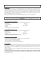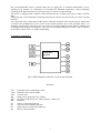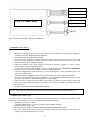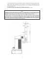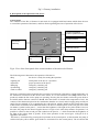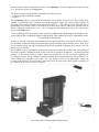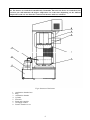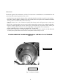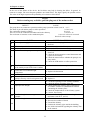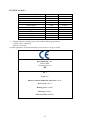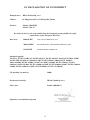
1
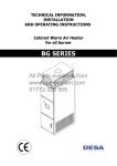
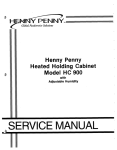
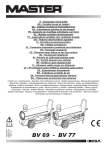
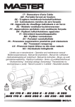
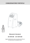
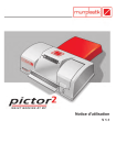
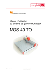
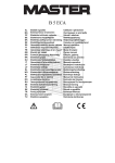
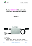
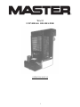
WA 33
UNIVERSAL OIL HEATER
OPERATING MANUAL
aryjnąależy dokładn
1. Przeznaczenie
1
In order to ensure proper use and fault-free operation of the furnace, read this manual carefully.
1. Destination
The WA 33 universal oil heater is intended for heating the industrial rooms which are not included in the
central heating system (workshops, car maintenance services, industrial halls, warehouses, inventory
buildings, basements, garages, etc. The furnace may operate with the use of most mineral and plant oils
such as, for instance, engine oils, fuel oils, gear oils, hydraulic oils, oils of HBO I, II, III type with the
maximal kinematic viscosity of 6.00 mm²/s at the temperature of 20ºC, flash-point temperature not lower
than 40ºC and thickness not less than 0.94 g/cm³.
Due to the local regulations, it is recommended to apply the diesel oil, fuel oil or biodiesel oil.
DO NOT APPLY TRANSFORMER OILS
THEY MAY CONTAIN SUBSTANCES DETRIMENTAL TO THE OPERATION OF THE
FURNACE
2. Environmental storage conditions
The WA 33 universal oil heater should be stored in the following conditions:
• temperature
-20..85°C
• relative humidity
5..85%
• pressure
800..1200hPa
• dust-free
• environment free from chemical pollution.
3. Environmental conditions of use
The WA 33 universal oil heater should be used in the following conditions:
• temperature
0..30°C
• relative humidity
5..85%
• pressure
800..1200hPa
• protection level against the environmental impact
IP20
• good ventilation of the heated room.
4. Characteristics of the controller
• possibility to adjust the furnace power within the range of 22 and 30 kW,
• protection of the furnace against overheating,
• protection against oil overflow in the furnace,
• automatic maintenance of settings at the voltage decay,
5. Safety aspects
The WA 33 universal oil heater is supplied from the 230V, 50Hz alternating current mains. A fuse with a
fuse-element (1A, 250V) has been installed on the housing of the control module. The replacement of this
fuse should be carried out unconditionally when the external power supply of the system (230V AC,
50Hz). is cut-off.
The WA 33 universal oil heater is equipped with two bimetallic sensors ensuring safe and economical
operation of the device.
The bimetallic sensor placed in the furnace chamber reacts by opening contacts, when the temperature
drops below 35°C. In the emergency situations (overheating, oil overflow) the processor checks the signal
from the bimetallic sensor and switches on the exhaust fan until the furnace is cooled off to the
temperature below 35°C.
2
The second bimetallic sensor is placed nearby the air supply fan, its threshold temperature is 90°C.
Opening of its contacts, in consequence of exceeding the threshold temperature, causes immediate
switching of the furnace into the Overheating mode (see section 8 of this manual).
The heater is equipped with a balance sensor placed below the overflow tank (the so called, overflow
fuse).
Filling this tank causes immediate switching of the furnace into the Overflow mode (see section 8 of this
manual).
The connection of the control panel of the furnace with other elements of the system (sensors, pump, fan)
is made by the manufacturer, in the course of the normal operation, due to the operation safety, it is
absolutely not allowed to interfere in any way in the covered and sealed part of the furnace controller and
to infringe on the integrity of conductors. Any action of an unauthorised person creates a risk of exposure
to the electric shock (230V AC, 50Hz) and burning.
6. Structure of the device
Controller
module
Fig. l. Block diagram of the WA 33 universal oil heater
Notations:
T40
T100
OVF
MP
MW
KB
Dl
D1
D3
D4
bimetallic furnace temperature sensor
bimetallic safety sensor (STB)
overflow fuse
pump (power 48W [230V AC, 50Hz])
fan (power 35W [230V AC, 50Hz], capacity - l000 m³/h)
keyboard
furnace overheating indicator
overflow tank overfilling indicator
pump motor revolving speed indicator
furnace off/on indicator
3
Furnace thermnostat
Safety thermnostat (STB)
Overflow fuse
WA 33 controller
Fan
Pump
Fig.2. Furnace controller –group of conductors
7. Installation of the device
-
during the installation of the device, meet all the local regulations, including the regulations
referring to the national and European standards
place the furnace on a flat concrete ground
level the device. In order to check whether the heater is levelled, place the furnace pan in the
lower part of the combustion chamber and pour a small amount of diesel oil on it. The oil should
spread accurately in the middle of the pan.
mount the stabiliser on the pipe coming out from the combustion chamber in order to ensure
stable draught during the heater operation.
in order to ensure the optimal draught, install a vertical chimney pipe (not made of aluminium)
which is at least 6 meters long, smooth, resistant to high temperature
check the leakproofness of all connections, in case of emergency, use the insulation tape for the
purpose of sealing them
make sure that the combustion pan is placed in the central part of the combustion chamber
place the top ring inside the combustion chamber – the edging in the middle of the ring is placed
upwards, - and mount an afterburner cylinder on it (hot air pipe)
check the mains voltage (220-240V/50Hz) and connect the furnace to power supply, neither the
fan nor the pump should be started as the furnace has not been switched on yet and no heat has
been produced.
maintain a safe distance from inflammable materials
The air exhaust fans operating in the same room or space as the device may introduce disturbances.
Assembly of the chimney pipe
In order to ensure proper burning, it is necessary to provide the properly made chimney installation. The
following recommendations must be met while providing this installation:
- minimal pipe diameter: 150mm
- check the leakproofness of connections between the chimney elements
- minimal chimney height: 6m
- the section of the chimney inside the chimney should be insulated (dual wall)
- the wind should freely blow around the chimney outlet from all directions (the end of the
chimney pipe should be above the roof top)
4
-
-
if possible, all the chimney section should be vertical – avoid horizontal sections as well as bends
of the chimney pipe, if necessary (e.g. two bends in case the pipe is run through the wall or
window, then the maximal deflection angle amounts to 45°, the minimal chimney height should
be increased up to 7m
the minimal chimney flue draught 16Pa at nominal heating power
the device may not be connected to the joint exhaust fumes discharge system
NOTE
Mounting the exhaust fumes discharge system, it is recommended to avoid horizontal sections of
the chimney pipe system. In order to ensure the free gas outflow, the angle of the possible pipe bend
should not be greater than 45°. The chimney outlet must be higher than the roof top.
The places where it runs through the ceiling, walls or roof must be insulated to avoid fire hazard. It
is recommended to use the dual wall insulated chimney pipe in all places where there is a possibility
of the touch contact, as well as outside the building, to ensure good draft and prevent condensation.
Do not place any materials nearby the furnace, even the non-flammable ones. Ensure permanent
access or air, necessary for the proper combustion process.
5
Fig.3. Chimney installation
8. Description of the operation of the device
Control panel
The controller of the WA 33 furnace for universal oil is equipped with four buttons which allow the user
to control the operation of the heater, and four diodes signalling the state of operation of the device.
Furnace overheating
indicator (STB thermostat)
Straight-through pan
overflow indicator
Adjustment of
the furnace
efficiency
Furnace operation indicator
Furnace operation
readiness indicator
Furnace switchkey
Furnace breaker
switch
LED diodes
Fig.4. View of the front panel of the control module of the universal oil heater.
The following states characterise the operation of the device:
•Stop
•Lighting off
•Operation
•Damping
•Overheating
•Tank overflow
the device is ready for starting the operation
initial phase of the device’s operation
proper operation of the device
emergency switching off
emergency switching off
emergency switching off
The heat is generated owing to burning the gas which is produced by oil heated to a high temperature. At
the moment of connection of the device to the mains, it is in the readiness state (Stop) and no heat is
produced, neither the fan nor the pump are operating. Pressing the Start button causes the green diode to
be backlit and the furnaces switches to lit off. After the furnace is heated to the temperature of 40 C the
contacts of the thermostat placed at the combustion chamber are closed, and oil supply pump and the air
supply fan are switched on. It is signalled by the yellow diode, which is backlit on the control panel. Due
to the smaller oil demand at the unheated furnace, the devices should operate on the first gear for at least
30 minutes (symbol on the panel „-„ means that the brightness of the light of the yellow diode is low).At
this time, the pump for the furnace supplies about 1.85 kg/h of oil. After thirty minutes of operation, it is
possible to switch on the second gear (the symbol on the panel is „+” which means that the brightness of
the light of the yellow diode is greater). At the time operation on the second gear, 2.55kg/h of oil is
supplied to the furnace.
The heater is switched off by pressing the Stop button on the control panel. At this moment, the pump is
switched off (the yellow and the green diode are switched off on the control panel). The air exhaust fan
6
operates until the furnace temperature is below 35°C (damping). After the temperature reaches less than
35°C, the furnace returns to the Stop phase.
The furnace may be switched off automatically in the following cases:
- overheating of the combustion chamber
- overflow
The overheating signal is generated by the bimetallic sensor placed nearby the fan. The opening of the
contacts is signalled by the exceeding the threshold temperature value. The control system switches off
the pump (the operation indicator of the pump is not back-lit – yellow diode), the overheating state is
signalled by the red diode, which is back-lit on the control panel. The air exhaust fan operates until the
furnace temperature drops below 35°C. After reaching the temperature lower than 35°C, the furnace
returns to the Stop phase.
After switching to the Stop phase (and even after switching off and then again switching on the
power supply) the overheating signal is still back-lit. This enables the user to establish the cause
of switching off the furnace.
In order to clear the overheating signal and return to the normal operation, wait until the furnace is cooled
off (switching off the fan) and press the button placed on the housing of the bimetallic sensor. Then, press
the Start button, which will cause the lighting of the diode signalling overheating to be switched off. The
furnace may be restarted.
The overflow signal is generated by a mechanical sensor placed under the overflow tank. The opening of
the contacts signals overfilling the tank. At the same time, the pump is switched on – the pump operation
indicator is not back-lit anymore (yellow diode) and instead, the relevant red diode signifying the
overfilling is back-lit. The air exhaust fan operates until the furnace temperature below drops below 35°C.
After reaching the temperature lower than 35°C, the furnace returns to the Stop phase. Empty the
overflow tank, and press the Start button, which will cause the (red) diode, which signals overfilling, to
be switched off. The furnace may be restarted..
Fig.5. Placement of elements protecting the heater:
7
1.Thermostat at the combustion chamber 2. Protection against overheating 3. Overflow protection
9. Operation of the heaters
NOTE
YOU MUST NOT ADD OIL TO THE FURNACE AND FIRE IT WHEN
THE CHAMBER OR PAN OF THE FURNACE IS STILL HOT!!!
ALWAYS WAIT UNTIL THE BURNER PLATE IS TOTALLY COOLED
OFF. FAILURE TO OBSERVE THE ABOVE-MENTIONED
RECOMMENDATION CREATES A RISK OF UNCONTROLLED
IGNITION OF OIL VAPOURS AND BURNING!!!
Starting the device
After the heater, it goes through the respective operating conditions depending on the settings introduced
by the user and the information received from the sensors attached to the controller system.
- in case of emergency, discharge the water from the fuel tank and fill it in with used oil
- put the plug of the power cable into the mains socket (230V 50Hz)
- open the top part of the heater housing and remove the cover of the combustion chamber, then take out
the cylinder and ring (in the case of necessity, clean the combustion pan and base on which it is placed,
but also the whole combustion chamber with a sleeve and the ring)
- check whether the furnace pan is cool and clean, then pour about 250 ml of fuel oil or diesel oil
- fire the oil, using a piece of paper which is crumpled into a ball for this purpose. the piece of paper must
be set afire and thrown onto the furnace pan
- mount the ring and the cylinder, place the combustion chamber cover, close the top part of the heater
housing
- press the Start button on the control panel (a green diode will be back-lit)
- after about 10-15 minutes, depending on the room temperature, the fuel pump and the fan will be
switched on, and at the same time, the yellow diode for pump operation will be back-lit, the furnace
will start to operate on the first gear with a decreased efficiency (22 kW; burning 1.85 kg/h), it may
operate continuously in this condition, the second gear with an increased efficiency (30 kW: burning
2.55 kg/h) may be switched on (marked with ”+” symbol) after 30 minutes from the start of the
operation of the furnace.
Each pressing the Stop button and pressing the Start button again and again during its
operation will cause the furnace to be lit off.
Switching off the device
- press the Stop button on the control panel (the yellow diode is not back-lit anymore), the pump stops
supplying fuel on the combustion pan, the fan operates until the furnace is cooled off.
8
Do not connect the device to the mains, when the fan is in operation, wait until the furnace is cooled
off. The furnace is switched off automatically. Remember that after the device is switched off, the
cast-iron pan still maintains the higher temperature for some time (depending on the ambient
temperature) and it is not allowed to switch on the furnace until it is cooled off
Fig.6. Structure of the heater
1.
2.
3.
4.
5.
6.
7.
8.
combustion chamber base
Ring
combustion chamber
Cylinder
Fuel tank
Pump and controller
Oil supply conduit
Furnace chamber cover
9
Maintenance
The heater requires little maintenance activities. The observance of manufacturer’s recommendations will
ensure fault-free and safe operation of the device.
- clean the furnace pan and the elements of the combustion chamber (cylinder, ring and cover) everyday
- check the overflow conduit is jammed or not (the conduit in the lower part of the combustion chamber,
directly over the overflow tank), clean if necessary
- clean the furnace base in the combustion chamber (the element under the furnace pan) at least once a
week
- check if the air inlet openings are not covered in the bottom and the top part of the combustion chamber
- clean the conduit supplying oil onto the furnace pan, the maximal time of operation of the furnace pan
without cleaning amounts to about 7-14 hours (depending on the applied oil for combustion)
- during the heating season, clean the fuel tank and the oil pump filter
- if the furnace is inoperable for a longer period of time, clean the combustion chamber and the daily tank
accurately, then protect them from corrosion coating them with a thin layer of oil
IT IS RECOMMENDED TO PERFORM PERIODICAL CHECKS AT AN AUTHORISED
SERVICE
Furnace base
Overflow conduit
Fig.7. Combustion chamber
10
10. Repair of defects
In the case of the failure of the device, the list below may help in locating the defect. In general, its
removal is simple. The most frequent problems are listed below. The digits signify the possible causes
The order of the digits expresses the probability of occurrence of the defect.
NOTE:
Before starting any activities, pull the plug out of the mains socket.
DEFECT
CAUSE
The pump does not commence operation and the pump operation control is not lit 6-3-7
The flame is put off and the pump is still in operation
2-5-9-10-12
The combustion chamber rumbles.
10-11-12
There is soot in the combustion chamber and in the chimney
8-9-10-11-12
The non-burnt oil remains on the combustion plate.
8-9-11-12 or there is too much
diesel oil at the start-up
No.
1
2
3
CAUSE
Lack of power supply.
Water or deposit in the tank.
The pump motor cannot be switched on
The motor and the pump are not operable
METHOD OF REMOVAL
• Check whether the plug is in the socket and check
•
•
•
•
4
•
•
5
6
7
8
9
The fuel conduit is clogged, the oil returns
to the tank by means of the return conduit
The thermostat of the pump operation
control has not reached the right
temperature
Overflow protection is full
The safety thermostat (STB) does not
operate correctly or does not operate at all
Insufficient combustion air inflow
• Clean the fuel conduit or replace it, if necessary
Improper flue draught
• Check whether the chimney pipe is mounted in
accordance with the recommendations entitled
„Mounting the chimney flue”
• Check the leakproofness of the chimney system
• Clean it, if necessary
• Mount the flue draught stabiliser and regulate it to
minimum 2 mm W.C. (16 Pa).
• Check all the connections
• Decrease the number of bends
• Extend the chimney
• Insulate the chimney pipe outside the building
• See all the information regarding the chimney flue
in the manual.
10
11
12
the fuses
Clean the tank and the filter
Check the STB and the overflow protection
The fuel is to dense or too cold. Dissolve it with
diesel oil
Check the pump operation control thermostat and
replace it if necessary.
Check the motor and see whether the pump is not
dirty inside.
Check the STB and the overflow protection
The flue draught is too strong or too
variable
The flue draught is too weak
• Wait until the furnace cools off and restart it
• Replace the thermostat
• Clean it
• Reset the thermostat
• Replace it
• Clean the openings of the furnace chamber
• Check the proper operation of the fan
11
TECHNICAL DATA
Minimum thermal efficiency
Maximum thermal efficiency
Minimum oil consumption
Maximum oil consumption
Heated air flow
Power supply
Power consumption
Chimney pipe diameter
Width
Height
Length
Weight
kW
kW
kg/h
kg/h
m3
V/Hz
A
mm
cm
cm
cm
kg
„ * ” Thermal efficiency 30kW given for fuel with the following parameters:
- calorific value = 40 MJ/kg
- density 0.94 cm3/kg
At higher parameters, the thermal efficiency may increase even up to 35 kW.
Desa Poland Sp. z o.o.
62-023 Gądki
Ul. Magazynowa 5a
08
EN 1
Type: WA
Distance from the flammable materials: 140 cm
Device class: class 5
Heating power: 30 kW
Fuel type: kerosene
Electrical safety: fulfilled
12
22
30*
1,85
2,55
1000
230/50
0,6
150
85
137
54
90
EC DECLARATION OF CONFORMITY
Manufacturer:
DESA Poland Sp. z o.o.
Address:
ul. Magazynowa 5A, 62-023 Gądki, Polska
Product:
Marka: MASTER
Model: WA 33
We herby declare in sole responsibility that the designated product fulfills the safety
requirements of the European Directives.
Directives:
2006/95/WE
LOW VOLTAGE DIRECTIVE (LVD)
2004/108/WE
ELECTROMAGNETIC COMPATIBILITY DIRECTIVE (EMC)
89/106/WE
BUILDING PRODUCTS DIRECTIVE
Standards applied:
PN-EN 1, PN-EN 1:2001/A1, PN-EN 60335-1, PN-EN 60335-1-102, PN-EN 55014-1:2007,
PN-EN 55014-2:1999+A1:2004+IS1:2007, PN-EN 55014-1:2004, PN-EN 61000-32004+A2:2005, PN-EN 61000-3-3:1997+A1:2005+A2:2006, PN-EN 55014-1, PN-EN
61000-4-2:1999+A2:2003, PN-EN 61000-4-4:2005, PN-EN 61000-4-6:2007. PN-EN 61000-45:2006, PN-EN 61000-4-11:2007, PN-EN 61000-3-3:1997+A1:2002(U)
CE marking was made in
2008r
Declaration issued by
DESA Poland Sp z o.o.
Place, date
Gądki, 2008-08-12
Signature of an authorised person
13
DESA EUROPE BV
Postbus 271, 4700 AG Roosendaal,
The Netherlands
www.desa.nl
DESA Italia SRL
Via Tione 12
Pastrengo, Verona (VR)
Italy 37010
www.desaitalia.com
DESA Poland Sp.z o.o.
ul. Magazynowa 5a
62-023 Gądki, Poland
www.desapoland.pl
DESA China
Rm. 601, 218, HengFeng Rd,
Shanghai, China, 200070
www.desa-china.com
14