1
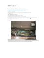
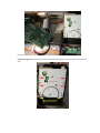
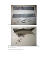
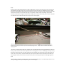
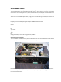
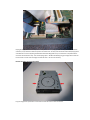
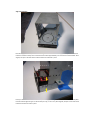
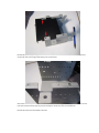
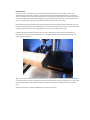
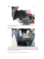
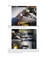
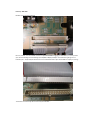
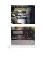
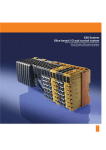
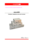
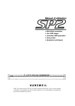
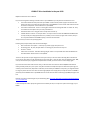
K2000 CF Drive installation in the year 2012 Maybe this will be of use to someone. If you are thinking about installing a SCSI hard drive in your K2000 then you may want to consider these cons: A hard drive will draw more power from your K2000 ‐ it will cause the power supply to work harder and make more heat. A hard drive also generates heat, so the K2000 will run even hotter. Heat reduces the life of electrical components. You will need a fan in your K2000. A hard drive is mechanical ‐ There are moving parts and there are bearings that wear in normal use. They are sensitive to shock (from a drop or a fall) and vibrations. Hard drives make noise ‐ they get noisier as they wear and heat up. Limited selection of drives ‐ it's the year 2012....see if you can find a brand new 2GB Wide SCSI HDD that is on the (now 15 year old) approved drive list ‐ probably not. You could try a lager drive of course, but you can only access 2GB from the K2000 anyway, so the rest will be wasted. The pro is that you can still use your floppy drive. Installing a CF (Compact Flash) drive has these advantages: Does not draw as much power ‐ no disk spin‐up power supply droop. Runs cool. No moving parts ‐ Ok, well, the eject button is a moving part, but that's the only one. No noise ‐ silence! Fewer limits in selection ‐ IDE makes hacking old gear easier in this post‐SCSI world. StarTech & Addonics both have IDE CF readers new for around $30US. The con is that you will lose your floppy drive unless you mount your CF card reader internally (which should work too, as the CF drive without a 3.25" bay will take up much less space ‐ I will not cover internal installation here). IMO, once you see how fast your programs and samples load from SCSI, you'll never want to use the floppy again. If you have done the same research that I have, you will have seen much mention of the SCM/Microtech SCSI CF drives (pcd‐47B, pcd‐50, etc.) as an option. They were a viable and inexpensive option as little as five years ago, but now they can be hard to find, expensive and still may not work with your K2000. In many cases, you might be limited to using only certain CF cards. The drives are also longer/deeper than a floppy drive, so they will not fit in a K2000R. I personally tried a SCM PCD‐47b in my K2000S v3 and it would not write without rebooting my K2000S, though it read fine. However, this person seemed to get his pcd‐47b working well: http://www.keyboardz.net/en/kurzweil-k2000-adding-ascsi-card-reader.html I have read reports of other people using this drive successfully as well, so it may be an option worth trying on your K2000. You may have also seen USB floppy drives emulators where a USB device replaces the floppy and multiple floppy disk images can be placed on a thumb drive. I have also tried this, unsuccessfully (on a K2500RS). Again, there are other folks who got this working. The problem with this is that you are limited to loading 1.44M at a time (not so good for large samples), and you may need to use specific USB sticks. Ebay photo by cmykanalog I believe the best option for anyone still using a K2000 is to use an IDE/SCSI bridge to adapt the SCSI bus to an IDE drive. I might add that there are other card readers out there and there are other bridges available that may work with the K2000 as well. Perhaps a SCSI/SATA bridge will work with a SSD drive or SD card reader ‐ my point is that there may be other ways to do this, with more possibilities. This setup is working for me with no problems (in a K2000R OS3.87J and this keyboard, a K2000vps OS3.54J) ‐ so I'd like to share my mods with you :‐) K2000x Keyboard Parts needed: Acard AEC‐7720U ~ $50 ‐ $270US used ‐ on eBay as of 13 June 2012 ALT ‐ Acard AEC‐7720UW ~ $50 ‐ $270US used ‐ on eBay as of 13 June 2012 ALT – 68pin to 50pin SCSI adapter w/High Byte Termination ~ $18US CF reader, 3.5" bay ~ $30US 2GB Compact Flash ~ $10US You can use larger cards, but the K2000 will only format 2GB 13" SCSI cable ~ $? 3" IDE cable, 40p male to female ~ $? FDD Y power cable (Molex to 2 Berg connectors) ~ $6US 10" HDD power cable extender, male to female ~ $? If fan is installed Kurzweil K2000 OS 3.54 and up (3.87 is recommended – I have confirmed that this will not work with OS 3.01) Double sided tape, Velcro or hot glue ~ $? Open your K2000. Find a good workspace – the dining room table works for me! Lay a towel under your keyboard and support the wheel side with a book or small box. This is to keep pressure off of the wheels assembly and stanchions. Unscrew the 7 bottom cover bolts. Remove the bottom cover carefully, minding the fan cable (if installed). Disconnect fan cable harness at J18 A fan kit is recommended if you do not already have one installed. Remove SMP‐K option if you have one. Remove 3 bolts in the rear and two screws on the top. No need to unplug the SMP‐K cables; just move the card out of the way to get to the FDD cables. Remove the floppy drive. Unscrew the two bolts on the bottom (black plate) and then four bolts on the sides of the drive. Leave the mounting brackets in place. Fold the floppy cable as pictured to easily slide it under the mounting bracket. You can reinstall the SMP‐K now that the floppy cables are out from under it. Install CF drive. Note that there are only two screws; one on either side. Look at how much room we have to work with! Set SCSI/IDE bridge ID. This one is set to SCSI 0. Do not use SCSI 6 as that is the K2000 processor’s ID I used an AEC‐7720UW and a 68 to 50 pin adapter with high byte termination. The AEC‐7720U does not need an adapter. Cut and terminate cables The reason we need a short male to female IDE cable is because the SCSI/IDE card would not clear the bracket if installed directly on the drive. I used old cables from previous projects & bought connectors from the local electronics shop. Cables are now cut and terminated. Note the IDE cable has one male end. The connector in the middle of the SCSI cable is not necessary – this was just a leftover from my other CF install. The white Molex connectors will be used to make a power cable extension. You might find it easier to have these cables made for you. CF ‐ IDE ‐ Bridge – Adapter connection Attach the IDE cable between the drive and bridge. The good thing about using the adapter is that it provides a large enough surface to secure the assembly to the drive bay/top cover. I used hot glue for this, but you can also use double sided tape or Velcro. Leave enough room between the adapter and rear cover to insert/remove the SCSI cable. Adapter ‐ SCSI connection Connect the SCSI cable to the bridge assembly and then to the mainboard. You should also connect the FDD power Y cable to the drive and bridge at this time. Try to fold the SCSI cable so that it does not block the flow of air from the fan duct (located under the drive when the bottom cover is installed). Power Install the power cable extender between Y cable and HDD power connector on the fan harness. Mine is made from some leftover small gauge speaker wire. Insert the cable harness back into J18. If your K2000 did not have a fan kit, then you will need to make a cable that goes from J18 to the drive bay. I recommend using the old floppy power cable as the board connector is the same for J18 – only +5v is needed for the CF reader and the bridge. Clip the FDD connector, add wire to the length and terminate with a HDD power connector. Alternately, you can cut the receptacle and +12V wire off of an HDD extender cable and join the two cables together. At this point, before you apply power to your K2000, you’ll first want to check that you made your connections correctly, that nothing is shorted or open and that everything is secure – always check and double check before applying power! You can also re‐install the black plate from the floppy drive. This black plate fills the slight gap between the bottom of the bay and the drive. Reinstall the black plate as it was on the floppy drive – there is a little ridge on the bay opening that acts as a stop for the plate. The plate will stick out a few millimeters from the front of the drive. Since there are no bolt holes in the CF drive, use double sided tape to secure it to the bottom of the CF drive where the bolts were. Sorry, I forgot to take a picture of this, but you can see the plate on the floppy drive picture at the beginning of the guide. You may now put the bottom cover back on the synth (do not put the bolts back in until after testing). Make sure you aren’t pinching any cables. Flip the keyboard so you can see the display. Test – Format Boot your K2000. Press the ‘DISK’ button. Now, there will likely be a pause of 6 to 10 seconds before the disk mode page shows up on the display. *See note below. Select your drive using the alpha wheel. Mine is set to SCSI 0. I used a Silicon Systems 4GB card, and it showed up on the display. Press the ‘MORE’ soft button until you see ‘FORMAT’ – press ‘FORMAT’. The menu will ask (repeatedly) if you are sure you want to format, press ‘OK’ until it starts to format. The K2000 will only format 2GB. Now that we know everything is working, unplug the line cord and finish reassembling the synth by putting the 7 bottom cover bolts back in. You should have 4 small bolts left over from the floppy drive ‐ do what you want with them. Done! Here’s the finished installation in my K2000vps K2000R Rack Module This CF installation on the K2000R (and K2500R) is the only CF configuration that will work in K2xR, as far as I know. This is because the SCM CF drives are too deep to fit in the rack units – there is not enough room in the rack; the back of the drive will touch the audio/power board, and the front will stick out from the faceplate. Because this IDE CF card reader is so short, it can be installed in a number of ways. I will show an easy, accurate way to do this. *If you have not read the K2000 keyboard section, I urge you to read it before starting as there may be information or steps not covered in this section. Parts needed: Everything listed in the K2000 keyboard guide except for the HDD power cable extender #4 sheet metal screws Zip ties Tools needed: Drill 1/8” drill bit 3/32” drill bit Tape File Safety glasses *Always use these when using power tools, ALWAYS! Start by opening up your rack unit. This a “Frankenstein” rack that I built out of parts from dead racks, so this may not look exactly like yours. As with the K2000 keyboard, lay a towel under the rack so that it does not scratch your working surface. Remove the tape holding the display and button board ribbon cables onto the side of the drive bracket. Remove the four screws holding the bracket to the chassis (this will be self‐explanatory once you start working). Do not remove the bracket and floppy drive yet. Unplug the floppy ribbon cable and power cable. If you have the sampling option installed, you should not need to remove it, but you will have a little less space to work with here. You may now remove the drive bracket, floppy drive and cables all at one once by tilting the bracket forward and lifting back and up out of the rack unit. (Note that the connector marked ‘Audio In Exp.’ Is for the sampling option – DO NOT accidentally plug your floppy ribbon cable into this connector or it will short the floppy and melt the cable – ask me how I know ) Remove the floppy drive from the bracket. Lay your floppy drive upside down on the table and note the location of the screw holes. Align and mark holes Place the floppy bracket on top of the drive and align the bracket holes with the floppy holes. Pay attention that the bracket is oriented correctly. The front of the drive should be approximately 1 ½” from the front of the bracket. Once aligned, use tape on the sides of the bracket and drive to hold them in place. Insert your CF reader into the bracket and on top of the floppy drive. Align the front side bolt holes so that they have the same vertical alignment (you can do this with your eye, or use a ruler). Once aligned, use tape on the inside of the bracket and CF drive to hold it in place. Remove the tape holding the floppy drive to the bracket. Flip the bracket and CF drive upside down. Use a pencil to mark the CF drive holes using the two existing holes in the bracket. Also make a mark two spots on the drive bracket about ¾” – 1” from the original rear floppy drive holes. The new rear holes don’t need to be exact; they are just there to keep the new CF drive more securely fastened. Remove the CF drive from the bracket at this time. Drilling the holes Use a punch to put an indentation on the marks that you made the bracket. If you do not have a punch, use a sheetrock screw and a hammer. This step is important because, without these little indentations, your drill bit will “dance” or wander around on the metal and start a hole in the wrong place, especially when using a hand power drill. The indentation gives the drill bit something to grab onto. Now drill your holes using a 1/8” drill bit to make the two new rear mounting holes. Use a file or larger drill bit to deburr the new holes when finished. Re‐inset the CF drive into the bracket, aligning the two front holes that you marked previously. Now mark your new rear holes on the CF drive just as you did with the front. You should now have four pencil marks on your CF drive that exactly correspond to the holes in the floppy bracket. Sorry, I didn’t take a picture of this step. Carefully remove the CF reader internals from the 3.5” drive chassis and set aside. You need to remove the CF board/slot mechanism from the 3.5” chassis so as not to damage it while drilling. Be careful not to smudge your pencil marks while doing this. Again, use a punch to make indentations in the center of your pencil marks. I recommend using a piece of soft wood underneath so as not to scratch or bend the front of the drive chassis while punching and drilling. You can now drill all four holes with a 3/32” drill bit. When finished, use the 1/8” bit from the previous steps to deburr the new drive holes. The CF card internals can now be reinstalled back into the 3.5” drive chassis. Mount the CF reader to the floppy bracket. Now you can permanently install the CF drive into the floppy bracket using #4 sheet metal screws. Looks good! The hard work is done. Mount the SCSI/IDE There is plenty of space in the bracket for the IDE cable, SCSI/IDE adapter, and 68pin to 50pin SCSI adapter. As with the K2000 keyboard, I used hot glue to affix the adapter to the floppy bracket – this pretty much holds everything in place and makes for easier serviceability. I recommend that you use an adhesive that you can trust – if the assembly falls, the SCSI/IDE could short if it touches the chassis or bracket. For extra insurance, you could line the surrounding area with tape to prevent problems if it does fall. You can connect the FDD Y power cable to the drive and SCSI/IDE adapter now. Power cable The K2000R (and K2500R) come with a HDD cable that is long enough to reach the floppy bay. Clip the zip ties off of the power cable harness and run the Molex connector to the floppy bay. Connect the HDD power cable to the FDD Y power cable. Re‐tie the power cable harness, minus the HDD cable. I routed the HDD cable (also connects to fan) along part of the button board cable and wrapped a bit of gaffers tape around it so that it would be anchored. The rest of the cable and attached fan start circuit were routed under the PRAM expansion connector. You can route the cable any way you like, as long as it will not rub against any electrical points. Also, try to avoid getting the wire too close to the heatsink. Consider if your rack will be stationary or moved around a lot, and secure your wires/cables accordingly. Last step – SCSI cable DO NOT connect the SCSI cable yet! Here’s a problem – the internal SCSI connector is keyed BACKWARDS! Plugging your SCSI cable in, as is, will prevent your rack from booting and could damage your SCSI/IDE or 68/50 pin adapter. This seems like a glaring error on Kurzweil’s part – maybe they wanted the user to use a backwards cable as part of their HDD kit. Anyway, it’s wrong! The solution is to file the key off of one end of your SCSI cable….. …and then plug the cable in backwards so that the red stripe (pin 1) of the cable is closest to the right side of the unit. Finishing up At this point, before you apply power to your K2000R, you’ll first want to check that you made your connections correctly, that nothing is shorted or open and that everything is secure – always check and double check before applying power! Follow the instructions in the last part of the K2000 Keyboard section; Test – Format to get your drive set up. Once you are sure everything is working as it should, you may close up the K2000R. You should have 4 small bolts left over from the floppy drive ‐ do what you want with them. It’s up to you to decide if you want to invest $100US or more in your old synth. For me, it was worth the money and effort to be able to load samples and programs quickly with a boot macro. All I need to do is turn on my synth and it loads everything automatically – essential in a live situation. I spent a little over $100US each to modify my two K2000S’s. It would have been less expensive to use a PCD drive (especially if it had worked for me), but much I preferred the clean look of a black, single slot CF drive in my K2000, and was willing to pay a little more for it. This modification should work on the K2500/K2500R as well. *Note regarding DISK Mode pause. I was alerted to issues of a 7 second pause when using the AEC‐7720. I too experienced this pause when I first completed this mod on the other K2000, but it never happened again. To find out why, I loaded 4 different cards with the same files on each. Here is what I learned after a couple of hours of testing: Yes, this setup will apparently work (meaning the synth will boot and play) with any CF card (I used 2 GB Transcend 80x & 133x, SiliconSystems 4GB, and a Smartdisk 512MB from an old camera), but all will have a seven second (or more) delay when accessing DISK Mode. I do not feel that this is a problem, but some folks may be annoyed by the delay. This pause happens only the first time you press ‘DISK’ after powering up, so subsequent presses should bring the menu up as quickly as other menus. …but, if you use of the macro function, you can make a boot macro (BOOT.MAC), which seems to solve the 7 second pause when accessing DISK mode. This is why I did not notice the delay – I use a boot macro to load samples from the CF card during boot up. As soon as the K2000 is booted, DISK Mode works as you would expect (I suspect that the 7 second delay happens during startup – it makes the delay transparent). So, to avoid the delay when you press DISK, use the macro function to make a BOOT.MAC file and enable Startup: and Library: with your SCSI ID. You can find out how to do this in the manual. ***Disclaimer*** This guide has been written and posted to show and describe a technical procedure that has worked for me on my keyboards; it may work for you or it may not. You may try this procedure, but try at your own risk. To those less technically inclined, some of the steps in this document may appear difficult or missing some details – I would recommend that this procedure be performed by a competent electronics tech as there are potentially lethal voltages/currents inside. I am an experienced tech who is not associated with Kurzweil Music Systems, Acard, Addonics, StarTech or any other brands (whose names and trademarks remain the sole property of their respective owners) mentioned in this document. I am also from a part of the world where people often take no responsibility for their actions, hence this disclaimer: I will not be held responsible for any damage, injury or death to persons or property caused by following the steps in this document. If you have chosen to follow the steps in this guide, it is understood that you do so at your own risk. Woodman1200 June 2012 K2000R addendum added October 2012