1
User’s Manual.
_____--.---
EPSON”
.
Y465ss127mo
EPSON®
LQ-2550
User’s Manual
FCC COMPLIANCE STATEMENT
FOR AMERICAN USERS
This equipment generates and uses radio frequency energy and if not installed and used properly, that
is, in strict accordance with the manufacturer’s instructions, may cause interference to radio and
television reception. It has been type tested and found to comply with the limits for a Class B
computing device in accordance with the specifications in Subpart J of part 15 of FCC Rules, which are
designed to provide reasonable protection against such interference in a residential installation.
However, there is no guarantee that interference will not occur in a particular installation. If this
equipment does cause interference to radio or television reception, which can be determined by turning
the equipment off and on, the user is encouraged to try to correct the interference by one or more of the
following measures:
- Reorient the receiving antenna
- Relocate the printer with respect to the receiver
- Plug the printer into a different outlet so that the printer and receiver are on different branch
circuits.
If necessary, the user should consult the dealer or an experienced radio/television technician for
additional suggestions. The user may find the following booklet prepared by the Federal
Communications Commission helpful:
“Television Interference Handbook.”
This booklet is available from the U.S. Government Printing Office, Washington, DC 20402. Stock No.
004~00&00450-7.
WARNING
The connection of a non-shielded printer interface cable to this printer will invalidate the FCC
Certification of this device and may cause interference levels which exceed the limits established by the
FCC for this equipment. If this equipment has more than one interface connector, do not leave cables
connected to unused interfaces.
IMPORTANT NOTICE
Seiko Epson Corporation and its affiliates (“Epson”) specifically disclaims all liability for problems and
all damages which may result from the combination or use of Epson printers with software, hardware
product options, such as interface boards, or other items not supplied by Epson or otherwise designated
by Epson to be compatible with Epson printers. Epson further specifically disclaims all liability for
problems and all damages which may result from the unauthorized alteration or modification of Epson
printers, whether or not such alteration or modification is accomplished by software, hardware or other
means.
All rights reserved. No part of this publication may be reproduced, stored in a retrieval system, or
transmitted, in any form or by any means, mechanical, photocopying, recording or otherwise, without
the prior written permission of Seiko Epson Corporation. No patent liability is assumed with respect to
the use of the information contained herein. While every precaution has been taken in the preparation
of this book, Seiko Epson Corporation assumes no responsibility for errors or omissions. Neither is any
liability assumed for damages resulting from the use of the information contained herein.
Epson America, Inc. shall not be liable against any damages or problems arising from the use of
any options or any consumable products other than those designated as Original Epson Products or
Epson Approved Products by Seiko Epson Corporation.
Epson is a registered trademark of Seiko Epson Corporation.
IBM is a registered trademark of International Business Machines Corporation
Microsoft is a registered trademark of Microsoft Corporation.
Copyright © 1988 by Seiko Epson Corporation
Nagano, Japan
ii
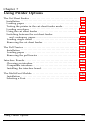
Table of Contents
Introduction . . . . . . . . . . . . . . . . . . . . . . . . . . . . . . . . . . . . . .
Features . . . . . . . . . . . . . . . . . . . . . . . . . . . . . . . . . . . . . . . . . .
Options . . . . . . . . . . . . . . . . . . . . . . . . . . . . . . . . . . . . . . . . . .
About This Guide . . . . . . . . . . . . . . . . . . . . . . . . . . . . . . . . . .
Where to Get Help . . . . . . . . . . . . . . . . . . . . . . . . . . . . . . . . .
1-1
Setting Up the Printer . . . . . . . . . . . . . . . . . . . . . . . . . . . . . . .
Unpacking the Printer . . . . . . . . . . . . . . . . . . . . . . . . . . . . . .
Choosing a Place for the Printer . . . . . . . . . . . . . . . . . . . . . .
Assembling the Printer . . . . . . . . . . . . . . . . . . . . . . . . . . . . . .
Testing the Printer . . . . . . . . . . . . . . . . . . . . . . . . . . . . . . . . . .
Connecting the Printer to Your Computer . . . . . . . . . . . . . .
Setting Up Your Application Software . . . . . . . . . . . . . . . . .
l-2
l-6
l-7
1-15
l-22
1-27
2
Paper Handling . . . . . . . . . . . . . . . . . . . . . . . . . . . . . . . . . . . .
Using Single Sheets . . . . . . . . . . . . . . . . . . . . . . . . . . . . . . . . .
Using Continuous Paper . . . . . . . . . . . . . . . . . . . . . . . . . . . .
Switching between Continuous and Single Sheets . . . . . . . .
Printing on Special Paper . . . . . . . . . . . . . . . . . . . . . . . . . . .
2-1
2-2
2-5
2-16
2-22
3
Using the Printer . . . . . . . . . . . . . . . . . . . . . . . . . . . . . . . . . . .
Operating the Control Panel . . . . . . . . . . . . . . . . . . . . . . . . .
SelecType Settings . . . . . . . . . . . . . . . . . . . . . . . . . . . . . . . . .
Page Length . . . . . . . . . . . . . . . . . . . . . . . . . . . . . . . . . . . . . . .
Skip Over Perforation . . . . . . . . . . . . . . . . . . . . . . . . . . . . . .
Setting the Loading Position . . . . . . . . . . . . . . . . . . . . . . . . .
Short Tear-Off . . . . . . . . . . . . . . . . . . . . . . . . . . . . . . . . . . . . .
Selecting Typestyles . . . . . . . . . . . . . . . . . . . . . . . . . . . . . . . .
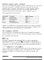
Choosing an International Character Set . . . . . . . . . . . . . . .
Choosing a Character Table . . . . . . . . . . . . . . . . . . . . . . . . .
3-1
3-2
3-8
3-26
3-28
3-30
3-31
3-33
3-39
3-40
1
Using Software and Graphics . . . . . . . . . . . . . . . . . . . . . .
Using the LQ-2550 with Application Programs . . . . . . . .
Computer-Printer Communication . . . . . . . . . . . . . . . . . .
Enhancing Your Printing . . . . . . . . . . . . . . . . . . . . . . . . . . .
Graphics
..............................
User-Defined Characters . . . . . . . . . . . . . . . . . . . . . . . . . . .
4-1
4-2
4-5
4-7
4-12
4-23
Maintenance and Transportation . . . . . . . . . . . . . . . . . . .
Cleaning the Printer . . . . . . . . . . . . . . . . . . . . . . . . . . . . . . .
Replacing the Ribbon . . . . . . . . . . . . . . . . . . . . . . . . . . . . . .
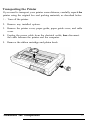
Transporting the Printer. . . . . . . . . . . . . . . . . . . . . . . . . . . .
5-1
5-2
5-3
5-7
Troubleshooting . . . . . . . . . . . . . . . . . . . . . . . . . . . . . . . . . .
Problems and Solutions . . . . . . . . . . . . . . . . . . . . . . . . . . . .
Data Dump Mode . . . . . . . . . . . . . . . . . . . . . . . . . . . . . . . . .
6-1
6-2
6-6
Using Printer Options . . . . . . . . . . . . . . . . . . . . . . . . . . . . .
The Cut Sheet Feeder . . . . . . . . . . . . . . . . . . . . . . . . . . . . . .
The Pull Tractor . . . . . . . . . . . . . . . . . . . . . . . . . . . . . . . . . . .
Interface Boards . . . . . . . . . . . . . . . . . . . . . . . . . . . . . . . . . . .
The Multi-Font Module . . . . . . . . . . . . . . . . . . . . . . . . . . . .
7-1
7-2
7-21
7-33
7-45
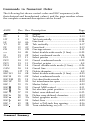
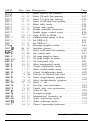
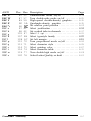
Command Summary . . . . . . . . . . . . . . . . . . . . . . . . . . . . . .
Commands in Numerical Order . . . . . . . . . . . . . . . . . . . . .
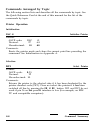
Commands Arranged by Topic. . . . . . . . . . . . . . . . . . . . . .
8-1
8-5
8-8
Appendix A . . . . . . . . . . . . . . . . . . . . . . . . . . . . . . . . . . . . . .
Printer Specifications . . . . . . . . . . . . . . . . . . . . . . . . . . . . . .
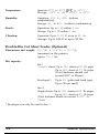
Double-Bin Cut Sheet Feeder Specifications. . . . . . . . . . .
Interface Specifications . . . . . . . . . . . . . . . . . . . . . . . . . . . . .
Initialization . . . . . . . . . . . . . . . . . . . . . . . . . . . . . . . . . . . . . .
Default Settings . . . . . . . . . . . . . . . . . . . . . . . . . . . . . . . . . . .
A-l
A-2
A-6
A-9
A-13
A-14
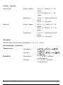
Appendix B . . . . . . . . . . . . . . . . . . . . . . . . . . . . . . . . . . . . . .
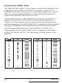
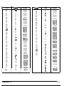
Proportional Width Table . . . . . . . . . . . . . . . . . . . . . . . . . .
Character Tables . . . . . . . . . . . . . . . . . . . . . . . . . . . . . . . . . .
B-1
B-2
B-6
Glossary . . . . . . . . . . . . . . . . . . . . . . . . . . . . . . . . . . . . . . . . .
GL-1
Index . . . . . . . . . . . . . . . . . . . . . . . . . . . . . . . . . . . . . . . . . . . . Index-l
iv
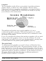
Introduction
The LQ-2550 is the latest in the Epson@ line of advanced 24-pin impact
dot matrix printers, combining high performance and reliability with a
wide range of features.
Features
In addition to the high-quality printing and ease of operation you have
come to expect from Epson printers, the LQ-2550 offers the following:
An improved control panel design that allows direct selection of all
of the printer’s main features, such as character font and pitch as well
as normal or condensed printing.
An advanced paper handling system that allows you to easily switch
between single sheets and continuous paper by pressing the
appropriate panel buttons. The LQ-2550 automatically detects the
thickness of the paper you load, so optimum printing results can be
easily achieved with various types of paper. You can use single sheets
without removing the continuous paper, or you can use continuous
paper even while the optional Cut Sheet Feeder is installed.
A tear-off feature that saves paper. After you tear off the latest sheet
printed on continuous paper, the printer feeds the paper back to the
loading position so that you can use all of the next sheet.
Multi-part forms that consist of up to six parts (5 copies plus the
original) can be printed. You can also print on labels and envelopes.
A micro-adjustment feature that allows you to feed the paper
forward or backward in 1/180th of an inch increments to finely
adjust the top of form, loading, and short tear-off positions.
The following seven built-in Letter Quality fonts are provided for
producing high-quality documents:
Roman, Sans Serif, Courier, Prestige,
Script, OCR-A, OCR-B
Introduction
1
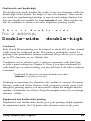
Two additional Letter Quality fonts are available with the
optional Multi-Font Module: ORATOR and ORATOR-S
Draft mode with fast printing of up to 333 characters per second
in 10 cpi (characters per inch), and 400 characters per second in
12 cpi.
Color printing in seven colors with a color ribbon (included).
With suitable graphics software, you can mix colors within a line
or even print screen dumps in color.
Compatibility with the Epson ESC/P commands used by the
LQ-1500, LQ-800, LQ-1000, LQ-2500, LQ-850, LQ-1050 and LQ500 printers.
Options
A variety of printer options is available for use with your LQ-2550
printer. For detailed information on the installation and use of these
options, see Chapter 7.
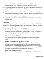
Double-Bin Cut Sheet Feeder (#7343)
The cut sheet feeder gives you easier and more efficient
handling of single sheet paper or envelopes. Up to 150 sheets of
standard bond paper in each of the two bins can be
automatically fed into the printer without reloading.
Pull Tractor Unit (#7314)
This option improves the performance of continuous paper
handling. It is especially useful with continuous multi-part
forms.
Ribbon Cartridges (#7762, #7763, #7764)
There are two types of ribbon cartridges in addition to the
standard black ribbon cartridge (#7762). Included with your
printer are the standard black ribbon cartridge (#7762) and the
color ribbon cartridge (#7763). The film ribbon cartridge (#7764)
provides you with even higher-quality printing.
Multi-Font Module (#7407)
This adds two Letter Quality fonts ORATOR and ORATOR-S.
2
Introduction
LQ Printer Software (DCB-LQ2)
This package features a driver and high-resolution fonts for use
with Microsoft@ Windows Presentation Manager version 2.0 and
Windows/386 Presentation Manager. It lets you use your Epson
LQ printer to print pages created under the Microsoft Windows
operating environment.
Optional Interface Boards
A number of optional interface boards can be used to supplement the
LQ-2550’s built-in parallel and serial interfaces. Guidelines for
choosing the right interface and instructions on installing the boards
are given in Chapter 7.
About This Guide
This user’s guide provides fully illustrated, step-by-step instructions for
setting up and operating the LQ-2550 printer.
l
l
l
l
l
l
Chapter 1 contains information on unpacking, setting up, testing,
and connecting the printer, so be sure to read and follow the
instructions in this chapter first.
Chapters 2 and 3 include important information on paper handling
and general printer operation. This information is necessary for the
day-to-day operation of your printer.
Chapter 4 contains information designed to help you get the most
from your printer. This section includes advice on the use of
software, commands, graphics, and user-defined characters. Also,
see Chapter 8 for a summary of printer commands.
If the printer does not operate properly or the printed results are not
what you expect, see Chapter 6 for a list of recommended solutions.
Other chapters and appendixes contain information on general
maintenance, use of the printer options, and specifications. You will
also find a glossary of printer terms and an index.
At the back of this guide is a Quick Reference card with the
information you are likely to need most often.
Introduction
3
Conventions used in this guide
WARNlNG: must be followed carefully to avoid damage to
your printer and computer.
Cautions: should be followed carefully to ensure that your printer
operates correctly.
Notes: contain important information and useful tips on the operation
of your printer.
Where to Get Help
Customer support and service for Epson products are provided by a
network of authorized Epson Dealers and Customer Care Centers
throughout the United States. Epson America provides product
information and support to its dealers and Customer Care Centers.
Therefore, we ask that you contact the business where you
purchased your Epson product to request assistance.If the people
there do not have the answer to your question, they can obtain it
through our dealer support program.
Epson is confident that this policy will provide you with the
assistance you need.
Call the Epson Consumer Information Center at l-800-922-8911 for
the following:
l
l
l
The location of the nearest Epson dealer
The location of the nearest Customer Care Center
Information on Epson User Groups.
To locate or purchase accessories or supplies, contact your nearest
Epson dealer or call l-800-873-7766.
4
Introduction
Chapter 1
Setting Up the Printer
Unpacking the Printer . . . . . . . . . . . . . . . . . . . . . . . . . . . . . . . . . . . . . . . 1-2
Removing the protective materials . . . . . . . . . . . . . . . . . . . . . . . . . . . 1-2
Choosing a Place for the Printer . . . . . . . . . . . . . .
1-6
Assembling the Printer . . . . . . . . . . . . . . . . . . . . . . . . . . . . . . . . . . . . . . . 1-7
Installing the platen knob . . . . . . . . . . . . . . . . . . . . . . . . . . . . . . . . . . 1-7
Installing the ribbon cartridge . . . . . . . . . . . . . . . . . . . . . . . . . . . . . . . 1-9
Attaching the paper guide . . . . . . . . . . . . . . . . . . . . . . . . . . . . . . . . . 1-12
Testing the Printer . . . . . . . . . . . . . . . . . . . . . . . . . . . . . . . . . . . . . . . . . . 1-15
Connecting to a power supply . . . . . . . . . . . . . . . . . . . . . . . . . . . . . 1-15
Running the self test . . . . . . . . . . . . . . . . . . . . . . . . . . . . . . . . . . . . . . 1-16
Connecting the Printer to Your Computer . . . . . . . . . . . . . . . . . . . . . . 1-22
The parallel interface . . . . . . . . . . . . . . . . . . . . . . . . . . . . . . . . . . . . . l-22
The serial interface . . . . . . . . . . . . . . . . . . . . . . . . . . . . . . . . . . . . . . . 1-24
Setting Up Your Application Software . . . . . . . . . . . . . . . . . . . . . . . . . 1-27
Choosing from a menu . . . . . . . . . . . . . . . . . . . . . . . . . . . . . . . . . . . 1-28
Setting Up the Printer
1-1
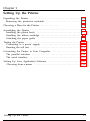
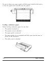
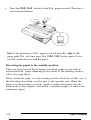
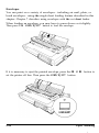
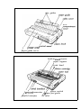
Unpacking the Printer
As you unpack the printer, check that you have all parts shown below
and that none have been damaged during transportation.
Cabfe cover
Color
ribbon
Paper guide
cartridge
Ribbon cartridge
Cross-head screw driver
Power cable
Platen knob
5Y
Optional connector lock nuts
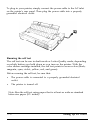
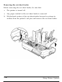
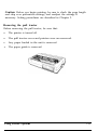
Removing the protective materials
The printer is protected during shipping by two screws, a print head
protector, and white foam packing material. These protective items must
be removed before you turn on the printer by following the steps below.
After removing these items, store them with the other packaging material
in case you ever need to transport your printer.
1-2
Setting Up the Printer
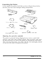
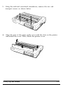
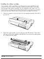
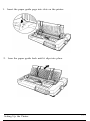
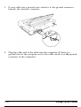
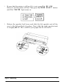
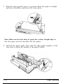
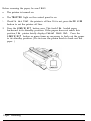
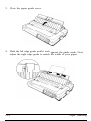
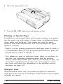
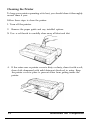
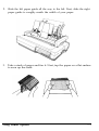
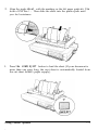
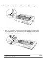
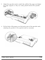
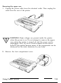
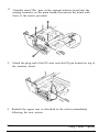
1. Open the printer cover and raise it to an upright position; then lift it
up and off.
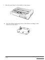
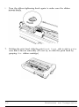
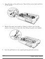
2. Open the paper guide cover as shown in the illustration. Then raise
the cover slightly and lift the cover away from the printer at a slight
upward angle.
Setting Up the Printer
1-3
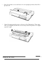
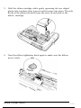
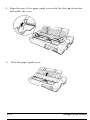
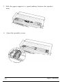
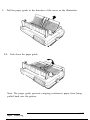
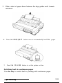
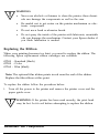
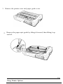
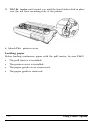
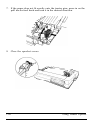
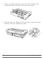
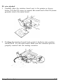
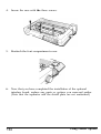
3. Remove the print head protector and white foam packing
material.
4. Slide the print head all the way to the middle
Setting Up the Printer
1-4
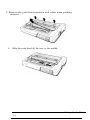
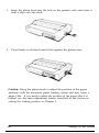
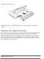
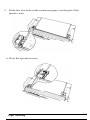
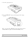
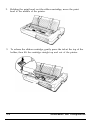
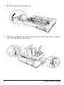
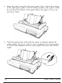
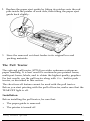
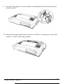
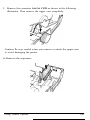
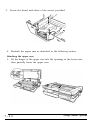
5. Using the enclosed cross-head screwdriver, remove the two red
transport screws as shown below.
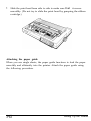
6. Align the pins of the paper guide cover with the slots on the printer
and attach the cover. Next, attach the printer cover.
Setting Up the Printer
1-5
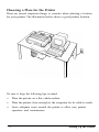
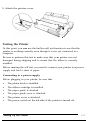
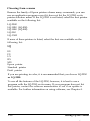
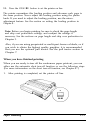
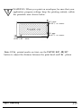
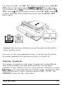
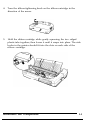
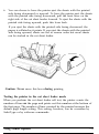
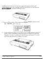
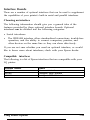
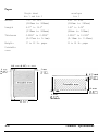
Choosing a Place for the Printer
There are several important things to consider when selecting a location
for your printer. The illustration below shows a good printer location.
Be sure to keep the following tips in mind:
l
Place the printer on a flat, stable surface.
l
Place the printer close enough to the computer for its cable to reach.
l
1-6
Leave adequate room around the printer to allow easy printer
operation and maintenance.
Setting Up the Printer
Use a grounded outlet - one that has three holes to match the
power plug on the printer. Don’t use an adapter plug.
Avoid locations that are subject to direct sunlight, excessive heat,
moisture, or dust.
Avoid using electrical outlets that are controlled by wall switches or
automatic timers. Accidental disruption of power can wipe out
information in your computer’s and printer’s memory.
Avoid using outlets on the same circuit with large motors or other
appliances that might disturb the power supply.
Keep the entire computer system away from potential sources of
interference, such as loudspeakers or the base units of cordless
telephones.
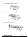
Assembling the Printer
After you have decided on a location for your printer, it is necessary to
install the platen knob, the ribbon cartridge, and the paper guide.
Installation instructions for these three components are given below.
Installing the platen knob
After you have decided on a location for your printer, the first step in
setting it up is to install the platen knob.
You will find the platen knob packed in an indentation in the white foam
packing material.
Setting Up the Printer
1-7
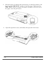
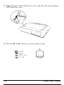
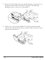
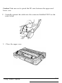
1. Insert the platen knob into the hole on the printer’s side and rotate it
until it slips onto the shaft.
2. Press firmly on the knob until it fits against the printer case.
Caution: Using the platen knob to adjust the position of the paper
interferes with the automatic paper loading system and may cause a
paper jam. If you need to adjust the position of the paper after it is
loaded, use the micro-adjustment feature described in the section on
setting the loading position in Chapter 3.
1-8
Setting Up the Printer
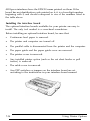
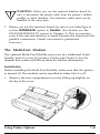
Installing the ribbon cartridge
Your printer’s ribbon cartridges are designed for easy installation and
removal. The color ribbon cartridge, standard black ribbon cartridge,
and optional film ribbon cartridge are all installed in the same way. (A
color ribbon cartridge and standard black ribbon cartridge are included
with your printer.) Install any of these ribbon cartridges as follows:
1. Open the printer cover and raise it to an upright position; then lift it
up and off.
2. Open the paper guide cover as shown in the illustration. Then raise
the rear of the cover slightly and lift the cover away from the printer
at a slight upward angle.
Setting Up the Printer
1-9
3. Slide the print head to the middle of the printer.
4. Turn the ribbon-tightening knob on the ribbon cartridge in the
direction of the arrow.
1-10
Setting Up the Printer
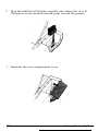
5. Hold the ribbon cartridge while gently squeezing the two ridged
plastic tabs together; then lower it until it snaps into place. The side
hooks in the printer should fit into the slots on each side of the
ribbon cartridge.
6. Turn the ribbon tightening knob again to make sure the ribbon
moves freely.
Setting Up the Printer
1-11
7.
Slide the print head from side to side to make sure that it moves
smoothly. (Do not try to slide the print head by grasping the ribbon
cartridge.)
Attaching the paper guide
When you use single sheets, the paper guide functions to feed the paper
smoothly and efficiently into the printer. Attach the paper guide using
the following procedure.
Setting Up the Printer
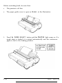
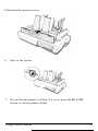
1. Insert the paper guide pegs into slots on the printer.
2. Lean the paper guide back until it slips into place.
Setting Up the Printer
1-13
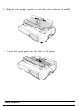
3. Align the pins of the paper guide cover with the slots on the printer
and attach the cover.
4. Close the paper guide cover.
1-14
Setting Up the Printer
5. Attach the printer cover.
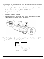
Testing the Printer
At this point, you can use the built-in self test function to see that the
printer is working correctly even though it is not yet connected to a
computer.
Be sure to perform this test to make sure that your printer was not
damaged during shipping and to ensure that the ribbon is correctly
installed.
Before running the self test, you need to connect your printer to a power
supply and load a sheet of paper.
Connecting to a power supply
Before plugging in your printer, be sure that:
l
The platen knob is installed.
l
The ribbon cartridge is installed.
l
The paper guide is attached.
l
The paper guide cover is attached.
l
The printer cover is attached.
l
The power switch on the left side of the printer is turned off.
Setting Up the Printer
1-15
To plug in your printer, simply connect the power cable to the AC inlet
on the printer’s rear panel. Then plug the power cable into a properly
grounded electrical outlet.
Running the self test
The self test can be run in draft mode or Letter Quality mode, depending
on which button you hold down as you turn on the printer. With the
color ribbon cartridge installed, the self test prints in seven colors (black,
magenta, cyan, violet, yellow, red, and green).
Before running the self test, be sure that:
l
l
The power cable is connected to a properly grounded electrical
outlet.
The printer is turned off.
Note: Run the self test using paper that is at least as wide as standard
letter-size paper (8% inches).
1-16
Setting Up the Printer
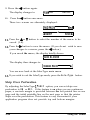
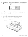
1. While holding down the LINE FEED button (draft mode) or the FORM
FEED button (Letter Quality mode), turn on the printer. The printer
beeps three times and the POWER and PAPER OUT lights come on.
o PAPER OUT
2. Press the PAPER SELECT button until the FRICTION light comes on.
Setting Up the Printer
1-17
3. Move the left edge guide until it rests against the guide mark.
4. Adjust the right edge guide to match the width of your paper.
Next, slide a sheet down between the edge guides until it meets
resistance.
Run the self test using paper wider than A4 size (8.27 inches).
1-18
Setting Up the Printer
5. Press the LOAD/EJECT button once to automatically load the paper.
6. Press the ON LINE button to start the self test.
Setting Up the Printer
1-19
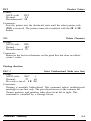
Note: To clear a paper jam, it is recommended that you set the printer
off line and use the FORM FEED or LINE FEED button. If it is necessary
to use the platen knob to clear the jam, be sure to turn the printer off
first.
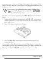
7. A list of your printer’s settings is printed first, followed by a series of
characters. The self test continues until the paper runs out or you
press the ON LINE button.
If the self test results are satisfactory and you wish to stop the test,
press the ON LINE button.
8. If paper is still loaded, press the LOAD/EJECT button to eject it. Then
turn off the printer.
WARNING: After you turn off the printer, always wait at
least five seconds before you turn it back on. Rapidly
switching the printer on and off can damage the printer.
1-20
Setting Up the Printer
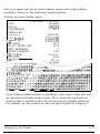
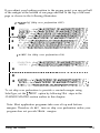
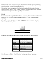
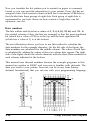
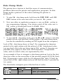
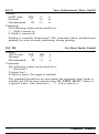
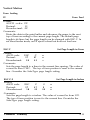
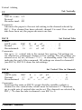
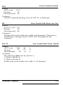
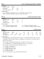
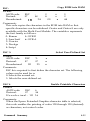
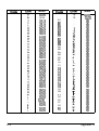
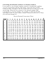
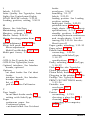
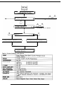
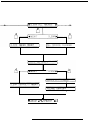
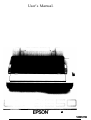
Part of a typical self test in Letter Quality mode with a black ribbon
installed is shown in the following sample printout.
Self test in Letter Quality mode
Current setting
FONT
Roman
PITCH
lOCPI
CONDENSED
Off
FORM LNG
Tractor
66LINE
C S F bin1
132LINE
,CSF b i n 2
132LINE
1 " SKIP
Off
AUTO TEAR OFF
Off
LEFT MARGIN
0
RIGHT MARGIN
136
CC TABLE
Italic
COUNTRY
USA
py
Bi-d
k--
-a/O1234567
,k/O12345678
-./0123456789
Courier
1 0 1 2 3 4 5 6 7 8 5 : ; <=>?@ABCDEFGHIJKLMNOPQRSTUVWX:
jO123456789 :;<=>?@ABCDEFGHIJKLMNOPQRSTUVWXY:
Note: When a black ribbon is installed, some lines of the self test
are printed in double-strike mode. Also, when the optional cut
sheet feeder is installed, the self test printout is slightly different.
For details, see the section on the cut sheet feeder in Chapter 7.
Setting Up the Printer
1-21
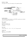
Connecting the Printer to Your Computer
Your LQ-2550 has two separate interface connections: a parallel interface
and an RS-232C compatible serial interface. If you are not sure which
one is required by your computer, check your computer manual for this
information.
If you have a suitable shielded cable, you should be able to connect to
most computers immediately.
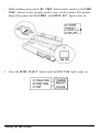
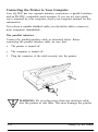
The parallel interface
Connect the parallel interface cable as described below. Before
connecting the parallel interface cable, be sure that:
l
The printer is turned off.
l
The computer is turned off.
1.
Plug the connector of the cable securely into the printer.
I.
v
1-22
WARNING: Do not plug more than one interface cable
into the printer at one time. This may damage the printer.
Setting Up the Printer
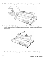
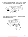
2. Squeeze the wire clips together until they lock in place on both sides
of the connector. (If you do not lock these clips into place, printed
results may be incorrect.)
3. If your cable has a ground wire, attach it to the ground connector
beneath the interface connector.
Setting Up the Printer
1-23
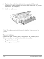
4. Plug the other end of the cable into the computer. (If there is a
ground wire at the computer end of the cable, attach it to the ground
connector of the computer.)
5. Attach the cable cover.
Note: The cable cover should always be attached when you use the
printer.
The serial interface
Connect the serial interface cable as described in the following steps.
Before connecting the serial interface cable, be sure that:
l
The printer is turned off.
l
The computer is turned off.
1-24
Setting Up the Printer
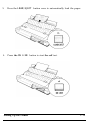
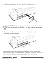
1.
Plug the connector of the cable securely into the printer.
WARNING: Do not plug more than one interface cable
into the printer at one time. This may damage the printer.
2. Using a screwdriver, secure the connector by tightening the screw on
each side of the connector.
Note: If the screws that come with the cable do not fit into the
connector lock nuts on the interface, you need to replace these lock
nuts with the optional lock nuts provided with the printer.
Setting Up the Printer
1-25
3. If your cable has a ground wire, attach it to the ground connector
beneath the interface connector.
4. Plug the other end of the cable into the computer. (If there is a
ground wire at the computer end of the cable, attach it to the ground
connector of the computer.)
1-26
Setting Up the Printer
5. Attach the cable cover.
Note: The cable cover should always be attached when you use the
printer.
Setting Up Your Application Software
Now that you have set up and tested the LQ-2550, you should make sure
that it works with the application programs you want to use. Most
application programs let you specify the type of printer you are using so
that the program can take full advantage of the printer’s features. Many
of these programs provide an installation or setup section that presents a
list of printers to choose from.
Setting Up the Printer
1-27
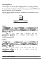
Choosing from a menu
Because the family of Epson printers shares many commands, you can
use an application program even if it does not list the LQ-2550 on its
printer selection menu. If the LQ-2550 is not listed, select the first printer
available on the following list:
LQ-2500
LQ-1050 (LQ-850)
LQ-1000 (LQ-800)
LQ-500
LQ-1500
If none of these printers is listed, select the first one available on the
following list:
LQ
EX
FX
LX
RX
MX
Epson printer
Standard printer
Draft printer
If you are printing in color, it is recommended that you choose LQ-2550
or LQ-2500.
To use all the features of the LQ-2550, however, it is best to use a
program with the LQ-2550 on its menu. If your program does not list
this printer, contact the software manufacturer to see if an update is
available. For further information on using software, see Chapter 4.
1-28
Setting Up the Printer
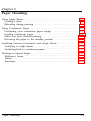
Chapter 2
Paper Handling
Using Single Sheets . . . . . . . . . . . . . . . . . . . . . . . . . . . . . . . . . . . . . . . . . . 2-2
Loading a sheet . . . . . . . . . . . . . . . . . . . . . . . . . . . . . . . . . . . . . . . . . . . 2-2
Reloading during printing . . . . . . . . . . . . . . . . . . . . . . . . . . . . . . . . . . 2-5
Using Continuous Paper . . . . . . . . . . . . . . . . . . . . . . . . . . . . . . . . . . . . . 2-5
Positioning your continuous paper supply . . . . . . . . . . . . . . . . . . . . . 2-5
Loading continuous paper . . . . . . . . . . . . . . . . . . . . . . . . . . . . . . . . . . 2-6
When you have finished printing . . . . . . . . . . . . . . . . . . . . . . . . . . . 2-13
Reversing the paper to the standby position . . . . . . . . . . . . . . . . . . 2-14
Switching between Continuous and Single Sheets . . . . . . . . . . . . . . . . 2-16
Switching to single sheets . . . . . . . . . . . . . . . . . . . . . . . . . . . . . . . . . . 2-16
Switching back to continuous paper . . . . . . . . . . . . . . . . . . . . . . . . . 2-19
Printing on Special Paper . . . . . . . . . . . . . . . . . . . . . . . . . . . . . . . . . . . . 2-22
Multi-part forms . . . . . . . . . . . . . . . . . . . . . . . . . . . . . . . . . . . . . . . . . 2-22
Labels . . . . . . . . . . . . . . . . . . . . . . . . . . . . . . . . . . . . . . . . . . . . . . . . . . 2-23
Envelopes . . . . . . . . . . . . . . . . . . . . . . . . . . . . . . . . . . . . . . . . . . . . .....2-26
Paper Handling
2-1
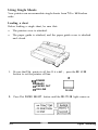
Using Single Sheets
Your printer can accommodate single sheets from 7.2 to 14.3 inches
wide.
Loading a sheet
Before loading a single sheet, be sure that:
l
The printer cover is attached.
l
The paper guide is attached, and the paper guide cover is attached
and closed.
1. Be sure that the printer is off line. If it is not, press the ON LINE
button to set the printer off line.
cl
0 POWER
0 READY
o PAPER OUT
n ON LINE
a
ON LINE
2. Press the PAPER SELECT button until the FRICTION light comes on.
2-2
Paper Handling
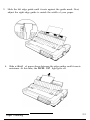
3. Slide the left edge guide until it rests against the guide mark. Next,
adjust the right edge guide to match the width of your paper.
4. Slide a sheet of paper down between the edge guides until it meets
resistance. At this time, the PAPER OUT light goes off.
Paper Handling
2-3
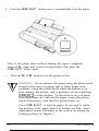
5. Press the LOAD/EJECT button once to automatically load the paper.
Note: If the platen turns without loading the paper, completely
remove the paper and re-insert it more firmly; then press the
LOAD/EJECT button again.
6. Press the ON LINE button to set the printer on line.
1.
77
WARNING: Never advance the paper using the platen knob
except in the case of a paper jam or other paper feed
problem. Using the platen knob while the printer is on
may damage the printer, and it produces an error message
(ERFi.OR 12 ) on the display. To clear this error you must
turn the printer off, take out the paper (using the platen
knob if necessary), and turn the printer back on.
Press LOAD/EJECT to load the paper. If you need to adjust
the position of the paper after it is loaded, use the microadjustment feature described in the section on setting the
loading position in Chapter 3.
2-4
Paper Handling
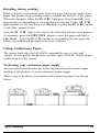
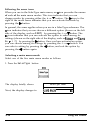
Reloading during printing
When you print a document more than one page long using single sheet
paper, the printer stops printing when it reaches the bottom of the paper.
When this happens, either the ON LINE light goes off automatically or it
may remain on, depending on your application software. If the ON LINE
light remains on, the first thing you should do is press the ON LINE button
to take the printer off line.
Once the ON LINE light is off, remove the sheet that has just been printed
(if necessary, press the FORM FEED button to eject the page) and load a
new sheet. Press the ON LINE button to start printing the next page and
follow any additional prompts from your software.
Using Continuous Paper
The tractor built into the LQ-2550 is remarkably easy to load and
operate. Its low-profile design takes up little space and can handle paper
widths from 4 to 16 inches.
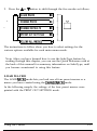
Positioning your continuous paper supply
An important consideration for achieving smooth and accurate paper
feeding is the position of your continuous paper supply.
Three ways to position your printer and continuous paper are shown
below.
Paper Handling
2-5
Be sure to align your paper supply with the paper loaded in the tractor
so that the paper feeds smoothly into the printer.
Loading continuous paper
Before loading continuous paper, be sure that:
l
The printer is turned on.
l
The printer cover is attached.
l
The paper guide is removed.
l
l
2-6
The paper guide cover is attached and fully open from the rear, as
shown in the illustration.
The cable cover is attached.
Paper Handling
1. Be sure that the printer is off line. If it is not, press the ON LINE
button to set the printer off line. Then press the PAPER SELECT button
until the TRACTOR light comes on.
2. Release the sprocket lock levers and slide the left sprocket unit all the
way to the left and lock it in place. Next, slide the right sprocket unit
to roughly match the width of your paper but do not lock it.
Paper Handling
2-7
3. Slide the paper support to a point midway between the sprocket
units.
4. Open the sprocket covers.
2-8
Paper Handling
5. Fit the first four holes in the continuous paper over the pins of the
sprocket units.
6. Close the sprocket covers.
Paper Handling
2-9
7. Slide the right sprocket unit to a position where the paper is straight
and has no wrinkles, and then lock it into place.
Note: Make sure the first sheet of paper has a clean, straight edge so
that the paper can feed smoothly into the printer.
8. Reattach the paper guide. Then slide the edge guides together so that
they meet at about the middle of the paper’s width.
2-10
Paper Handling
9. Pull the paper guide in the direction of the arrow in the illustration.
10. Push down the paper guide.
Note: The paper guide prevents outgoing continuous paper from being
pulled back into the printer.
Paper Handling
2-11
11. Close the paper guide cover.
12. Press the LOAD/EJECT button to feed the paper to the loading
position.
Note: If you press the LOAD/EJECT button when continuous paper is
already loaded, the paper is reversed to the standby position.
2-12
Paper Handling
13. Press the ON LINE button to set the printer on line.
The printer remembers this loading position and advances each page to
the same position. Never adjust the loading position using the platen
knob. If you need to adjust the loading position, use the microadjustment feature. See the section on setting the loading position in
Chapter 3.
Note: Before you begin printing, be sure to check the page length
and skip over perforation settings, and readjust the settings if
necessary. See the sections on page length and skip over perforation in
Chapter 3.
Also, if you are using preprinted or multi-part forms or labels, or if
you wish to obtain the highest quality graphics, it is recommended
that you use the optional pull tractor. See the pull tractor section in
Chapter 7.
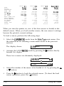
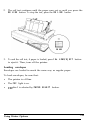
When you have finished printing
When you are ready to tear off the continuous paper printout, you can
either use the automatic short tear-off function or use the following steps.
(For more information on the short tear-off function, see Chapter 3.)
1. After printing is completed, set the printer off line.
Paper Handling
2-13
2. Press the FORM FEED button to feed the paper forward. Then tear it
off at the perforation.
Note: If the perforation of the paper is not fed past the edge of the
paper guide the first time, press the FORM FEED button again. Do not
use the platen knob to feed the paper.
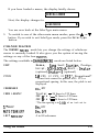
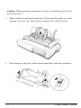
Reversing the paper to the standby position
After you have tom off the last page of printed paper, if you wish to
reverse-feed the paper remaining in the printer to the standby position,
follow the steps below.
When continuous paper is in the standby position, the holes at the top of
the first sheet stay fitted over the pins of the sprocket unit. When the
paper is in this position, you can switch to single sheet paper (see the
instructions in this chapter), reload the continuous paper, or remove the
continuous paper.
2-14
Paper Handling
Before reversing the paper, be sure that:
l
The printer is turned on.
l
The TRACTOR light on the control panel is on.
1. Check to see that the printer is off line. If it is not, press the ON LINE
button to set the printer off line.
2. Press the LOAD/EJECT button once. This feeds the loaded paper
backward to its standby position. If the paper does not reach this
position, the printer briefly displays Cannot Back Out. Press the
LOAD/EJECT button as many times as necessary to back out the paper
to its standby position. (Do not use the platen knob to back out the
paper. )
Paper Handling
2-15
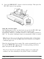
Switching between Continuous and Single Sheets
Even with continuous paper loaded in the printer, you can easily switch
to single sheet printing without removing the continuous paper from the
tractor.
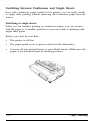
Switching to single sheets
When you are finished printing on continuous paper, you can reversefeed the paper to a standby position so you can switch to printing with
single sheet paper.
Before you start, be sure that:
l
The printer is off line.
l
The paper guide cover is open as shown in the illustration.
l
You tear off any printed sheets or extra blank sheets. (Make sure the
paper is not advanced past its loading position.)
2-16
Paper Handling
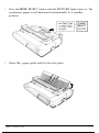
1. Press the PAPER SELECT button until the FRICTION light comes on. The
continuous paper is fed backward automatically to a standby
position.
2. Raise the paper guide until it locks into place.
Paper Handling
2-17
3. Close the paper guide cover.
4. Slide the left edge guide until it rests against the guide mark. Next,
adjust the right edge guide to match the width of your paper.
2-18
Paper Handling
5. Slide a sheet of paper down between the edge guides until it meets
resistance.
6. Press the LOAD/EJECT button once to automatically load the paper.
7. Press the ON LINE button to set the printer on line.
Switching back to continuous paper
It is also easy to switch back to printing with continuous paper.
Paper Handling
2-19
Before switching back, be sure that:
l
The printer is off line.
l
The paper guide cover is open as shown in the illustration.
1. Press the PAPER SELECT button until the TRACTOR light comes on. If a
single sheet is loaded, it is ejected automatically and the continuous
paper is fed to the loading position.
2-20
Paper Handling
2. Slide the edge guides together so that they meet at about the middle
of the paper’s width.
3. Lower the paper guide onto the back of the printer.
Paper Handling
2-21
4. Close the paper guide cover.
5. Press the ON LINE button to set the printer on line.
Printing on Special Paper
In addition to using single sheets and continuous paper, your printer
can also print on a wide variety of paper types, including multi-part
forms, labels, and envelopes. Your printer can sense the paper
thickness and width automatically. You need not adjust the paper
thickness manually.
Note: If you are printing preprinted or multi-part forms or labels, it
is recommended that you use the optional pull tractor to print. See
the pull tractor section in Chapter 7.
Also, when you print on multi-part forms, labels, or envelopes, be
sure that your application program settings keep the printing
entirely within the printable area. That is, you should not print any
closer than one-half inch from either side of the paper for multipart forms and labels. For information on the printable area for
envelopes, see page 2-27.
Multi-part forms
With the built-in tractor unit, your printer can print on continuous
multi-part forms. You can use multi-part forms that have up to six parts
including the original.
2-22
Paper Handling
Multi-part paper is loaded the same way as continuous paper. For
details, see the section on loading continuous paper in this chapter.
Before loading the multi-part forms, press the PAPER SELECT button until
the TRACTOR light comes on.
WARNING: Do not load or print on multi-part forms if the
FRICTION light or CSF light is on.
Labels
If you need to print labels, choose the type of label that is mounted on a
continuous backing sheet with sprocket holes for use with the tractor. Do
not use single sheet labels on a shiny backing sheet because they almost
always slip a little if fed by friction alone.
You load labels the same way that you load continuous paper. See the
section on loading continuous paper in this chapter.
WARNING: Never feed labels backward through the printer.
Labels can easily come off the backing and jam the printer.
Also, never use the LOAD/EJECT button to eject labels. If a
label does become stuck in the printer mechanism, see your
authorized Epson dealer for assistance.
Since labels are especially sensitive to temperature and
humidity, always use them under normal operating
conditions.
Paper Handling
2-23
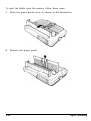
To eject the labels from the printer, follow these steps:
1. Raise the paper guide cover as shown in the illustration.
2. Remove the paper guide.
2-24
Paper Handling
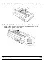
3. Tear off the sheet of labels at the perforation behind the push tractor.
4. Press the ON LINE button to set the printer off line. Then press the
FORM FEED button to eject the labels. (Remember not to use the
LOAD/EJECT button to eject labels.)
Paper Handling
2-25
Envelopes
You can print on a variety of envelopes - including air mail, plain, or
bond envelopes - using the single sheet loading feature described in this
chapter. Chapter 7 describes using envelopes with the cut sheet feeder.
When loading an envelope, you may have to press down on it slightly.
Then press the LOAD/EJECT button to load the envelope.
If it is necessary to eject the printed envelope, press the ON LINE button to
set the printer off line. Then press the LOAD/EJECT button.
2-26
Paper Handling
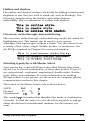
WARNING: When you print on envelopes, be sure that your
application program settings keep the printing entirely within
the printable area shown below.
8.5 mm
(0.33”) or more
3mm
(0.22”)
22 mm
(0.87”) or more
or more
Note: If the printed results are faint, use the PLATEN GAP ADJUST
button to adjust the distance between the print head and the platen.
Paper Handling
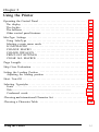
Chapter 3
Using the Printer
Operating the Control Panel . . . . . . . . . . . . . . . . . . . . . . . . . . . . . . . . . .
The display . . . . . . . . . . . . . . . . . . . . . . . . . . . . . . . . . . . . . . . . . . . . . .
The lights.. . . . . . . . . . . . . . . . . . . . . . . . . . . . . . . . . . . . . . . . . . . . . . .
The buttons . . . . . . . . . . . . . . . . . . . . . . . . . . . . . . . . . . . . . . . . . . . . . .
Other control panel features . . . . . . . . . . . . . . . . . . . . . . . . . . . . . . . .
3-2
3-2
3-3
SelecType Settings . . . . . . . . . . . . . . . . . . . . . . . . . . . . . . . . . . . . . . . . . .
Using SelecType . . . . . . . . . . . . . . . . . . . . . . . . . . . . . . . . . . . . . . . . .
Selecting a main menu mode . . . . . . . . . . . . . . . . . . . . . . . . . . . . . . .
LOAD MACRO . . . . . . . . . . . . . . . . . . . . . . . . . . . . . . . . . . . . . . . . .
CHANGE MACRO . . . . . . . . . . . . . . . . . . . . . . . . . . . . . . . . . . . . . .
CHANGE DEFAULTS . . . . . . . . . . . . . . . . . . . . . . . . . . . . . . . . . . . .
PRINT OUT SETTINGS . . . . . . . . . . . . . . . . . . . . . . . . . . . . . . . . . .
CLEAR ALL MACROS . . . . . . . . . . . . . . . . . . . . . . . . . . . . . . . . . . .
3-8
3-10
3-12
3-13
3-4
3-8
3-15
3-18
3-23
3-24
Page Length.. . . . . . . . . . . . . . . . . . . . . . . . . . . . . . . . . . . . . . . . . . . . . . 3-26
Skip Over Perforation . . . . . . . . . . . . . . . . . . . . . . . . . . . . . . . . . . . . . . 3-28
Setting the Loading Position . . . . . . . . . . . . . . . . . . . . . . . . . . . . . . . . . 3-30
Adjusting the loading position . . . . . . . . . . . . . . . . . . . . . . . . . . . . . 3-30
Short Tear-Off . . . . . . . . . . . . . . . . . . . . . . . . . . . . . . . . . . . . . . . . . . . . . 3-31
Selecting Typestyles . . . . . . . . . . . . . . . . . . . . . . . . . . . . . . . . . . . . . . . . 3-33
Fonts . . . . . . . . . . . . . . . . . . . . . . . . . . . . . . . . . . . . . . . . . . . . . . . . . . 3-34
Pitch....................................................................................................................
3-37
Condensed mode . . . . . . . . . . . . . . . . . . . . . . . . . . . . . . . . . . . . . . . . 3-38
Choosing an International Character Set . . . . . . . . . . . . . . . . . . . . . . . 3-39
Choosing a Character Table . . . . . . . . . . . . . . . . . . . . . . . . . . . . . . . . . 3-40
Using the Printer
3-1
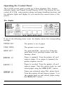
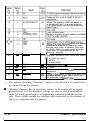
Operating the Control Panel
The LQ-2550 control panel is made up of three elements: the buttons,
indicator lights, and Liquid Crystal Display (LCD). The buttons let you
control all of the main printer settings and paper handling functions, and
the indicator lights and display let you monitor the current status of the
printer.
The display
0 POWER
0 READY
0 PAPER OUT
o ON LINE
If any of the following states occur, the display shows the corresponding
message.
The printer is out of paper.
The printer cover is open.
The print head has become hot. When the
print head cools, printing resumes and this
message clears.
Paper is jammed. Turn the printer off and
remove paper. If no paper is jammed, the
printer requires service.
Paper is crooked. Turn the printer off and
remove paper. Turn the printer back on, and
reload paper using the LOAD/EJECT button.
Paper was advanced using the platen knob.
Turn the printer off and remove paper. Turn
the printer back on and reload paper using
the LOAD/EJECT button.
3-2
Using the Printer
The lights
0
0
13
o
POWER
READY
PAPER OUT
ON LINE
a
ON LINE FORM FEED LINE FEE0 LOAOIEJECT
POWER (green):
On when the printer is turned on and
power is supplied.
READY (green):
On when the printer is ready to accept
input data. This light flickers while data is
received.
PAPER OUT (red):
On when the printer is out of paper.
ON LINE (green):
On when the printer can receive and print
data from the computer. If this light
flickers, the print head is overheating.
Printing resumes when the print head
cools.
TRACTOR (green):
On when tractor feed is selected by the
PAPER SELECT button.
FRICTION (green):
On when friction feed is selected by the
PAPER SELECT button.
CSF (green):
On when cut sheet feeder mode is selected
by the PAPER SELECT button.
CONDENSED (green):
On when condensed mode is selected by
the CONDENSED button, SelecType setting,
or software command.
TEAR OFF (orange):
On when tear-off mode is selected.
MICRO FEED (orange):
On when micro-adjustment feature is
selected.
Using the Printer
3-3
PLATEN GAP ADJUST :
(orange)
On when platen gap adjust mode is
selected.
SelecType (orange):
On when SelecType mode is selected.
4 A V b (yellow):
These arrows prompt the user when
SelecType mode, tear-off mode, micro-feed
mode, or platen gap adjust mode is
selected.
The buttons
O N L I N E F O R M F E E D L I N E FEED LOAOIEJECT
ON LINE:
This button controls the printer’s on line/
off line status. When the printer is on line,
the ON LINE light on the left side of the
control panel is on and the printer can
receive and print data from the computer.
In SelecType mode, this button may be
used to change the SelecType settings.
FORM FEED:
When the printer is off line, this button
ejects a single sheet of paper or advances
continuous paper to the top of the next
page. In SelecType mode, this button
changes the SelecType settings.
3-4
Using the Printer
LINE FEED:
When the printer is off line, this button
feeds the paper one line, or held down,
feeds the paper continuously. In SelecType
mode, this button changes the SelecType
settings.
LOAD/EJECT:
When the printer is off line, this button
loads or ejects the paper. In SelecType
mode, this button changes the SelecType
settings.
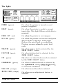
FONT:
Hold down this button until the display
shows the desired font. Pressing the FONT
button displays fonts in the following
order:
Draft, Roman, Sans Serif, Courier,
Prestige, Script, OCR-B, OCR-R,
ORATOR, ORATOR-S
Orator and Orator-S are only available with
the optional Multi-Font Module. See the
section on fonts in this chapter for more
information.
PITCH:
Using the Printer
Hold down this button until the display
shows the desired pitch. You can choose 10,
12, or 15 CPI (characters per inch) or
Proportional. See the section on pitch in this
chapter for more information.
3-5
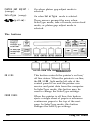
CONDENSED:
Press this button to select either condensed
or normal printing. The selected mode is
displayed. In condensed mode, all
characters are printed at approximately
60% of their normal width. This mode
cannot be combined with 15 CPI (set by the
PITCH button).
MICRO FEED:
Turns on and off the micro-adjustment
feature. In micro-feed mode, the LINE FEED
(V) button is used to feed the paper slightly
backward and #he FORM FEED (A) button is
used to feed the paper slightly forward to
adjust the print position, short tear-off
position, or loading position. The sections
on short tear-off and adjusting the loading
position in this chapter have more
information on this feature.
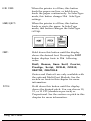
PLATEN GAP ADJUST:
Selects or deselects the platen gap adjust
mode. If the printing is too dark or too
faint, you can widen or narrow the platen
gap to achieve the desired printing results.
When this mode is selected, the display
changes to:
GhP
.
.
.
.
..DDDDD.
Press the ON LINE (4 ) button to widen the
gap between the platen and print head.
Press the LOAD/EJECT ( b) button to narrow
the gap. An increasing number of ) ‘s
indicates a narrowing gap.
3-6
Using the Printer
SelecType:
Selects or deselects the SelecType mode. When
this mode is selected, the ON LINE (4), FORM
FEED(A), LINE FEED (V),and LOAD/EJECT
( .) buttons can be used as SelecType panel
buttons. The display lets you monitor the
SelecType settings. See the section on
SelecType in this chapter for details.
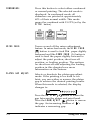
w
TEAR
OFF
TEAROFF:
Press this button to feed the perforation of
continuous paper to the tear-off edge of the
printer. After tearing off the paper, press this
button again to feed the paper backward to
the loading position. You can also make this
feature easier to use by setting the AUTO TEAR
OFF option with SelecType. See the short
tear-off section in this chapter for more
information.
PAPER SELECT:
When the printer is off line, press this button
to select the paper handling system. The
selected system is shown on the display. The
paper handling system is selected in the
following order:
Tractor, Friction, CSF Bin 1,
CSF Bin 2
Using the Printer
3-7
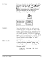
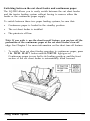
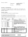
Other control panel features
Self test:
By holding down the FORM FEED button (for
draft mode) or LINE FEED button (for Letter
Quality mode) while you turn on the printer,
you can start the printer’s self test. The self
test printout lets you check the current
settings and operating status of the printer.
See the section on testing the printer in
Chapter 1 for more information.
Data dump:
By holding down both the LINE FEED and
FORM FEED buttons while you turn on the
printer, you turn on the data dump mode.
This feature allows advanced users to find
the cause of communication problems
between the computer and printer. See the
section on the data dump mode in Chapter 6.
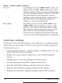
SelecType Settings
SelecType on the LQ-2550 brings a new dimension to printing. With
SelecType you can control almost every aspect of printer operation.
SelecType lets you:
l
l
Use four preset macros - stored groups of settings that you can
recall with the touch of a button
Replace the preset macros with your own custom-designed
macros
l
Change up to 17 printer settings from SelecType
l
Choose among the LQ-2550’s eight built-in fonts
l
Print the LQ-2550’s settings with the touch of a button
l
Monitor the LQ-2550’s settings with the LCD display
l
Change the LQ-2550’s default settings without DIP switches.
3-8
Using the Printer
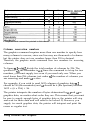
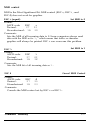
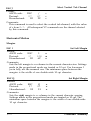
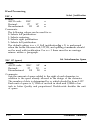
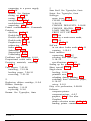
The four preset macros cover these general applications: Letter Quality
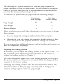
printing/word processing, draft printing/word processing, spreadsheets,
and graphics. You can also create your own macros with any of the LQ’s
settings.
MACRO #l
Preset macro #l is set for Letter Quality
printing/word processing in the Roman font.
It can be used for word processing or any
application where you want a polished
result. You can also use enhancements and
print styles, i n c l u d i n g italic, emphasized,
a n d
d o u b l e - w i d t h ,
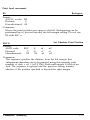
MACRO #2
Preset macro #2 is set for draft
printing/word processing to produce highspeed, d r a f t q u a l i t y p r i n t i n g . I t c a n b e
used for word processing to print rough
drafts, or for any job you need printed in
a h u r r y . You can also use enhancements and
p r i n t s t y l e s , i n c l u d i n g itall’c, e m p h a s i z e d ,
a n d d::::::l II::::::) I ,.,. I! Ur::::r X. E::!: ~~~~~.~~ II,P,,II ::ii.. II::::::~ ‘I:::.. 1k11 ,.,
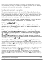
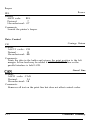
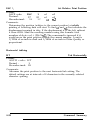
MACRO #3
SALES REPORT
Jan Feb Mar
Qr
May Jun
J. Smith
784
648
1. Jones
714
074
789
740
L. Williams
Using the Printer
756
548
475
750
655
152
852
154
841
654
a85
887
3-9
MACRO #4
1
There are no switches to reset or commands to send. In fact, the
LQ-2550 has no DIP switches. You simply load the macro you want,
then print. All these functions can be controlled through SelecType.
Using SelecType
To enter SelecType mode, simply press the SelecType button.
0
II
SelecType
Before you use SelecType, make sure that the LQ-2550 is not printing.
The printer must complete its print job before you enter SelecType. If
you have turned the printer off line during a print job, turn the printer
back on line and let the LQ-2550 finish printing before you enter
SelecType mode.
3-10
Using the Printer
Note: Your application may override your Selectype settings. Some
application programs are designed to control the same settings you
choose with SelecType by sending certain software commands before
printing. Because these commands cancel SelecType settings, you
should use the program instead of SelecType to select the affected
setting.
You can exit SelecType at any time by pressing this button once more.
Note that you must exit SelecType before printing a document. If you
press the SelecType button after you set a macro but before you save it,
those settings are temporarily used as current settings until the printer is
turned off, but are cleared when the printer is turned back on.
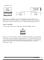
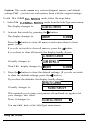
The SelecType main menu lists the five modes that let you control
printer functions and operations. The five main menu modes are:
:LrJflDMfKRO:
This mode lets you load one of the four
macros to accommodate your own printing
needs.
:CHflNGEl'MCRO:
This mode lets you change the current printer
settings (such as font and form length), with
the option of saving these changes to create
your own macros.
:CHBNGEDEFAlJLTS
This mode lets you define the default settings
(such as interface and baud rate) that will be in
effect each time you turn on the printer.
:PRINTOUT
SETTINGS:
This mode prints out the current printer
settings, the settings for the four macros, and
the default settings.
:CLEflRALL
t'lC1CRDS:
This mode returns all of the current printer
settings, macro settings, and default settings to
the preset values.
Using the Printer
3-11
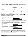
Following the arrow icons
When you are in the SelecType main menu, an : icon precedes the names
of each of the main menu modes. This icon indicates that you can
change modes by pressing either the ^ or V button. The F icon to the
right of the mode name indicates that you can activate the mode by
pressing the b button.
In general, the same applies when you are in a SelecType submenu. The
: icon indicates that you can choose a different option (shown on the left
side of the display, such as FONT) by pressing the ^ or V button. The
F icon indicates that you can activate the option to select among its
settings (shown on the right side of the display, such as Roman and Sans
Se P i f) by pressing the F button. Once you have activated an option,
you can choose among its settings by pressing the ^ or V button. You
can select a setting by pressing the 4 button, and exit the option by
pressing the 4 button again.
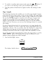
Selecting a main menu mode
Select one of the five main menu modes as follows:
1. Press the SelecType button.
SelecType
a
The display briefly shows:
Next, the display changes to:
3-12
SelecType MODE
SLDfiDMfKRO
b
Using the Printer
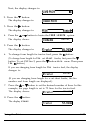
2. Press the A or V button to shift through the five modes as follows.
-
A
a
-
SLOADNFICRU
b
:CHfiNGEMfKRO
.I
SCHCINGEDEFAULTS
b
:PRINTOUTSETTINGS
b
:CLEFIRFtLLMCROS
b
v
a
The instructions to follow show you how to select settings for the
various options available for each main menu mode.
Note: After you have learned how to use the SelecType feature by
reading through this chapter, you can use the Quick Reference card at
the back of this manual for summary information on SelecType, until
you become accustomed to using this feature.
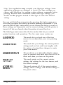
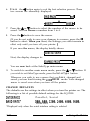
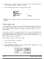
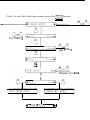
LOAD MACRO
The LOflD MfiCRO mode lets you load one of four preset macros or a
macro you have created using the CHhNBE I’WICRO mode.
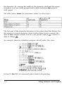
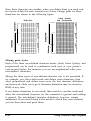
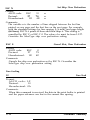
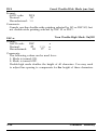
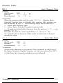
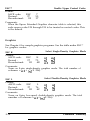
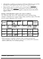
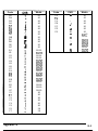
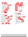
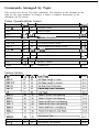
In the following sample, the settings of the four preset macros were
printed with the PRINT OUT SETTINGS mode.
Using the Printer
3-13
FONT
PITCH
CONDENSED
FORM LNG
Tractor
CSF bin1
CSF bin2
1" SKIP
AUTO TEAR OFF
LEFT MARGIN
RIGHT MARGIN
CG TABLE
COUNTRY
PRINT DIR.
COLOR
Macro #1
ROIWXI
lOCPI
Off
Macro #2
Draft
lOCPI
Off
Macro #3
Draft
lOCPI
On
Macro t4
ROlnEXIl
lOCPI
Off
66LINE
132LINE
132LINE
Off
Off
0
136
Italic
USA
Bi-d
Black
66LINE
132LINE
132LINE
Off
Off
0
136
Italic
USA
Bi-d
Black
66LINE
132LINE
132LINE
Off
Off
0
136
Italic
USA
Bi-d
Black
BlLINE
132LINE
132LINE
Off
Off
0
136
Italic
USA
Bi-d
Black
When you turn the printer on, one. of the four macros is loaded as the
default macro. When you load another macro, the new macro’s settings
become the printer’s current settings.
To load a macro, perform the following steps.
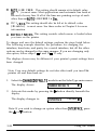
1. Select the LUfiD NfKRU mode from the SelecType main menu. (See
the instructions for selecting a main menu mode in the previous
section.)
The display shows:
2.
:LUfiD MACRO
b
Activate the LOAD MfKRO mode by pressing the F button directly
beneath the display.
These two screens are alternately displayed:
#r-t+
LOF~DMIJCRU
I
l FIEURT
LUflD,
3.
Select the number of the macro to be loaded (1-4) by pressing the A
or V button.
4.
Press the b button to load the selected macro. (To abort the load
macro operation, press the 4 button.)
3-14
Using the Printer
If you have loaded a macro, the display briefly shows:
MfKRO#nLOfiDED
Next, the display changes to:
:LO~IDMFICRO
b
You are now back at the SelecType main menu.
5. To switch to one of the other main menu modes, press the A or V
button. If you wish to exit SelecType mode, press the SelecType
button.
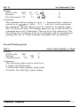
CHANGE MACRO
The CHANGE PlACRO mode lets you change the settings of whichever
macro is currently loaded. It also gives you the option of saving the
settings as any of the four rn-acres.
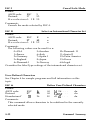
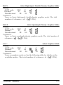
The settings available in CHhNGE MCRO mode are listed below.
FONT
Roman, Sans Serif, Courier, Prestige,
Script, OCR-B, OCR-FI, Draft., Orator
(optional), Orator-S (optional)
PITCH
18 CPI, 12 CPI, 15 CPI*, Proportional*
* Some fonts cannot be printed in 15 CPI or
proportional spacing. In this case, the pitch is not
displayed.
CONDENSED
On, Off
FORM LENGTH*
Tractor - 24 lines to 132 lines
CSF B i n 1 - 24 lines to 132 lines
CSF B i n 2 - 24 lines to 132 lines
* The line spacing is in 1/6th of an inch units.
1” SKIP
On, Off
fWTOTEfIROFF
On, Off
LEFT l”MRCiIN*
0 to 80 columns
Using the Printer
3-15
RICiHTMARGIN*
1 to 136 columns
*The column spacing is based on a pitch of
10 CPI.
CG TABLE
I t a l i c , G r a p h i c , Download
COUNTRY
IJM, France, Germany, IJK, Denmarkl,
Sweden, Italy, Spainl, Japan,
Norway, Denmark2, Spain2, Latin
America, Korea, Legal
PRINT DIR.
Bi-directional, Uni-directional
CiiLOR
Black, Magenta, Cyan, Uil3let, Yellcfw,
Red, Green
The changes you make are temporarily made to the current macro’s
settings (until you turn off the printer), but you can save the changes as
any of the four macros. Changed macros that you save remain in effect
even after you turn off the printer.
The following example describes the procedure for changing the FONT
option, but the other options (with the exception of FORM LENGTH) can
be changed in the same manner. (The procedure for setting FORM
LENGTH is described later in this chapter.) The displays shown may be
different if your printer’s preset settings have been changed.
Note: The following options are described in more detail later in this
chapter: FORMLENGTH, 1” SKIP, f&lTOTEAROFF, FONT, PITCH,
COUNTRY, andCG TABLE.
3-16
Using the Printer
To change and save a macro, perform the steps described below.
1.
Select the CHhNGE MACRD mode from the SelecType main menu. (See
the instructions for selecting a main menu mode earlier in this
chapter.)
The display shows:
SCHCINGEMKRO
b
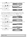
2. Activate this mode by pressing the b button directly beneath the
display.
The display changes to:
:FONT
Roman b
Note: The + icon preceding FONT indicates that you can change to one
of the other options, such as right margin or color, by pressing the V
or A button to display the option.
3. To select a font, press the ä
The display changes to:
4.
button.
4 FONT
Ronat-
Press the V button to shift through the available fonts. (Press the A
button to shift through the fonts in reverse order.)
For the purposes of this example, display Sans Serif by pressing
the V button.
The display changes to:
5.
4 FONT
SansSerifI
Press the 4 button to select Sans Serif.
The display changes to:
:FONT
SansSerifb
Note: At this point you can again change the option at the left side of
the display by pressing the A or V button. If you do this, begin again
at step 3 to change the settings for the option.
Using the Printer
3-17
6. Press the 4 button again to exit the font selection process. These
two screens are alternately displayed:
SCIUEMf3CRO
.
#n:
&
4fiBORT
SfV.JEb
7. Press the A or V button to select the number of the macro to be
saved. You can choose a number from 1 to 4.
8. Press the b button to save the macro.
(If you do not wish to save your changes to a macro, press the 4
button to abort. When you abort, the settings you select remain in
effect only until you turn off your printer. )
If you save the macro, the display briefly shows:
MflCRU#nSFIUED
Next, the display changes to:
:CHFINGEMFlCRU
b
You are now back at the SelecType main menu.
9. To switch to another main menu mode, press the A or V button. If
you wish to exit SelecType mode, press the SelecType button.
Whenever you wish to use a macro that you have changed and
saved, you can load it using the LUAD MACRO mode. Your changed
macro is saved even when you turn off the printer.
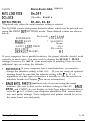
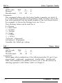
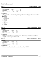
CHANGE DEFAULTS
The defaults are the settings in effect when you turn the printer on. The
following is a list of possible default settings for the LQ-2550.
INTERFRCE
Parallel, Serial
BAUDRflTE*
3G18, 68@, 12QB, 2488, 4888, 968Q,
19288 BPS
*Displayed only when the serial interface setting is selected
3-18
Using the Printer
PARITY *
None, Even, Odd, Ignore
FlUTOLINEFEED
On, Off
DCl/DC3
Disable, Enable
DEFfYJLT MCR#
#l, #21 #3, #4
*Displayed only when the serial interface setting is selected
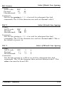
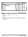
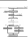
The LQ-2550 comes with preset default values, which can be printed out
using the PRINT GLJT SETTINGS mode. These default values are shown
below.
D e f a u l t , set.t;ing
Parallel
INTERFACE
* 9600RPS
BAUD RATE
*
None
PARITY
Off
AUTO L,INE FEED
Disable
DCl/DC3
DEFAUI,T MACRO
#3
If your computer has a parallel interface, the preset defaults should work
correctly in most cases. You may wish to change the DEFAULT MACRO
settings, however, to match your usual style of printing. Here are a few
additional tips on setting the defaults.
l
l
INTERFFICE: If your computer has a serial interface, you need to
change the interface setting to Serial. (If you are using an optional
interface board, be sure that the interface setting is Pa r a 11 e 1,
regardless of what type of interface it actually is. See the section on
interface boards in Chapter 7 for more information.)
BFllJD RfiTE, Pf?RIT’r’: Set these only if you are using the serial
interface. (Be sure to first set the interface setting to Serial . BALJD
RfiTE and PARITY do not display in SelecType unless the interface is
set to Se r i a 1.) Check your computer manual for the correct baud
rate and parity settings. Your computer and printer should be set to
the same baud rate and parity.
Using the Printer
3-19
f3UTO LINE FEED: This setting should remain at its default value
(0 f f ) in most cases. Most applications send automatic line feeds at
the end of every line. If all of the lines are printing on top of each
other, then set FIIJTO LINE FEED to On.
DC 1 /DC3: This setting should also be left at its default value
(Disable) in most cases. See these codes in Chapter 8 for more
information.
DEFWJLT MfKRO: This setting controls which macro is loaded when
you turn on the printer.
To change and save the default settings, perform the steps listed below.
The following example describes the procedure for changing the
interface, baud rate, and parity for a serial interface, but all the other
options can be changed in the same manner. If you are changing only
one option, follow steps 1 - 4 and 13 - 17 only.
The displays shown may be different if your printer’s preset settings have
been changed.
Note: Your new default settings do not take effect until you turn the
printer off and then back on.
1. Select the CHfINGE DEFfWLTS mode from the SelecType main menu.
The display shows:
SCHfiNGEDEFAULTS
b
2. Activate this mode by pressing the b button directly beneath the
display.
The display changes to:
SINTERFCICE
Parallel b
Note: If you wish to change an option other than INTERFfKE, press
the A or V button.
3-20
Using the Printer
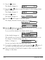
3. Press the F button to indicate that you wish to change the setting.
The display changes to:
4INTERFRCE
Parallel:
4. Press the A or V button to switch the display to Se r i a 1.
The display changes to:
) 4 INTERFIXE
Serial:1
5. Press the 4 button.
The display changes to:
:INTERFf%E
Serial,
Note: If you are changing only one option, skip to step 14 at this
point. The other steps show you how to change two other options,
following the same method given for the INTERFACE option.
6. Press the V button to switch the display to BAIJD Rf3TE.
The display changes to:
:BFIUDRflTE
9600BPSb
7. Press the F button.
The display changes to:
4BfOJD RF1TE
9600BPS:
8. Press the A or V button to set the baud rate. In this example, the
baud rate is reset to 2400 BPS.
The display changes to:
4BfiUD RFITE
2400BPS:
:EHJD R~ITE
2400BPSb
9. Press the 4 button.
The display changes to:
10. Press the V button to switch the display to PflRITY.
The display shows:
Using the Printer
SPhRITY
None,
3-21
11. Press the b button.
The display changes to:
None:
4PFIRITY
12. Press the A or V button to select the parity. In this example, Even
parity is selected.
The display changes to:
Even:
4PFIRITY
13. Press the 4 button.
The display changes to:
ISPF~RITY
Even,\
14. Press the 4 button again to exit this option.
The display alternates between these two menus:
1
IwEDEF~~uLTS
4flBORT
SfiUEb
15. Press the b button to save the defaults. (If you do not wish to save
the setting, press the 4 button.)
If you saved the defaults, the display briefly shows:
DEFflULTSSAUED
It then briefly changes to:
PLEMETURNOFF
This reminds you to turn your printer off and back on again to let
the changes in default settings take effect.
Finally, it changes to:
:CHflNGEDEFiWLTS
.I
You are now back at the SelecType main menu.
16. To switch to another main menu mode, press the A or V button. If
you wish to exit SelecType mode, press the SelecType button.
17. Turn your printer off and back on again to allow your new default
settings to take effect.
3-22
Using the Printer
PRINT OUT SETTINGS
The PRINT ClllT SETTINGS mode gives you an immediate printout of
the current printer settings, the four macro settings, and the default
settings.
This mode is an invaluable tool that lets you check the macro settings
and defaults to decide if there is anything you want to change. It also
lets you verify changes you make to these settings with SelecType.
To use this mode, make sure the printer is loaded with paper and is
finished printing. Then follow the steps below.
1.
Select the PRINT OUT SETTINGS mode from the SelecType main
menu.
The display changes to:
:PRINTUUTSETTINGS
b
2. Activate this mode by pressing the b button.
The display changes to:
4fiBURT
PRINT,
3. Press the b button to print.
If you do not wish to print, press the 4 button. (You can also press
the 4 button to abort while printing is in progress.)
Caution: Always make sure that paper is loaded before you enter the
PRINT OUT SETTINGS mode.
When printing is complete, the display changes to:
:PRINTOUTSETTINGS
b
You are now back at the SelecType main menu.
4. To switch to another main menu mode, press the A or V button. If
you wish to exit SelecType mode, press the SelecType button.
Using the Printer
3-23
A sample printout made in the PRINT DUT SETTINGS mode is
shown below. This printout shows the preset macros and default
settings.
CUrI
FONT
PITCH
CONDENSED
FORM LNG
Tractor
CSF bin1
CSF bin2
1" SKIP
AUTO TEAR OFF
LEFT MARGIN
RIGHT MARGIN
CG TABLE
COUNTRY
PRINT DIR.
COLOR
FONT
PITCH
CONDENSED
FORM LNG
Tractor
CSF bin1
CSF bin2
1" SKIP
AUTO TEAR OFF
LEFT MARGIN
RIGHT MARGIN
CG TABLE
COUNTRY
PRINT DIR.
COLOR
Ymt setting
Roman
IOCPI
Off
66LINE
132LINE
132LINE
Off
Off
0
136
Italic
USA
Bi-d
Black
Macro #1
Roman
lOCPI
Off
Macro #2
Draft
lOCPI
Off
Macro f3
Draft
lOCPI
On
Macro 84
Roman
lOCPI
Off
66LINE
132LINE
132LINE
Off
Off
0
136
Italic
66LINE
132LINE
132LINE
Off
Off
0
136
Italic
USA
Bi-d
Black
66LINE
132LINE
132LINE
Off
Off
0
136
Italic
USA
Bi-d
Black
5lLINE
132LINE
132LINE
Off
Off
0
136
Italic
USA
Bi-d
Black
USA
Bi-d
Black
Default setting
INTERFACE
Parallel
BAUD RATE
* 9600BPS
* None
PARITY
AUTO LINE FEED
Off
DCl/DCB
Disable
DEFAULT MACRO
t1
CLEAR ALL MACROS
This mode allows you to return all of the current printer settings, macro
settings, and default settings to the preset values. It also gives you the
option of clearing only the macro settings or only the default settings.
3-24
Using the Printer
Caution: This mode erases any custom-designed macros and default
settings that you have set and replaces them with the original settings.
To use the CLEAR flLL PlflCROS mode, follow the steps below.
1. Select the CLEflR flLL MCROS mode from the SelecType main menu.
The display changes to:
:CLEFIRFILLMf3CROS
b
2. Activate this mode by pressing the b button.
The display changes to:
4FlBORT
CLEfiR.
Press the b button to clear all macros and return them to their
preset values.
If you do not wish to clear all macros, press the 4 button.
If you chose to clear all macros, the display briefly shows:
FILLtlfKROSCLEARED
It briefly changes to:
CLEhRDEFfVJLTS
Then, the display changes to: 4 FtBORT
CLEi?R,
3. Press the b button to clear the default settings. (If you do not wish
to clear the default settings, press the 4 button.)
If you clear the defaults, the display briefly shows:
DEFAULTSCLEfiRED
It briefly changes to:
PLEASETIJRNCFF
This reminds you to turn your printer off and back on again to let
your changes take effect.
Then, it changes to:
:CLEFIRFlLLMfXRUS
b
You are now back at the SelecType main menu.
Using the Printer
3-25
4. To switch to another main menu mode, press the A or V button. If
you wish to exit SelecType mode, press the SelecType button.
5. Turn the printer off and back on again to allow the settings to take
effect.
Page Length
The SelecType function also enables you to set the page length of paper
used with the tractor feed system or the cut sheet feeder. The page length
can be set in 1/6th of an inch units within a range of 24 lines to 132 lines.
Be sure that the page length is correctly set for the type of paper feed
system you are using. If you are using the cut sheet feeder, the page
length is automatically set and memorized when you run the printer’s
built-in self test. However, you can use this Selectype feature to override
this setting.
If you are using friction feed, it is not necessary to set page length with
SelecType. However, be sure to select the correct page length with your
application software. Also, if possible, select the hand-fed or single sheet
mode with your software. If your software gives you the option of
sending a form feed at the end of a page, select that capability as well.
To set the page length using SelecType, follow the steps below to set the
FORM LENGTH option. The displays shown may be different if your
printer’s preset settings have been changed.
1.
Press the SelecType button.
The display briefly shows:
3-26
SclecTypeMODE
Using the Printer
Next, the display changes to:
:LOFIDMFlCRU
b
SCHANGEMACRU
b
2. Press the V button.
The display changes to:
3. Press the b button.
The display changes to:
:FONT
Roman,
4. Press the A or V button to locate the FORM LENGTH option.
The display shows:
SFORbl LNG
Tractor,
5. Press the b button.
The display changes to:
STractor
66LINEb
6. To change form length for tractor feed, press the b button.
(To change form length for the cut sheet feeder, first press the V
button. To set CSF bin 2, press the V button once more. Then press
the b button.)
If you are changing form length for the tractor feed, the display
changes to:
4Tractor
66LINE:
(If you are changing form length for a cut sheet feeder, the bin
number and form length are displayed.)
7. Press the A or V button to set the desired number of lines. In this
example, the page length is set to 72 lines for the tractor feed.
The display shows:
4Tractor
72LINES
:Tractor
72LINEb
8. Press the 4 button.
The display shows:
Using the Printer
3-27
9. Press the 4 button again.
The display changes to:
SFORfl LNG
Tractor,
Press the 4 button once more.
10.
These two screens are alternately displayed:
SFlUEMACRO
.
#nt
4
4FlBORT
SF1UEb
11. Press the A or V button to select the number of the macro to be
saved (1-4).
12. Press the b button to save the macro. (If you do not wish to save
your changes to a macro, press the 4 button.)
If you saved the macro, the display briefly shows:
MCR@#nSFIUED
The display then changes to:
I: CHf+NGEMi9CRO
.I
You are now back at the SelecType main menu.
13. If you wish to exit the SelecType mode, press the SelecType button.
Skip Over Perforation
By adjusting the SelecType 1” SKIP option, you can set skip over
perforation to ON or OFF. If this feature is on when you use continuous
paper, a one-inch margin is provided between the last printed line on one
page and the initial printable line on the next page so that the printer
skips over the perforation. This feature is very convenient if your
application program does not provide top and bottom margins.
3-28
Using the Printer
If you adjust your loading position to the proper point, you can get half
of the margin at the bottom of one page and half at the top of the next
page as shown in the following illustration.
I” SUP Off {Skip over perforation OFF)
I
23456789 : ;<=>?@ABCDEFGHIJKLMNOPQRSTUVWXYZ[\I
3456789:;<=~?@ABCDEFGHIJKLMNOPQRSTUVWXYZ~\~~
;<=>?@ABCDEFGHIJKLMNOPQRSTUVwXYZ[\l~m
456789:
l 56789:;<=>?@ABCDEFGHIJKLMNOPQRSTUVWXYZ[\~'--'
,________
- ----_- ----------------------'a
6 7 8 9 : ;<=>?@ABCDEFGHIJKLMNOPQRSTUVWXYZ[\I^
;<=>?@ABCDEFGHIJKLMNOPQRSTUVWXYZ[\II-at
l 789:;<=>?@ABCDEFGHIJKLMNOPQRSTUVWXYZ[\j'_'abC
89:
9:;<=>?@ABCDEFGHIJKLMNOPQRSTUVWXYZ[\]*-'abed
l :;<=>?@ABCDEFGHIJKLMNOPQRSTUVWXYZ[\l^_'abcde
IN SKIP On (Skip over perforation ON)
.
23456789: ;<=>?@'ABCDEFGHIJKLMNOPQRSTUVWXYZ[\]'
3456789 : ;<=>?@ABCDEFGHIJKLMNOPQRSTUVWXYZ[\]--
l
.--------------------- __-_-_------
l
l
456789:;<=>?@ABCDEFGHIJKLMNOPQRSTUVWXYZ[\]--'
56789:;<=>?@ABCDEFGHIJKLMNOPQRSTUVWXYZ[\]*
't
6789:;<=>?@ABCDEFGHIJKLMNOPQRSTUVWXYZ[\IA-'at
To set skip over perforation to provide a one-inch margin using
SelecType, set the 1” SKIP option by following the steps in the
CHANGE MACRO section earlier in this chapter.
Note: Most application programs take care of top and bottom
margins. Therefore, do not turn on skip over perforation unless your
program does not provide these margins.
Using the Printer
3-29
Setting the Loading Position
The loading position is the position of the paper when it has been
automatically loaded by the printer.
The loading position is important because it determines where the
printing begins on each page. If the printing is too high or too low on the
page, change the loading position using the micro-adjustment feature
described below.
Separate loading positions can be set for single sheets, continuous paper,
and sheets loaded by the cut sheet feeder.
1.
v
WARNING: Never use the platen knob for feeding except
in the case of a paper jam or other paper feed problem.
Using the platen knob while the printer is on results in an
error message (ERKG? 12 ). To clear this error, you must
turn off the printer, remove the paper, turn the printer
back on, and reload the paper with the LOAD/EJECT button.
To adjust the loading position always use the microadjustment feature.
Until this loading position is reset, the printer remembers this loading
position and uses it as a reference point for feeding the paper.
The micro-adjustment feature moves the paper l/180th of an inch at a
time to make fine adjustments of the loading position. Once you have
used micro-adjustment to change the loading position of continuous
paper, the printer remembers that position even after you turn off or
initialize the printer. However, the printer does not remember the loading
position for friction or cut sheet feeder mode.
Adjusting the loading position
To adjust the loading position, follow these steps:
1. Load your paper.
2. Press the MICRO FEED button to select the micro-feed mode. The
MICRO FEED light comes on and the display shows TOF ADJLIST. (TOF
stands for top of form.)
3-30
Using the Printer
3. Press the FORM FEED (A) button to feed the paper forward or the
LINE FEED (V ) button to feed the paper backward.
Note: The printer beeps when the paper reaches a position that is
approximately l/3 of an inch from the top edge of the paper. You
can use this position as a reference point when you adjust the
printer’s loading position.
4.
Once you have adjusted your paper, press the MICRO FEED button
again to turn off this feature.
Short Tear-Off
There are two ways of operating the short tear-off feature. The easier
way is to set the AUTO TEAR OFF option with SelecType. When you have
finished printing and if the perforation is at the top of form position, the
printer automatically feeds the perforation of the continuous paper to the
tear-off edge of the paper guide cover so you can tear off the last printed
sheet. When you resume printing, the paper automatically feeds back to
the loading position. See the CHANGE MACRO section in this chapter
for instructions on setting the fYJT0 TEAR DFF option.
The other way to operate the short tear-off feature is by using the TEAR
OFF button on the control panel to feed the perforation of your
Using the Printer
3-31
continuous paper to the tear-off edge of the printer. After tearing off the
paper, press the TEAR OFF button again to feed the paper backward to the
loading position.
WARNING: Do not use the short tear-off feature when
you print labels. Be sure that the SelecType AUTO TECIR
OFF setting is off. Otherwise, labels may come off the
backing and jam the printer.
The short tear-off feature operated by the TEAR OFF button is described
below.
1. When you have finished printing, press the TEAR OFF button once to
feed the perforation of your page forward to the tear-off edge of the
paper guide cover.
2. Tear off the page using the tear-off edge.
3. Press the TEAR OFF button again to reverse-feed the paper to its
loading position.
If you need to adjust the tear-off position of the perforation to meet the
tear-off edge, use the micro-adjustment feature. The same procedure can
be used regardless of whether you set the tear-off position using
SelecType or with the TEAR OFF button.
3-32
Using the Printer
First, make sure that the TEAR OFF light is on, and then press the MICRO
FEED button. The display shows TEf!R OFF f3DJUST. Next, adjust the
tear-off position in 1080th of an inch increments by pressing the FORM
FEED button (A) to feed the paper forward or the LINE FEED button (V)
to feed it backward. After setting the position, press the MICRO FEED
button again.
TEAR
OFF
I
c
Caution: The short tear-off feature can only be used with the built-in
tractor feeding system.
Once you use the micro-adjustment feature to set the tear-off position,
the printer remembers that position even after it is turned off.
Selecting Typestyles
Your printer can produce a wide range of typestyles by using different
fonts, pitches, widths, and other print variations. You can select
typestyles in three different ways: by using software commands, by using
SelecType, or by using other features available on the control panel. This
section describes how to select a typestyle using the FONT, PITCH, and
CONDENSED buttons on the control panel.
Using the Printer
3-33
The settings you select using the control panel do not remain valid
once the printer is turned off. Also, commands from your
application program temporarily override these control panel
settings.
Fonts
Your printer has eight built-in fonts and, with the optional MultiFont Module, two additional fonts are available. To select a font,
hold down the FONT button until the display shows the desired font.
The following samples show the character set available for each
font.
ROMAN
!“#$%&‘( I*+,-./0123456789:;<=>?@ABCDEFGHIJK
LMNOPQRSTUVWXYZ(\]^-‘abcdefghijklmnopqrstuv
wxyz(l }‘C~~~~BBc~~P~iiffBB~~~~~~~l~~~~~~~~~~~
Lifif4~QjrT** i<<>>
We’ve just seen your excellent ad for
zebras in a recent back issue of
Trader’s Times.
miniature
3-34
Using the Printer
SANS SERIF
We’ve just seen your excellent ad for
miniature zebras in a recent back issue of
Trader’s T i m e s .
COURIER
We've just seen your excellent ad for
in a recent back issue of
Trader's Times.
miniature zebras
PRESTIGE
!"#$%&'()*+,-./0123456789:;<=>?@ABCDEFGHIJK
LMNOPQRSTUVWXYZ[\]^-‘abcdefghijklmnopqrstuv
n.....L\..
We've just seen your excellent ad for
in a recent back issue of
Trader's Times.
miniature zebras
SCRIPT
W e ’ v e jti* been YOU exc&eti a d hoa
. .
~IUU&U&Q zebluLa i n
a Jtecen-t b a c k -Caaue 04
TJUI.&X’~ Time&.
Using the Printer
3-35
OCR-B
We've just seen your excellent ad for
a recent back issue of
Trader's Times.
miniature zebras in
OCR-A
We've just seen your excellent ad for
a recent back issue of
Trader's Times.
miniature zebras in
ORATOR
!"#a&'()*+,-
. /Ql234$6789: ; <=>?AABCDEFGHIJK
LMNO~Q~ST~‘&(~~ @,,,&I EF~~~#$~MNOPQRS~&!~
~&YZEUE FUEAAAACEEEIIIA ii! IEROOOUUYOU$EW~AIO
UNNSQ&rl~$iO
WE'VE
JUST
SEEN
MINIATURE ZEBRAS IN
TRADER'S
TIMES.
YOUR
EXCELLENT
AD
A RECENT BACK ISSUE
FOR
OF
ORATOR-S
! “#§%&‘( >*+,- ./Q12j456789:;<=)?tiABCDEFGHIJK
LMNO?@STUWg @,,,gt! efg~~~~~moopsrsf~~
bpgzeue $ueaaaaCeeeillA iii! &ooouuyOU$EVkfaio
unNPQ&rl~~itl
We've just seen your excellent ad for
miniature zebras in a recent back issue of
Trader’s Times.
3-36
Using the Printer
Draft mode uses fewer dots per character for high-speed printing,
which makes it ideal for rough drafts.
The other fonts are printed in Letter Quality (LQ) mode. Letter
Quality fonts take a little longer to print, but produce fully formed
characters for presentation-quality documents.
Pitch
For most of the eight built-in fonts, you can choose a fixed character
pitch of 10, 12, or 15 characters per inch (CPI), or proportional
spacing.
To select a pitch, hold down the PITCH button until the display
shows the desired pitch.
L-J
PITCH
Some of the fonts do not offer all pitches. See the table below.
10, 12, 15
Draft
10, 12, 15, Proportional
Roman
10, 12, 15, Proportional
Sans Serif
10, 12, 15, Proportional
Courier
10, 12, 15, Proportional
Prestige
10, 12, 15, Proportional
Script
10, 12, Proportional
OCR-A
10, 12, Proportional
OCR-B
(Optional)10
ORATOR
ORATOR-S (Optional)10
Use Roman or Sans Serif for the best proportional spacing.
Using the Printer
3-37
The following printout compares the fixed pitch settings.
This is 10 pitch printing.
This is 12 pitch printing.
This is 15 pitch printing.
For the fixed pitch settings (10, 12, and 15 CPI), each character is given
an equal amount of space. For proportional spacing, character width
varies from one character to the next. For example, a narrow letter like i
receives less space than a wide letter like W. Proportional pitch produces
text that is easier to read.
The following printout compares a fixed pitch (10 CPI) spacing with
proportional spacing.
This is 10 pitch printing.
This is proportional spacing.
Condensed mode
In addition to the three fixed pitches and proportional spacing, you can
use the condensed mode to change the character size. In condensed
mode, characters are approximately 60% of the width of normal
characters. Thus, it is very useful for spreadsheets and other applications
where you need to print the maximum amount of information on a page.
The 10 CPI, 12 CPI, and Proportional pitches can be condensed; 15 CPI
cannot be.
3-38
Using the Printer
To select condensed mode, press the CONDENSED button so that the
green light comes on. To turn off condensed mode, press the button
again.
cnlr
DENSE0
Condensed 10 cpi gives you more
Condensed 12 cpi gives you even more!
characters on a line,
Choosing an International Character Set
The capability to select an international character set provides you
with a range of characters and symbols used in other languages. By
using the SelecType C 0 U NTR Y option, you can select one of
fourteen international character sets or the Legal characters. See the
table below.
International character sets
Country
ASCII code (hex)
23 24 40 58 5C 5D 5E 60 78 7C 7D 7E
0 U.S.A.
1 France
2 Germany
3 U.K.
4 Denmark I
5 Sweden
6 Italy
7 Spain I
8 Japan
9 Norway
10 Denmark II
11 Spain II
12 Latin America
13 Korea
64 Legal
#$@[\I^
:
I
;
: &ilG
{
#$B”c§^
#$~~oU^‘..a..n
~$@[\I-‘{:)”
# $ e Al 0 A * f Eta ‘0 Q #!zitiAijA~6~~&ti
#$e”\~At1216c??i
pt $ @ i fi . n 1 ~ fi } #$@[up-{
I
I
#nBB0Au6ae0bii
#$B~0AOf5~0Qii
#$Bifiib’iiiCjti
#$6iR;kiiifi6ti
;I;p+Yyl,
0
”
n
Q
@
.f.
111
To select the desired international character set using SelecType, set
the COUNTRY option by following the steps in the CHANGE
MACRO section earlier in this chapter.
Using the Printer
3-39
Choosing a Character Table
The SelecType Cci TflBLE setting lets you select the Epson Extended
Graphics character table, the italics character table, or the download
character table. (CC stands for Character Generator.)
The Epson Extended Graphics character table contains graphics
characters (for printing lines, comers, and shaded areas), international
characters, Greek characters, and mathematical symbols.
If you have an IBM® or compatible computer, select the Epson Extended
Graphics table when you wish to print the graphics characters as they
are displayed on the screen. Since the character table setting affects only
the upper half of the character table, you can still print text if you have
selected the Epson Extended Graphics table.
Note: See Appendix B for more information on character tables.
To re-map any downloaded characters from the positions O-127 to the
positions 128-255, select the download character table. (See Chapter 4
for more information on user-defined characters.)
Selecting the italics table defines the upper half of the character table as
italic characters. However, you can print italics even if you choose the
Epson Extended Graphics character set, simply by using the ESC 4
command. (See Chapter 8.) If your application program prints graphics
characters when you select italic characters, switch to the italic character
table.
If you select the Epson Extended Graphics character set, you might need
to choose a different printer from your program’s printer installation
routine (see Chapter 4). Your first choice should still be the LQ-2550 and
your second choice the LQ-2500. Your third choice should be the
LQ-800/1000 printer equipped with the ESC/P identity module. The
second and third choices give you the same character and command set
found on the LQ-2550.
If none of these printers is listed, you should contact the program’s
manufacturer to find out whether an update is available.
3-40
Using the Printer
Sample printouts of the italic characters and the Epson Extended
Graphics characters are shown below.
Italics
!"%$%&'()*i,-./0123456789:;(=,?01ABCDEFG
HIJKLMNOPQRSTUVWXYZ[\]*~'abcdefghijklmno
pqrstuvwxyz{~}"
Epson Extended Graphics
The character tables are presented in Appendix B. To select the italic
character table, Epson Extended Graphics character table, or
download character table using SelecType, set the C G TB B L E option
by following the steps in the CHANGE MACRO section earlier in
this chapter.
Using the Printer
3-41
Chapter 4
Using Software and Graphics
Using the LQ-2550 with Application Programs . . . . . . . . . . . . . . . . .
Using printer selection menus . . . . . . . . . . . . . . . . . . . . . . . . . . . . .
A quick test. . . . . . . . . . . . . . . . . . . . . . . . . . . . . . . . . . . . . . . . . . . . .
Using word processors . . . . . . . . . . . . . . . . . . . . . . . . . . . . . . . . . . .
Using spreadsheets . . . . . . . . . . . . . . . . . . . . . . . . . . . . . . . . . . . . . .
Using graphics software. . . . . . . . . . . . . . . . . . . . . . . . . . . . . . . . . .
Computer-Printer Communication . . . . . . . . . . . . . . . . . . . . . . . . . . .
Escape sequences . . . . . . . . . . . . . . . . . . . . . . . . . . . . . . . . . . . . . . .
Printer commands. . . . . . . . . . . . . . . . . . . . . . . . . . . . . . . . . . . . . . .
Using the Command Summary . . . . . . . . . . . . . . . . . . . . . . . . . . . .
Sending printer commands . . . . . . . . . . . . . . . . . . . . . . . . . . . . . . .
Enhancing Your Printing . . . . . . . . . . . . . . . . . . . . . . . . . . . . . . . . . . .
Character size . . . . . . . . . . . . . . . . . . . . . . . . . . . . . . . . . . . . . . . . . .
Special effects and emphasis . . . . . . . . . . . . . . . . . . . . . . . . . . . . . . .
Selecting typestyles with Master Select . . . . . . . . . . . . . . . . . . . .
Graphics . . . . . . . . . . . . . . . . . . . . . . . . . . . . . . . . . . . . . . . . . . . . . . .
The print head.. . . . . . . . . . . . . . . . . . . . . . . . . . . . . . . . . . . . . . . .
Dot patterns . . . . . . . . . . . . . . . . . . . . . . . . . . . . . . . . . . . . . . . . . . .
Color graphics . . . . . . . . . . . . . . . . . . . . . . . . . . . . . . . . . . . . . . . . .
Twenty-four-pin graphics . . . . . . . . . . . . . . . . . . . . . . . . . . . . . . .
Pin labels . . . . . . . . . . . . . . . . . . . . . . . . . . . . . . . . . . . . . . . . . . . . .
The graphics command . . . . . . . . . . . . . . . . . . . . . . . . . . . . . . . . .
Column reservation numbers . . . . . . . . . . . . . . . . . . . . . . . . . . . .
A simple graphics program. . . . . . . . . . . . . . . . . . . . . . . . . . . . . .
Using hand-calculated data to print graphics . . . . . . . . . . . . . . .
Individual graphics option commands . . . . . . . . . . . . . . . . . . . .
The reassi ning command . . . . . . . . . . . . . . . . . . . . . . . . . . . . . .
User-Defined Characters. . . . . . . . . . . . . . . . . . . . . . . . . . . . . . . . . .
Designing your characters . . . . . . . . . . . . . . . . . . . . . . . . . . . . . .
Designgrids . . . . . . . . . . . . . . . . . . . . . . . . . . . . . . . . . . . . . . . . . .
Defining your characters . . . . . . . . . . . . . . . . . . . . . . . . . . . . . . . .
Data numbers . . . . . . . . . . . . . . . . . . . . . . . . . . . . . . . . . . . . . . . . .
Sending information to your printer . . . . . . . . . . . . . . . . . . . . . .
Printing user-defined characters . . . . . . . . . . . . . . . . . . . . . . . . .
Copying ROM characters to RAM . . . . . . . . . . . . . . . . . . . . . . . .
Letter Quality characters . . . . . . . . . . . . . . . . . . . . . . . . . . . . . . . .
Proportional mode characters . . . . . . . . . . . . . . . . . . . . . . . . . . .
Superscripts and subscripts . . . . . . . . . . . . . . . . . . . . . . . . . . . . .
Mixing print styles . . . . . . . . . . . . . . . . . . . . . . . . . . . . . . . . . . . . .
Using Software and Graphics
4-2
4-2
4-2
4-3
4-3
4-4
4-5
4-6
4-6
4-7
4-7
4-7
4-8
4-8
4-11
4-12
4-13
4-13
4-14
4-15
4-15
4-16
4-17
4-18
4-18
4-22
4-22
4-23
4-23
4-24
4-25
4-26
4-27
4-29
4-30
4-30
4-31
4-31
4-32
4-1
Using the LQ-2550 with Application Programs
Now that you’ve set up and tested the printer, you need to start using it
with your application programs.
Most application programs let you specify the type of printer you’re
using so that the program can take full advantage of the printer’s
features. Many programs provide an installation or setup procedure that
presents a list of printers to choose from. If your application program
has a printer selection menu, use the instructions below.
Using printer selection menus
If your software has a printer selection menu, simply choose LQ-2550. If
the menu does not list this printer, choose one of the following. They are
listed in order of preference.
LQ-2500
LQ-1050 (LQ-850)
LQ-1000 (LQ-800)
LQ-500
LQ-1500
If none of these printers is listed, choose the first one available of the
following: LQ, EX, JX, FX, LX, RX, MX, Epson printer, standard printer,
draft printer.
If you plan to use color, choose either the LQ-2550 or the LQ-2500.
To use all the features of the LQ-2550, it is best to use a program with the
LQ-2550 on its menu. If your program does not list the LQ-2550, contact
the software manufacturer to see if an update is available.
A quick test
After setting up your application program, print a sample document to
make sure the program and the LQ-2550 are communicating properly. If
the document doesn’t print correctly, recheck the program’s printer
selection and installation procedure. If you’re still having trouble
printing, consult the troubleshooting section in Chapter 6.
4-2
Using Software and Graphics
Using word processors
Word processors usually let you use a fixed set of printer features by
placing markers around the text to be altered. When the document is
printed, the markers are recognized and translated into suitable
commands for your printer. On your screen some programs show the
markers; others display the text as it will appear-for example, in bold
or italics. This method is normally restricted to features that can be
found on almost all printers, such as bold and underlining.
Some word processing programs also let you insert printer commands in
your text. These commands may or may not be visible on your screen.
This method has the advantage of allowing you to use any printer
command, not just a limited set. To make use of it, however, you need to
understand how to use your printer’s commands. Check the manual for
your word processor to see if you can place printer commands in your
text, and then see the section in this chapter on computer-printer
communications.
Using spreadsheets
Although spreadsheets seldom use as many printing styles as word
processors, they do have some very specific requirements.
If your spreadsheet program provides a list of printers, use the list on
page 4-2 to find the proper selection. If your spreadsheet doesn’t have a
printer setup routine, read the program’s manual carefully for
information on printing.
A major concern for printing spreadsheets is the width of the printer. The
LQ-2550 is a 136-column printer. You can, however, increase the number
of characters on a line by selecting 12 cpi, condensed mode, or both from
the SelecType control panel. The table below shows you many
characters you can fit on a line using these options. If your spreadsheet
asks the number of columns your printer can print, decide which mode
you will use and supply the appropriate number from this table.
Using Software and Graphics
4-3
Unlike word processors, spreadsheet programs usually don’t let you
change printer commands within a spreadsheet. Instead, one style or
mode of printing is used for the whole spreadsheet. With the LQ-2550,
there are two main ways of sending commands to control the printing of
a spreadsheet. The first method is to choose condensed from the
SelecType control panel.
For the second method, look in the manual for your spreadsheet to find
out how to send printer commands. Then look in the Command
Summary in Chapter 8 to find the proper codes to send.
For example, your spreadsheet might use a “setup string” to send printer
commands. To prepare a setup string for 12 cpi condensed, you would
look up the proper command in the Command Summary. The command
for 12 cpi is ESC M, and the command for condensed is SI. Because most
spreadsheets use the decimal equivalent for the commands, (also given in
the Command Summary), a setup string for 12 cpi condensed might look
like this:
/027/077/015
The number 027 is for the escape code, 077 is for M, and 015 is for SI
(condensed).
Using graphics software
The LQ-2550 is capable of producing finely detailed graphic images.
Although the section on graphics later in this chapter gives specific
information on the graphics commands, the easiest way to take advantage
of the LQ-2550’s capabilities is with one of the many graphics programs
available.
4-4
Using Software and Graphics
When buying graphics software, always make sure the program has an
option to print on an LQ printer. Any program with an option for an LQ
printer should give excellent results, using different dot densities to
produce a realistic scale of grays.
If you plan to use color, be sure that the program supports color for an
LQ printer.
Most graphics programs have a printer selection procedure, in which
case you should check the lists on page 4-2 to find the proper selection.
Computer-Printer Communication
Your computer communicates with your printer using a standardized set
of numbered codes called ASCII codes (American Standard Code for
Information Interchange). When you press the letter A on the keyboard,
it is translated into the ASCII code for A, transmitted to a peripheral
device such as your computer screen or your printer, and then converted
back into the letter A.
There are ASCII codes for all the letters in the alphabet, both uppercase
and lowercase letters, and for the numbers 0 through 9. The ASCII set of
codes also includes most punctuation marks and some codes that control
printer functions.
In the Command Summary in Chapter 8, each code is expressed three
different ways: as an ASCII character, as a decimal number, and as a
hexadecimal (base 16) number. For example, the uppercase letter A is
represented as the ASCII character A, the decimal number 65, and the
hexadecimal number 41. The numbering system you use depends on
your software and your preferences.
All letters, numbers, and punctuation marks are assigned decimal
numbers from 32 through 255. ASCII codes with decimal values of less
than 32 are called control codes, because they control the operation of
your printer and other peripherals. These ASCII characters do not
usually have corresponding keys on the keyboard and cannot be printed
as characters by your printer.
Using Software and Graphics
4-5
Escape sequences
Although there are more than 30 control codes available to control the
operation of your printer, many more codes are required to run today’s
sophisticated printers. Therefore, ASCII codes are grouped in sequences
to represent certain functions. These code sequences use the ASCII codes
with decimal values of 32 through 255, normally reserved for characters
and punctuation, to control printer functions. This is done by first
sending a standard code to tell the printer that the codes that follow are
to be used as control codes, not as characters or punctuation.
The standard code that is sent at the beginning of one of these code
sequences is the Escape code, decimal value 27. Any sequence of codes
starting with the Escape code is called an Escape sequence. You will
probably see Escape written in different ways-such as ESC, Esc, and
Escape-in various manuals. In this manual it is in the form of ESC
when used within a command.
Printer commands
In order for the printer to recognize the instructions it receives, ASCII
codes must be sent in a specific format, called a command. An Escape
sequence is a command, as is any ASCII code or sequence of codes that
instructs the printer to carry out a particular function. Your software
continually sends commands to your printer and your computer screen.
These commands instruct the printer to perform such actions as print in
a particular typeface, feed the paper a certain amount after printing each
line, and start printing on a particular spot on the page.
Some software programs let you send these commands yourself. This is a
powerful feature because it allows you to enhance your text in ways that
may not normally be available through the software. For example, many
word processing programs do not offer italics. By inserting a command
in your document, however, you can use italics anywhere you like. The
commands that your printer recognizes are listed in the Command
Summary in Chapter 8 and on the Quick Reference card at the back of
this manual.
4-6
Using Software and Graphics
Using the Command Summary
The commands listed in the Command Summary in Chapter 8 consist of
various combinations of ASCII codes. You can use either the ASCII
characters or their decimal or hexadecimal equivalents. For example, the
command to turn on subscript is ESC S1 in ASCII characters. The
decimal format for this command is 27 83 01, and the hexadecimal
format is 1B 53 01.
In the Command Summary, commands are grouped by the printer
functions they control, such as character pitch, print enhancement, and
graphics. You can also look up commands in the list of software
commands in numerical order at the beginning of the Command
Summary. This list gives you page number references for the commands.
Some commands include a variable, such as the letter n. For example,
the command for selecting or cancelling double-high mode is ESC w n.
When n = 1, double-high mode is turned on, and when n = 0, it is
turned off. In the Command Summary, variables are printed in italics to
distinguish them from ASCII characters.
Sending printer commands from within your software program
How you format commands depends on the software program you are
using. Some software programs accept only the decimal format, while
others require certain punctuation. Some programs don’t let you insert
printer commands at all.
If your software does allow you to send commands to the printer, use the
Command Summary to find the command you want to send. Your
software manual should explain exactly what format and punctuation
are required.
Enhancing Your Printing
You can obtain a wide variety of printing effects with the LQ-2550, from
changing the number of characters printed per inch to using special
effects or adding color to selected words and phrases. This section gives
you a sampling of the features you may want to select with your
software.
Using Software and Graphics
4-7
For software control of these features, see the instructions for your
applications program or look up specific commands in the Command
Summary in Chapter 8. The command for color is on page 8-27.
Character size
To add greater variety to your documents, the LQ-2550 has three
character sizes and proportional spacing. All four can be selected with a
software command, or by SelecType or panel setting (see Chapter 3).
For each of the built-in fonts, you can choose a character size of 10, 12,
or 15 characters per inch (cpi), or proportional spacing. The printout
below compares the three sizes:
This is 10 pitch printing.
This is 12 pitch printing.
This is 15 pitch printing.
As shown above, 15 cpi characters are only about two-thirds the height
of 10 and 12 cpi characters. This makes 15 cpi particularly useful when
you want to separate certain material from the main text.
In 10 cpi, as in 12 and 15 cpi, each character is given an equal amount of
space. The spacing for proportional characters, however, varies from
character to character. Therefore, a narrow letter like i receives less space
than a wide letter like W. The width of each proportional character is
given in Appendix B.
The following printout compares 10 cpi with proportional spacing:
This is 10 pitch printing.
This is proportional spacing.
Proportional spacing is not available in the draft mode.
Special effects and emphasis
In addition to the three basic sizes and proportional spacing, the LQ-2550
offers three other modes that can change the size of your printing. These
modes are double-wide, double-high, and condensed.
4-8
Using Software and Graphics
Double-wide and double-high
The double-wide mode doubles the width of any size character, while the
double-high mode doubles the height of any size character. These modes
are useful for emphasizing headings in reports and making displays, but
they are usually not suitable for large amounts of text. These modes can
also be combined to obtain even more impressive printing results.
T
h
i
s
i
s
d o u b l e - w i d e .
This is double-high,
Double-wide
double-high
Condensed
Both 10 and 12 cpi printing can be reduced to about 60% of their normal
width using the condensed mode. This mode is particularly useful for
printing wide spreadsheets because condensed 12 cpi allows you to print
up to 272 characters on an 136inch line.
Condensed can be selected with a software command, with SelecType,
or with a panel setting (see Chapter 3). Even if you turn condensed on
with SelecType or a panel setting, you can still turn it off with a software
command.
Condensed 10 cpi gives you more characters on a line.
Condensed 12 cpi gives you even sore!
Widening or narrowing the characters also widens or narrows the spaces
between words and letters. Because word processors usually create a left
margin by printing spaces, you may need to adjust the margins and the
number of characters on a line to keep the margins correct if you change
character widths.
Emphasized and double-strike printing
Emphasized and double-strike modes give your printing added emphasis.
In emphasized mode, the LQ prints each character twice as the print
Using Software and Graphics
4-9
head moves across the paper, with the second dot printed slightly to the
right of the first. This process produces darker, more fully formed
characters.
In double-strike mode, the print head goes over each line twice, making
the text bolder. For even greater boldness, emphasized and double-strike
can be combined. The following samples show the different effects you
can achieve.
This is ROMAN printing.
This is ROMAN emphasized.
This is ROMAN double-strike.
This is ROMAN with both.
Italic printing
You can select the italic mode by using the ESC 4 software command. A
sample of italic printing is shown below.
This is ROMAN printing.
This is ROMAN italics.
Underlining
The underline mode automatically underlines any piece of text. It
underlines spaces, subscripts, and superscripts without a break.
This is continuous underlining.
Superscripts and Subscripts
Superscripts and subscripts can be used for printing footnote numbers
and mathematical formulas. The example below shows underlining,
superscripts, and subscripts combined in a mathematical formula.
average = (ai + a2 t . . . . . . . . . . t an )
n
4-10
Using Software and Graphics
Outline and shadow
The outline and shadow features are useful for adding variation and
emphasis to text that you wish to stand out, such as headings. The
following ‘samples show the shadow and outline features
individually, and a combination of outline with shadow.
Overscore, strike-through, and underlining
The overscore, strike-through, and underlining modes are useful for
highlighting text. This feature can be used to score spaces,
subscripts, and superscripts without a break. You can choose from
a variety of line styles: single, double, broken, or continuous. See
the ESC (- command in Chapter 8 for more information.
This is continuous underlining,
Selecting typestyles with Master Select
Your printer has a special ESCape code called Master Select that
allows you to choose combinations of these nine modes: 10 cpi, 12
cpi, proportional, condensed, emphasized, double-strike, doublewide, italics, and underline. For more information on sending
ESCape codes to your printer, see the section on computer-printer
communication earlier in this chapter.
The format of the Master Select code is shown below:
ASCII:
ESC
Decimal:
27
Hexadecimal:
1B
!
33
21
n
n
n
The variable n is a number that identifies the mode or combination
of modes. To find the value of n, use the following table to add up
either the decimal or hexadecimal numbers for the features you
want.
Using Software and Graphics
4-11
Feature
Dec.
Hex.
10 cpi
0
00
12 cpi
1
01
proportional
2
02
condensed
4
04
emphasized
8
08
double-strike
16
10
double-wide
32
20
italics
64
40
underline
128
80
For example, to print a title, you may want to use double-wide 12
cpi characters and print them in double-strike mode. You add three
numbers together to calculate the value of IZ:
12 cpi
1
Double-strike 16
Double-wide
32
n = 49
After calculating the value of IZ, you use the Master Select command
to send the value to the printer.
ASCII:
ESC
Decimal:
27
Hexadecimal:
1B
!
33
21
1
49
31
The print quality and font must be set separately, either using
SelecType or the ESC x and ESC k commands. There are two more
things to consider when using the Master Select command:
l
l
Master Select cancels any of the listed features that you do not
try to set. For example, if you have already set a character size
other than 10 cpi and you use Master Select to set emphasized
double-strike, the character width is reset to 10 cpi.
Proportional overrides 10, 12, and 15 cpi.
Using Software and Graphics
Graphics
The dot graphics mode allows your printer to produce pictures,
graphs, charts, or almost any other graphics. Because many
commercial software programs use graphics, you may be able to
print pictures or graphs like the following one simply by giving
your software a few instructions.
Income Breakdown
Salaries an
Production
Development
The quickest and easiest way to print graphics is to use a
commercial graphics program. With such programs you usually
create an image on your monitor and then use a command to send
the image to the printer.
If you use commercial software that produces graphics, all you need
to know about dot graphics is how to use the software. If, on the
other hand, you wish to do your own programming or merely wish
to understand how the printer prints graphics, read on.
The print head
To understand dot graphics you need to know a little about how
your printer’s print head works. The print head has 24 pins. As the
print head moves across the page, electrical impulses cause the pins
to fire. Each time a pin fires, it strikes the inked ribbon and presses it
against the paper to produce a small dot. As the head moves across
the paper, the pins fire time after time in different patterns to
produce letters, numbers, or symbols.
Using Software and Graphics
4-13
Because the dots overlap each other both horizontally and vertically
in the Letter Quality mode, it is difficult to see individual dots.
Instead, the letters and symbols seem to be made of unbroken lines.
In order for the dots to overlap vertically, the pins are in more than
one column, but the intelligence of the printer handles the timing of
pin firings so that the effect is of 24 pins arranged in a single vertical
column.
Dot patterns
Your printer’s print head is able to print graphics as well as text
because graphic images are formed on the printer about the same
way that pictures in newspapers and magazines are printed. If you
look closely at a newspaper photograph, you can see that it is made
up of many small dots. Your printer also forms its images with
patterns of dots, as many as 360 dot positions per inch horizontally
and 360 dots vertically. The images printed by the printer can,
therefore, be as finely detailed as the ones at the beginning of this
section.
Color graphics
With the color ribbon and appropriate software, you can print in a
wide variety of colors. Even if your software doesn’t support color,
printer command ESC r lets you select from seven basic colors,
including black. In addition, you can combine some of the basic
colors for a greater variety.
4-14
Using Software and Graphics
Twenty-four-pin graphics
The graphics mode that takes full advantage of the printer’s print head is
24-pin graphics. This mode has five densities, but for simplicity this
explanation begins with triple-density.
Triple-density prints up to 180 dots per inch horizontally. As the print
head moves across the paper, it must receive instructions every l/180th
of an inch about which of its 24 pins to fire. At each position it can fire
any number of pins from none to 24. This means that the printer must
receive 24 bits of information for each column it prints. Since the printer
uses B-bit bytes of information in its communication with the computer,
it needs three bytes of information for each position.
Pin labels
To tell the printer which pins to fire in each column, you first divide each
of the vertical columns into three sections of eight pins each and consider
each section separately. Since there are 256 possible combinations of the
eight pins in each section, you need a numbering system that allows you
to use a single number to specify which of the 256 possible patterns you
want. This numbering system is shown below:
128
iii
16
:
2
1
To fire any one pin, you send its number. To fire more than one pin at
the same time, you add up the numbers of the pins and send the sum to
the printer. Using these labels for the pins, you fire the top pin by
sending 128. To fire the bottom pin, you send 1. If you want to fire only
the top and bottom pins, you simply add 128 and 1, and send 129.
By adding the appropriate label numbers together, you can fire any
combination of pins. The following three examples show you how to
calculate the number that will fire a particular pattern of pins.
Using Software and Graphics
4-15
With this numbering system, every combination of the eight pins adds
up to a decimal number between 0 and 255, and no numbers are
duplicated.
Since there are 24 pins in each column, you must make a calculation for
each of the three sections in each column. As you can see, this method of
planning and printing dot graphics requires considerable calculation.
Because triple-density uses 180 columns per inch, printing a single line of
triple-density graphics only one inch long requires 540 numbers.
Fortunately, commercial software can do the calculations for you.
Before you can put these numbers in a graphics program, you need to
know the format of the graphics command.
The graphics command
The graphics mode command is quite different from the other commands
used by the printer. For most of the other printer modes, such as
emphasized and double-wide, one ESCape code turns the mode on and
another turns it off. For graphics, the command is more complicated
because the code that turns on a graphics mode also specifies how many
columns it will use. After the printer receives this code, it interprets the
next numbers as pin patterns and prints them on the paper.
Your printer has one command that allows you to use any of the 11
graphics options. The format of the command is:
ESC * m n7 n2 data
In this command, m selects the graphics option and nl and YL? specify the
number of columns to reserve for graphics. The available graphics
options are listed in the following table.
4-16
Using Software and Graphics
Option
Single-density
Double-density
High-speed double-density*
Quadruple-density*
CRT I
Pins
m
Horizdtiz;;sity
8
8
8
8
0
1
2
3
4
60
120
120
240
80
a
pi
* Adjacent dots cannot be printed in this mode.
Column reservation numbers
The graphics command requires more than one number to specify how
many columns to reserve, since one line may use thousands of columns
but the printer does not use numbers larger than 255 in decimal.
Therefore, the graphics mode command uses two numbers for reserving
columns.
To figure nl and n2, divide the total number of columns by 256. The
quotient is rr.2; the remainder is nl. Since the command is set up for two
numbers, you must supply two even if you need only one. When you
need fewer than 256 columns, just make nl the number of columns you
are reserving and make n2 a zero.
For example, if you wish to send 1632 columns of graphics data, nl
should be 96 (the remainder) and rr.2 should be 6 (the quotient) because
1632 = (6 x 256) + 96.
The printer interprets the number of bytes determined by nl and rr2 as
graphics data, no matter what codes they are. This means that you must
be sure to supply enough bytes of graphics data or the printer will stop
and wait for more data and will seem to be locked. If, however, you
supply too much graphics data, the printer will interpret and print the
excess as regular text.
Using Software and Graphics
4-17
A simple graphics program
This first program is just a simple example to show you how the graphics
command, column reservation numbers, and data can be used in a
BASIC program.
Type and run the following program. Be especially careful to include
both semicolons. The program produces the printout you see below it.
18 WIDTH "LPT::", 255
2@ LPRINT CHR$(27)"*"CHR$(32)CHR$(+I)CHR$(@);
3@ FOR X=1 TO 12p
49 LPRINT CHR$(17@);
50 NEXT X
Line 20 selects single-density 24-pin graphics mode (mode 32) and also
reserves 40 columns for graphics. Since the 24-pin graphics mode
requires three bytes of data for each column, line 30 begins a loop to
supply 120 bytes of data. Line 40 contains the number 170, which
produces the first pin pattern shown in the section on pin labels, and line
50 finishes the loop.
Using hand-calculated data to print graphics
With what you know now, you can use the simplest application of
graphics-using hand-calculated data to print graphic images. While this
method is tedious, it helps you understand dot graphics. Also, it is useful
for small graphic elements that are used many times.
The following illustration shows how you can use a grid to plan where
you want dots to be printed. This grid is for a single line of graphics 42
columns long. Since each line of 24-pin graphics is approximately l/8th
of an inch high and since triple-density graphics prints 180 dots per inch
horizontally, a design planned on this grid will be about l/8th of an inch
high and less than l/4th of an inch wide.
4-18
Using Software and Graphics
The actual pattern that the printer prints on the paper is made up of dots
that overlap each other both vertically and horizontally. The reason the
planning grid uses an x for each dot is that using an accurate
representation of the dots makes calculating the data numbers difficult
because they cover each other. Therefore, remember that each x
represents the center of a dot, and the dots actually overlap.
Write the assigned values of the pins next to your design and then total
the values for each column of dots. These totals are the values that will
be sent to the printer as graphics data.
The following figure is the same grid divided into three sections to make
the data calculation easier. At the bottom of each section of each column
is the total of the pin numbers for that section. This gives you a total of
126 data numbers necessary to print this small figure.
Using Software and Graphics
4-19
120
64
32
16
6
4
2
1
Cl
0
0
0
0
0
0
1
0
7
3
31
15
31
31
31
31
3,
31
31
31
31
31
31
31
26
26
30
26
15
31
3
7
0
1
0
0
0
0
0
0
0
126
64
32
16
6
4
2
1
0
0
0
15
3
31
126 240 255 31 1 0
127 255 255 255 255 255 255 240 126 255 127 0
192 254 127 7 0 0
255 255 255 255 255 255 252 224 240 255 15 0
126
64
32
16
6
4
2
1
63
192 240 252 15 7 7
199 247 127
255 255 255 255 255 254 240 224 0 0 0
127 255 255 255 255 255 252 240 192 0 0 0
224 240 126 7 7
135 231 255 63
Following is the BASIC program that prints the design shown on the
previous pages. Notice that the data numbers in lines 80-140 are the same
numbers that you see in the last illustration. Also note that the WIDTH
statement in line 10 is for IBM PC BASIC; the format may be different
for your system.
4-20
Using Software and Graphics
l@ WIDTH "LPT1:",255
20 LPRINT CHR$(27)"*"CHR$(39)MR$(~2)C~$(@);
30 FOR X=1 TO 126
40READN
50 LPRINT CHR$(N);
60 NEXT X
70 LPRINT
80 DATA 0,0,63,0,0,127,0,0,255,0,3,255~0~15>255,0~31~255
90 DATA 0,127,255,0,255,255,1,255,255,3,255,255,7,255,255~15~
255,255
100 DATA 31,255,254,31,255,252,31,255,248,31,255,240,31,255,
224,31,255,192
110 DATA 31,255,0,31,252,0,31,240,0,31,224,0,31,12~~0~31~240~0
120 DATA 31,255,192,28,255,224,28,127,240,28,15,248,30,0,2521
31,0,126
130 DATA 15,128,15,7,192,7,3,2~~,7,1,25~,7,~~255~7~~~~27~135
140 DATA 0,31,199,0,7,231,0,1,247,0,0,255~0~0~127t0~0~63
In this program, line 20 assigns the graphics option (24-pin triple-density)
with code 39. Code 42 sets the number of pin columns at 42. Lines 80140 contain 126 bytes of data (42 pin columns x 3 bytes) for each pin
column. Lines 30-60 print the following design.
Notice that the dots overlap quite a bit. This design was printed using the
triple-density 24-pin graphics option because the density is the same (180
dots to the inch) in both directions.
Adding the following lines to the preceding program causes the pattern
to print 10 times in a row as shown below.
15 FOR C=l TO 10: RESTORE
65 NEXT C
Using Software and Graphics
4-21
Individual graphics option commands
There are four individual graphics option commands that are very much
the same as the ESC * command, but each one works for only one
graphics option. All these commands are for B-pin graphics options.
Note that the commands contain one less variable than the ESC *
command because they don’t need to select a graphics option.
The commands are shown below:
Because of a difference in line spacing increments, the shape of graphics
figures produced on the LQ-2550 with an B-pin option is different from
the output from the same program on a 9-pin printer.
The reassigning command
The LQ-2550 has a command that allows you to change the graphics
option assigned to any of the four individual graphics option commands.
The command looks like this:
ESC?sm
The letter s represents the command that you wish to change the
assignment for (K, L, Y, or Z) and m is the number of the graphics
option that you want to assign to it. For example, to change the ESC K
command to use the CRT I graphics option, the command in BASIC is:
LPRINT CHR$(27) ;"?";"K";CHR$(1,)
This is a quick way to change the aspect ratio of the design that you are
printing. Changing the graphics option will change the width without
changing the height. You should, however, make this change with
caution.
4-22
Using Software and Graphics
If you change one of the 8-pin graphics options to a 24-pin graphics
option without changing the program that supplies the graphics data,
you will print garbage (if the program prints at all). Remember, the
24-pin graphics options require three times as much graphics data as the
8-pin graphics options.
User-Defined Characters
With this printer, it is possible to define and print characters of your own
design. You can design an entirely new alphabet or typeface, create
characters for special applications such as mathematical or scientific
symbols, or create graphic patterns with user-defined characters to serve
as building blocks for larger designs.
Below you can see samples of typefaces created with the user-defined
character function.
You can make the task of defining characters easier by using a
commercial software program that either assists you in creating
characters or simply supplies you with sets of characters already created.
Also, some popular commercial software programs take advantage of
the printer’s user-defined character function to enhance printouts. (These
characters are called download characters in some programs.)
Standard characters are stored in the printer’s Read Only Memory
(ROM), and user-defined characters are stored in the printer’s Random
Access Memory (RAM).
Designing your characters
User-defined characters are like dot graphics because you send the printer
precise instructions on where you want each dot printed. In fact, planning a
user-defined character is like planning a small dot graphics pattern.
Using Software and Graphics
4-23
Design grids
To design a character you use a grid that is 24 dots high-one dot for each
pin on your printer’s print head. The width of the character matrix depends
on the character set you are using. For draft characters, the grid is nine dots
wide. For Letter Quality it is 29 dots wide, and for proportional characters it
is 37 dots wide, with the dots for both Letter Quality and proportional
spaced more closely together than those for draft.
The illustrations below show the two design grids. The line at the side
labelled cap height indicates the top of a standard capital letter, and the line
labelled baseline indicates the baseline for all letters except those with
descenders (the bottom parts of letters like j and y). The bottom row is
usually left blank because it is used for underlining.
Draft pica
4-24
Letter quality / Proportional
Using Software and Graphics
The second grid can be used for either Letter Quality or proportional
characters. For Letter Quality you do not use all the columns.
There is one restriction in designing characters. Dots in the same row do not
print in adjacent columns. That is, there must be an empty dot position to
the left and to the right of each dot that prints. This is true in draft, Letter
Quality, and proportional mode.
Defining your characters
The first step in defining characters is to place the dots on a grid just as you
want them to print. The examples here, like the ones in the graphics section,
use an x to represent each dot.
In the following illustration, you see a draft grid with a simple user-defined
character planned on it.
Using Software and Graphics
4-25
Now you translate the dot pattern you’ve created on paper to a numeric
format so you can send the information to your printer. Every dot has an
assigned value. Each vertical column (which has a maximum of 24 dots) is
first divided into three groups of eight dots. Each group of eight dots is
represented by one byte. Since one byte consists of eight bits, one bit
represents one dot.
Data numbers
The bits within each byte have values of 1, 2, 4, 8, 16, 32, 64, and 128. In
the vertical column of dots, the bits are arranged so that the most significant
bit (which has a value of 128) is at the top and the least significant bit
(which has a value of 1) is at the bottom.
The next illustration shows you how to use this method to calculate the
data numbers for the example character. On the left side of the figure, the
data numbers are calculated for the middle column. The value of each byte
is calculated by adding the values of the rows where dots appear. The right
side of the figure shows the whole character with the three data numbers for
each column indicated at the bottom.
This manual uses decimal numbers because the example programs in this
manual are written in BASIC and everyone is familiar with decimals. The
data you send to your printer, however, can be in any form (binary,
decimal, hexadecimal) that you can use with your programming language.
4-26
Using Software and Graphics
Now you’ve seen how to design a character by placing dots on a grid
and translating the dots to decimal equivalents. The last step in defining
a character is to send this information to the printer.
Sending information to your printer
The printer loads characters in the print style (Letter Quality, draft, or
proportional) that the printer is currently using. It also records whether
italic, superscript, or subscript is turned on. This means that if you want
to print a character in the italic mode, for example, you must have the
italic mode turned on when you define the character.
The command your printer uses to define characters is one of the most
complex in its repertoire. The format of the command is this:
ESC & 0 nl n2 do dl d2 data
The ESC & is simple enough. The 0 (which is ASCII code 0, not the
numeral zero in quotation marks) allows for future enhancements. At
this time, it is always ASCII 0.
With your printer, you can define many characters with a single
command. The values nl and n2 are the ASCII codes for the first and
last characters you are defining. If you are defining only one character,
nl and n2 are the same. You can use any codes between 0 and 127
decimal for nl and n2, but it is best not to define decimal 32, which is
the code for a space. Also, you can use letters in quotation marks instead
of ASCII numbers for nl and n2.
An example will show you how to specify nl and n2. If, for instance,
you wanted to redefine the characters A through Z, nl would be A (or
ASCII code 65) and n2 would be Z (or ASCII code 90). So the command
ESC & 0 AZ (followed by the appropriate data) would replace the entire
alphabet of capital letters.
Following the specification of the range of characters to be defined in this
command are three data bytes (do-&) that specify the width of the
character and the space around it. The left space (in dot columns) is
specified by do, and the right space is specified by dz. The second byte
(dl) specifies the number of columns of dots that are printed to make up
Using Software and Graphics
4-27
the character. By varying the width of the character itself and the spaces
around it, you can create proportional-width characters that print at
draft speed.
The table below shows the maximum values for these bytes.
The last part of the character definition is the actual data that defines the
dot patterns for each character. Since it takes three bytes to specify the
dots in one vertical column of dots, your printer expects dl x 3 bytes of
data to follow dz.
An example character definition program should make this clear:
10 LPRINT CHR$(27)"x0"
20 LPRINT CHR$(27)"&"CHR$(0);
30 LPRINT "@@";
40 LPRINT CHR$(l)CHR$(9)CHR$(l);
50 FOR I=1 TO 27
60 READ A: LPRINT CHR$(A);
70 NEXT I
80 LPRINT "@@@@@"
90 LPRINT CHR$(27)"%"CHR$(l);
100 LPRINT "@@@@@"
110 LPRINT CHR$(27)"%"CHR$(0);
120 LPRINT "@@@@@"
130 END
140
DATA
1,0,0,2,0,0,4,0,0
150 DATA 8,0,0,23,255,240,8,0,0
160 DATA 4,0,0~,0,0,~0,0
In line 10, the ESC x0 command selects draft style printing.
4-28
Using Software and Graphics
The actual character definition starts in line 20. The two at signs (@) in
line 30 represent nl and FG!, the range of characters being defined (in this
case, a range of one). Line 40 contains do, dl, and d2.
The information about the actual character design (which is contained in
the data statements at the end of the program) is sent to the printer in the
loop between lines 50 and 70.
Note: When defining Letter Quality or proportional characters in
BASIC, put a WIDTH statement in your program to prevent carriage
return and line feed codes from interfering with your definitions.
Printing user-defined characters
The example program above defines an arrow and places it in the RAM
location for ASCII code 64 (replacing the @ sign). When you run the
program, it prints a three-line sample of your work. The first and third
lines (printed by lines 80 and 120 of the program) print the normal @
sign: the second line (line 100) prints the arrow that you defined.
Run the program to see the printout below:
@@@@rO
TTTTT
@@@@@
As you can see, both sets of characters (the original ROM characters that
the printer normally uses and the user-defined character set) remain in
the printer available for your use. The command to switch between the
two sets is used in line 90 and 110:
ESC % n
If n is 0, the normal ROM character set is selected (this is the default). If
n is 1, the user-defined character set is selected. If you select the userdefined character set before you have defined any characters, the
command is ignored and the ROM characters remain in use.
Using Software and Graphics
4-29
You may switch between character sets at any time-even in the middle
of a line. To try it, place semicolons at the end of lines 80 and 100 in the
program above.
Copying ROM characters to RAM
After running the program above, if you select the user-defined character
set and try to print other characters, the only one that will print is the
arrow. Since no other characters are in the printer’s user-defined RAM
area, nothing else prints. Other characters don’t even print as spaces; it’s
as if they were not sent at all.
In many cases, you may want to redefine only a few of the characters to
suit your needs; the rest of the alphabet will work fine as it is. As you
have seen, it is possible to switch back and forth between the normal
character set and the user-defined character set. It is, however, rather
inconvenient.
To make things easier, your printer has a command that allows you to
copy all of the standard characters from ROM to the user-defined
character set.
The command format is as follows, where the value of n represents the
font family:
ESC : 0 n 0
Note: This command cancels any user-defined characters you have
created. You must send this command to the printer before you define
characters.
If you use this command at the beginning of a program, then define your
special characters and select the user-defined character set, you can print
with the user-defined set as your normal character set. You never need to
switch back and forth between sets.
Letter Quality characters
If you select Letter Quality printing with the ESC xl command, you can
design user-defined characters using up to 29 columns of the Letter
Quality/Proportional grid. The dot columns are spaced closer together
4-30
Using Software and Graphics
horizontally than draft style dot columns-the horizontal dot spacing is
1/360th of an inch as opposed to 1/120th of an inch for draft characters.
Proportional mode characters
Selecting the proportional character mode yields user-defined characters
of the highest resolution. Characters can be designed using all 37
columns of the Letter Quality/Proportional grid.
Remember that in both Letter Quality and proportional modes, as in
draft mode, you cannot place dots in adjacent columns. There must be
an empty dot position to the left and right of each dot that prints.
Superscripts and subscripts
You can also create superscript and subscript user-defined characters. Just
as Letter Quality characters are defined when the Letter Quality mode is
selected, superscript and subscript characters are created when either
superscript or subscript is selected.
These characters can be used as either superscripts or subscripts. The
characters are exactly the same; it is only their placement that differs.
The difference between these characters and regular characters is that
superscript and subscript characters are smaller. They are a maximum of
16 dots high and their width in dot columns is shown in the following
table.
do + dl + d2
Mode
Draft
Letter Quality
Proportional
Using Software and Graphics
(maximum)
7
23
23
12
36
42
4-31
Since these characters are smaller, when you define them you need only
two bytes of data for each vertical row of dots. Design grids for these
characters are shown in the following figure.
Draft pica
Letter Quality
and Proportional
Mixing print styles
Each of the three user-defined character modes (draft, Letter Quality, and
proportional) can be used in combination with most of your printer’s
various print styles. For instance, you can use emphasized with your
user-defined characters.
Mixing the three types of user-defined character sets is not permitted. If,
for example, you select draft mode and define some characters, then
select proportional and define some more, the first character definitions
are destroyed. Only one type of character definition may be stored in
RAM at any time.
If you define characters in one mode, then switch to another mode and
select the user-defined character set, the command is ignored and nothing
is printed. The user-defined character definitions, however, remain
unaffected. If you switch back to the mode in which they were defined,
you can then select and print them.
4-32
Using Software and Graphics
Keep in mind that user-defined characters are stored in RAM, which is
not permanent. Whenever the printer power is turned off or the printer is
initialized with the INIT signal, the user-defined characters are lost.
(Some computers do this each time BASIC is loaded.) ESC @, however,
does not destroy user-defined characters.
Using Software and Graphics
4-33
Chapter 5
Maintenance and Transportation
Cleaning the Printer . . . . . . . . . . . . . . . . . . . . . . . . . . . . . . . . . . . . . . . . . 5-2
Replacing the Ribbon . . . . . . . . . . . . . . . . . . . . . . . . . . . . . . . . . . . . . . . . 5-3
Transporting the Printer . . . . . . . . . . . . . . . . . . . . . . . . . . . . . . . . . . . . . . 5-7
Maintenance and Transportation
5-1
Cleaning the Printer
To keep your printer operating at its best, you should clean it thoroughly
several times a year.
Follow these steps to clean the printer:
1. Turn off the printer.
2. Remove the paper guide and any installed options.
3. Use a soft brush to carefully clear away all dust and dirt.
4. If the outer case or printer cover is dirty or dusty, clean it with a soft,
clean cloth dampened with mild detergent dissolved in water. Keep
the printer cover in place to prevent water from getting inside the
printer.
5-2
Maintenance and Transportation
WARNING:
l
l
l
l
Never use alcohols or thinners to clean the printer; these chemicals can damage the components as well as the case.
Be careful not to get water on the printer mechanism or electronic components.
Do not use a hard or abrasive brush.
Do not spray the inside of the printer with lubricants; unsuitable
oils can damage the mechanism. Contact your Epson dealer if
you think lubrication is needed.
Replacing the Ribbon
When your printing becomes too faint, you need to replace the ribbon. The
following Epson replacement ribbon cartridges are available:
#7762 : Standard (black)
#7763 : Color
#7764 : Film (black)
Note: The optional film ribbon prints in red near the end of the ribbon.
Replace the film ribbon at this point.
To replace the ribbon follow the procedure below:
1.
Turn off the power to the printer and remove the printer cover and the
paper guide cover.
WARNING: If the printer has been used recently, the print head
may be hot. Let it cool before attempting to replace the ribbon.
Maintenance and Transportation
5-3
2. Holding the print head, not the ribbon cartridge, move the print
head to the middle of the printer.
3. To release the ribbon cartridge, gently press the tab at the top of the
holder; then lift the cartridge straight up and out of the printer.
5-4
Maintenance and Transportation
4. Turn the ribbon-tightening knob on the ribbon cartridge in the
direction of the arrow.
5. Hold the ribbon cartridge while gently squeezing the two ridged
plastic tabs together; then lower it until it snaps into place. The side
hooks in the printer should fit into the slots on each side of the
ribbon cartridge.
Maintenance and Transportation
5-5
6. Turn the ribbon tightening knob again to make sure the ribbon
7. Holding the print head, slide the print head from side to side to make
sure that it moves smoothly. (Do not try to slide the print head by
grasping the ribbon cartridge.)
5-6
Maintenance and Transportation
Transporting the Printer
If you need to transport your printer some distance, carefully repack the
printer using the original box and packing materials, as described below.
1. Turn off the printer.
2. Remove any installed options.
3. Remove the printer cover, paper guide, paper guide cover, and cable
cover.
4. Unplug the power cable from the electrical outlet; then disconnect
the cable between the printer and the computer.
5. Remove the ribbon cartridge and platen knob.
Maintenance and Transportation
5-7
6. Using a cross-head screwdriver, reattach the two red transport
screws.
WARNING: Never hold the printer by the font compartment
cover. This cover could come off and cause you to drop the
printer.
7. Pull the paper bail open and insert the print head protector between the paper bail and platen as shown below. Then insert the
white foam packing material.
5-8
Maintenance and Transportation
8. Reattach the paper guide cover and printer cover.
Maintenance and Transportation
5-9
Chapter 6
Troubleshooting
Problems and Solutions . . . . . . . . . . . . . . . . . . . . . . . . . . . . . . . . . . . . . .
The printer does not print . . . . . . . . . . . . . . . . . . . . . . . . . . . . . . . . . .
The printer stops printing . . . . . . . . . . . . . . . . . . . . . . . . . . . . . . . . . .
The printout is spaced incorrectly . . . . . . . . . . . . . . . . . . . . . . . . . . . .
The printout is faint or uneven . . . . . . . . . . . . . . . . . . . . . . . . . . . . . .
The printout is not what you expect . . . . . . . . . . . . . . . . . . . . . . . . . .
Single sheets do not feed properly . . . . . . . . . . . . . . . . . . . . . . . . . .
Continuous paper does not feed properly . . . . . . . . . . . . . . . . . . . . .
Cut sheet feeder does not load paper correctly . . . . . . . . . . . . . . . . .
The short tear-off feature does not work properly . . . . . . . . . . . . . .
Color printing is not what you expect . . . . . . . . . . . . . . . . . . . . . . . .
6-2
6-2
6-2
6-3
6-3
6-3
6-4
6-4
6-5
6-5
6-5
Data Dump Mode . . . . . . . . . . . . . . . . . . . . . . . . . . . . . . . . . . . . . . . . .
6-6
Troubleshooting
6-1
Troubleshooting
This chapter discusses problems you may encounter and their likely
solutions. At the back of the chapter is a section on the data dump
mode. This mode helps more experienced users determine the causes of
communication problems between the printer and the computer.
Problems and Solutions
This section lists possible problems and their likely solutions.
The printer does not print
l
l
l
l
l
Be sure the printer is turned on and the POWER light is on. If the
printer is turned on but the POWER light is not on, check to see that
the printer is fully plugged in and that the electrical outlet is also
turned on.
Be sure the ON LINE light is on. If it is not on, press the ON LINE
button.
Be sure the printer is connected securely to the computer. Check both
ends of the cable between the printer and the computer.
Be sure the printer is not out of paper. (The PAPER OUT light should
be off .)
Be sure that all protective materials are removed from the printer.
If the printer still does not print, disconnect the printer from the
computer and try the self test described in Chapter 1. If the self test
works properly, the printer is working and the problem probably lies in
the computer, the software, or the cable. If the self test does not work,
contact your Epson dealer.
The printer stops printing
l
The printer may be out of paper. Check the paper supply.
l
The paper may be jammed. Remove the jammed paper and reload.
l
6-2
The ribbon may be jammed. See the section on replacing the ribbon
in Chapter 5.
Troubleshooting
If the display shows HEAfi HIIIT , the print head is overheating. Wait a
few minutes; the printer resumes printing automatically when the
head cools.
If the printer stops and the beeper sounds and the display shows
EF?XN? 10, turn the printer off and check for paper jams. Then turn
the printer back on and try to print again. If the printer beeps again
and does not print, take it to a qualified service person.
If the printer stops, the beeper sounds, and the display shows
EFFC!!? 11 , the paper is not straight. Turn the printer off,
remove the paper, turn the printer back on, and reload the paper
with the LOAD/EJECT button.
If the printer stops, the beeper sounds, and the display shows
the platen knob was used to advance paper. Turn the
e r r o r 12
printer off, remove the paper, turn the printer back on, and
reload the paper with the LOAD/EJECT button.
The printout is spaced incorrectly
l
l
l
If all the text is printed on the same line, no line feed command is
being sent at the end of each line of text. Change the auto line feed
setting in SelecType to on. See Chapter 3 for details.
If the printer is inserting extra blank lines between lines of text, extra
line feed commands are being sent. Change the auto line feed setting
in SelecType to off. See Chapter 3 for details.
If the printer inserts extra blank lines even after setting auto line feed
off, disable the AUTO FEED XT signal of your interface.
The printout is faint or uneven
l
The ribbon may not be properly installed. See Chapter 1.
l
The ribbon may be worn out. See Chapter 5.
l
The print head may be worn out. This is especially likely if parts of
printed characters are missing. Contact your dealer to have the head
replaced. Never attempt to replace the head yourself because other
parts of the printer should be checked at the same time.
Troubleshooting
6-3
l
If printing on envelopes is faint, use the PLATEN GAP ADJUST button.
See Chapter 3 for details.
The printout is not what you expect
The wrong international character set may be selected. See
Chapter 3.
The wrong character table (italics or Epson Extended Graphics)
may be selected. See Chapter 3 and Appendix B.
The printer may not be securely connected to the computer.
Check both ends of the cable between the printer and the
computer.
See that your software’s font, size, or page layout settings are
correctly set up for your printer.
The application program may be changing the SelecType
settings. Use the program’s setup procedure to remove codes that
interfere with SelecType, or use the program’s printer control
codes instead of SelecType. (See your software manual.)
Single sheets do not feed properly
Be sure that PAPER SELECT is set to FRICTION.
The paper may be too large or too small. See Appendix A.
Be sure the paper guide is in the upright position and the edge
guides are properly adjusted. See Chapter 2.
Be sure that the paper is not jammed.
Be sure your software is set correctly. Choose your software’s
hand-fed or single sheet mode if available. Use a form feed at the
end of each page if possible.
Continuous paper does not feed properly
l
Be sure that PAPER SELECT is set to TRACTOR.
l
See that the holes of the paper fit correctly over the sprockets.
6-4
Troubleshooting
l
l
l
The paper guide may not be installed properly. See Chapter 2.
The paper supply may be too far from the printer or not aligned
with the tractor. See Chapter 2 for instructions.
Be sure that the cable cover is properly installed. See Chapter 2.
Cut sheet feeder does not load paper correctly
l
Be sure PAPER SELECT is set to CSF.
l
The cut sheet feeder may not be installed properly.
l
The paper supply may not be loaded properly. Only 150 sheets
may be loaded; remove any extra.
l
The paper may not be correct for proper operation.
l
Remove any paper jam.
l
l
The paper set lever of the cut sheet feeder may not be pushed
back.
The paper length may not be set correctly.
See Chapter 7 for more information on cut sheet feeder operation.
The short tear-off feature does not work properly
l
l
Be sure Auto Tear Off is set to on in SelecType or press the
TEAR OFF button.
Be sure that all the data in the buffer has been printed and that a
command has been sent to feed the paper to the top of the next
page. You may have to send a form feed.
Color printing is not what you expect
l
l
l
See that your software is properly installed for color printing on
the LQ-2550.
If your application program allows you to insert control codes,
see page 8-27 for the commands for color.
You can also choose the color with SelecType. See Chapter 3.
Troubleshooting
6-5
Data Dump Mode
The printer has a feature to find the cause of communication
problems between the printer and application programs. In data
dump mode a printout of the codes reaching the printer is
produced.
1. To enter the data dump mode, hold down the FORM FEED and LINE
FEED buttons at the same time while you turn on the printer.
2. Next, run either an application program or one you have written in
any programming language. Your printer prints all the codes sent to
the printer in hexadecimal format as shown below:
16 40 1B 52 00 16
20 20
6D 70
75 6D
69 73
OA 20
54
68
69
6C
65 20
70
20
20
20
66
20
70
65
20
73
6F
72
61
20
74
20
66
69
74
69
01
18
5
20
61
6E
61
74
6D
73
50
20
74
2E
61
79
18
65
61
20
68
20
70
00
20
54
65
66
64
68
73
6F
78 61
[email protected].
This is an exa
mple of a data d
ump printout. Th
is feature makes
it easy io
3. To turn off the data dump mode, press the ON LINE button to take the
printer off line, and then turn off the printer. (The data dump mode
can also be cancelled by sending an INIT signal from the computer.)
Look at the data dump shown in Step 2. By comparing the characters
printed in the right column with the printout of the hexadecimal codes,
you can check what codes are being sent to the printer. If characters are
printable, they appear as their true ASCII characters. Nonprintable
codes, such as control codes, are represented by dots.
As an example of how to interpret a data dump printout, look at the first
three hex codes on the second line of the printout sample (20 20 54). Each
hex 20 represents a space, while hex 54 represents the letter T Check the
second line of the right column and you will find the letter T preceded by
two spaces.
The chart below interprets part of the first line of codes:
1 Hex codes
lB40
lB5200
lB7401
6-6
1 Command
ESC @
ESC RO
ESC tl
1 Function
Initialize printer
Select USA character set
Select Epson Extended Graphics
Troubleshooting
Chapter 7
Using Printer Options
The Cut Sheet Feeder . . . . . . . . . . . . . . . . . . . . . . . . . . . . . . . . . . . . . . 7-2
Installation . . . . . . . . . . . . . . . . . . . . . . . . . . . . . . . . . . . . . . . . . . . . . 7-2
Loading paper . . . . . . . . . . . . . . . . . . . . . . . . . . . . . . . . . . . . . . . . . . 7-6
Testing the printer in the cut sheet feeder mode . . . . . . . . . . . . . 7-9
Loading envelopes . . . . . . . . . . . . . . . . . . . . . . . . . . . . . . . . . . . . . 7-11
Using the cut sheet feeder . . . . . . . . . . . . . . . . . . . . . . . . . . . . . . . 7-13
Switching between the cut sheet feeder
and continuous paper........................................................................7-17
Loading single sheets . . . . . . . . . . . . . . . . . . . . . . . . . . . . . . . . . . . 7-18
Removing the cut sheet feeder . . . . . . . . . . . . . . . . . . . . . . . . . . . 7-20
The Pull Tractor . . . . . . . . . . . . . . . . . . . . . . . . . . . . . . . . . . . . . . . . . .
Installation . . . . . . . . . . . . . . . . . . . . . . . . . . . . . . . . . . . . . . . . . . . .
Loading paper . . . . . . . . . . . . . . . . . . . . . . . . . . . . . . . . . . . . . . . . .
Removing the pull tractor . . . . . . . . . . . . . . . . . . . . . . . . . . . . . . .
7-21
7-21
7-24
7-31
Interface Boards.. . . . . . . . . . . . . . . . . . . . . . . . . . . . . . . . . . . . . . . . .
Choosing an interface . . . . . . . . . . . . . . . . . . . . . . . . . . . . . . . . . . .
Compatible interfaces . . . . . . . . . . . . . . . . . . . . . . . . . . . . . . . . . . .
Installing the interface board. . . . . . . . . . . . . . . . . . . . . . . . . . . . .
7-33
7-33
7-33
7-34
The Multi-Font Module . . . . . . . . . . . . . . . . . . . . . . . . . . . . . . . . . . . 7-45
Installation . . . . . . . . . . . . . . . . . . . . . . . . . . . . . . . . . . . . . . . . . . . . 7-45
Selecting a Font . . . . . . . . . . . . . . . . . . . . . . . . . . . . . . . . . . . . . . . . 7-47
Using Printer Options
7-1
The Cut Sheet Feeder
The optional cut sheet feeder (#7343) gives you easier and more efficient
handling of single sheet paper. You can use the cut sheet feeder without
removing continuous paper. Up to 150 sheets of standard bond paper can
be stacked in each cut sheet feeder bin at one time, and a new sheet is
loaded automatically whenever required.
Installation
First, assemble the cut sheet feeder by following the instructions provided
in its accompanying manual.
Before installing the assembled cut sheet feeder, be sure that:
l
The paper guide is removed.
l
The printer is turned off.
l
The optional pull tractor unit, if installed, is removed.
7-2
Using Printer Options
1. Remove the printer cover and paper guide cover.
2. Remove the paper eject guide by tilting it forward, then lifting it up
and off.
7-3
Using Printer Options
3. Pull the paper bail toward you.
4. Hold the assembled cut sheet feeder in both hands and fit its notches
over the red pins in the printer.
7-4
Using Printer Options
5. Reattach the printer cover.
6. Turn on the printer.
7. Be sure that the printer is off line. If it is not, press the ON LINE
button to set the printer off line.
Using Printer Options
7-5
8. Press the PAPER SELECT button until the CSF light comes on and
CSF bin 1 is briefly displayed. Press the PAPER SELECT button again
if you wish to select CSF bin 2. If continuous paper is loaded, the
paper is reverse-fed.
Loading paper
No matter which cut sheet feeder (CSF) bin you select, the paper is
loaded in the same way. The procedure for loading CSF bin 1 (the front
bin) is described in the following example.
Before loading the paper, be sure that:
l
The cut sheet feeder is securely installed onto the printer.
l
The desired bin is selected by the PAPER SELECT button.
1. Pull the left and right paper levers of the selected bin forward until
the paper guides retract and lock open to allow for paper loading.
7-6
Using Printer Options
2. Slide the left paper guide all the way to the left. Next, slide the right
paper guide to roughly match the width of your paper.
3. Take a stack of paper and fan it. Next, tap the paper on a flat surface
to even up the stack.
Using Printer Options
7-7
4. Insert the paper along the left paper guide. Then, adjust the position
of the right paper guide so that it closely matches your paper’s width.
Be sure that the position of the guide allows the paper to move up
and down freely.
5. Push the paper levers back until the paper is clamped against the
guide rollers. The levers will not close completely if too much paper
is used. If this happens, remove some paper from the stack and try
again.
7-8
Using Printer Options
6. You can choose to have the printer eject the sheets with the printed
side facing downward or upward. To have the printer eject the sheets
with the printed side facing downward, pull the front lever on the
right side of the cut sheet feeder forward. To eject the sheets with the
printed side facing upward, push this lever back.
If you eject the sheets with the printed side facing downward, the
paper is collated as it prints. If you eject the sheets with the printed
side facing upward, sheets are fed in reverse order but more sheets
can be stacked in the cut sheet feeder.
Caution: Never move this lever during printing.
Testing the printer in the cut sheet feeder mode
When you perform the cut sheet feeder self test, the printer counts the
number of lines on the page and prints out this number at the bottom of
the first page. The number of lines counted by the printer becomes the
default page length setting. This setting, however, can be overriden by
SelecType or by software commands.
Using Printer Options
7-9
The procedure for running the self test is the same as when the cut sheet
feeder mode is off.
Before running the self test in the cut sheet feeder mode, be sure that:
l
The desired bin is selected by PAPER SELECT button.
l
The printer is turned off.
l
A stack of paper is inserted.
1. While holding down the LINE FEED button (draft mode) or FORM
FEED button (LQ mode), turn on the printer.
The following figure shows part of the printout for the first sheet of the
draft mode self test. The printout of the second sheet is similar to the
original self test described in Chapter 1.
This
This
7-10
is the first line.
i
s
ljne XX.
Using Printer Options
2. The self test continues until the paper runs out or until you press the
ON LINE button. To stop the test, press the ON LINE button.
3. To end the self test, if paper is loaded, press the LOAD/EJECT button
to eject it. Then, turn off the printer.
Loading envelopes
Envelopes are loaded in much the same way as regular paper.
To load envelopes, be sure that:
l
The printer is off line.
l
The CSF light is on.
l
CSF bin 1 is selected by PAPER SELECT button.
Using Printer Options
7-11
Caution: When printing envelopes, be sure to load them into bin 1,
never into bin 2.
1. Take a stack of envelopes and fan it; then tap the stack on a flat
surface to even it up. Insert the envelopes into the front bin.
2. Push down on the two front levers until they lock into position.
7-12
Using Printer Options
3. Press the LOAD/EJECT button to load an envelope. Then press the
ON LINE button to start printing.
Using the cut sheet feeder
After stacking paper in the cut sheet feeder, be sure that the ON LINE light
is lit. When the printer is on line, a new sheet of paper loads
automatically whenever a printable character or line feeding command is
sent to the printer. Subsequent sheets are automatically loaded as needed.
Note: Be sure that you run the self test described earlier in this chapter
the first time you use the cut sheet feeder and whenever you change to
a different paper size.
When the selected paper bin is empty, the printer automatically goes off
line and the PAPER OUT light goes on. To resume printing, stack more
paper, then press the ON LINE button.
Note: If you turn off your printer during a paper out or paper jam
condition, any data remaining in the printer’s buffer is discarded.
Using Printer Options
7-13
Control panel operation
To operate the cut sheet feeder from the control panel when the
printer is in cut sheet feeder mode, be sure that the printer is off line.
LINE FEED:
Press to feed the paper one line, or hold it
down to feed the paper continuously.
FORM FEED:
When there is no paper in the printer, press
to load the paper manually. (However, note
that paper loads automatically when you
print.) When there is paper in the printer,
press to eject the sheet without loading the
next sheet.
LOAD EJECT:
When there is no paper in the printer, press
to load the paper manually. (However, note
that paper loads automatically when you
print.) When there is paper in the printer,
press to eject the sheet without loading the
next sheet.
Software operation
The following commands cause the printer to eject the sheet in the
printer without loading the next sheet. The printer must be on line
to control the cut sheet feeder with software commands: FF and ESC
EM R.
Note: The ESC EM command controls the operation of the cut
sheet feeder. For more information about this command, see
Chapter 8.
If the paper reaches the bottom of the print area when any of the
following line feeding commands is used, the sheet in the printer
is automatically ejected and the next sheet is loaded: LF, VT, and
ESC J.
7-14
Using Printer Options
Setting up your software
When you switch to cut sheet feeder fed paper from another paper feed
system, you usually need to change the settings of your software
program. Because of the physical requirements of feeding a single sheet
of paper, sheet feeders always create an unprintable top and bottom
margin on each sheet. To work properly, your software program needs to
know how many printable lines are available on the page.
Paper comes in many different sizes, and it is sometimes difficult to know
exactly how many printable lines per page you have. When you run the self
test for the cut sheet feeder, the LQ-2550 automatically counts and prints
out the number of lines that are available on any size of paper. This is the
number of lines you should use as the page length in your software setup.
See the section on testing the printer in this chapter for details.
In addition to the number of printable lines, which your software may refer
to as page length or form length, you may need to set the top margin, the
bottom margin, and the actual number of lines to be printed on the page.
The cut sheet feeder for the LQ-2550 normally creates a two-line unprintable
top margin. Therefore, if you want a total top margin of six lines (one
inch), you should set the top margin in your software to four lines. The
LQ-2550 sheet feeder usually creates an unprintable bottom margin of about
three lines, so to create a total bottom margin of six lines (one inch), you
should set the bottom margin in your software to three lines. With a total
page length of 61 printable lines, for example, the number of printed lines
per page would be 54 (9 inches).
Some software designed only for printing on continuous forms will not
use the Form Feed or ESC EM commands recommended for proper sheet
feeder operation. This type of software may not have a sheet feeder
setup mode or allow for margin settings, and it may only use Line Feeds
to advance to the next form. Your sheet feeder can still work with most
of these applications without any problems. Simply insert the paper you
will be using into the sheet feeder, use the self test to print out the
number of printable lines, then use that number of lines as the page
length setting in your software. If you change paper sizes, repeat this
process. Your sheet feeder will work as if it were feeding a continuous
form. If your software does not allow you to set the page length, consult
your software manufacturer.
Using Printer Options
7-15
The following is a typical example of a software setup required for
proper operation of your cut sheet feeder. Not all software is set up the
same, so you may find that a bit of experimentation is required before
you find the best equivalent settings to use.
To maintain 54 printed lines per page make the following changes:
Continuous
form settings
Cut sheet
feeder settings
Page Length
66
61
Top Margin
6
4
Bottom Margin
6
3
Many word processors and other software give you two ways to change
these settings:
l
l
You can change the settings in each individual file you print.
Alternatively, you can change the program’s default settings so that
every time you use the program, these new settings are in effect.
If your program has additional features, such as headers and footers, you
have to compensate accordingly.
Adjusting the loading position
If necessary, you can adjust the loading position of the paper in bin 1 or
bin 2 with the micro-adjustment feature described in the section on
setting the loading position in Chapter 3.
The micro-adjustment feature sets a new loading position for as long as
the power remains on. If the power is turned off, the loading position is
returned to the factory setting.
Changing the loading position with the micro-adjustment feature may
affect the number of lines per page. You may need to change your
software settings again for this new page length.
7-16
Using Printer Options
Switching between the cut sheet feeder and continuous paper
The LQ-2550 allows you to easily switch between the cut sheet feeder
and the tractor feeding system without having to remove either the
feeder or the continuous paper supply.
To switch between these two paper feeding systems, be sure that:
l
Continuous paper is loaded in the standby position.
l
The cut sheet feeder is installed.
l
The printer is off line.
Note: If you wish to use the short tear-off feature, you can tear off the
perforation of the continuous paper at the cut sheet feeder’s tear-off
edge. See Chapter 3 for more information on the short tear-off feature.
1. To switch from cut sheet feeder operation to continuous paper, press
the PAPER SELECT button until the TRACTOR light goes on.
Continuous paper is now fed to its loading position, and the front
section of the cut sheet feeder is automatically tilted forward.
Using Printer Options
7-17
2. Remove the two paper supports at the front of the cut sheet feeder so
that continuous paper is ejected smoothly.
3. Press the ON LINE button to set the printer on line.
a
0
0
0
o
POWER
READY
PAPER OUT
ON LINE
a
ON LINE
Caution: Never attempt to print on labels when the cut sheet feeder is
installed.
Loading single sheets
Your cut sheet feeder also has a single sheet loading feature. This feature
is especially useful because it allows you to switch to a different type or
sire of paper without replacing the supply of paper already in your cut
sheet feeder.
Your printer uses the same page length for the single sheet loading feature
as the page length set for CSF bin 1. Thus, if you wish to change the
page length for this feature, adjust the page length for CSF bin 1. (See the
Page Length section in Chapter 3.)
Before loading a single sheet, be sure that:
l
The cut sheet feeder is installed.
l
The printer is off line.
1. Press the PAPER SELECT button until the CSF light goes on and
CSF
7-18
bin
1 is briefly displayed.
Using Printer Options
2. Align the single sheet with the marking on the left paper guide on the
front of CSF bin 1. Then slide the sheet into the printer path until
you feel resistance.
3. Press the LOAD/EJECT button to load the sheet. (If your document is
more than one page long, the next sheet is automatically loaded from
the cut sheet feeder’s paper supply.)
Using Printer Options
7-19
Removing the cut sheet feeder
Before removing the cut sheet feeder, be sure that:
l
The printer is turned off.
l
Any paper stacked in the cut sheet feeder is removed.
1. Tilt the back section of the cut sheet feeder forward to release its
notches from the printer’s red pins and remove the cut sheet feeder.
7-20
Using Printer Options
2. Replace the paper eject guide by fitting its notches onto the red
pins inside the printer at each side, then tilting the paper eject
guide back slightly.
3.
Store the removed cut sheet feeder in its original box and
packing materials.
The Pull Tractor
The optional pull tractor (#7314) provides optimum continuous
paper handling. It is best used for continuous pre-printed forms,
multi-part forms, labels, and to obtain the highest quality graphics.
For best results, use the pull tractor along with the built-in push
tractor, as described in this section.
The short tear-off feature cannot be used with the pull tractor.
Before you start printing with the pull-off tractor, make sure that the
TEAR OFF light is off.
Installation
Before installing the pull tractor, be sure that:
l
The paper guide is removed.
l
The printer is turned off.
Using Printer Options
7-21
l
The cut sheet feeder, if installed, is removed.
1. Remove the printer cover and paper guide cover.
2. Pull the paper bail toward you.
3. Remove the paper eject guide by tilting it forward, then lifting it up
and off.
4. Hold the pull tractor with the gears to the right. Fit the rear notches
on the tractor over the rear mounting rods on the printer, as shown
in the following illustration.
Using Printer Options
5. Tilt the tractor unit toward you until the front latches click in place
over the red front mounting rods of the printer.
6. Attach the printer cover.
Loading paper
Before loading continuous paper with the pull tractor, be sure that:
l
The pull tractor is installed.
l
The printer cover is installed.
l
The paper guide cover is removed.
l
The paper guide is removed.
7-24
Using Printer Options
Caution: The short tear-off function cannot be used with the pull
tractor. Before you start printing with the pull tractor, be sure that the
HIT0 TEfiR DFF option in SelecType is off.
1. Turn on the printer. Then press the PAPER SELECT button until
the TRACTOR light comes on.
2. Load continuous paper in the push tractor as described in steps 2-7
in the section on loading continuous paper in Chapter 2, with one
exception. In step 2, position the left sprocket unit about 1/4 of an
inch from the left before locking it in place.
Using Printer Options
7-25
3. After the paper is loaded in the push tractor, see that the printer is off
line. Press the LOAD/EJECT button to load the paper. Then press the
FORM FEED button to advance the paper one page so that you can fit
the paper onto the pull tractor.
4. Open the sprocket covers, and release the sprocket lock levers.
7-26
Using Printer Options
5. Adjust the sprocket units to match the width of the paper and adjust
the paper supports so they are evenly placed between the sprocket
units.
6. Fit the holes of the paper over the tractor pins of the sprocket units,
adjusting the position of the sprocket units as necessary.
Using Printer Options
7. If the paper does not fit exactly onto the tractor pins, press in on the
pull tractor feed knob and turn it in the desired direction.
8. Close the sprocket covers.
7-28
Using Printer Options
9. See that the paper is not crooked or wrinkled and lock the sprocket
units in place.
10. Attach the paper guide and lower it so that it is resting on top of the
printer. Center both edge guides.
Using Printer Options
7-29
11. Align the pins of the pull tractor cover with the slots on the printer
and attach the cover.
12. Press the ON LINE button to set the printer on line.
0
0
0
o
7-30
POWER
READY
PAPER OUT
ON LINE
ON LINE
Using Printer Options
Caution: Before you begin printing, be sure to check the page length
and skip over perforation settings, and readjust the settings if
necessary. Setting procedures are described in Chapter 3.
Removing the pull tractor
Before removing the pull tractor, be sure that:
l
The printer is turned off.
l
The pull tractor cover and printer cover are removed.
l
Any paper loaded in the unit is removed.
l
The paper guide is removed.
Using Printer Options
7-31
1. Press the tabs on the pull tractor. Then tilt the tractor back and lift it
off the printer.
2. Replace the paper eject guide by fitting its notches onto the pins
inside of the printer at each side, then tilting the guide back slightly.
3. Store the pull tractor in its original packing materials and box.
7-32
Using Printer Options
Interface Boards
There are a number of optional interfaces that can be used to supplement
the capabilities of your printer’s built-in serial and parallel interfaces.
Choosing an interface
The following information should give you a general idea of the
features provided by these optional interface boards. Optional
interfaces can be divided into the following categories:
l
l
Serial interfaces.
The IEEE-488 interface offers standardized connections, trouble-free
operation, and the ability to connect computers, printers, and
other devices on the same line so they can share data freely.
If you are not sure whether you need an optional interface, or would
like to know more about interfaces, check with your Epson dealer.
Compatible interfaces
The following is a list of Epson interfaces that are compatible with your
LQ printer.
Interface number
Name
#8143
#8148
#8165
New serial interface
Intelligent serial interface
Intelligent IEEE-488 Interface
Using Printer Options
7-33
All Epson interfaces have the EPSON name printed on them. If the
board has an identification code printed on it, it is a four-digit number
beginning with 8, and should correspond to one of the numbers listed in
the table above.
Installing the interface board
The optional interface boards available for your printer are easy to
install. The only tool needed is a cross-head screwdriver.
Before installing an optional interface board, be sure that:
l
Continuous feed paper is removed.
l
The printer and computer are turned off.
l
The parallel cable is disconnected from the printer and the computer.
l
The paper guide and the paper guide cover are removed.
l
The printer cover is removed.
l
l
l
Any installed printer option (such as the cut sheet feeder or pull
tractor) is removed.
The cable cover is removed.
Any DIP switches or jumpers on the interface board are set
according to the instructions in your interface board manual.
7-34
Using Printer Options
Removing the upper case
1. Unplug the power cable from the electrical outlet. Then unplug the
cable from the rear of the printer.
WARNING: High voltages are present inside the printer
when the power is on. Do not attempt to remove the upper
case unless the printer is turned off and the power cord is
unplugged. Also, try not to touch contacts on the circuit
board of the printer because many of the components can be
destroyed by the static electricity in your body.
2. Remove the font compartment cover.
Using Printer Options
7-35
3. Using a cross-head screwdriver, remove the three retaining screws
located deep inside of the slots at the front of the printer.
4. Raise the upper case slightly. Do this with caution, because the upper
and lower cases are connected by a cable.
7-36
Using Printer Options
5. Remove the connector labelled CN21 as shown in the following
illustration. Then remove the upper case completely.
Caution: Be very careful when you remove or attach the upper case
to avoid damaging the printer.
6. Remove the separator.
Using Printer Options
7-37
7. Remove the shield plate above the parallel interface by pressing in on
the plastic clips located at the back of the plate. (The following
illustrations show a rear view of the printer.)
8. Remove one of the screws labelled CG (chassis ground) from the
main board. The illustration shows you the location of the CG screw
that you should remove.
7-38
Using Printer Options
Installing the board
There are two basic types of interface board designs, which slightly
change the way they are installed in the printer. (The frame ground wire
is attached for one type and not attached for the other.) This difference
does not affect the operation of the interface in any way. Check to see
which type of interface board you have and then follow the instructions
for that type of board.
FG wire not attached
1.
Use the CG screw to attach the round end of the FG (frame ground)
wire to the main board and position the other end as shown.
Using Printer Options
7-39
2. Carefully insert the pins on the optional interface board into the
mating connector on the main board; then secure the board with
three of the screws provided.
3. Attach the plug end of the FG wire onto the FG pin located on top of
the interface board.
4. Reattach the upper case as described in the section immediately
following the next section.
7-40
Using Printer Options
FG wire attached
1. Carefully place the interface board next to the printer as shown
below. Use the CG screw to connect the round end of the FG (frame
ground) wire to the main board.
2. Holding the interface board level, rotate it clockwise into position
and attach it to the main board. Make sure the connector pins are
properly inserted into the mating connector.
Using Printer Options
7-41
3. Secure the board with three of the screws provided.
4. Reattach the upper case as described in the following section.
Attaching the upper case
1. Fit the hinges of the upper case into the openings in the lower case;
then partially lower the upper case.
7 - 4 2
Using Printer Options
Caution: Take care not to pinch the FG wire between the upper and
lower case.
2. Carefully reinsert the cable into the connector labelled CN21 on the
main board.
3. Close the upper case.
Using Printer Options
7-43
4. Secure the case with the three screws.
5. Reattach the font compartment cover.
6. Now that you have completed the installation of the optional
interface board, replace any parts or options you removed earlier.
(Note that the separator and the shield plate are not reattached.)
Using Printer Options
WARNING: Before you use the optional interface board, be
sure to disconnect the printer cable from the printer’s built-in
parallel or serial interface. Two interface cables must not be
installed at the same time.
7.
Before you use the interface board, be sure to use SelecType to
set the INTERFACE option to Parallel. (For details, see the
CHANGE DEFAULTS section in Chapter 3.) This is necessary
even if the optional interface is serial, because the board uses the
parallel connections. (Serial conversion is performed,
however.)
The Multi-Font Module
The optional Multi-Font Module gives you two additional Letter
Quality fonts for your LQ printer: Orator and Orator-S. See the
manual that comes with the module for further information.
Installation
Before installing the Multi-Font Module, make sure that the printer
is turned off. The module can be installed in either Slot A or B.
1.
Remove the font compartment cover by lifting up slightly on
the lip of the cover.
Using Printer Options
7-45
2.
Plug the Multi-Font Module carefully into either Slot A or B.
The arrow on the module should point toward the printer.
3. Reattach the font compartment cover.
7-46
Using Printer Options
Selecting a font
You can select a font in three different ways: by using software
commands, by pressing the panel buttons, or by SelecType settings.
To select a font via the panel button, simply press the FONT button
until the desired font is displayed.
The following samples show the character set available for these
additional fonts.
q
FONT
;.. ..:/ :,,__:_,: j.I, i;..,, .: :./
ORATOR
! "#$%& ' ( > *+, -
I..
,.
. /Q122456789: ; (= >?AABCDEFGHI JK
LMNO~$@ST~~~X~{ @,,J
EF@;+$@IWPQR+!~
YEXZEUE FUEAAAACEEEIIIA ii! KROOOUUYOU$E~~~AIO
UNNAOjrl~~iO
WE'VE
JUST
SEEN
YOUR
EXCELLENT
AD
FOR
MINIATURE ZEBRAS IN A RECENT BACK ISSUE OF
T RADER ' S T IMES .
ORATOR-S
!"#$X&'()*+,-./Q122456789:;(=)?tiABCDEFGHIJK
a$ efgh~$~~nopsrsfy~
LMNO@$TUVWXY< q§
vxyzeue $ti~~aaace&?iA Ef aeRooouuyOU$EYPtfaio
unNQ!&,r~~$i~~
We've just seen your excellent ad for
miniature zebras in a recent back issue of
Trader's Times.
Using Printer Options
7-47
Chapter 8
Command Summary
Commands in Numerical Order . . . . . . . . . . . . . . . . . . . . . . . . . . . . . . . 8-5
Commands Arranged by Topic . . . . . . . . . . . . . . . . . . . . . . . . . . . . . . . . 8-8
Printer Operation . . . . . . . . . . . . . . . . . . . . . . . . . . . . . . . . . . . . . . . . . 8-8
MSB Control . . . . . . . . . . . . . . . . . . . . . . . . . . . . . . . . . . . . . . . . . . . . 8-11
Data Control . . . . . . . . . . . . . . . . . . . . . . . . . . . . . . . . . . . . . . . . . . . . 8-12
Vertical Motion . . . . . . . . . . . . . . . . . . . . . . . . . . . . . . . . . . . . . . . . . . 8-13
Horizontal Motion . . . . . . . . . . . . . . . . . . . . . . . . . . . . . . . . . . . . . . . 8-18
Overall Printing Style . . . . . . . . . . . . . . . . . . . . . . . . . . . . . . . . . . . . 8-21
Print Size and Character Width . . . . . . . . . . . . . . . . . . . . . . . . . . . . 8-23
Print Enhancement . . . . . . . . . . . . . . . . . . . . . . . . . . . . . . . . . . . . . . . 8-27
Word Processing . . . . . . . . . . . . . . . . . . . . . . . . . . . . . . . . . . . . . . . . . 8-30
Character Tables . . . . . . . . . . . . . . . . . . . . . . . . . . . . . . . . . . . . . . . . . 8-31
User-Defined Characters . . . . . . . . . . . . . . . . . . . . . . . . . . . . . . . . . . 8-32
8-34
Graphics . . . . . . . . . . . . . . . . . . . . . . . . . . . . . . . . . . . . . . . . . . . . .
Command Summary
8-1
This chapter lists and describes all the commands available on your
printer. The Command Summary is divided by topics, but there is a list
of the commands in numerical order beginning on page 8-5. If you know
which command you are looking for, see this list to find the page number
where it is described.
The Quick Reference card at the end of the book also contains a list of
the commands divided by topic, with page references that direct you to
full explanations of the commands.
The commands described in this summary are divided into the following
subjects:
Printer operation
MSB control
Data control
Vertical motion
Horizontal motion
Overall printing style
Print size and character width
Print enhancement
Word processing
Character tables
User-defined characters
Graphics
Each command has a format section and a comments section. The
format section gives the ASCII, decimal, and hexadecimal codes for the
command. The comments section describes the effect of the command
and gives any additional information necessary for using it.
The format section includes:
ASCII:
Decimal:
Hexadecimal:
8-2
the sequence in standard ASCII characters
the sequence in decimal numbers
the sequence in hexadecimal numbers
Command Summary
All three formats are equivalent, so you can pick the one best suited to
your purpose. Variables are represented by italicized letters such as n, nl,
and m. The variables are explained in the comments section.
Examples
The simplest type of command consists of sending a single character to
the printer. For instance, to print in condensed mode, you send the code
15.
ASCII code: SI
15
Decimal:
Hexadecimal: OF
More complex commands consist of two or more character codes. For
example, to print in the proportional mode the code format is the
following:
ASCII:
Decimal:
Hexadecimal:
ESC
27
1B
1:2
70
n
n
n
In this case n can be either 1 (on) or 0 (off), to begin or end proportional
printing. To turn on proportional printing from BASIC, use the following
command:
LPRINT CHR$(27);“p”;CHR$(l)
For the following commands that use only 0 or 1 for the variable, either
the ASCII codes 0 and 1 or the ASCII characters 0 and 1 can be used:
ESC U, ESC x, ESC p, ESC W, ESC S, ESC -, ESC %, and ESC w.
For example, in BASIC you can turn on double-wide with either of these
statements:
LPRINT CHR$(27);‘W”;CHR!$(l) . . . . . . . . . . . . . . ASCII code
LPRINT CHR$(27);“W”;“l” . . . . . . . . . . . . . . . . . . . ASCII character
Command Summary
8-3
Control key chart
Some application programs can use control key codes for decimal values
0 through 27. The table below gives you the proper values. The Control
Key column indicates that you press the control key at the same time
you press the key for the letter or symbol in that column. For example,
you press the control key and A at the same time to send the value 1.
Note: Some application programs that use this system cannot use
Control-@, and many programs use the control keys for other
purposes.
Dec.
8-4
Hex.
0
00
1
2
3
4
5
6
7
8
9
10
11
12
13
01
02
03
04
05
06
07
08
09
OA
OB
oc
OD
Cntl. Key
z
B
C
D
E
:
H
f
K
tl
Dec.
Hex.
Cntl. Ke
14
15
16
OE
OF
:
17
18
12
11
13
19
21
20
22
23
24
25
26
27
10
P
S
14
15
16
17
18
19
V
W
X
z
1A
1B
Z
[
Y
Command Summary
Commands in Numerical Order
The following list shows control codes and ESC sequences (with
their decimal and hexadecimal values), and the page number where
the complete command description can be found.
ASCII
Dec. Hex Description
BEL
BS
HT
LF
VT
FF
CR
so
SI
DC1
DC2
DC3
DC4
CAN
DEL
ESC SO
ESC SI
ESC EM
ESC SP
ESC !
ESC #
ESC $
ESC %
ESC &
ESC *
ESC (ESC +
ESC -
7
8
9
10
11
12
13
14
15
17
18
19
20
24
127
14
15
25
32
33
35
36
37
38
42
40
43
45
Page
07
08
09
0A
0B
0C
0D
0E
0F
11
12
13
14
18
7F
0E
OF
19
20
21
23
24
25
26
2A
28
2B
2D
Beeper .......................................................... 8-12
Backspace ................................................... 8-19
Tab horizontally ....................................... .8-20
Line feed .................................................... .8-14
Tab vertically ............................................. 8-17
Form feed .................................................... 8-13
Carriage return .......................................... 8-12
Select double-wide mode (1 line). ...........8-25
Select condensed mode ........................... .8-24
Select printer ................................................ 8-8
Cancel condensed mode ......................... .8-25
Deselect printer ........................................... .8-9
Cancel double-wide mode (1 line). .........8-26
Cancel line ................................................. .8-12
Delete character .......................................... .8-9
Select double-wide mode (1 line). .......... .8-25
Select condensed mode ........................... .8-24
Cut sheet feeder mode ............................. .8-10
Set intercharacter space ........................... .8-30
Master Select ............................................. .8-22
Cancel MSB control .................................. .8-11
Set absolute print position ...................... .8-19
Select user-defined set ............................. .8-33
Define user-defined characters .............. .8-32
Select graphics mode ............................... .8-35
Select Line .................................................. .8-29
Select n/360-inch line spacing.. .............. .8-16
Turn underlining on/off ......................... .8-29
Command Summary
8-5
ASCII
ESC /
ESC 0
ESC 2
ESC 3
ESC 4
ESC 5
ESC 6
ESC 7
ESC :
ESC <
ESC =
ESC >
ESC ?
ESC @
ESC A
ESC B
ESC C
ESC C 0
ESC D
ESC E
ESC F
ESC G
ESC H
ESC J
ESC K
ESC L
ESC M
ESC N
ESC 0
ESC I=’
ESC Q
ESC R
ESC SO
ESC Sl
ESC T
8-6
Page
Dec. Hex Description
47 2F Select vertical tab channel . . . . . . . . . . . . . . 8-18
48 30 Select l/8-inch line spacing . . . . . . . . . . . . . 8-15
50 32 Select 1/6 inch line spacing . . . . . . . . . . . . . 8-15
51 33 Select n/180-inch line spacing . . . . . . . . . . . 8-15
52 34 Select italic mode . . . . . . . . . . . . . . . . . . . . . 8-31
53 35 Cancel italic mode . . . . . . . . . . . . . . . . . . . . 8-32
54 36 Enable printable characters . . . . . . . . . . . . . 8-33
55 37 Enable upper control codes . . . . . . . . . . . . . 8-34
58 3A Copy ROM to RAM . . . . . . . . . . . . . . . . . . 8-33
60 3c Unidirectional mode (1 line) . . . . . . . . . . . . 8-9
61 3D Set MSB to 0 . . . . . . . . . . . . . . . . . . . . . . . . . 8-11
62 3E Set MSB to 1 . . . . . . . . . . . . . . . . . . . . . . . . . 8-11
63 3F Reassign graphics mode . . . . . . . . . . . . . . . . 8-36
64 40 Initialize printer . . . . . . . . . . . . . . . . . . . . . . . 8-8
65 41 Select n/60-inch line spacing . . . . . . . . . . . .8-16
66 42 Set vertical tabs . . . . . . . . . . . . . . . . . . . . . . . 8-17
67 43 Set page length in lines . . . . . . . . . . . . . . . . .8-13
67 43 Set page length in inches . . . . . . . . . . . . . . .8-13
68 44 Set horizontal tabs . . . . . . . . . . . . . . . . . . . . 8-21
69 45 Select emphasized mode . . . . . . . . . . . . . . . . 8-27
70 46 Cancel emphasized mode . . . . . . . . . . . . . . . 8-27
71 47 Select double-strike mode . . . . . . . . . . . . . . 8-28
72 48 Cancel double-strike mode . . . . . . . . . . . . . 8-28
74 4A Perform n/180-inch line feed . . . . . . . . . . . . 8-16
75 4B Select single-density graphics . . . . . . . . . . . . 8-34
76 4C Select double-density graphics . . . . . . . . . . . 8-34
77 4D Select 12 cpi . . . . . . . . . . . . . . . . . . . . . . . . . . 8-23
78 4E Set skip over perforation . . . . . . . . . . . . . . . 8-14
79 4F Cancel skip over perforation . . . . . . . . . . . . 8-14
80 50 Select 10 cpi . . . . . . . . . . . . . . . . . . . . . . . . . . 8-23
81 51 Set right margin . . . . . . . . . . . . . . . . . . . . . . 8-18
82 52 International character set . . . . . . . . . . . . . . 8-32
83 53 Select superscript mode . . . . . . . . . . . . . . . . 8-28
83 53 Select subscript mode . . . . . . . . . . . . . . . . . . 8-28
84 54 Cancel superscript/subscript . . . . . . . . . . . . 8-28
Command Summary
ASCII
ESC U
ESC W
ESC Y
ESC Z
ESC \
ESC a
ESC b
ESC g
ESC k
ESC 1
ESC p
ESC q
ESC r
ESC t
ESC w
ESC x
Page
Dec. Hex Description
85 55 Unidirectional mode on/off . . . . . . . . . . . . . 8-10
87 57 Turn double-wide mode on/off . . . . . . . . . . 8-25
89 59 High-speed double-density graphics . . . . . 8-35
90 5A Quadruple-density graphics . . . . . . . . . . . . . 8-35
92 5C Set relative print position . . . . . . . . . . . . . . . 8-20
97 61 Select justification . . . . . . . . . . . . . . . . . . . . . 8-30
98 62 Set vertical tabs in channels . . . . . . . . . . . . . 8-17
103 67 Select 15 cpi . . . . . . . . . . . . . . . . . . . . . . . . . . 8-23
107 6B Select typestyle family . . . . . . . . . . . . . . . . . 8-22
108 6C Set left margin . . . . . . . . . . . . . . . . . . . . . . . . 8-18
112 70 Turn proportional mode on/off . . . . . . . . . . 8-24
113 71 Select character style . . . . . . . . . . . . . . . . . . 8-29
114 72 Select printing color . . . . . . . . . . . . . . . . . . . 8-27
116 74 Select character table . . . . . . . . . . . . . . . . . . 8-31
119 77 Turn double-high mode on/off . . . . . . . . . . 8-26
120 78 Select Letter Quality or draft . . . . . . . . . . . . 8-21
Command Summary
8-7
Commands Arranged by Topic
The following section lists and describes all the commands by topic. See
the Quick Reference Card at the end of this manual for the list of the
commands by topic.
Printer Operation
Initialization
ESC @
Format:
ASCII code:
ESC
Decimal:
27
Hexadecimal:
1B
Initialize Printer
@
64
40
Comments:
Resets the printer mode and clears the current print line preceding the
command. See Initialization in Appendix A.
Selection
DC1
Format:
ASCII code:
DC1
Decimal:
17
Hexadecimal: 11
Select Printer
Comments:
Returns the printer to the selected state if it has been deselected by the
printer deselect code (DC3). Does not select the printer if it has been
switched off line by pressing the ON LINE button. DC1 and DC3 do not
work if pin 36 on the parallel interface is low (for example, on IBM
PC and compatible computers).
8-8
Command Summary
DC3
Format:
ASCII code:
DC3
Decimal:
19
Hexadecimal: 13
Deselect Printer
Comments:
Puts the printer into the deselected state until the select printer code
(DCl) is received. The printer cannot be reselected with the ON LINE
button.
DEL
Format:
ASCII code:
DEL
Decimal :
127
Hexadecimal: 7F
Delete Character
Comments:
Removes the last text character on the print line but does not affect
control codes.
Printing direction
ESC <
Format:
ASCII code:
ESC
<
Decimal:
27
60
Hexadecimal: 1B 3C
Select Unidirectional Mode (one line)
Comments:
Printing is normally bidirectional. This command selects unidirectional
printing for one line only. The print head moves to the extreme left
(home) position, and printing takes place from left to right. This
command is cancelled by a carriage return.
Command Summary
8-9
ESC U
Format:
ESC
ASCII code:
27
Decimal:
Hexadecimal:
1B
Turn Unidirectional Mode On/Off
U
85
55
n
n
n
Comments:
The following values can be used for n:
1: Mode is turned on.
0: Mode is turned off.
Printing is normally bidirectional. This command selects unidirectional
printing for more accurate positioning during printing.
ESC EM
Format:
ESC
ASCII code:
27
Decimal:
Hexadecimal:
1B
Cut Sheet Feeder Control
EM
n
25
19
n
n
Comments:
The following values can be used for n:
1: Selects bin 1.
2: Selects bin 2.
R: Ejects a sheet. (No paper is loaded.)
The command should not be used unless the automatic sheet feeder is
installed and CSF has been selected using the PAPER SELECT button. It
is ignored if any value other than 1, 2, or R is used for n.
8-10
Command Summary
MSB control
MSB is the Most Significant Bit. MSB control (ESC =, ESC > , and
ESC #) does not work for graphics.
ESC = (equal)
Format:
ESC
ASCII code:
27
Decimal:
Hexadecimal: 1B
Set MSB to 0
=
61
3D
Comments:
Sets the MSB of all incoming data to 0. Some computers always send
data with the MSB set to 1, which means that italics or character
graphics will always be printed. ESC = can overcome this problem.
ESC >
Format:
ASCII code:
ESC
27
Decimal:
Hexadecimal: 1B
Set MSB to 1
>
62
3E
Comments:
Sets the MSB bit of all incoming data as 1.
ESC #
Format :
ASCII code:
ESC
Decimal :
27
Hexadecimal: 1B
Cancel MSB Control
#
35
23
Comments:
Cancels the MSB control set by ESC = or ESC > .
Command Summary
8-11
Beeper
BEL
Format:
BEL
ASCII code:
Decimal:
7
Hexadecimal: 07
Beewr
Comments:
Sounds the printer’s beeper.
Data Control
CR
Format:
ASCII code: CR
Decimal :
13
Hexadecimal: OD
Carriage Return
Comments:
Prints the data in the buffer and returns the print position to the left
margin. A line feed may be added if ALIT.0 FEED XT line on the
parallel interface is held LOW.
Cancel Line
Format:
ASCII code: CAN
Decimal:
24
Hexadecimal: 18
Comments:
Removes all text on the print line but does not affect control codes.
8-12
Command Summary
Vertical Motion
Form feeding
Form Feed
FF
Format:
ASCII code: FF
Decimal:
12
Hexadecimal: 0C
Comments:
Prints the data in the print buffer and advances the paper to the next
top of form according to the current page length. The default page
length is 66 lines, but the page length can be changed with ESC C. In
cut sheet feeder mode, an FF ejects a sheet but does not load one.
ESC C
Format:
ASCII code:
ESC
Decimal:
27
Hexadecimal:
1B
Set Page Length in Lines
C
67
43
n
n
n
Comments:
Sets the page length to n lines in the current line spacing. The value of
n must be from 1-127. The top of form position is reset to the current
line. Overrides the SelecType page length setting.
ESC C 0
Format:
ASCII code:
ESC
Decimal:
27
Hexadecimal:
1B
Set Page Length in Inches
C
67
43
0
0
00
n
n
n
Comments:
Sets the page length to n inches. The value of n must be from l-22.
The top of form position is reset to the current line. Overrides the
SelecType page length setting.
Command Summary
8-13
ESC N
Format:
ESC
ASCII code:
27
Decimal:
Hexadecimal:
1B
Set Skip Over Perforation
N
78
4E
n
n
n
Comments:
The variable n is the number of lines skipped between the last line
printed on one page and the first line on the next page. For example,
with the standard settings for line spacing (l/6-inch), and page length
(66 lines), ESC N 6 prints 60 lines and then skips 6. This setting is
cancelled by ESC C or ESC C 0. The value of n must be from 1-127.
Overrides the SelecType skip over perforation setting.
ESC 0
Format:
ESC
ASCII code:
27
Decimal:
Hexadecimal:
1B
Cancel Skir, Over Perforation
0
79
4F
Comments:
Cancels the skip over perforation set by ESC N. Overrides the
SelecType skip over perforation setting.
Line feeding
LF
Format:
ASCII code: LF
10
Decimal:
Hexadecimal: 0A
Line Feed
Comments:
When this command is received, the data in the print buffer is printed
and the paper advances one line in the current line spacing.
8-14
Command Summary
Select l/&inch Line Spacing
ESC 0 (zero)
Format:
ESC
ASCII code:
27
Decimal:
Hexadecimal: 1B
0
48
30
Comments:
Sets the line spacing to l/8 of an inch for subsequent line feed
commands. The 0 is the character zero and not decimal code 0.
ESC 2
Format:
ASCII code:
ESC
27
Decimal:
Hexadecimal:
1B
Select 1/6-inch Line Spacing
2
50
32
Comments:
Sets the line spacing to l/6 of an inch for subsequent line feed
commands. The 2 is the character two and not decimal code 2. This is
the default at power on.
ESC 3
Format:
ESC
ASCII code:
Decimal:
27
Hexadecimal: 1B
Select n/180-inch Line Spacing
3
51
33
n
n
n
Comments:
Sets the line spacing to n/180 of an inch for subsequent line feed
commands. The 3 is the character three and not decimal code 3. This
value of n must be from 0-255.
Command Summary
8-15
ESC +
Format:
ESC
ASCII code:
27
Decimal:
Hexadecimal: 1B
Select n/360-inch Line Spacing
+
43
2B
n
n
n
Comments:
Sets the line spacing to n/360 of an inch for subsequent line feed
commands. This value of n must be from 0-255.
ESC A
Format:
ESC
ASCII code:
27
Decimal:
Hexadecimal:
1B
Select n/60-inch Line Spacing
A
65
41
n
n
n
Comments:
Sets the line spacing to n/60 of an inch for subsequent line feed
commands. The value of n must be from 0-85.
ESC J
Format:
ASCII code:
ESC
Decimal :
27
Hexadecimal: 1B
Perform n/180-inch Line Feed
J
n
74
4A
n
n
Comments:
Advances the paper n/180 of an inch. The value of n must be from
0-255. This command produces an immediate line feed but does not
affect subsequent line spacing and does not produce a carriage return.
8-16
Command Summary
Vertical tabbing
Tab Vertically
VT
Format:
ASCII code: VT
11
Decimal:
Hexadecimal: 0B
Comments:
Advances the paper to the next tab setting in the channel selected by
ESC /. If no channel has been selected, channel 0 is used. If no vertical
tabs have been set, the paper advances one line.
ESC B
Format:
ESC
ASCII code:
27
Decimal :
Hexadecimal: 1B
Set Vertical Tabs
B
66
42
nl
nl
nl
n2
.
.
n2 . .
n2 . .
.
.
.
0
0
00
Comments:
Sets up to 16 vertical tabs in the current line spacing. Tab settings are
not affected by subsequent changes in line spacing. The tab settings are
entered as nl, n2, etc., all from l-255, in ascending order. The 0 code
indicates the end of the command. All settings are stored in channel 0
(see ESC b). ESC B 0 clears the tab settings.
Set Vertical Tabs in Channels
ESC b
Format:
ESC
b
c
nl
n2
.
.
.
0
ASCII code:
Decimal:
27
98
c nl n2 . . . 0
Hexadecimal: 1B 62 c nl n2 . . . 00
Comments:
Functions the same as ESC B, except that the variable c selects a
channel for the vertical tabs, which must be between 0-7. Therefore,
up to eight sets of vertical tabs can be set. The channels are selected by
ESC /. To clear the tabs in channel c use ESC b c 0.
Command Summary
8-17
ESC /
Format:
ASCII code:
ESC
27
Decimal:
Hexadecimal:
1B
Select Vertical Tab Channel
/
47
2F
c
c
c
Comments:
This command is used to select the vertical tab channel, with the value
of c from 0-7. All subsequent VT commands use the channel selected
by this command.
Horizontal Motion
Margins
ESC l
Format:
ASCII code:
ESC
Decimal:
27
Hexadecimal:
1B
Set Left Margin
1
108
6C
n
n
n
Comments:
Sets the left margin to n columns in the current character size. Settings
made in the proportional mode are treated as 10 cpi. Use lowercase 1
(as in left), not the numeral one. The minimum space between the
margins is the width of one double-wide 10 cpi character.
ESC Q
Format:
ASCII code:
ESC
Decimal:
27
Hexadecimal:
1B
Set Right Margin
Q
81
51
n
n
n
Comments:
Sets the right margin to n columns in the current character spacing.
Settings made in the proportional mode are treated as 10 cpi. The
minimum space between the margins is the width of one double-wide
10 cpi character.
8-18
Command Summary
Print head movement
Backspace
BS
Format :
ASCII code: BS
8
Decimal:
Hexadecimal: 08
Comments:
Moves the print position one space to the left. Backspacing can be
performed up to, but not beyond, the left margin setting. Do not use
BS with ESC a.
Set Absolute Print Position
ESC $
Format:
ASCII code:
ESC
Decimal:
27
Hexadecimal:
1B
$
36
24
nl
nl
nl
n2
n2
n2
Comments:
This sequence specifies the distance from the left margin that
subsequent characters are to be printed, using this formula: total
number of dots = n1 + (n2 X 256). Each unit equals 1/60th of an
inch. The sequence is ignored and the previous setting remains
effective if the position specified is beyond the right margin.
Command Summary,
8-19
ESC \
Format:
ASCII code:
ESC
Decimal:
27
Hexadecimal:
1B
Set Relative Print Position
1
92
5C
nl
nl
n7
n2
n2
n2
Comments:
Determines the position (relative to the current position) at which
printing of following data will start. To find nl and YL?, first calculate the
displacement required in dots. If the displacement is to the left, subtract
it from 65536. Send the resulting number using this formula: total
number of dots = nl + (256 X n2). The command is ignored if it
would move the print position outside the current margins. A unit is
1/120th of an inch in draft and 1/180th of an inch in Letter Quality or
proportional.
Horizontal tabbing
HT
Format:
ASCII code: HT
Decimal :
9
Hexadecimal: 09
Tab Horizontally
Comments:
Advances the print position to the next horizontal tab setting. The
default settings are at intervals of 8 characters in the currently selected
character spacing.
8-20
Command Summary
Set Horizontal Tabs
ESC D
Format:
ESC
ASCII code:
27
Decimal:
Hexadecimal: 1B
D
68
44
nl
nl
nl
n2
.
n2 .
n2 .
.
.
.
.
.
.
0
0
00
Comments:
This command allows setting of up to 32 horizontal tabs, which are
entered as nl, n2, n3, etc. (from l-255) with the 0 code terminating
the command. The tab settings must be entered in ascending order;
ESC D 0 clears all tabs. The settings on power up or after an ESC @
command are every 8 characters. Tabs are set in the current cpi. The
tab settings do not change if the cpi is changed, and for proportional
printing the size of 10 cpi characters determines the tab positions.
Overall Printing Style
ESC x
Format:
ASCII code:
ESC
Decimal :
27
Hexadecimal:
1B
Select Letter Quality or Draft
120
78
n
n
n
Comments:
The following values can be used for n:
0: Selects the draft mode.
1: Selects the Letter Quality (LQ) mode.
Overrides the SelecType panel setting.
Command Summary
8-21
ESC k
Format:
ESC
ASCII code:
27
Decimal:
Hexadecimal:
1B
Select Typestyle Family
k
107
6B
n
n
n
Comments:
This command affects only the Letter Quality typestyle, not draft. If
n = 0, the Roman typestyle in the printer is used. To select one of the
four other typestyles, use the family number of the font shown below.
For example, to choose the Prestige font, use 3 for n.
The following values can be used for n:
0 = Roman
1 = Sans Serif
2 = Courier
3 = Prestige
4 = Script
5 = OCR-B
6 = OCR-A
7=Orator (Optional)
8=Orator-S (Optional)
Overrides the SelecType setting.
ESC !
Format:
ESC
ASCII code:
27
Decimal :
Hexadecimal:
1B
Master Select
!
33
21
n
n
n
Comments:
Selects any valid combination of the following modes: 10 cpi, 12 cpi,
proportional, condensed, emphasized, double-strike, double-wide,
italic, and underline. For details on how to set n, see the section on
selecting typestyles with Master Select in Chapter 4.
8-22
Command Summary
Print Size and Character Width
ESC P
Format:
ASCII code:
ESC
Decimal :
27
Hexadecimal: 1B
Select 10 cpi
I’
80
50
Comments:
Selects 10 characters per inch. This command is normally used to
cancel 12 cpi or 15 cpi.
ESC M
Format:
ASCII code:
ESC
Decimal :
27
Hexadecimal: 1B
Select 12 cpi
M
77
4D
Comments:
Selects 12 characters per inch.
ESC g
Format:
ASCII code:
ESC
Decimal:
27
Hexadecmial: 1B
Select 15 cpi
103
67
Comments:
Selects 15 characters per inch, and cancels 10 cpi or 12 cpi. 15 cpi
cannot be combined with condensed.
Command Summary
8-23
ESC p
Format:
ASCII code:
ESC
27
Decimal:
Hexadecimal:
1B
Turn Proportional Mode On/Off
112
70
n
n
n
Comments:
The following values can be used for n:
1: Mode is turned on.
0: Mode is turned off.
The width of proportional characters varies from character to
character. Therefore, a narrow letter like i receives less space than a
wide letter like W. The proportional widths are given in the character
tables, which appear in Appendix B. Proportional is not available in
draft mode.
Select Condensed Mode
SI
Format:
ASCII code: SI
Decimal:
15
Hexadecimal: 0F
Comments:
Prints characters at about 60 percent of their normal width. For
example, the condensed 10 cpi mode has 17 characters per inch.
Cannot be combined with 15 cpi.
ESC SI
Format:
ESC
ASCII code:
27
Decimal:
Hexadecimal: 1B
Select Condensed Mode
SI
15
OF
Comments:
Duplicates the SI command.
8-24
Command Summary
Cancel Condensed Mode
DC2
Format:
DC2
ASCII code:
18
Decimal:
Hexadecimal: 12
Comments:
Cancels condensed printing set by SI, ESC SI, or SelecType.
so
Select Double-Wide Mode (one line)
Format:
ASCII code: SO
14
Decimal :
Hexadecimal: 0E
Comments:
Double-wide mode doubles the width of all characters. This mode is
cancelled by a carriage return or DC4. ESC SO duplicates this
command.
ESC W
Format:
ASCII code:
ESC
27
Decimal:
Hexadecimal:
1B
Turn Double-Wide Mode On/Off
W
87
57
n
n
n
Comments:
The following values can be used for n:
1: Mode is turned on.
0: Mode is turned off.
Double-wide mode doubles the width of all characters.
Command Summary
8-25
Cancel Double-Wide Mode (one line)
DC4
Format:
ASCII code:
DC4
Decimal:
20
Hexadecimal: 14
Comments:
Cancels one-line double-wide printing selected by SO or ESC SO, but
not double-wide printing selected by ESC W or ESC !.
ESC w
Format:
ASCII code:
ESC
Decimal:
27
Hexadecimal:
1B
Turn Double-High Mode On/Off
119
77
n
n
n
Comments:
The following values can be used for n:
1: Mode is turned ON.
0: Mode is turned OFF.
Double-high mode doubles the height of all characters. You may need
to adjust line spacing to compensate for the height of these characters.
8-26
Command Summary
Print Enhancement
ESC r
Format:
ASCII code:
ESC
Decimal:
27
Hexadecimal:
1B
Select Printing Color
114
72
n
n
n
Comments:
The variable n selects the printing color according to the table below.
n Color
0 Black
1 Magenta
2 Cyan
3 Violet
4 Yellow
5 Red
6 Green
ESC E
Format:
ASCII code:
ESC
Decimal:
27
Hexadecimal:
1B
Select Emphasized Mode
E
69
45
Comments:
Makes text bolder by printing each dot twice, with the second dot
slightly to the right of the first.
ESC F
Format:
ASCII code:
ESC
Decimal :
27
Hexadecimal:
1B
Cancel Emphasized Mode
F
70
46
Comments:
Cancels emphasized, the mode selected by ESC E.
Command Summary
8-27
Select Double-Strike Mode
ESC G
Format:
ESC
ASCII code:
Decimal:
27
Hexadecimal: 1B
G
71
47
Comments:
Makes text bolder by printing each line twice, with the second
printing slightly below the first.
ESC H
Cancel Double-Strike Mode
Format:
ASCII code:
ESC
H
Decimal:
27
72
Hexadecimal: 1B 48
Comments:
Turns off the double-strike mode selected by ESC G.
ESC S
Format:
ASCII code:
ESC
Decimal:
27
Hexadecimal: 1B
Select Superscript/Subscript
S
83
53
n
n
n
Comments:
Prints characters about two-thirds of the normal character height
in the upper (superscript.) or lower (subscript) part of the
character space. n = 0 selects superscript n = 1 selects subscript.
ESC T
Format:
ASCII code:
ESC
Decimal:
78
Hexadecimal: 1B
Cancel Superscript/Subscript
T
54
54
Comments:
Cancels either superscript or subscript.
8-28
Command Summary
ESC Format:
ASCII code:
ESC
Decimal:
27
Hexadecimal: 1B
Turn Underlining Mode On/Off
n
n
n
45
2D
Comments:
n = 1: Mode is turned on. n = 0: Mode is turned off.
This mode underlines spaces (but not tabs).
ESC q
Format:
ASCII code:
Decimal:
Hexadecimal:
Select Character Style
ESC
27
1B
n
n
n
q
113
71
Comments:
n = 0: Select normal style
n = 1: Select outline style
n = 2: Select shadow style
n = 3: Select outline with shadow
ESC(Format:
ASCII code:
ESC
(
Decimal:
27
40
Hexidecimal: 1B
2B
Select Score
-
45
2D
nl
nl
nl
n2
n2
n2
m
m
m
dl
dl
dl
d2
d2
d2
Comments:
Use decimal or hexadecimal values, not ASCII characters, for all
variables. For the first three variables: nl must be 3, n2 must be 0,
and m must be 1.
The value of dl determines the location of the score:
1 = underline, 2 = strike-through, and 3 = overscore.
The value of d2 determines the line style:
1 = single continuous,
2 = double continuous,
5 = single broken, and
6 = double broken.
d2 = 0 cancels the score line selected by dl .
Command Summary
8-29
Word Processing
ESC a
Format:
ESC
ASCII code:
27
Decimal:
Hexadecimal:
1B
Select Justification
97
61
n
n
n
Comments:
The following values can be used for n:
0: Selects left justification.
1: Selects centering.
2: Selects right justification.
3: Selects full justification.
The default setting is n = 0. Full justification (n = 3) is performed
when the buffer becomes full; HT, BS, and spacing commands should
not be used with justification. For n = 3 there must be no carriage
returns within a paragraph.
ESC SP (space)
Format:
ESC
ASCII code:
27
Decimal:
Hexadecimal:
1B
Set Intercharacter Space
SP
32
20
n
n
n
Comments:
Sets the amount of space added to the right of each character, in
addition to the space already allowed in the design of the character.
The number of dots is determined by n, which should be from 0-127.
Each unit of space is 1/120th of an inch in draft and l/l80th of an
inch in Letter Quality and proportional. Double-wide doubles the unit
of space.
8-30
Command Summary
Character Tables
ESC t
Format:
ESC
ASCII code:
27
Decimal:
Hexadecimal: 1B
Select Character Table
t
n
116
74
n
n
Comments:
Selects the character table used by codes 128-255. Selecting Epson
Extended Graphics does not disable italic printing. Italic printing can
still be selected by ESC 4. The following values can be used for n:
0: Selects italic character table.
1: Selects Epson Extended Graphics character table.
2: Re-maps any downloaded characters from the positions 0-127 to the
positions 128-255.
Note that the value of n must equal 00 hex, 01 hex or 02 hex.
See Appendix B for character tables and a hexadecimal to decimal
conversion chart.
Select Italic Mode
ESC 4
Format:
ASCII code:
ESC
27
Decimal:
Hexadecimal: 1B
4
52
34
Comments:
Causes italic characters to be printed. This command is valid even if
the Epson Extended Graphics character set has been selected by ESC t
or SelecType, but character graphics are not italicized.
Command Summary
8-31
Cancel Italic Mode
ESC 5
Format:
ASCII code:
ESC
5
Decimal:
27
53
Hexadecimal: 1B 35
Comments:
Cancels the mode selected by ESC 4.
Select an International Character Set
ESC R
Format:
ASCII code:
ESC
R
82
Decimal:
27
Hexadecimal: 1B 52
n
n
n
Comments:
The following values can be used for n:
0=USA
5=Sweden
6=Italy
1=France
7=Spain I
2=Germany
3=England
8=Japan
4=Denmark I
9=Norway
l0=Denmark II
11 =Spain II
12=Latin America
13=Korea
64=Legal
Overrides the SelecType settings of the international character set.
User-Defined Characters
See Chapter 4 for sample programs and full information on this
topic.
ESC &
Format:
ASCII code:
Decimal:
Hexadecimal:’
Define User-Defined Characters
ESC
27
1B
&
38
26
Od
Od
00
Id 2d . . .
Id 26 . . .
dl 62 . . .
dn
dn
dn
Comments:
This command allows characters to be redefined in the currently
selected mode.
8-32
Command Summary
Copy ROM into RAM
ESC :
Format:
ASCII code:
Decimal:
Hexadecimal:
ESC
:
0
27
58
0
1B
3A
00
n
0
n
0
n
00
Comments:
This code copies the characters in the ROM into RAM so that
specific characters can be redefined. Orator and Orator-S are only
available with the Multi-Font Module. The variable n represents
the font family as follows.
5: OCR-B
0: Roman
6: OCR-A
1: Sans Serif
2: Courier
3: Prestige
4: Script
ESC %
Format:
ASCII code:
Decimal:
Hexadecimal:
Select User-Defined Set
ESC
%
27
37
1B
25
n
n
n
Comments:
ESC & is required to first define the character set. The following
values can be used for n:
0: Selects the normal set.
1: Selects the user-defined set.
ESC 6
Format:
ESC
6
ASCII code:
Decimal:
27
54
Hexadecimal: 1B 36
Enable Printable Characters
Comments:
When the Epson Extended Graphics character table is selected,
this code enables the printing of codes 128 through 159 (decimal)
as characters, not control codes.
Command Summary
8-33
ESC 7
Format:
ASCII code:
ESC
27
Decimal:
Hexadecimal:
1B
Enable Upper Control Codes
7
55
37
Comments:
When the Epson Extended Graphics character table is selected, this
code causes codes 128 through 159 to be treated as control codes. This
is the default.
Graphics
See Chapter 4 for sample graphics programs. See the table under ESC *
for graphics modes.
ESC K
Format:
ASCII code:
ESC
Decimal :
27
Hexadecimal:
1B
Select Single-Density Graphics Mode
K
75
4B
nl
nl
nl
n2
n2
n.2
Comments:
Turns on 8-pin, single-density graphics mode. The total number of
columns = n7 + (n.2 X 256).
ESC L
Format:
ESC
ASCII code:
27
Decimal:
Hexadecimal:
1B
Select Double-Density Graphics Mode
L
76
4C
n7
nl
nl
n2
n2
n2
Comments:
Turns on 8-pin, low-speed, double-density graphics mode. The total
number of columns = nl + (n2 X 256).
8-34
Command Summary
Select High-Speed
ESC Y
Format:
ESC
Y
nl
ASCII code:
Decimal:
27
89
nl
Hexadecimal:
1B
59
nl
Double-Density Graphics Mode
n2
n2
n2
Comments:
Turns on 8-pin, high-speed, double-density graphics mode. The total
number of columns = n3 + (n2 X 256).
ESC Z
Format:
ASCII code:
ESC
Decimal :
27
Hexadecimal:
1B
Select Quadruple-Density Graphics Mode
Z
90
5A
nl
nl
nl
n.2
L!
n2
Comments:
Turns on 8-pin, quadruple-density graphics mode. The total number of
columns = n7 + (n2 X 256).
ESC*
Format:
ASCII code:
ESC
Decimal:
27
Hexadecimal:
1B
Select Graphics Mode
*
42
2A
m
m
m
nl
nl
nl
a2
n2
n.2
Comments:
Turns on graphics mode m. See the following table for details on the
available modes. The total number of columns = nl + (n2 X 256).
Command Summary
8-35
Option
Pins
m
Single-density
Double-densitv
High-speed dduble-density*
Q-&uple-density*
0
CRT II
Single-density
Double-density
CRT II
Triple-density
Hex-density*
Adjacent dots cannot be printed in this mode.
i
ESC ?
Format:
ASCII code:
ESC
Decimal:
27
Hexadecimal:
1B
Horiz. density]
:
3
24
;t
i23
38
39
40
::
120
90
180
360
Reassign Graphics Mode
?
63
3F
s
s
s
m
m
m
Comments:
Changes one graphics mode to another. The variable s is a graphics
mode defined by the character K, L, Y, or Z, which is reassigned to a
mode m (O-6).
Command Summary
Appendix A
Technical Specifications
Printer Specifications . . . . . . . . . . . . . . . . . . . . . . . . . . . . . . . . . . . . . . . . A-2
Double-Bin Cut Sheet Feeder Specifications . . . . . . . . . . . . . . . . . . . . . A-6
Interface Specifications . . . . . . . . . . . . . . . . . . . . . . . . . . . . . . . . . . . . . . A-9
Initialization . . . . . . . . . . . . . . . . . . . . . . . . . . . . . . . . . . . . . . . . . . . . . . A-13
Default Settings . . . . . . . . . . . . . . . . . . . . . . . . . . . . . . . . . . . . . . . . . . . A-14
Technical Specifications
A-l
Printer Specifications
Printing
Print method:
24pin impact dot matrix
Print speed:
See table below.
Quality
Draft
LQ
CPI
Characters/second/line
10
12
10
12
333
400
111
133
Printing direction:
Bidirectional logic-seeking for text and
graphics. Unidirectional available through
SelecType or software command.
Line spacing:
l/6”, l/8”, or programmable in increments of
1/60th, l/180th or 1/360th of an inch
Paper feed speed:
83 ms/line at l/6” line spacing
Printable columns:
See table below.
Character size
1Ocpi
10cpicondensed
12cpi
12 cbcondensed
A-2
Maximum printed characters
136
233
163
272
Technical Specifications
Character fonts:
1 Font
1 Available Sizes (characters per inch)
Epson Draft
Epson Roman
Eoson Sans Serif
1 Ewon Courier
Epson Prestige
Epson Script
EDson OCR-A
Epson OCR-B
Epson ORATOR
Epson ORATOR-S
10,12,15
10,12,15, Proportional
10.12.15. ProDoftional
I 10,12,15, Proportional
IO,1 2,15, Proportional
10,12,15, Proportional
10.12. ProDortional
IO,1 2, Proportional
IO (Optional)
10 (Optional)
Characters:
96 standard ASCII character set
(including italic characters)
13 international character sets
Epson Extended Graphics characters
Paper feed methods:
Friction
Built-in push feed tractor
Pull tractor (optional)
Double-bin cut sheet feeder (optional)
Paper width:
Single sheets
7.15 to 14.3 inches (182 to 364 mm)
Continuous
4.0 to 16.0 inches (101 to 406 mm)
Envelope
No. 6 (166 x 92 mm),
No. 10 (240 x 104 mm)
Label
2-l/2 15/16 inches,
4 15/16 inches,
4 l-7/16 inches,
Paper length:
Single sheets
7.2 to 14.3 inches (182 to 364 mm)
Technical Specifications
Paper thickness:
Single sheets
0.0026 to 0.004 inches (0.065 to 0.1 mm)
Continuous
0.0023 to 0.018 inches (0.06 to 0.46 mm)
Envelope
0.0063 to 0.0197 inches (0.16 to 0.52 mm)
Label
0.0075 inches (maximum 0.19 mm)
Printable area:
Single sheet
m
Continuous paper
4.5 mm (0.33 “) or more
-3 mm (0.12”)
or more
9 mm (0.35”)
or more
:
I
I
13.5 mm (0.53”) or more
101 to 381 mm (4.0 to 15.0”)
13 mm (0.51”) or more
406 mm (16.0”) paper width
26 mm (1.02”) or more
paper
width
*For printable area for envelopes, see page A-8.
Number of copies:
A-4
Continuous, multi-part, no carbon: one
original plus up to five copies. Total thickness
must not exceed 0.018” (0.46 mm)
Technical Specifications
Ribbon:
Black ribbon cartridge #7762:
Life expectancy (in Letter Quality
characters, at 48 dots/character): 3 million
Color ribbon cartridge #7763:
Life expectancy (in Letter Quality
characters, at 48 dots/character)
Black:
Cyan:
Magenta:
Yellow
1.0 million
0.7 million
0.7 million
0.5 million
Film ribbon cartridge #7764:
Life expectancy (at 10 cpi, with bidirectional printing, using 136 columns):
0.1 million*
* This number may vary depending on
print direction, characters per inch, or
text density per page.
MCBF:
For all components excluding print head:
5 million lines
MTBF:
6000 power-on hours (at 25% duty)
Print head life:
200 million strokes per wire
Dimensions and weight:
Height:
Width:
Depth:
Weight :
7.7”
26.6"
20.4"
approx. 44 lbs
Voltage:
120 VAC f 10%
Power consumption:
400 watts maximum
Frequency:
49.5 to 60.5 Hz
Insulation resistance:
10M ohms between AC power line and chassis
Dielectric strength (between AC line and chassis):
Can withstand 1.00 kV rms applied for one
minute or 1.2 kV rms applied for one second.
Technical Specifications
A-5
Temperature:
Operation: 40°F to 95°F (ST to 35°C)
Storage: -22°F to 140°F (-30°C to 60°C)
Humidity:
Operation: 10% to 80% (without
condensation)
Storage: 5% to 85% (without condensation)
Shock:
Operation: Up to 1 G within 1 ms
Storage: Up to 2 G within 1 ms
Vibration:
Operation: Up to 0.25 G at up to 55 Hz
Storage: Up to 0.50 G at up to 55 Hz
Double-Bin Cut Sheet Feeder (Optional)
Dimensions and weight: 26.7”(W) X 22.9”(D) x 16.5”(H)
(mounted on the printer)
approx. 13.2 lbs.
Bin capacity:
bin 1
Single sheets: Up to 150 sheets of 22 lb. paper
Up to 185 sheets of 17 lb. paper
(Total thickness should not
exceed 0.59” or 15mm)
Envelopes* :
Up to 25 (plain and bond type)
Up to 30 (air mail)
bin 2
Single sheets: Up to 150 sheets of 22 lb. paper
Up to 185 sheets of 17 lb. paper
(Total thickness should not exceed 0.59” or
15mm)
* Envelopes can only be used in bin 1.
A-6
Technical Specifications
Stacker capacity:
Face down
Face up
Single sheets:
Up to 60 sheets of 22 lb.
paper
Up to 75 sheets of 17 lb.
paper
Envelopes:
Up to 10 (plain and bond
type)
Up to 12 (air mail)
Single sheets:
Up to 150 sheets of 22 lb.
paper
Up to 185 sheets of 17 lb.
paper
Envelopes:
Up to 25 (plain and bond
type)
Up to 30 (air mail)
Reliability
MCBF (Mean Cycle Between Failure): 100,000 cycles
Environmental conditions
Temperature:
Operation:
Storage:
Humidity:
Operation:
Storage:
Technical Specifications
+41"F(+5"C) to +95”F
(+35"(z)
-22"F(-30°C) to +158"F
(+7o"c)
15% to 80% without
condensation
5% to 90% without
condensation
A-7
Paper
Single sheet
bin 1 and bin 2
7.17” to 14.3”
(182mm to 364mm)
envelope
bin 1
6.50” to 9.49”
(166mm to 241mm)
Length
8.27” to 14.3”
(210mm to 364mm)
3.62” to 4.09”
(92mm to 104mm)
Thickness
0.0028” to 0.0039”
(0.07mm to O.lmm)
0.0063” to 0.0205”
(0.16mm to 0.52mm)
Weight:
17 to 22 lb. paper
12 to 24 lb. paper
Width
Printable
area:
8.5 mm (0.33”) or more
3 mm
(0.12”)
)r more
or more
T
It
3 mm
or more
I, 22 mm
1
(0.87”)
or
more
(0.12”!
13.5 mm /0.53”J or more
A-8
or more
Technical Specifications
Storage condition:
Temperature:
Humidity:
+64”F (+lB”C) to 72°F
(+22”c)
40% to 60%
Interface Specifications
Your printer is equipped with both a parallel and a serial interface. For
specifications for optional interfaces, see the manuals provided with the
optional interfaces.
Parallel interface
The following tables describe the parallel interface.
Pin assignments for the parallel interface
Connector pin assignments and a description of their respective interface
signals are shown in the following table.
when data is logical 1 and LOW when it is
BUSY
Technical Specifications
and that the printer is ready to accept
more data.
OUT A HIGH signal indicates that the printer
cannot receive data. The signal goes
HIGH in the following cases:
1) During data entry (ea. char. time)
2) During printing
3) When off line
4) During printer-error state.
A-9
CHASSIS GND
32
l
0
-
33
34
35
-
36
-
ERROR
GND
NC
SLCT IN
s LOW, the printer
controller is reset to its power-up state
and the print buffer is cleared. This level
is usually HIGH; its pulse width must be
more than 50 microseconds at the
receiving terminal.
OUT zis level becomes LOW when the printer
1) in paper-out state
2) off line
3) in error state.
- Same as for Pins 19 - 30.
- Not used.
OUT Pulled up to 5V through 3.3K ohm
resistance.
lN The DClIDC3 code is valid only when this
signal is “HIGH”. he same effect can
be achieved with&YelecType.)
The column heading “Direction” refers to the direction of signal flow
as viewed from the printer.
“Return” denotes the twisted-pair return, to be connected at signal
ground level. For the interface wiring, be sure to use a twisted-pair
cable for each signal and to complete the connection on the return
side. These cables should be shielded and connected to the chassis of
the host computer and the printer.
A-10
Technical Specifications
l
l
All interface conditions are based on TTL level. Both the rise and the
fall times of each signal must be less than 0.2 microseconds.
Data transfer must be carried out by observing the ACKNLG or
BUSY signal. Data transfer to this printer can be carried out only
after receipt of the ACKNLG signal or when the level of the BUSY
signal is LOW.
Printing enabled/disabled signals and control conditions
The following table shows the relationship between printing being
enabled or disabled, the on line/off line status, and the receipt of the data
on/off control characters, DC1 or DC3.
ON LINE SLCT IN DClIDC3 ERROR BUSY
tt$icator
(Data
on/off
control)
ACKNLG Printing
(Disabled/
enabled)
on line
High
DC1
Recv’d
High
High/Low Pulsed
ea. char.
Enabled
on line
High
DC3
Recv’d
High
High/Low Pulsed
ea. char.
Disabled’
off line
High/Low DC1 /DC3 Low
(no effect) (no effect)
High
Not
Disabled
generated
*While printing is disabled, character data is being received and
acknowledged so that the printer can look for another DC1 character,
which would allow it to resume printing.
Technical Specifications
A-11
Interface timing
The figure below shows the timing for the parallel interface.
BUSY
ACKNLG
f-4
I
DA TA
STROBE
Serial interface
The LQ built-in serial interface is an RS-232C asynchronous interface
with the following characteristics:
Data format
1 start bit
Data word length: 8 bit
Odd, even, or no parity
1 stop bit
Baud rate
300, 600, 1200, 2400, 4800, 9600,192OO bits per second.
Signal level
Mark (1) -3 V to -27 V
Space (0) +3 V to +27 V
A-12
Technical Specifications
Handshaking
Handshaking by DTR signal or X-on/X-off. The DTR signal changes to
mark - meaning the printer is not ready to receive data - when the
number of bytes free in the input buffer goes down to 256. The signal
changes to space - meaning that the printer is now ready - when the
number of bytes in the input buffer rises to 528.
Error handling
A * character is printed if a parity error is detected. All other errors are
ignored.
Connector
D-sub 25-pin connector
In this table, the direction of signals is given relative to the printer.
Initialization
There are the three ways that the printer can be initialized (returned to a
fixed set of conditions).
Hardware initialization
l
l
Software initialization
Technical Specifications
l
When the power is turned on
When the printer receives an INIT
signal at the parallel interface (pin 31
goes LOW).
Software sends the ESC @ (initialize
the printer) command.
A-13
These three kinds of initialization have slightly different effects. In
particular, ESC @ resets the typestyle to the current SelecType setting;
the other two methods reset the typestyle according to the default
settings selected by the SelecType settings. Also, ESC @ does not
initialize the printer mechanism, clear the input data buffer, or clear the
user-defined character set.
Default Settings
The following table shows the default conditions that become valid when
the printer is initialized.
I Item
Top of form position
Left and right margins
Line spacing
Vertical tab positions
Horizontal tab positions
VFU channel
Font selection
User-defined characters
I
Reset to:
I
Current paper position
SelecType setting
l/6-inch line spacing
Cleared
Every eight characters
Channel 0
Reset to the current SelecType setting
Hardware: Cleared
Software: Deselected only
In addition, the data buffer is cleared when the printer is initialized by
turning on the power or by sending an INIT signal.
Note: The user-defined character set is not cleared when the
printer is initialized by ESC @.
A-14
Technical Specifications
Appendix B
Proportional Width Table . . . . . . . . . . . . . . . . . . . . . . . . . . . . . . . . . . . . B-2
Character Tables . . . . . . . . . . . . . . . . . . . . . . . . . . . . . . . . . . . . . . . . . . . . B-6
Converting hexadecimal numbers to decimal . . . . . . . . . . . . . . . . . . B-8
Appendix B
B-1
Proportional Width Table
This table lists the widths of your printer’s proportional characters. The
values given are in 360ths of an inch. For example, a value of 36 is
36/360ths of an inch. You may need to enter these widths into a special
table for your processing program so it can calculate the number of
proportional characters that will fit on a line.
The characters with no code indicated are international characters or
graphics. See the table in the section on international characters in
Chapter 3 for the relevant codes for the international characters. Also,
see the descriptions of the ESC R and ESC t commands in the Command
summary (Chapter 8) for information on how to use these characters.
The following width table shows each character, its ASCII code
(hexadecimal), and its width. If there are two numbers in the width
column, the second one is for the superscript/subscript version of the
character.
CO&
20
21
22
23
24
25
26
27
28
29
2A
28
2c
2D
2E
2F
B-2
CHR
I
I,
#
$
%
&
;
)
*
t
,
i
Width
Code
30120
18112
30120
30120
30120
36124
36124
18112
24116
24116
30120
30120
18112
30120
18112
30120
30
31
32
33
34
35
36
37
38
39
3A
38
3c
3D
3E
3F
CHR
0
1
2
3
4
5
6
7
8
9
..
.,
c
=
>
3
Width
30120
30120
30120
30120
30120
30120
30120
30120
30120
30120
18112
18112
30120
30120
30120
30120
Appendix B
1
Code
40
41
42
43
44
45
46
47
48
49
4A
48
4c
4D
4E
4F
50
51
52
53
54
55
56
57
58
59
5A
5B
5c
5D
5E
5F
60
61
Appendix B
1
CHR
@
A
B
c
D
E
F
G
H
I
J
K
L
M
N
0
2;
R
S
T
U
v
W
X
Y
z
:
h1
T
a
Width
Code
CHR
Width
36124
36124
36124
36124
36124
36124
36124
36124
36124
24116
30120
36124
36124
42128
36124
36124
36124
36124
36124
36124
36124
42128
36124
42128
36124
36124
30120
24116
30120
24116
30120
30120
18112
30120
64
65
66
67
68
69
6A
6B
6C
6D
6E
6F
70
71
72
73
74
75
76
77
78
79
7A
78
7c
7D
7E
d
36124
30120
24116
36124
36124
18112
24116
36124
18112
42128
36124
30120
36124
36124
30120
30120
24116
36124
36124
42128
30120
36124
30120
24116
18112
24116
30120
36124
36124
30120
30120
30120
e
f
?I
i
ii
1
m
n
0
P
cl
r
S
t
U
V
W
x
Y
?
i
c
ii
6.i
6
6
.
it
c
G
30120 30120
30120
30120
B-3
Width
30120
30120
18112
18112
18112
36124
36124
36124
42128
42128
30120
30120
30120
36124
36124
36124
36124
42128
30120
30120
36124
42128
30120
30120
18112
30120
36124
36124
36124
30120
30120
30120
30120
30120
30120
30120
30120
B-4
Code
Width
BO
Bl
82
83
84
85
B6
87
88
B9
BA
BB
Bc
BD
BE
BF
co
Cl
c2
c3
c4
c5
C6
c7
C8
c9
CA
CB
cc
CD
CE
CF
DO
Dl
D2
30120
30120
30
30
30
30
30
30
30
30
30
30
30
30
30
30
30
30
30
30
30
30
30
30
30
30
30
30
30
30
30
30
30
30
30
30
30
Appendix B
Code
Width
Code
D3
D4
D5
D6
07
DB
D9
DA
DB
DC
DD
DE
DF
EO
El
E2
E3
E4
E5
E6
E7
E8
E9
EA
EB
EC
ED
EE
EF
FO
Fl
F2
F3
F4
F5
F6
F7
30
30
30
30
30
30
30
30
30
30
30
30
30
30120
30120
30120
30120
30120
30/20
30120
30120
30120
30120
30120
30120
30120
30120
30120
30120
30
30
30
30
30
30
30
30
F8
F9
FA
FB
FC
FD
FE
Appendix B
CHR
0
.
;
n
2
l
0
#
0
0
. .
§
Width
30
30
30
30
30
30
30
24/l 6
30120
36124
36124
30120
30120
30120
B-5
Character Tables
These character tables are selected by SelecType or the ESC t software
command. For the Epson Extended Graphics character table, the ESC 6
or ESC 7 software command lets you select whether to print hex codes
80 to 9F as characters (ESC 6) or control codes (ESC 7).
Italic Character Table
:ODE
0
1
2
3
4
5
6
7
8
9
A
B
C
D
E
F
B-6
0
1
2
3
4
5
0
@
P
6
7
c
p
I.lAQaq
11 2 B R b r
#3CScs
$qDTdt
% 5 E U e u
&
6 F V f \7
,
7 G W g w
(8~Xhx
19TYiy
*
:
J Z j z
t
;K [ k {
, < L \lI
Y
1 m
-
=
>
N
h
n
;
?
o
-
o
1
6
9
A
,
.
1,
79
B
C
D
E
F
O@P(P
1 -4 Q a q
2Bf?br
.?
c-
s
c
s
SlDTdt
% 5 E Cl e tl
g. 6 F I/ f I'
t
7
(
)
8
9
*
+
9
.
/
l-4
g
TV'
H -IT Y
: J Z
G
h
i
s
Jjz
;k'r
< I. 1
k{
1 '
=
Y+nic
r:
‘E
-
:
Appendix B
Epson Extended Graphics Character Table
ZODE
0
0
1
2
3
4
5
6
7
8
9
A
B
C
D
E
F
Appendix B
1
2
3
4
5
6
7
6
9
A
O@P' p c B B
;I 1 A Q a q ii ap i
ZBRbr&iE6
P3CScs~66
B
C
L
D
Y
E
F
a
z
t
B-7
Converting hexadecimal numbers to decimal numbers
If you prefer to use decimal numbers instead of hexadecimal numbers,
you can convert them with the chart below. Just read down in the
column for the first digit of the hex number and across in the row for the
second digit. Where the two intersect is the decimal number that
corresponds to your hex number. For example, to find the decimal
equivalent of hex 5A, look where column 5 intersects with row A, There
you will find decimal 90.
Hex-to-Decimal Conversion Chart
CODElO123456769ABCDEF
0
1
2
3
4
5
6
7
6
9
A
B
C
D
E
F
B-8
0
1
2
3
4
5
6
7
8
9
10
11
12
13
14
15
16
17
18
19
20
21
22
23
24
25
26
27
28
29
30
31
32
33
34
35
36
37
38
39
40
41
42
43
44
45
46
47
48
49
50
51
52
53
54
55
56
57
58
59
60
61
62
63
64
65
66
67
68
69
70
71
72
73
74
75
76
77
78
79
80
81
82
83
84
85
86
87
88
89
90
91
92
93
94
95
96 112 128 144 160 176 192
97 113 129 145 161 177 193
98 114 130 146 162 178 194
99 115 131 147 163 179 195
100 116 132 148 164 180 196
101 117 133 149 165 181 197
102 118 134 150 166 182 198
103 119 135 151 167 183 199
104 120 136 152 168 184 200
105 121 137 153 169 185 201
106 122 138 154 170 186 202
107 123 139 155 171 187 203
108 124 140 156 172 188 204
109 125 141 157 173 189 205
110 126 142 158 174 190 206
111 127 143 159 175 191 207
208
209
210
211
212
213
214
215
216
217
218
219
220
221
222
223
224
225
226
227
228
229
230
231
232
233
234
235
236
237
238
239
240
241
242
243
244
245
246
247
248
249
250
251
252
253
254
255
Appendix B
Glossary
Note that these definitions apply specifically to printers. If a word is
italicized, see that topic for more information.
application program
A program that helps you carry out a particular task, such as word
processing or financial planning.
ASCII
American Standard Code for Information Interchange. A standardized
coding system for assigning numerical codes to letters and symbols.
automatic line feed
When this feature is turned on using SelecType, each carriage return
code (CR) is automatically accompanied by a line feed (LF) code.
baud rate
A measure of the speed of data transmission. Usually equivalent to bits
per second.
bidirectional printing
Printing in which the print head moves in alternate directions on every
other line. This increases the speed of printing because the head prints in
both directions.
binary
See number systems.
bit
A binary digit (0 or l), which is the smallest unit of information used by
a printer or computer. See also number systems,
buffer
See memory.
byte
A unit of information consisting of eight bits.
Glossary
GL-1
carriage return
The control code that returns the print position to the left margin. When
issued together with a line feed, the print position moves to the left
margin of the next line. In bidirectional printing, the print head may not
actually move to the left margin.
characters per inch (cpi)
A measure of the size of text characters, often referred to as pitch. 10 cpi
(also called pica) is often the standard or default setting.
condensed
Printing in which each character is approximately 60% of the width of
standard characters. Useful for fitting wide tables or spreadsheets onto
the paper.
continuous paper
Paper that has sprocket-feed holes on each side, is perforated between
pages, and comes in a folded stack. Also called fanfold paper.
control code
Besides the codes for printable characters, the ASCII standard also
includes 33 other codes called control codes. These control codes perform
such functions as sounding the beeper and performing a carriage return
or line feed.
cut sheet feeder (CSF)
An optional, detachable device that automatically feeds single sheets of
paper into the printer.
data dump
A troubleshooting feature. When the printer is in data dump mode, each
code that it receives is printed in hexadecimal notation as well as the
ASCII codes that stand for the characters. Sometimes called hex dump.
decimal
See number systems.
default
A value or setting that takes effect when the equipment is turned on,
reset, or initialized.
GL-2
Glossary
dot graphics
A graphic design formed by patterns of dots.
dot matrix
A method of printing in which each letter or symbol is formed by a
pattern (matrix) of individual dots.
double-high printing
Printing in which each character is twice as high as normal.
double-strike printing
A way of producing bolder characters. Each character is printed twice;
the second time, the dots are printed slightly below the original dots.
double-wide printing
A print width in which each character is twice as wide as normal
characters.
draft
One of two print qualities available on your printer. Draft uses a
minimum number of dots per character for high-speed printing. See also
Letter Quality.
emphasized printing
A way of producing darker characters. Each character is printed twice,
with the second slightly to the right of the first.
Epson Extended Graphics
The Epson Extended Graphics character table contains international
accented characters, Greek characters, and character graphics for
printing lines, comers, and shaded areas.
ESC (escape)
A special control code used to begin most printer commands.
ESC/P
Abbreviation for Epson Standard Code for Printers. The system of
commands lets you control your printer using your computer’s software.
It is standard for all Epson printers and supported by most applications
software for personal computers.
font
A style of type designated by a family name.
Glossary
GL-3
form
In printer terminology, a form is normally the equivalent of a page.
form feed
A control code and a control panel button that advances the paper to the
top of the next form.
hexadecimal (hex)
See number systems.
initialize
To establish the initial default status of the printer by turning the printer
on, sending ESC @, or sending an INIT signal.
interface
The connection between the computer and the printer. A parallel
interface transmits data one character or code at a time, and a serial
interface transmits data one bit at a time.
italic
A typestyle in which the characters slant. This sentence is italicized.
Letter Quality (LQ)
One of two print qualities available on your printer. Letter Quality
reduces the print speed and increases the number of dots per character to
increase the print quality. See also draft.
line feed
A control code and a control panel button that advances the paper one
line space.
memory
The printer, like a computer, has a memory. When you print a file from a
computer, the contents of the file are transferred quickly from the
computer’s memory to the printer’s memory The printer then prints
information from its own memory at a much slower rate. This way of
printing frees the computer to do other work while the printer is still
working. The printer memory is sometimes called the buffer.
micro-adjustment
A feature that adjusts the paper loading and tear-off positions.
GL-4
Glossary
number systems
Three number systems are commonly used with printers:
decimal is base 10 and uses the digits 0, 1, 2, 3, 4, 5, 6, 7, 8, and 9.
(This is the most familiar system.)
hexadecimal (hex) is base 16 and uses the digits 0, 1, 2, 3, 4, 5, 6, 7, 8,
9, A, B, C, D, E, and F. This is frequently used by programmers. Any
decimal number between 0 and 255 can be expressed by a two-digit
hex number.
binary is base 2 and uses only the digits 0 and 1. All information in
computer systems is handled in binary form to represent electrical
signals that are on or off. A binary digit is often called a bit; any
decimal number between 0 and 255 can be expressed by an eight-bit
binary number.
on line
When the printer is on line, it can communicate with the computer
connected to it.
parallel interface
See inferface.
parity
Parity is a method for a computer and printer to check the reliability of
data transmission.
platen
The black roller that provides a backing for the printing.
print quality
Your printer has two types of print quality: draft and Letter Quality
(LQ). Draft is for high-speed, draft-quality jobs; LQ is for final, polished
documents.
proportional printing
Printing in which the width of the character varies from character to
character. For example, an uppercase W receives much more space than
a lowercase i. The result looks more like a typeset book than a
typewritten draft.
Glossary
GL-5
push tractor
The built-in device that feeds continuous paper through the printer.
Random Access Memory. The portion of the printer’s memory used as a
buffer and for storing user-defined characters. All data stored in RAM is
lost when the printer is turned off.
reset
To return a printer to its defaults, by either a command, an INIT signal,
or by turning the printer off and on.
self test
A method of checking the operation of the printer. When the self test is
run, the printer prints out its current SelecType settings and the
characters that are stored in its ROM.
serial interface
See interface.
short tear-off
A feature that automatically feeds the perforation of continuous paper to
the tear-off position and then feeds the paper back to the loading
position. This position can be adjusted by using the micro-adjustment
feature.
top of form position
The position on the paper that the printer recognizes as the first printable
line.
userdefined characters
Characters that are defined and stored in the printer by the user. Also
known as download characters.
GL-6
Glossary
Index
Command descriptions are not indexed here. For page references for
specific commands, see Chapter 8 or the Quick Reference card.
A
Application software. See Software
ASCII codes, 4-5, 8-l--36, Quick
Reference
Assembling the printer, l-7--15
Auto line feed, selecting with
SelecType, 3-18-22
Auto tear off. See short tear-off
B
Baud rate, setting with SelecType,
3-18-22
Buttons. See Control panel, buttons
C
CHANGE DEFAULTS mode,
3-18-22
CHANGE MACRO mode, 3-15-18
Character set, 3-15-18, 3-39
Character size. See Pitch
Character tables, 3-15--18,
3-40-41, B-6--7
Character pitch. See Pitch
Characters per inch (cpi). See Pitch
Cleaning printer, 5-2-3
CLEAR ALL MACROS mode,
3-24-26
Codes. See ASCII codes, Commands,
Control codes
Color
graphics, 4-14
selecting with SelecType,
3-15-18
Command Summary, 8-l--36
using, 4-7
Commands, 4-6-7, 8-l--36, Quick
Reference
by topic, 8-8-36
in numerical order, 8-5-7
Communication. See
Computer-printer communication
Computer
computer-printer communication,
4-5-7
connecting to the printer,
1-22--27
Computer-printer communication
ASCII codes, 4-5
control codes, 4-5
escape sequences, 4-6
printer commands, 4-6-7. See
also Commands
using the Command Summary,
4-7
Condensed mode. See Typestyles
Continuous paper
loading, 2-6-13
positioning, 2-5-6
printable area, A-4
reversing to standby position,
2-14-15
tearing off, 2-13--14. See also
Short tear-off
using, 2-5-22
Control codes, 4-5, 8-1-36, Quick
Reference
Index-l
Control panel, 3-2--8
buttons, 3-4--7
data dump, 3-8
display, 3-2
lights, 3-3--4
SelecType. See SelecType
self test, 3-8. See also Self test
Conventions, 4
Country. See character set
Courier. See Typestyles, fonts
Cut sheet feeder, 7-2-21
installing, 7-2-6
loading paper, 7-6-9, 7-11--13,
7-18-19
removing, 7-20--21
testing, 7-9--11
using, 7-13--16
D
Data dump mode, 6-6
Default macro, selecting with
SelecType, 3-18--22
Default settings, A-14. See also
SelecType
Display. See Control panel, display
and SelecType
Double-high printing, 4-9
Double-strike printing, 4-9--10
Double-wide printing, 4-9
Draft. See Typestyles, fonts
E
Emphasized printing, 4-9--10
Envelopes, 2-26--27
loading, 2-26--27
loading in cut sheet feeder,
7-11--13
printable area, 2-27
specifications. See Paper,
specifications
Index-2
Escape sequences, 4-6, 8-1-36,
Quick Reference
F
Features, list of, 1-2
Fonts. See Typestyles
Form length. See Page length
Friction. See Paper select
G
Graphics, 4-4-5, 4-12--23
color, 4-14
24-pin, 4-15
H
Hex-to-decimal conversion, B-8
I
Indicator lights. See Control panel,
lights
Initialization, A-13--14
Installing the platen knob, 1-7--8
Installing the paper guide, 1-12--15
Installing the ribbon cartridge,
1-9--12
Interface boards, optional, 7-33--45
choosing, 7-33--34
compatibility, 7-33--34
installing, 7-34--45
Also see Parallel interface and
Serial interface
Interfaces. See Interface boards,
Parallel interface, Serial interface
International character set. See
Character set
Italic printing, 4-10
L
Labels, 2-23-25
Letter Quality. See Typestyles, fonts
Lights. See Control panel, lights
LOAD MACRO mode, 3-13-15
Loading position, setting, 3-30-31
M
Macros, See SelecType.
Maintaining printer, 5-1--6
Margins, settings, 3-15-18
Master Select, 4-11-12
Menu, choosing printer from, 1-28,
4-2
Micro-adjstment, 3-6, 3-30--31
Micro feed mode. See
Micro-adjustment
Multi-Font Module, 3-37, 7-45
Multi-part forms, 2-22-23
O
OCR-A. See Typestyles, fonts
OCR-B. See Typestyles, fonts
Optional interfaces. See Interface
boards, optional
Options,
cut sheet feeder. See Cut sheet
feeder
interface boards. See Interface
boards, optional
list of, 2-3
pull tractor. See Pull tractor
P
Page length
in cut sheet feeder mode, 7-9
setting with SelecType, 3-26-28
Paper
continuous paper. See
Continuous paper
cut sheet feeder. See Cut sheet
feeder
envelopes, 2-26-27
handling, 2-1-27
labels, 2-23-25
loading position. See Loading
position, setting
multi-part forms, 2-22-23
printable area, 2-27, A-4
single sheets. See Single sheets
specifications, A-3--4, A-6--8
standby position, 2-14-15
switching between continuous
and single-sheets, 2-16-22
tearing off, 2-13-14. See also
Short tear-off
Paper guide, attaching, 1-12--15
Paper select, 3-3, 3-7
Parallel interface
connecting, 1-22-24
selecting with SelecType,
3-18-22
specifications, A-9--12
Parity, selecting with SelecType,
3-18-22
Pitch, 4-8. See also Typestyles
Platen gap adjust, 3-4, 3-6
Platen knob, installing, 1-7--8
Plugging in the printer, 1-15--16
Prestige. See Typestyles, fonts
PRINT OUT SETTINGS mode,
3-23-24
Printable area
envelopes, 2-27
paper, A-4
Printer
assembling, 1-7-15
choosing a place for, 1-6--7
cleaning, 5-2--3
connecting to a computer,
1-22--27
Index-3
connecting to a power supply,
S
1-15--16
Sans Serif. See Typestyles, fonts
Script. See Typestyles, fonts
Selectype
arrow icons, 3-12
CLEAR ALL MACROS,
options. See Options
setting up, 1-1--28
testing, 1-15--21
transporting, 5-7--9
troubleshooting, 6-1--6
unpacking, 1-2--5
Printer commands. See Commands
Printing
direction, 3-15--18
Double-high, 4-9
Double-strike, 4-9--10
Double-wide, 4-9
Emphasized, 4-9--10
enhancing, 4-7-12
Italics, 4-10
Subscripts, 4-10
Superscripts, 4-10
Underlining, 4-10
Problems and solutions, 6-2-5
Proportional width table, B-2--5
Protective materials, removing,
1-2--5
Pull tractor, 7-21-32
installing, 7-21-24
loading paper, 7-24-31
removing, 7-31-32
R
Replacing ribbon cartridge, 5-3-6
Ribbon cartridge
installing, 1-9-12
replacing, 5-3-6
Roman. See Typestyles, fonts
Index-4
3-24-26
CHANGE DEFAULTS, 3-18-22
CHANGE MACRO, 3-15--18
LOAD MACRO, 3-13--15
PRINT OUT SETTINGS,
3-23--24
selecting a main menu mode,
3-12--13
using, 3-10--12
Self test
in cut sheet feeder mode, 7-9--11
running, 1-15-21
Serial interface
connecting, 1-24--27
selecting with SelecType,
3-18-22
specifications, A-12--13
Setting up the printer, 1-1--28
Short tear-off, 3-31--33
Single sheets
loading, 2-2-5
printable area, A-4
reloading during printing, 2-5
switching from continuous paper,
2-16-22
using, 2-2-5
Skip over perforation, 3-28-29
Software
computer-printer
communications, 4-5-7
graphics, 4-4--5. See also
Graphics
printer selection menus, 1-28, 4-2
sending printer commands,
4-5--7, 8-1--36
setting up, 1-27--28
spread sheets, 4-3-4
using with the LQ-2550, 4-2--5
word processors, 4-3
Specifications,
cut sheet feeder, A-6--9
default settings, A-14
initialization, A-13--14
interface, A-9--13
paper, A-3--4, A-6--8
printer, A-2--6
Subscripts, 4-10
Superscripts, 4-10
T
Tables, B-l--8
character, B-6--7
hex-to-decimal conversion, B-8
proportional width, B-2--5
Tear off. See short tear-off
Testing the printer, 1-15--21
in cut sheet feeder mode, 7-9--11
Tractor. See Paper select
Transporting printer, 5-7--9
Troubleshooting, 6-1--6
Typestyles. See also Printing
condensed mode, 3-15--18,
3-38--39, 4-8--9, 4-11--12
fonts, 3-15--18, 3-33--37
pitch, 3-15--18, 3-33--34,
3-37--38,4-8
proportional mode, 3-15--18,
3-37--38, 4-8, 4-11--12
selecting with control panel,
3-33--39
selecting with Master Select,
4-11--12
selecting with SelecType,
3-15--18
special effects, 4-7--12
U
Underlining, 4-10
Unpacking the printer, l-2--5
removing protective materials,
l-2--5
User-defined characters, 4-23--33
copying ROM to RAM, 4-30
defining, 4-25--26
designing, 4-23--25
Letter Quality, 4-30--31
mixing print styles, 4-32
printing, 4-29--30
proportional mode, 4-31
sending to printer, 4-27--29
superscript and subscript,
4-31-32
Index-5
®
EPSON
LQ-2550
Quick Reference
&J
Selec T y p e
I
s:y,;:;
/:._:./..:/...
s.... 1.‘j ;.~,.~., . .:y;
. : . jp.:
..i! ..:.;:.; ~.‘~,“‘~‘:~i~~,.
I
Table 1 Printer Settings and Options
I
Note: To exit the SelecType mode, press the ,se’ecT~p~ button.
r - l
See Table 1
able I
+ : :, :.;f ,;.i
I4
/:;.
:,
a
q
=i=
ao
to 4
* ... :...:. /,..-y :.::. ..,/ ..,i . . . .-.
v ,,,Fi-/i.i/,,://z,
//..ij,,/i:f,,,/
b
- I
[ * ;:::F;, ;, yj “”
:
... ?--T-r .r &.;;::::::,I
:/; /‘j
,..::..:
::::t::.
i
i
,j/
.::,,,:._:
Table 2 Default Settings and Options
INTERFACE
Parallel, Serial
BAUD RATE’
300, 600, 1200, 2400, 4600, 9600, 19200 BPS
PARITY
None, Even, Odd, ignore
l
AUTO LINE FEED
On, Off
DCIIDCB
Disable, Enable
DEFAULT MACRO
#1, #2, #3, #4
*These settings are displayed only when the serial interface setting is selected.
* /./ y;-;i:-y
v :... i.. c:..i 1;‘.
I
/,& ;
. . . . . .. ,:.... /- .,I. .::...
: :: / ;:;p/! ,g;;;..: j,....
,I
Commands Arranged by Topic
This section lists all the LQ-2550 commands. The numbers in the columns on the
right are the page numbers in Chapter 8 where a complete description of the
command can be found.
Printer Operation/Data Control
1 Code
64
I DEL
40
17
DC1
1 DC3
I
1 Dee 1 H e x 1 F u n c t i o n
ESC @
I
11
19
I
I
I
127
ESC <
60
ESC EM
25
ESC U
85
8-8
Select Printer
13
I
7
F
Deselect
I
3C
I
Pace1
Initialize Printer
Printer
DeleteCharacter
8-8
I 8-9 I
I 8-9 I
Select Unidirectional Mode (one line)
8-9
19
Cut Sheet Feeder Control
8-10
55
Turn Unidirectional Mode On/Off
8-10
1 ESC =
1 61
ESC >
62
3E
Set MSB to 1
8-11
ESC #
35
23
Cancel MSB Control
8-l 1
1 BEL
1 CR
I
7
I
13
CAN
I
I
07
OD
24
Vertical Motion
1
1 FF
12
30 1 Set MSB to o
I
I
Beeper
Carriaoe Return
18
1
OC
1
1 8-11 I
I 8-12 I
I
8-12
I
Cancel Line
8-12
FormFeed
1 8-13 (
~!
Cancel Skip Over Perforation
Set Vertical Tabs
ESC b
1 98
1 62
1 Set Vertical Tabs in Channels
1 8-17
ESC I
1 47
1 2F
1 Set Vertical Tab Channel
1 8-18
wizontal Motion
SC I
108
6C
Set Left Margin
8-18
sccl
81
51
Set Rrght Margin
8-18
S
8
08
Backspace
8-19
set
36
24
Set Absolute Print Posrtron
8-19
SC 1
92
5C
Set Relative Pnnt Position
8-20
T
9
09
Tab Horizontally
8-20
SC D
68
44
Set Honzontal Tabs
8-21
erall Printing StvlelPrint Size
ode
Dee
Hex
Function
Page
sex
120
78
Select Letter Quality or Draft
8-21
SC k
107
6B
Select Typestyle Family
8-22
SC !
33
21
Master Select
8-22
SC P
1 80
1 50
1 Select 10 CPI
SC M
77
4D
Select 12 cpi
32 g
103
67
3.2 p
112
70
Select 15 CPI
1 8-23 1
8-23
8-23
1 Turn Proportronal Mode On/Off
1 8-24
I Select Condensed Mode
1 8-24 I
I 15
I OF
18
12
3 (ESC SO)
14
jcw
87
54
20
14
Cancel Double-Wade Mode (one line)
8-26
32 w
119
77
Turn Double-Hugh Mode On/Off
8-26
(ESC SI)
c2
Cancel Condensed Mode
8-25
OE
Select Double-Wade Mode (one line)
8-25
57
Turn Double-Wide Mode On/Off
8-25
nt Enhancement/Word Processirig
Xr
iC E
114
72
Select Printing Color
69
45
Select Emphasized Mode
8-27
8-27
;C F
/ 70 I 46 1 Cancel Emphasized Mode
1 8-27 1
iC G
I 71
Select Double-Strike Mode
1 8-28 1
iC H
72
48
Cancel Double-Strike Mode
8-28
ic so
83
53
Select Superscript Mode
8-28
ic Sl
83
53
Select Subscript Mode
8-28
iC T
84
54
Cancel Superscript/Subscript
8-29
ic -
45
20
Turn Underlining On/Off
8-29
40
28
C( -
ic q
I
47
I 113 I 71
I
Select Score
I Select Character Style
8-29
1 8-29 1
iC a
97
61
Select Justification
8-30
iC SP(space)
32
20
Set Intercharacter Space
8-30
Character Sets
Select Character Table
8-31
34
Select Italic Mode
8-31
35
Cancel Italic Mode
8-32
52
Select an International Character Set
8-32
ESC t
116
74
ESC 4
52
ESC 5
53
ESC R
82
User-Defined Characters/Graphics
ESC ?
1 63
1 3F
Reassign Graphics Mode
( 8-36
edge guides
paper guide cover
built-in push tractor
paper support
/
power switch
/
paper
eject
guide
/
AC inlet
gr:und connector
/
parallel interface
print head
//
l-l
tl
U
c
EPSON AMERICA, INC. 2780 Lomita Boulevard, Torrance, California 90505