1
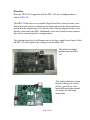
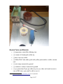
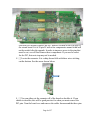
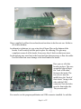
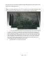
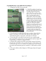
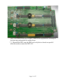
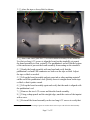
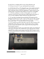
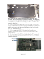
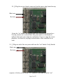
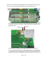
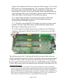
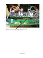
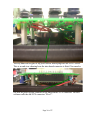
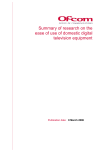
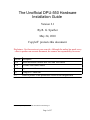
The Unofficial DPU-550 Hardware
Installation Guide
Version 2.1
By R. G. Sparber
May 24, 2010
Copyleft1 protects this document.
Disclaimer: Use these notes at your own risk. Although the author has made every
effort to produce an accurate document, he assumes no responsibility for errors.
Version description
1.0.0
Initial installation without new Flex and Tach cables
1.1.0
Flex and Tach cables added
1.1.1
Typos corrected
2.0
Changed to “unofficial”
2.1
Added a picture of the production version of the daughtercard
1 You may freely distribute this document but not change it.
Page 1 of 27
Table of Contents
Overview...................................................................................................................................3
Scope.........................................................................................................................................4
Needed Tools and Materials......................................................................................................5
Preparing the DRO-350.............................................................................................................6
Final Assembly of the DPU-550.............................................................................................10
Final Modifications to the DRO-350 Circuit Board ...............................................................13
Final Fit to Enclosure..............................................................................................................16
Pictures of the Assembled Unit...............................................................................................24
Acknowledgments...................................................................................................................27
Page 2 of 27
Overview
When the DRO-350 is upgraded with the DPU-550, the resulting machine is
called a DRO-550.
The DRO-350 has been a very capable Digital Read Out system for many years.
During this time processor technology has improved and scale data formats have
grown from the original one to five at last count. Only the original format can be
directly connected to the DRO. Additionally, users have asked for more features
than can be crammed into the existing memory.
The solution chosen by Scott Shumate was to develop a small circuit board, called
the DPU-550, that replaces the exiting processor called a PIC.
This is the board that I
installed onto my DRO350.
This is the production version.
Besides it being a far clearer
picture, you will see a few
minor differences that should
not change the following
instructions.
Page 3 of 27
Some assembly might be required but only of through hole connectors. The Lite
DPU-550 uses the same circuit board as the full DPU-550 but has fewer functions
available.
This document is long. Before you give up right now, understand that I have
shown every step in detail and used lots of pictures. The work will go fast, unless,
of course, you screw up as bad as I did on removing the PIC. Ah, but I get ahead
of myself.
The majority of the connections between DRO and DPU are through the old PIC
connector. If you have bought the full DPU-550, additional cable connections
will be required for power, scales, electronic edge finders, and tachometers. The
Lite DPU-550 sports one extra electronic edge finder port in addition to the
tachometer port on the main circuit board. It is powered from the existing PIC
socket.
Scope
These instructions will lead you through the steps needed to install the DPU-550
into the DRO-350. Once this task is complete, you can turn to the companion
article on how to install the latest software. This will require a Personal Computer,
access to the Internet, and a USB cable.
Page 4 of 27
Needed Tools and Materials
• [ ] temperature controlled soldering iron
• [ ] a means of cleaning the solder tip
• [ ] thin, rosin core solder
• [ ] Solder-Wick2 (the white spool with yellow print) and/or a solder vacuum
tool
• [ ] wrist strap connected to ground
• [ ] conductive surface connected to ground
• [ ] eye protection (If you get solder in your eyes, there isn't much reason to
own a DRO since you won't be able to see it.)
2 See http://en.wikipedia.org/wiki/Solder_wick for an explaination
Page 5 of 27
• [ ] a pair of small diagonal cutters
• [ ] a pair of small needle nose pliers
• [ ] a small Phillips head screwdriver to fit the 4 screws on the back of the
DRO case
• [ ] a medium Phillips head screwdriver to fit the 6 screws holding the main
circuit board in place
• [ ] a small cup to hold loose screws
• [ ] 1 square inch of double sided foam tape
• [ ] two hard rubber washer (see text on page 14 for details)
• [ ] 1” by 2” piece of masking tape or Avery label
• [ ] a thin pointed instrument able to dent the tape or label material
• [ ] a sharp pencil
• [ ] some form of ink that can stay wet for at least 10 seconds (see page 17
for details)
• [ ] two 6-32 screws at least 3/4” long
• [ ] a 1” long straight edge
• [ ] power cable with connectors (full DPU-550 version only)
• [ ] ohm meter or continuity checker
• [ ] additional cables and connectors depending on which version of the
DPU-550 you own plus if you want to use any of the extra inputs
Preparing the DRO-350
By far, this is the most difficult step, especially if done wrong. We must remove
the existing 28 pin PIC from the circuit board without causing damage to the
circuit board. Understand that we should care about the circuit board and not the
PIC. This means we will destroy the PIC in the process but leave the board ready
to accept the DPU.
Are you tired or in a hurry? Then walk away at this point. It only takes a few
seconds to cause lots of damage3
When you are in the proper frame of mind, lets proceed. The box at the end of
3 Do as I say, not as I did. In my haste I used the wrong tool, a Dremel, and sliced half way through the board. I
was able to repair the damage but it took many hours. Luckily, I did not lose a finger.
Page 6 of 27
each step can be checked if you like:
1. [ ] Remove all cables from the DRO.
2. [ ] Using a small Phillips head screwdriver remove the four screws on the
back of the DRO enclosure and place them in the cup.
3. [ ] Pull off the larger part of the enclosure.
Here is the DRO with the top of the case removed.
The tiny red LEDs across the top of the display ICs stick out a little and can easily
be bent. I suggest if you do bend them, do not straighten the leads until you are
done with the upgrade. Repeated straightening of the leads can cause them to
break. Better yet, tape a piece of thick cardboard over the display so the LEDs
don't touch the table when the circuit board is face down.
4. [ ] Put on your grounded wrist strap.4
5. [ ] Remove the four Phillips head screws with the medium size screwdriver
and put them in the cup.
6. [ ] Disconnect all cables.
7. [ ] Turn the circuit board over.
4 Some people treat the wearing of a grounded wrist strap as if it was a religion that can be embraced or rejected.
A lot does depend on humidity levels, but I can tell you that you may destroy circuits on the DRO and DPU yet
never feel a thing. You may also weaken components that will fail in 6 months. Why take the risk?
Page 7 of 27
Our task is to carefully remove the PIC which is located on the left edge of
the circuit board. It is a 28 pin IC with a few components around it that will
not be needed after the upgrade. In order to improve access to the pins that
must be cut, we will first remove these components. If you used a socket
for the PIC, this next step may not be needed.
8. [ ] Locate the resonator. It is a shiny brown blob with three wires sticking
out the bottom. See the arrow shown below.
9. [ ] You can either cut the resonator off of the board or desolder it. If you
choose to desolder, this will be good practice for when you must remove the
PIC pins. Turn the board over and remove the solder from around the three pins
Page 8 of 27
associated with the resonator. This is where the Solder Wick really pays for
itself. Alternately, a solder vacuum can be equally effective. Leave the
soldering iron on the board for as short a time as possible. Excessive heat will
cause traces on the circuit board to lift. If you are unable to remove all of the
solder, add fresh solder and then briefly heat the area and use the Solder Wick
again. As the Solder Wick fills with solder, cut off the end to expose clean
braid. The hole should be free of solder. Well almost. You can expect a tiny
amount of solder between the lead and the hole. Again apply heat and using the
pliers or a probe, move the lead away from the sides of the hole to free it. Do
this for all three pins. The resonator should drop out. It will not be needed in
the upgraded system.
10. [ ] If you used a socket for the PIC, it will be easier to accomplish the next
few steps. You should carefully pull out the PIC and set it aside in a block of
conductive foam to protect it from static discharges. Put on those safety glasses
because bits of plastic may soon be flying. Use the diagonal clippers to cut the
plastic body off of the socket to expose the pins. Skip over the next step.
11.[ ] If you did not use a socket for the PIC, we will now have to cut it out. I
don't have any pictures for this next step because, sadly, I didn't do the PIC
removal this way. I strongly suggest that you don't use my approach because
the damage was extensive. I used a Dremel® with cut off wheel to cut the leads
off of the IC. It sure was quick, but the subsequent damage to the circuit board
took me days to fix. Instead, take your diagonal clippers and cut one of the
leads at the end of the PIC on the side that had the resonator. When you have
cut the first lead, move over and cut the next one. Nibble your way down the
row. You can then bend the PIC up so the leads on the other side are exposed.
Again, start at one end and nibble your way to the other. Toss the dead PIC.
12. [ ] Remove the pin stubs from the board. You can do this with your pliers
on the front side holding a single pin. Apply heat to the circuit board land
around the pin on the back side and pull the pin out. Once all pins have been
removed, bring out your Solder Wick and carefully heat each land and draw
out the solder. Inspect each hole to be sure it is absolutely free of solder. If you
find any solder, fill the hole with fresh solder and again use the Solder Wick to
get it all out. You will be installing new pins in these holes and it is a very tight
fit. The smallest amount of solder will prevent the pins from entering.
13. [ ] Place the DRO-350 board aside in a safe place. It is time to finish
assembling the DPU-550.
Page 9 of 27
Final Assembly of the DPU-550
If you are installing the Lite version of the DPU-550, just skim over the next
few steps. You only need to install the inter-board pins, the Edge 1 connector,
the program pushbutton, and the USB connector.
1. [ ] As you look a the DPU-550, you may find Surface Mount Technology
components5 locations without components. Don't panic. You are not
missing parts and you will not be soldering any of these tiny components in
place.
2. [ ] We will be soldering various connector headers in place. Along with the
DPU-550 you should have a bag holding a variety of pin header sizes. On
profile, they look like little chairs with the legs going all the way through
the seat and out the top.
I am using false colors here so you can see the parts. The body is white plastic
but I show it in green here. The pins are shown in black.
3. [ ] Looking at the circuit board of the DPU, notice that there are many
locations with white ink around groups of at least 2 holes. The white ink
pattern looks like this
except... it is white and not green. If this throws you, maybe it is time to take a
break or at least put down that Scotch. Anyway, the small square shows you
the orientation of the “chair back”. These connectors feed in from the top of
the board.
4. [ ] These pin headers are a loose fit to the holes so you will need some trick to
hold the header in place as you solder. I used a hemostat to grab the end pin as I
soldered the opposite end pin. Once soldered, the hemostat was removed. If
necessary, heat can be reapplied to push the header flat on the circuit board.
5 See http://en.wikipedia.org/wiki/Surface-mount_technology
Page 10 of 27
I have completely soldered in one header and am about to do the next one. Solder in
all of these headers.
An alternative technique is to use a tiny dot of Super Glue on the bottom of the
header. It will securely hold the part in place for soldering. The glue may
complicate removal of the header if necessary later. I don't see that as an issue.
Avoid applying any more heat to the board and pins than necessary to flow the solder.
Excessive heat can cause damage to the board and to the header.
Here you see all of the
headers in place. The ones
around the edge all have
the “back of the chair”
facing to the inside. The
two you see near the
middle have the “back of
their chairs” facing to the
side with the USB
connector. Note the holes
near the front right side.
They are not used.
You can also see the program pushbutton and USB connector installed. As with the
Page 11 of 27
pin connectors, be sure that the pushbutton and USB connector are flat on the circuit
board before soldering all pins.
Inspect all solder connections and re-flow any that are not smooth and limited to the
area around the pin. There must not be any solder bridges to adjacent paths.
5. [ ] The two female pin headers feed in from the back of the circuit board. It
is an easy fit. Solder one end pin first and check that the header alignment. It
must be squarely on surface. Re-flow the solder around the pin if you need to
make an adjustment. Then solder the pin on the other end of header and again
check alignment. Only then should you solder the rest of the pins. Note that
these are the only components that feed in from the back side of the circuit
board. Repeat for the second female pin header.
6.
[ ] Put the DPU-550 circuit board aside.
Page 12 of 27
Final Modifications to the DRO-350 Circuit Board
1. [ ] Bring back the DRO-350 circuit board.
2. [ ] The PIC pin blocks feed in from
the front side of the board. The pins
are square and will cut into the
sides of the holes. As long as all
holes are free of solder, you will be
able to carefully push each pin
block in place. Take care to push
straight in so no pins are bent. The
ends are sharp so you may find that
the pliers help. An alternate method
is to use a small block of wood as a
pusher. If a single pin is tighter
than the rest, you may start to see it
pushing out of the pin block. Not to
worry, you can use your pliers to
push it back in place after the block
is seated on the circuit board. Be
sure the pin blocks are flush against
the circuit board.
3. [ ] Turn the board over and again solder just one end pin. Inspect that the
header is still square on the board, then solder the other end pin. Once
satisfied that the header is still square, solder the rest of the pins.
4. [ ] Trial fit the DPU to the DRO circuit board. Be sure to push straight
down on the DPU so the female pin connector blocks squarely engage with
the pin headers. It should be a snug and solid fit.
5. [ ] With the DPU parallel to the DRO circuit boards, measure the distance
from the back of the DPU to the top of the ICs below it. This distance will
be effected by how the ICs are attached to the DRO circuit board. I did not
use sockets and I found the gap to be around 0.25”. With sockets it will be
less.
6. [ ] We need to add two rubber bumpers to fill this gap and provide support
for the DPU.
Page 13 of 27
I started by putting down two pads of double sided foam tape. Then I found
some used rubber washers out of an old faucet (What? Me throw anything
away!). I thinned them on my belt sander taking care not to thin my finger.
Page 14 of 27
Once I was satisfied that they fit right, I removed the top protective covering on
the foam tape and pushed the washers down.
7. [ ] Reinstall the DPU onto the DRO and verify the two boards are parallel
when the washers contact the DPU-550.
Page 15 of 27
Final Fit to Enclosure
There are two components on the DPU-550 that must pass through openings in
the enclosure. One is the program pushbutton and the other is the USB connector.
1. [ ] Pick up the back of the enclosure which has the connectors mounted to
it and move all cables out of the way.
Page 16 of 27
2. [ ] place the tape or Avery label as shown.
3. [ ] trial fit the DRO plus DPU-550 circuit board assembly on its standoffs.
Use the two long 6-32 screws to align the board on the standoffs yet permit
the board assembly to float vertically. The pushbutton's rod will hit the bottom
of the enclosure to prevent the board assembly from seating on the standoffs.
4. [ ] Steady the board assembly with one hand and verify that the
pushbutton's rod and USB connector are both over the tape or label. Adjust
the tape or label as needed.
5. [ ] Lift up the board assembly and put some ink or other marking material6
on the end of the pushbutton's rod. Quickly lower it straight down on the tape
or label so that it prints a mark.
6. [ ] Lift up the board assembly again and verify that the mark is aligned with
the pushbutton's rod.
7. [ ] Remove the two 6-32 screws and then the board assembly.
8. [ ] Using a sharp pencil and the straight edge, mark the center of the imprint
with a cross.
9. [ ] Re-install the board assembly on the two long 6-32 screws to verify that
6 You might want to try a thin coating of grease or Vaseline but be sure to wipe it all off before final assembly.
Page 17 of 27
the pencil lines are aligned with the center of the pushbutton's rod.
10. [ ] Remove the two 6-32 screws and then the board assembly.
11. [ ] Drill a hole 9/64” or 5/32” through the case at the marked out location
that just passes the tip of the pushbutton's rod. The goal is to have the hole
large enough that it does not bind the pushbutton yet small enough so it does
not flop around. Trial fit the board assembly to be sure there is no binding.
12. [ ] With the pushbutton's rod able to fit through the case, the USB
connector can now press down on the tape or label. Again use the long 6-32
screws to insure alignment without causing the DRO board to bend.
13. [ ] I was able to reach into the area around the USB connector with a
dental pick and mark out all 4 sides. If you can only reach two sides, measure
the USB connector to know where to place the rest of the lines. You should
have a square about 1/2” on a side marked on the tape or label.
14. [ ] It is possible to just drill a large hole to pass the USB-B connector7 but
I didn't think of this until it was too late. The hole must be large enough to
pass this connector but should be small enough to block the passage of the
board mounted connector.
I chain drilled and filed in order to get a square hole. It took a few minutes but
came out nice. The down side is that the face of the USB connector mounted
on the DPU has nothing to push against as I pull the USB-B connector out of
it. This has turned out not to be a problem. No matter how you choose to do it,
cut the opening.
7 See http://en.wikipedia.org/wiki/USB#Types_of_USB_connector
Page 18 of 27
Here you see the USB connector peaking through the back of the DRO
enclosure. The probe is pointing to the program pushbutton. You can also see
my separate electronic edge finder and tachometer jacks in the upper left hand
corner. I chose to not add connectors for Edge 2 or Flex 1 at this time. Flex 1
used to be called Tach 1.
15. [ ] If you bought the Lite DPU-550 version, then put the existing cables
back on the DRO-350 board in their original position. If desired, install a new
jack for the electronic edge finder input and plug into Edge 1 socket on the
DPU-550. Then skip to step 24.
16. [ ] If you bought the full DPU-550 version, then locate the power
connector attached to the enclosure. Trace the wires and find the two pin
female connector.
17. [ ] Look at the end of the DPU board furthest from the PIC connector. At
the corner you will see one connector marked “out”. Next to it is an identical
connector marked “in”.
“out”
“in”
Page 19 of 27
18. [ ] Plug the two-pin female connector from the power plug located in step
Black wire
Red wire
16 into the “in” header. The red and black wires should be as shown above.
You may want to use a red and black fine point marker on the header to
indicate what color wires connects to which pin. If you are using the correct
plug here, it will not let you plug it in backwards so this would not be an
issue.
19. [ ] Plug one end of the new power cable into the “out” header. Verify that the
Black wire
Red wire
sequence of colors you see on the “in” connector is the same as on the “out”
Page 20 of 27
connector. You should see the red and black wires as shown above. If these wires
are reversed, you may blow up the DRO so be sure to check this twice.
20. [ ] Plug the other end of the new power cable into the power connector on
the DRO board shown circled above. With the DRO power connector in the
upper right corner,
Red wire
Black wire
you should have the red wire on the right and the black wire on the left.
21. [ ] As a final test that the power cables are not switched, verify that there
is continuity between a ground point on the DRO circuit board and the DPU
circuit board. One place to find ground on the DRO board is at the center hole
Page 21 of 27
of where the resonator was before you removed it back on page 8. Over on the
DPU board, you can find ground at the “out” connector's left pin. This is the
pin closest to the corner of the DPU board. You should see a dead short
between these two points. If your meter initially shows it shorted but then an
open, this implies that you are seeing filter capacitors which would mean one
of the cable ends is on backwards. Fix this before moving on.
22. [ ] Again using your meter, verify that you do not have a dead short
between power and ground. You can access these nodes at the power
connector bolted to the DRO enclosure.
23. [ ] The full version of the DPU-550 enables you to have two more scales,
two more electronic edge finder inputs, another tachometer input, and an
RS232 port8. Connect these as you see fit.
24. [ ] If you choose to install a piezo beeper, connect it to one of the Flex
connectors. They may be labeled Tach or AUX. I used the one on the DRO
circuit board.
The red wires goes to the +5 volt pin and the black wire goes to the center pin
which is normally the input. The software will pull this center pin down to ground
to make the beeper sound. You may need to put a large resistor across the piezo
beeper to quiet it when not turned on. There is a small leakage current at all times.
I used a 10K resistor. Just be sure that the total current flow is less than 8 mA. See
8 The RS-232 connection on the DPU-550 is primarily intended for software development
since it's where all of the pretty debug messages go but it's perfectly usable for programming
and PC automation. It is not include on the Lite board because most people will probably
prefer the USB. The RS-232 only uses three connections - transmit, receive, and ground. The
DB-9 connector is wired to the DPU-550 by connecting pins 2 & 3 to the Tx and Rx ports,
respectively, on the RS-232 header. Pin 7 on the DB-9 is wired to ground.
Page 22 of 27
page 26 for a picture of the installed piezo beeper.
25. [ ] Carefully reassemble the board assembly on the standoffs using the
original short 6-32 screws. Do not force anything. I had some trouble with
wires getting caught between a DPU feature and a DIN connector. It will all
fit with the wires out of the way. I took the time to route the scale wires away
from the display area as the proximity might cause an increase in noise pick
up that can cause scales to jitter.
26. [ ] Inspect the small red LEDs above the display area and straighten them
as needed.
27. [ ] Re-fit the enclosure verifying that the LEDs fit in their holes.
28. [ ] Using the four small screws, secure the enclosure
29. [ ] Congratulations! You are now ready to install the software.
Page 23 of 27
Pictures of the Assembled Unit
You can see the DPU-550 buried in there with many wires attached.
Page 24 of 27
Note one of the two washers supporting the DPU-550
Page 25 of 27
Directly under the keypad is my piezo buzzer which plugs into the Flex 2 socket.
This is an end view showing how the inter-board connector is fitted. You can also
see how the piezo beeper connects to the main board's AUX connector. The new
software calls the old AUX connector “Flex 2”.
Page 26 of 27
Acknowledgments
My thanks go out to J. Eric "jet" Townsend, Larry Gill, and Jim Fager for their
insightful suggestions for making this document better. Thanks to Greg
[[email protected]] for supplying the picture of the production DPU-550.
Page 27 of 27