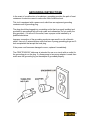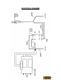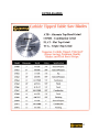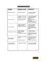
1
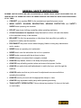
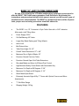
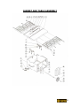
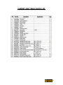
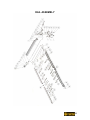
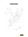
OWNER’S MANUAL B2397 LEFT TILTING 10” CONTRACTOR’S TABLE SAW TABLE OF CONTENTS GENERAL SAFETY INSTRUCTIONS Page 3 Features Shipping Carton Contents Base Assembly Saw Assembly Align-A-Rip Fence Assembly Aligning the Align-A-Rip Fence Final Assembly Final Assembly Continued Replacing the Saw Blade Operation Instructions Page 4 Page 5 Page 6 Page 7 Page 8 Page 9 Page 10 Page 11 Page 12 Page 13 Table Saw Tips Making a Push Stick Avoiding Kick-Back Basic Cutting Techniques Ripping Bevel Ripping, Ripping Small Pieces, Cross Cutting Bevel Cross Cutting, Mitering, Compound Mitering Page 14 Page 15 Page 16 Page 17 Page 18 Maintenance Grounding Extension Cord Use & Voltage Information Electrical Diagram Extra Blades Troubleshooting Page 19 Page 20 Page 21 Page 22 Page 23 Page 24 Schematics & Part Listings Machine Diagram & Parts List Cabinet & Table Assembly Cabinet & Table Parts List Rail Assembly Rail Assembly Parts List Stand Assembly & Parts List Trunnion Assembly Trunnion Assembly Parts List Elevation Mechanism Assembly & Parts List Miter Gauge Assembly & Parts List Spreader Assembly & Parts List Motor Assembly & Parts List Page 25 Page 26 Page 27 Page 28 Page 29 Page 30 Page 31 Page 32 Page 33 Page 34 Page 35 Page 36 Warranty Information Page 37 2 GENERAL SAFETY INSTRUCTIONS EXTREME CAUTION SHOULD BE USED IN OPERATING ALL POWER TOOLS. KNOW YOUR POWER TOOL, BE FAMILIAR WITH ITS OPERATION. READ THE OWNER’S MANUAL AND PRACTICE SAFE USAGE PROCEDURES AT ALL TIMES. CONNECT your machine ONLY to the matched and specified power source. WEAR SAFETY GLASSES, RESPIRATORS, HEARING PROTECTION and SAFETY SHOES when operating this machine. DO NOT wear loose clothing or jewellery when operating machinery. A Safe Environment is important. Keep the area free of dust, dirt and other debris in the immediate vicinity of the machine. BE ALERT! Do Not Use prescription or other drugs that may affect your ability or judgement to safely use this machine. DISCONNECT the power source when changing, blades or doing any maintenance and or repairs. NEVER leave an operating tool unattended. NEVER reach over the table when the tool is in operation. NEVER make crosscuts with the rip fence in place. NEVER attempt cut material that is warped or twisted. ALWAYS keep blades, knives or bits sharp and properly aligned. ALWAYS keep all safety guards in place and ensure their proper function. ALWAYS use push sticks and featherboards to safely feed your work through the machine. ALWAYS make sure that any tools used for adjustments are removed before operating the machine. ALWAYS secure your work with the appropriate clamps or vises. ALWAYS keep bystanders safely away while operating machinery. THINK SAFETY. WORK SAFELY. Never attempt a procedure if it does not feel safe or comfortable. 3 B2397 10” LEFT TILTING TABLE SAW As part of the growing line of Craftex woodworking equipment, we are proud to offer the B2397. The Craftex name guarantees Craft Excellence. By following the instructions and procedures laid out in this owner’s manual, you will receive years of excellent service and satisfaction. The B2397 is a professional tool and like all power tools, proper care and safety procedures should be adhered to. FEATURES The B2397 is a 10” Contractor’s Style Table Saw with a 2HP Induction Motor and a Left-Tilting Arbor. Power Supply: 220V Full Ball Bearing 5/8” Arbor. Large Alloy Blade Raising and Tilting Wheels. Arbor Lock. Belt-Driven Arbor. Table Saw Height: 36 1/2” Overall Table Dimensions: 27” x 48”. Maximum Rip to Right of Blade: 30”. Precision Ground Cast-Iron Table. Precision Ground Open Grid Table Extensions. Shrouded Blade and Arbor for Efficient Dust Control. High-Mounted Safety Power Switch with Removable Key. Maximum Cut Depth at 90 Degrees: 3 3/8”. Maximum Cut Depth at 45 Degrees: 2 1/2”. Sheet Metal Open Stand. Extremely Accurate Align-A-Rip ‘T’ Fence with Optical Cursors and MicroAdjustments. ‘T’ Slot Miter Gauge. Shipping Weight 120 kg. 4 CARTON CONTENTS Check to see that all of these components are in your carton. Your B2397 Left Tilting Table Saw carton contains all of the components necessary to provide you with years of quality service, including a quality carbide tipped blade. The individual components will be explained later in this Owners Manual. Base Parts Misc. Components, Details in Manual Fence Rails & Power Switch Connectors Table Extensions Table Extension Fence Rail Support Blade Elevation Lock Allen Wrenches Hex Bolts & Lock Washers for Extentions 5 BASE ASSEMBLY Remove all Sheet Metal Components from the box and set aside. Remove the large plastic bag containing miscellaneous small parts and remove the small bag containing the zinc plated nuts, washers and bolts. Select the round head carriage bolts, washers and nuts. The shorter stretchers are for the top support of the base and have dents to fit them to the legs. Use 1 carriage bolt, 1 washer and 1 nut in each of the square holes that match the leg and stretcher. Do not tighten the nuts at this time. Set the base on a level floor and using a spirit level, make sure that the top surfaces of the steel base are level, commence tightening of the base nuts. Select the black washers and nuts for use with the adjustable leveller feet and install them on the base legs. Install 1 nut on the foot before inserting it in the leg. Install a washer and the second nut but hand tighten only. Use a spirit level; adjust all base feet by raising or lowering the bottom nut on the leg until the base assembly is sitting level. Tighten the top nut down to secure the base legs. You will be left with 4 zinc plated bolts, 8 washers and 4 hex nuts. Set these aside for mounting the table-saw to the base. 6 B2397 SAW ASSEMBLY Remove cast-iron saw table extensions from the carton and set aside. Remove the table saw from the carton and discard all packing materials from the cavity of the saw. Un-wrap the power cord and power switch assembly. Clean all cast-iron parts with mineral spirits to remove the protective coating. Thoroughly dry and apply a coat of paste wax and polish. Carefully mount the saw on the assembled base using the 4 zinc plated bolts, 8 washers and 4 nuts. The Craftex label on the base should be facing the front of the saw. The power cord and on/off switch should be fed down through the top of the base to be attached to the ripfence rail later. Assemble the two cast-iron extension tables using the 8 bolts and lock washers illustrated. The cast-iron extension tables have holes in the end edges to accept hangers for the rip-fence front and rear rail assemblies. Select the 4 large tapered-head philipsdrive machine screws, 4 washers and 4 nuts and attach the hangers. DO NOT TIGHTEN AT THIS TIME. Select the 2 hand-wheels from the parts container, one is for the saw blade elevation and one is for the blade bevel adjustment. The blade elevation wheel is fitted with a shaft bearing and a height lock. Install the bearing, handwheel, lock knob, washer and bolt to the axle and tighten the bolt. Install the blade bevel hand-wheel using a machine screw found in the parts bag. A separate lock for the bevel angle will be found already installed above the blade elevation wheel. 7 B2397 ALIGN-A-RIP FENCE ASSEMBLY Your CRAFTEX Table Saw is equipped with the precision Align-A-Rip fence and when assembled, will provide you with years of precise cutting. There are 5 basic components to the fence assembly, 2 front rail halves, 2 rear rail halves and the rip fence itself. Select the 2 front halves with the measurement scale on them. From the parts bag, select the square-head bolts, washers and nuts. You will find a channel in the extrusion of the fence into which these bolts will slide. Slide 3 of these bolts into the right side portion of the front fence and position them so that they will fit into the holes in the front edge of the saw table. One of the bolts will fit into the hanger strap. Install a washer and nut and leave loose. Repeat the procedure with the left side front fence extrusion. Slide the two halves together so that the plastic sleeve makes a snug fit. Repeat the above procedure for the rear fence rails and you may handtighten all of the nuts at this point. Using the smaller machine bolts and nuts, install the power switch as pictured on the front fence rail and tighten. Install the auxiliary fence support/tool shelf on the extreme right end of both front and rear rails using the remaining 4 square-head bolts, washers and nuts. Install the Align-A-Rip fence by placing the front of it on the front rail and pushing down on the back portion to engage in the rear rail. The rails should still be loose at this point so some jiggling may be required. 8 ALIGNING THE ALIGN-A-RIP FENCE The Align-A-Rip fence should now be aligned and this is best done before further assembly, however, a 10” saw blade should now be installed. Select the type of saw blade that you will be using on a continual basis. (Disconnect the machine from the power source) Loosen the screw on the table insert with a phillips screwdriver and set the insert to one side. Your CRAFTEX table saw comes complete with 2 doubleended blade wrenches. One end is for the arbor nut while the other fits over the arbor and engages in slots that will lock the arbor. Raise the saw arbor to its highest point Engage the arbor lock and using the wrench, remove the blade bolt and washer. Install the blade, the washer (with the flat side facing the saw blade) and arbor nut and tighten. DO NOT OVER-TIGHTEN. Replace the saw table blade insert a make the screw only snug and sitting just below the surface. Set the saw bevel to ‘0’ so that the blade is vertical and lock the bevel with the lever above the blade height wheel. Raise the blade. Slide the Align-A-Rip fence over to the right of the saw blade and check the fence cursor to the left of the fence. The cursor line should be at the ‘0’ mark or first line of the right side of the scale. To adjust the front fence rail use a rubber mallet to ‘tap’ the rail assembly either left or right until this is attained. The rear fence rail should be similarly adjusted. When the fence is tight to the saw blade and the left cursor is at ‘0’, the rear fence should be “squared” with the front fence. Lock the fence down by pushing down on the fence-locking lever. Now you may tighten all of the nuts supporting the front and rear fence rails including the auxiliary support/tool shelf. Tighten the machine screws and nuts on the hangers as well. 9 B2397 FINAL ASSEMBLY AND FINE TUNING Select the 4 plastic fence rail end caps and 4 self-tapping screws and install at the ends of the Align-A-Rip fence rails. Select the 90 degree sawdust port and install it under the saw table. This fitting ‘snaps’ into place and then will rotate freely when connected to a sawdust collector. Lower the saw blade to its lowest position and remove the saw table blade insert by loosening the front screw. Loosen the 2 bolts through the metal plates at the rear of the opening and attach the saw blade guard, pawls and kerf splitter. The slots on the rear plate of the splitter will fit over the bolts. There are 3 positions for it to fit. Raise the saw blade slightly so that it is about an inch above the table surface. Use a straightedge to align the blade with the splitter to ascertain the correct position. Tighten the bolts securely. Thoroughly clean the ‘T’ miter slots to remove any grease and insert the miter gauge. This is best achieved by having the tail of the gauge slightly beyond the rear of the saw table and then drawing it back. There are three positive stops on the miter gauge that have been pre-set at the factory, 0 degrees, 45 degrees left and 45 degrees right. Any further adjustments may be done with an allen wrench by loosening or tightening the screws under the gauge. The saw table insert has four adjustable levelling screws to ensure that it sits flush with the tabletop and to prevent any possible wobble. They are accessible from the top of the insert and may be adjusted with an allen wrench. Your CRAFTEX B2397 table saw is a precision tool with versatility. Your Align-ARip fence may be used to the left or right of the saw blade by either lifting it off the rails or lowering the saw blade and simply sliding it over to the left or right side of the saw blade. The Align-A-Rip fence has ‘T’ slots on the faces that will allow you to add a sacrificial auxiliary rip fence. You must however, compensate for the thickness of this added fence when using the cursor. 10 FINAL ASSEMBLY AND FINE TUNING CONTINUED There is a yellow plastic insert in the saw table top and this is used for making a pencil line to indicate the cut-line of the particular saw blade that you have installed in the saw. The on/off switch has a removable key to prevent unauthorized persons from using it. The yellow portion of the switch may be pulled out and stored in a safe place when the tool is in the off position. 11 REPLACING THE SAW BLADE 1. Disconnect the machine from the power source 2. Turn the saw blade raising the hand wheel to raise the blade approximately 20mm (0.79”) above the table surface 3. Remove the throat plate by loosening the cross-head screw at the front of the plate and lifting the plate out. 4. Place one blade wrench onto the flats of the blade arbor. Place the other wrench onto the arbor nut. Remove the arbor nut and flange from the saw arbor by turning counter-clockwise. Move the saw blade to the highest position and remove it. 5. Ensure that the spindle and washer are clean of dust and debris. Place the new saw blade onto the spindle and make sure the blade teeth point down towards the front of the table. Put the washer and arbor nut on the spindle and tighten the arbor nut as much as possible by hand. Make sure that the new saw blade is against the inner flange and the large washer diameter is against the blade. 6. Lower the blade and place one blade wrench onto the flats on the blade arbor. Place the other blade wrench onto the arbor nut. Tighten the arbor nut by turning it clockwise. 7. Different saw blades will make different sizes of kerf. Check the adjustment of the rip fence pointer and the blade guard splitter after changing blades. 12 OPERATION INSTRUCTIONS The two basic kinds of cuts on a table saw are cross cutting and ripping. In general, cutting with the grain is ripping and cutting against the grain is cross cutting. However, with composite materials this distinction may be difficult to make, or not apply at all. In these cases, cutting the wood lengthwise is ripping and across the shorter dimension is cross cutting. Do not perform either operation freehand. Use the fence for ripping and the mitre gauge for cross cutting. Before using your saw, check the following (with power disconnected): 1. Make sure the blade is tight and secure 2. Bevel angle and height lock knobs are tight 3. If ripping, make sure the fence lock lever is tight and the fence is parallel to the blade. 4. If cross cutting, make sure the mitre gauge is tight. 5. Make sure safety glasses/goggles are worn at all times. 6. Make sure the blade is properly ground and attached and that the anti-kickback pawls are functioning. Failure to check these points may result in serious injury 13 MAKING A PUSH STICK In order to operate your table saw safely, you must use a push stick whenever the size or shape of the work piece will cause your hands to be within 6” of the saw blade. Make sure the push stick is long and sturdy enough to apply a noticeable amount of pressure. A length of 14” is recommended with a notch that fits against the edge of the work piece to prevent slipping. It is a good idea to have several push sticks of the same length (14”) with different sized notches for work pieces of different thickness. Below is a sample pattern of a typical push stick. The shape will vary depending on your needs/requirements. The main purpose of the push stick is to keep your hands away from the blade. Making the push stick out of hardwood or plywood is ideal. Ensure that it is less than or equal to the width of the work piece to be cut. 14 KICKBACK – HOW TO AVOID IT AND PROTECT YOURSELF The dangers of kickback cannot be overstated. Most often it is caused by the work peice binding against the blade. The result is that the work piece can rapidly move in a direction opposite to the feed direction. During kickback, the work piece can be thrown back towards the operator and can be very dangerous. It can also drag the operator’s hand towards the blade if the operator’s hand is in the wrong place. To prevent kickback, please try and follow these guidelines and remember, one can never be too safe. 1. Always use the guard, and continue to check that it is in in good working order. The guard’s splitter helps prevent binding and the anti-kickback pawls on each side of the splitter minimize the possibility of kickback. . 2. Do not saw warped, bowed or cupped wood. The work piece should have one straight smooth side to go against the rip fence or mitre gauge. 3. Do not cut “freehand”. Always use either the rip fence or the mitre gauge. Never use both. 4. Use extra care when the guard assembly cannot be used. (During dadoing) 5. Support large pieces carefully. Allowing them to sag or drop can be dangerous. 6. Make sure the rip fence is parallel to the saw blade. 7. Use a push stick for short pieces. Plastic and composite materials such as hardboard can be cut on this table saw. However, as you know these materials are hard and usually slippery and the anti-kickback pawls may not prevent kickback in all cases. Therefore, use extra caution in cutting procedure when cutting these types of materials. 15 BASIC CUTTING TECHNIQUES RIPPING 1. Lock the rip fence by pressing the fence lock lever down. Remove the mitre gauge. 2. Raise the blade so that it is about 3.2mm (0.13”) higher than the top of your work piece. 3. Hold the work piece flat on the table against the rip fence. Keep the work piece about 25mm away from the blade 4. Turn the saw on and allow the blade to come up to speed. Both hands can be used in starting the cut. When there is approximately 305mm (12”) left to be ripped, use a push stick to finish the cut to avoid any accidents with your near hand. 5. Keeping the work piece against the table and fence slowly feed the work piece rearward all the way through the saw blade. Continue pushing the work piece until it is clear of the guard and it falls off the rear of the table. Do not overload the motor. 6. NEVER try to pull the work piece back with the blade moving. Turn the power switch off, wait for the blade to stop fully turning, raise the anti-kickback pawls if necessary and slide out the work piece. 7. When sawing materials of great length or panels, always use a work support. A sawhorse, roller or outfeed assembly can provide adequate support for long work pieces. Make sure that the work support is the same height as the table saw. 8. NEVER push or hold onto the “free” or “cut off” portion of the work piece. 16 BASIC CUTTING TECHNIQUES Cont…. BEVEL RIPPING Bevel ripping is performed the same as ripping but with the saw blade set at an angle not perpendicular with the table surface. After changing the bevel angle, check the alignment of the guard and splitter and make sure there is clearance with the saw blade. RIPPING SMALL PIECES Bevel ripping is performed the same way as ripping but with the saw blade set at an angle not perpendicular with the table surface. After changing the bevel angle, check the alignment of the guard and splitter and make sure there is clearance. Any action that brings the operator’s hand near the saw blade are hazardous. When a small width is to ripped , use one or more push sticks to push the work piece past the saw blade. CROSS CUTTING 1. Remove the rip fence and place the miter gauge in the slot on the table surface 2. Adjust the blade height so that the blade is about 3.2mm (0.13”) higher than the top work piece. 3. Hold the work piece firmly against the miter gauge with the path of the blade in line with the desired cut location. Keep the work piece approximately 2.45cm (1”) infront of the blade. Keep both hands away from the blade and out of the cutting line. 4. Start the saw motor and allow the blade to come up to speed. 5. Using both hands to keep the work piece against the face of the mitre gauge and holding the work piece flat on the table, slowly push the work piece through the blade. 6. NEVER try to pull the work piece back while the blade is still turning. Turn the power off and allow the blade to stop fully turning and carefully slide out the work piece. 7. NEVER touch or hold onto the “free” or “cut off” portion of the work piece. 17 BASIC CUTTING TECHNIQUES Cont…. BEVEL CROSS CUTTING This operation is the same as cross cutting except that the bevel angle is set to an angle other that 0°. After changing the bevel angle, check the alignment of the guard and splitter and make sure there is clearance with the saw blade. MITERING This operation is the same as cross cutting, except that the miter gauge is locked to an angle other than 0°. Hold the work piece firmly against the miter gauge and feed the work piece slowly in to the blade to prevent it from moving during the cut. COMPOUND MITERING This is a combination of bevel cross cutting and mitering. It is infrequently used. Follow the instructions for both bevel cross cutting and mitering. 18 MAINTENANCE AND LUBRICATION Proper care and maintenance should be give to your B2397 to ensure a longer life. Use only mild soap and a damp cloth the clean to the tool. Do not allow liquid to enter the machine. Do not immerse any part of the table saw in liquid. Keep the table surface free of rust. If you notice rust spots after some time, treat them immediately. To lubricate the saw, first use a stiff brush to clean any dust and debris from the gears and worms. Remove and pitch or resin that has accumulated. Use a light solvent if necessary. Apply grease to the gears. Paste wax can be used if the grease is attracting too much dust. Keep all spray lubricants away from the upper guard. After long term use, the saw table mechanisms may require lubrication. For maximum safety and reliability, major repairs and maintenance should be performed at an authorized service center. MAINTANING THE RIP FENCE The rip fence should always slide freely. If it requires excessive force to slide it, or if it feels rough, wipe the rails and fence head gliding surface with a cloth. Check the movement again. If it is still rough, clean the fence head with a mild solvent. Coat the rail with a heavy coat of paste wax or a light oil. Slide the fence back and forth several times to coat the rail and fence. Wipe off any excess wax or oil from the rail. If the fence still does not move freely, adjust the fence tension. 19 GROUNDING INSTRUCTIONS In the event of a malfunction or breakdown, grounding provides the path of least resistance for electric current to reduce the risk of electric shock. This tool is equipped with a power cord, which has an equipment-grounding conductor and a grounding plug. The plug should be plugged into a matching outlet that is properly installed and grounded in accordance with all local codes and ordinances. Do not modify the plug provided – if it will not fit the outlet, have a proper outlet installed by a qualified electrician. Improper connection of the grounding conductor can result in a risk of electric shock. Use only 3-wire extension cords that have 3-prong grounding plugs and 3hole receptacles that accept the tools plug. If the power cord becomes damaged or worn, replace it immediately. The CRAFTEX B2397 table saw is intended for use on a circuit with an outlet for the grounding pin on the plug. If a three-prong to two-prong adapter is used, then make sure the grounding lug on the adapter is grounded properly. 20 EXTENSION CORDS If you use an extension cord, make sure that it is in good condition. An extension cord with insufficient capacity will cause a drop in line voltage and lead to a loss of power and overheating. The chart below shows the correct sizes to use depending on cord length and nameplate ampere rating. If in doubt, use the next heavier gauge. The lower the gauge, the heavier the cord. If this saw is to be used outdoors, make sure the extension cord is rated for outdoor use. Do not use damaged or worn cords. 21 ELECRTICAL DIAGRAM 22 EXTRA BLADES 23 TROUBLESHOOTING 24 MACHINE DIAGRAM AND PARTS LIST 25 CABINET AND TABLE ASSEMBLY 26 CABINET AND TABLE PARTS LIST 27 RAIL ASSEMBLY 28 RAIL ASSEMBLY PARTS LIST 29 STAND ASSEMBLY AND PARTS LIST 30 TRUNNION ASSEMBLY 31 TRUNNION ASSEMBLY PARTS LIST 32 ELEVATION MECHANISM ASSEMBLY AND PARTS LIST 33 MITER GAUGE ASSEMBLY AND PARTS LIST 34 SPREADER ASSEMBLY AND PARTS LIST 35 MOTOR ASSEMBLY AND PARTS LIST 36 CRAFTEX 2 YEAR LIMITED WARRANTY Craftex warrants every product to be free from defects in materials and agrees to correct such defects where applicable. This warranty covers two years for parts and 90 days for labour (unless specified otherwise), to the original purchaser from the date of purchase but does not apply to malfunctions arising directly or indirectly from misuse, abuse, improper installation or assembly, negligence, accidents, repairs or alterations or lack of maintenance. Proof of purchase is necessary. All warranty claims are subject to inspection of such products or part thereof and Craftex reserves the right to inspect any returned item before a refund or replacement may be issued. This warranty shall not apply to consumable products such as blades, bits, belts, cutters, chisels, punches etceteras. Craftex shall in no event be liable for injuries, accidental or otherwise, death to persons or damage to property or for incidental contingent, special or consequential damages arising from the use of our products. RETURNS, REPAIRS AND REPLACEMENTS To return, repair, or replace a Craftex product, you must visit the appropraite Busy Bee Tools showroom. Craftex is a brand of equipment that is exclusive to Busy Bee Tools. For replacement parts directly from Busy Bee Tools, for this machine, please call 1-800-461BUSY(2879), and have your credit card and part number handy. • All returned merchandise will be subject to a minimum charge of 15% for re-stocking and handling with the following qualifications. • Returns must be pre-authorized by us in writing. • We do not accept collect shipments. • Items returned for warranty purposes must be insured and shipped pre-paid to the nearest warehouse (see locations on inside back cover of this manual). • Returns must be accompanied with a copy of your original invoice as proof of purchase. Returns must be in an un-used condition and shipped in their original packaging a letter explaining your reason for the return. Incurred shipping and handling charges are not refundable. • Busy Bee will repair or replace the item at our discretion and subject to our inspection. • Repaired or replaced items will be returned to you pre-paid by our choice of carriers. • Busy Bee reserves the right to refuse reimbursement or repairs or replacement if a third party without our prior authorization has carried out repairs to the item. • Repairs made by Busy Bee are warranted for 30 days on parts and labour. • Any unforeseen repair charges will be reported to you for acceptance prior to making the repairs. • The Busy Bee Parts & Service Departments are fully equipped to do repairs on all products purchased from us with the exception of some products that require the return to their authorized repair depots. A Busy Bee representative will provide you with the necessary information to have this done. • For faster service it is advisable to contact the nearest Busy Bee Tools location for parts availability prior to bringing your product in for repairs. For more information, please call toll free 1-800-461-BUSY or visit www.busybeetools.com 37 38 1. 39 40