1
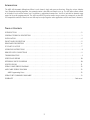
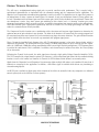
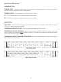
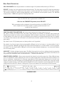
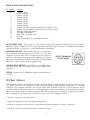
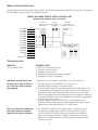
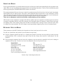
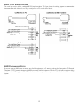
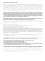
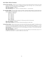
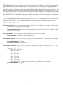
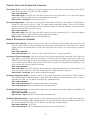
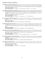
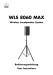
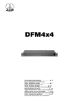
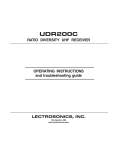
AS8/AS8TC
8 Channel Automatic Matrix Mixer
OPERATING INSTRUCTIONS
and trouble-shooting guide
INTRODUCTION
The AKG AS8 Automatic Microphone Mixer is an 8 channel, single rack space audio mixer. Using the unique Adaptive
Level Proportional mixing algorithm, the automatic action is inaudible and simple to set up. The AS8 offers remote control
of all channel levels and the master level. In addition, a sophisticated compressor/ leveller is included for dynamic range
control of the audio program material. The AS8 has an RS-232 port for remote setup or control by a computer or other RS232 compatible controller. More than one AS8 may be coupled together when applications call for more than 8 channels.
TABLE OF CONTENTS
INTRODUCTION . . . . . . . . . . . . . . . . . . . . . . . . . . . . . . . . . . . . . . . . . . . . . . . . . . . . . . . . . . . . . . . . . . . . . . . . 2
GENERAL TECHNICAL DESCRIPTION . . . . . . . . . . . . . . . . . . . . . . . . . . . . . . . . . . . . . . . . . . . . . . . . . . . . . . . . 3
INSTALLATION . . . . . . . . . . . . . . . . . . . . . . . . . . . . . . . . . . . . . . . . . . . . . . . . . . . . . . . . . . . . . . . . . . . . . . . . . . 4
FRONT PANEL DESCRIPTION . . . . . . . . . . . . . . . . . . . . . . . . . . . . . . . . . . . . . . . . . . . . . . . . . . . . . . . . . . . . . . . 5
REAR PANEL DESCRIPTION . . . . . . . . . . . . . . . . . . . . . . . . . . . . . . . . . . . . . . . . . . . . . . . . . . . . . . . . . . . . . . . . 6
FCC PART 15 NOTICE . . . . . . . . . . . . . . . . . . . . . . . . . . . . . . . . . . . . . . . . . . . . . . . . . . . . . . . . . . . . . . . . . . . . 7
OPERATING INSTRUCTIONS . . . . . . . . . . . . . . . . . . . . . . . . . . . . . . . . . . . . . . . . . . . . . . . . . . . . . . . . . . . . . . . 8
REMOTE LEVEL CONNECTIONS . . . . . . . . . . . . . . . . . . . . . . . . . . . . . . . . . . . . . . . . . . . . . . . . . . . . . . . . . . . . 9
TROUBLESHOOTING . . . . . . . . . . . . . . . . . . . . . . . . . . . . . . . . . . . . . . . . . . . . . . . . . . . . . . . . . . . . . . . . . . . . . 9
SERVICE AND REPAIR
. . . . . . . . . . . . . . . . . . . . . . . . . . . . . . . . . . . . . . . . . . . . . . . . . . . . . . . . . . . . . . . . . . . 10
RETURNING UNITS FOR REPAIR
. . . . . . . . . . . . . . . . . . . . . . . . . . . . . . . . . . . . . . . . . . . . . . . . . . . . . . . . . . . 10
SPECIFICATIONS . . . . . . . . . . . . . . . . . . . . . . . . . . . . . . . . . . . . . . . . . . . . . . . . . . . . . . . . . . . . . . . . . . . . . . . 11
SERIAL CABLE WIRING DIAGRAM . . . . . . . . . . . . . . . . . . . . . . . . . . . . . . . . . . . . . . . . . . . . . . . . . . . . . . . . . . 12
AMX CABLE WIRING DIAGRAM
. . . . . . . . . . . . . . . . . . . . . . . . . . . . . . . . . . . . . . . . . . . . . . . . . . . . . . . . . . . 12
AMX Programming Notes . . . . . . . . . . . . . . . . . . . . . . . . . . . . . . . . . . . . . . . . . . . . . . . . . . . . . . . . . . . . . . . 12
SERIAL PORT COMMANDS AVAILABLE
. . . . . . . . . . . . . . . . . . . . . . . . . . . . . . . . . . . . . . . . . . . . . . . . . . . . . . 13
WARRANTY . . . . . . . . . . . . . . . . . . . . . . . . . . . . . . . . . . . . . . . . . . . . . . . . . . . . . . . . . . . . . . . . . . . . . Back cover
2
GENERAL TECHNICAL DESCRIPTION
The AS8 uses a straightforward analog signal path to provide excellent audio performance. This is coupled with a
sophisticated microcontroller to implement both the automatic mixing and the compressor/leveller algorithms. The
Adaptive Level Proportional automatic mixing algorithm is used by the AS8. This algorithm uses the signal level pattern at
the microphones to derive a pattern of channel gains. For instance, if only one microphone channel is being spoken into,
its level is dominant and that channel gets most of the system gain, while all other channels are turned down. If more than
one microphone is active, they share system gain according to their relative levels. A “skewing” function gives some
advantage to microphones which are active over time, to minimize interruptions from transient noise at other microphones.
Since each channels’ gain is apportioned continuously based on its relative level, no abrupt gain changes are made. This
makes the automatic action virtually inaudible.
The Compressor/Leveller function uses a combination of the short-term and long-term signal dynamics to determine the
optimum amount of gain reduction in any situation. The effect of the function is to control both the average program level
(for consistent long-term sound system level) and to minimize any large short-term deviations. The gain reduction function
is gated, which means that there are no noise ups associated with program signal pauses.
Figure 1 shows the simplified block diagram of the AS8. The microphone preamp is a low-noise discrete design, which is
extensively RF protected. The preamp has three gain settings. The 0dB setting allows an input to accept line level signals,
while the +30dB and +50dB gain settings accommodate both low and high sensitivity microphones. 15V Phantom power
is provided for each channel, and is switchable. In addition, each channel may be switched into either the Direct (always
on) or Auto mode.
Following the Channel Level control, the audio signal passes through a high quality Voltage Controlled Amplifier (VCA).
This VCA, controlled by a signal from the system D/A converter, is used to implement gain control for the automatic mixing
function, as well as the remote level function. A Channel On LED indicates which channels are currently active.
Signals from the Expansion In and Expansion Out connectors allow multiple AS8 mixers to be combined if more than 8
channels are necessary for the application. In addition, a Mix Minus signal is available which allows easy interfacing to
teleconferencing hybrids.
An RS-232 port is available to allow many of the functions of the AS8 to be controlled either by a computer or a dedicated
control system (such as the AMX or Crestron systems).
1 OF 8 INPUT CHANNELS
DIR OUT
DIRECT/AUTO
PHANTOM POWER
+5V
TO uP
+15V
HI
AUDIO
VCA
CHANNEL LEVEL
MIC IN +
Σ
LO
CHAN
ON
MIC
PREAMP
Tone Control
AS8-TC Only
FROM
OTHER
CHANNELS
MIC IN -
MIC GND
PREAMP
GAIN
0 dB (LINE)
+30 dB (MIC)
+50 dB (MIC)
Remote Level CH1
Remote Level CH2
Remote Level CH3
Remote Level CH4
Remote Level CH5
Remote Level CH6
Remote Level CH7
Remote Level CH8
Remote Level Master
Auto Mix Log In
SPEECH
FILTER
A/D
CONV
Compressor/
Leveller
Threshold
LOG
CONVERTER
From CH1 –
From CH2 –
From CH3 –
From CH4 –
From CH5 –
From CH6 –
From CH7 –
From CH8 –
Σ
TO A/D
CONVERTER
A/D
CONV
MAIN IN
1
MIX MINUS OUT
2
AUTO MIX
LOG IN
3
MAIN OUT
1
MIX MINUS IN
2
AUTO MIX
LOG OUT
3
Σ
EXPANSION
OUT
MAIN
OUTPUT
MAIN
LEVEL
To CH1 –
To CH2 –
To CH3 –
To CH4 –
To CH5 –
To CH6 –
To CH7 –
To CH8 –
D/A
CONV
Dir/Auto CH1 –
Dir/Auto CH2 –
Dir/Auto CH3 –
Dir/Auto CH4 –
Dir/Auto CH5 –
Dir/Auto CH6 –
Dir/Auto CH7 –
Dir/Auto CH8 –
RS-232 OUT
RS-232 IN
68HC705
uC
Compressor/Leveller
Gain Reduction Display
12 dB
SERIAL DATA LINK
9 dB
SERIAL
EEPROM
6 dB
3 dB
AS8 BLOCK DIAGRAM
3
EXPANSION
IN
INSTALLATION
Installing the AS8 properly is simple, and only requires attention to a few issues. The AS8 should be used in a grounded
metal rack. If only one AS8 is being used, it should be placed in the Master mode, using the rear panel switch. Erratic
performance will result if the unit is in the Slave mode, but no damage will be done to the unit. Proper operation will be
restored when the unit is switched to the Master mode. If multiple AS8s are used together, the first AS8 (i.e. the one with
Expansion In port used but not the Expansion Out port) should be switched to the Master mode, while all other AS8s should
be in the Slave mode. Figure 2 shows the correct interconnection for multiple AS8s.
Master
Switch in
MASTER Position
Slave
Switch in
SLAVE Position
Slave
Switch in
SLAVE Position
INTERCONNECTING MULTIPLE AS8s
Microphone connections should be made with good quality braid or foil shielded twisted pair. The shield should be used for
the ground (Pin 1) connection. If an unbalanced signal is used, the unbalanced signal lead should be connected to the “+”
input terminal, while the unbalanced ground lead should be connected to both the “-” and ground terminals of the input
connector.
Output connections to the Main Out connector can be made balanced or unbalanced. If an unbalanced connection is
desired, simply connect the unbalanced signal lead to the “+” output terminal, and the unbalanced ground lead to the
output ground terminal. Leave the “-” output terminal unconnected.
Access to the Remote Level Control port is accomplished using the DB-15 connector (supplied).
4
FRONT PANEL DESCRIPTION
CHANNEL SECTION
CHANNEL LEVEL - Controls the relative signal level of each channel. Normal operation of the Channel Level control is
from about the 10 o’clock position to the 2 o’clock position.
CHANNEL ON LED - Gives an indication as to which channels are active.
LF - (TC version only) Adjusts the low frequency response of the channel.
HF - (TC version only) Adjusts the high frequency response of the channel.
MAIN SECTION
MAIN LEVEL - Controls the overall output level of the AS8. If multiple AS8s are used together, only the Main Level control
of the last (i.e. Master) AS8 will be operational.
COMPRESSOR/LEVELLER IN/OUT - Enables or disables the compressor/leveller function.
COMPRESSOR/LEVELLER THRESHOLD - Sets the signal level above which the Compressor/leveller is active. Note
that the Threshold level is measured before the Main Level control. This means that adjustments of the Main Level control
will not affect the amount of gain reduction.
COMPRESSOR/LEVELLER GAIN REDUCTION METER - Shows the instantaneous amount of gain reduction applied
by the compressor/leveller system.
AS8 FRONT PANEL
AS8TC FRONT PANEL
5
REAR PANEL DESCRIPTION
MIC/LINE INPUTS 1-8 - Accepts balanced or unbalanced signal. Fully balanced differential input, RF filtered.
DIR OUT - Provides a line level signal from each individual channel. The direct output is a post-VCA signal. Any attenuation
from the auto mixing process, compressor/leveler system or remote attenuation will be reflected in the direct out signal.
This provides versatility for different mixing applications such as distributed overhead speaker systems. This 100 Ohm
output provides a +20dBu max signal into a high impedance load.
Note: The DIR OUT shares a ground with the MAIN OUT.
--Don’t use the CHANNEL IN grounds for the DIR OUT!-When connecting to other equipment, the ground connection of the MAIN OUT will
also be adequate for all the direct outputs. A separate ground connection is not
needed for each direct out.
FUNCTION SELECTION SWITCHES 1-8 - Allow various functions of the input channels to be set.
Dip switch 1 chooses the channel mode. Auto mode (down position) sets operation to automatic, with channel gain
determined by its signal level relative to other microphones. When a channel is set to Direct, its signal will affect the levels
of other channels set to Auto, but it will not be affected by other channels (no NOM attenuation will occur on a channel
set to Direct). Note, however, that the Remote Level control feature functions regardless of the setting of the Auto/Direct
mode switch.
Dip switch 2 turns +15V phantom power on (down position) or off (up position).
Dip switches 3 and 4 set the gain of the input preamplifier. 0dB gain, for line level sources, is set when switches 3 and 4
are in the up position. 30dB gain, typically for high output (electret) microphones, is set when switch 3 is in the up position
and switch 4 is in the down position. 50dB gain, used for low output (dynamic) microphones, is set when both switches
are in the down position.
MAIN OUT - Provides a balanced system output. The Main Out may also be used in an unbalanced mode by connecting
the “+” terminal of the Main Out to the signal lead of the unbalanced device, and the ground terminal of the Main Out to
the ground of the unbalanced device. Do not connect the “-” terminal of the Main Out.
REMOTE LEVEL CONTROL - Allows remote control of both channel levels and the master level. Either 10K ohm linear
pots or an adjustable DC control voltage may be used. The volume control action is internally audio scaled in software. This
gives an “audio-taper” characteristic to a linear pot. Approximately 15dB of attenuation happens for the first half of pot
rotation, with the rest of the attenuation (to full off) happening in the second half of pot rotation. When using a DC control
voltage, the control constant is .167V/dB (or 6dB/V) from 0V to 5V. At 5V, the channel is turned completely off. The control
voltage should not exceed 5V. Below is a listing of the 15 pins on the Remote Level control port and their functions.
AS8 REAR PANEL
6
REMOTE LEVEL CONTROL PINOUT
Pin Number
1
2
3
4
5
6
7
8
9
10
11
12
13
14
15
Function
Channel 1 Wiper
Channel 2 Wiper
Channel 3 Wiper
Channel 4 Wiper
Channel 5 Wiper
Channel 6 Wiper
Channel 7 Wiper
Channel 8 Wiper
Channel 1-8 CCW Connection (common to all channels, +5V)
Channel 1-8 CW Connection (common to all channels, ground)
Main CW Connection (ground)
Main Wiper Connection
Main CCW Connection (+5V)
Not Used
Reset to Local Mode (see Operating Instructions)
RS-232 SERIAL PORT - Provides access to and control of some of the operational features of the AS8. The port is
compatible with the serial port of a PC, or other controllers with RS-232 type serial ports. For hardware interconnection
and software details, see Appendix 1, “Serial Port Hardware and Software”.
EXPANSION IN/OUT - Allow multiple AS8s to be used together. If
more than one AS8 are used together, the first AS8 (i.e. the one with
Expansion In port used but not the Expansion Out port) should be
switched to the Master mode, while all other AS8s should be in the
Slave mode. The Expansion Out of the second AS8 is connected to the
Expansion In of the first AS8, using the supplied cable.
LECNET EXPANSION
IN/OUT PORTS
MASTER/SLAVE SWITCH - Sets the AS8 for use as a Master device
or a Slave device. AS8s used singly should be set for Master mode
operation.
PWR IN - Connects to the CH40 power supply to provide power for
the AS8.
FCC PART 15 NOTICE
This equipment has been tested and found to comply with the limits for a class B digital device, pursuant to Part 15 of the
FCC Rules. These limits are designed to provide reasonable protection against harmful interference in a residential
installation. This equipment generates, uses and can radiate radio frequency energy and, if not installed and used in
accordance with the instructions, may cause harmful interference to radio communications. If this equipment does cause
harmful interference to radio or television reception, which can be determined by turning the equipment off and on, the
user is encouraged to try to correct the interference by one or more of the following measures:
• Reorient or relocate the receiving antenna.
• Increase the separation between the equipment and receiver.
• Connect the equipment into an outlet on a circuit different from that to which the receiver is connected.
• Consult the dealer or an experienced radio/TV technician for help.
7
OPERATING INSTRUCTIONS
Setup of the AS8 consists of choosing rear panel dip switch options, setting front panel levels, and adjusting the
compressor/leveller (if used). Using the Remote Level Control capability of the AS8 is addressed in the next section. When
the power is turned on to the AS8, it will display its LecNet address on the Channel On LEDs for 1.5 seconds before entering
normal operation. Channel 8 On LED represents the most significant bit of the binary address, while Channel 1 On LED
represents the least significant bit.
1) Select Auto or Direct mode using dip switch 1 on channels 1-8. Normally, all speech microphones would be in the Auto
mode. Microphones used for music (e.g. choir mics in a church sound system), or inputs attached to line level devices
like tape players or VCRs are best used in the Direct mode. The Remote Level Control terminals may be used to
manually turn off Direct mode microphones when they are not in use.
2) Turn Phantom power on or off as needed, using dip switch 2 on channels 1-8. Dynamic microphones need no phantom
power, but electret types will need phantom power to operate properly.
3) Set up the preamplifier gain using dip switches 3 and 4 on channels 1-8. The 0dB position is used for line level sources
like tape players or VCRs. The 30dB position works well for higher output microphones like electrets. The 50dB position
is best for dynamic microphones, or electret types where the distance from the talker to the microphone is more than
3 feet or so.
4) Set the Main Level control between 5 and 6. While speaking into each microphone in turn, adjust the Channel Level
to give adequate volume level. The normal operating position of the Channel Level control should be between 10
o’clock and 2 o’clock. Try to adjust all microphones to about the same volume level, as this will result in the most
optimum automatic action.
5) If the compressor/leveller system is to be used, switch the In/Out front panel switch to the In position. With a normal
talker, adjust the Threshold pot until the 3dB Gain Reduction LED flickers on. The system volume level may need to
be readjusted at this point using the Main Level control. Next, check that a loud talker turns on most or all of the
remaining Gain Reduction LEDs. Finally, with a soft talker such that no Gain Reduction LEDs are lit, be sure there is
no feedback or ringing in the system.
The system is now ready for use.
Note: Be sure to set the AS8 back to “Local” mode after using the software-based control panel on a PC. If the unit was
left in “Remote” mode and there is no PC available, it will be necessary to perform a “Reset to Local” procedure.
1. Turn off the power to the AS8.
2. Short Pin 10 to pin 15 on the rear panel DB15 connector while turning on the power switch.
3. Remove the short from pins 10 and 15.
All subsystems are now in “Local” mode and controllable from the AS8 front/rear panel.
There are three subsystems that can be effectively disabled if they are left in “Remote” mode:
1. The Compressor/Leveller subsystem. If this function is in “Remote”, the symptoms will be no response from the
Threshold control and the In/Out switch.
2. The Auto/Direct function. If this function is in “Remote,” the AS8 will ignore the state of the rear panel dipswitches.
3. The Remote Level Control subsystem. If this function is in “Remote”, there will be no response from the remote level
control.
8
REMOTE LEVEL CONNECTIONS
The figure below shows several options which may be used for remote level control of the AS8. Pots, switches, and external
control voltages may all be used as the application dictates.
WIRING DIAGRAMS, REMOTE LEVEL CONTROL PORT
(REMOTE LEVEL CONTROL PORT, 15 PIN D-SUB)
Continuous
On/Off
Continuous
Level Control, Ch 1 Channel Mute, Ch 5
Level Control, Ch 7
10k Linear Plot
SPSTSwitch
External DC Control Voltage
Ch 1 Wiper
Pin 1
Ch 2 Wiper
Pin 2
Ch 3 Wiper
Pin 3
Ch 4 Wiper
Pin 4
Ch 5 Wiper
Pin 5
Ch 6 Wiper
Pin 6
Ch 7 Wiper
Pin 7
Ch 8 Wiper
Pin 8
Ch 1-8 CCW
Pin 9
Ch 1-8 CW
Pin 10
Main CW
Pin 11
Main Wiper
Pin 12
Main CCW
Pin 13
N/C
Pin 14
Reset to Local
Pin 15
<<
<
<
<
<<
<
<<
<
<<
<<
<
<
<
<
<
On - Open
Off - Closed
Control
Voltage
Gnd
Maximum Distance vs Wire
Gage for Remote Control
Connections
•
•
20 AWG
22 AWG
24 AWG
26 AWG
28 AWG
Single
Control
5000 ft
3000 ft
2000 ft
1200 ft
750 ft
All 9
Controls
550 ft
350 ft
200 ft
125 ft
75 ft
TROUBLESHOOTING
SYMPTOM
No sound from system
POSSIBLE CAUSE
1) Main level control not turned up
2) Channel level not turned up
3) Input gain setting too low
4) Phantom power not on for electret microphone
5) Remote level control turned down
Difficulty activating certain mics
1) Mic level is too low relative to other mics - Turn up the mic level
All front panel channel LEDs are
on all the time, with or without
signal applied.
1) If you are using just one AS8/AS8-TC, be sure the rear
panel Master/Slave switch is in the Master mode.
2) Be sure that the Direct/Auto dip switch associated with each channel is in
the Auto position. If changing these switches does not fix the problem, the
AS8/AS8-TC might be in the Remote mode. It can be reset to the Local
mode by turning the power off, shorting pins 10 and 15 together (located on
the rear panel Remote Level Control connector), and turning the power back
on while the pins are shorted.
3) If you are using more than one AS8/AS8-TC in your system, set the
AS8/AS8-TC whose Expansion In (but not Expansion Out) port is used to
Master mode, and all other AS8/AS8-TCs to Slave mode.
You can't control the channel and
main gains from the rear panel
Remote Level Control connector.
1) The AS8/AS8-TC might be in the Remote mode, in which case it will
not respond to control voltages applied to the Remote Level Control
pins. The AS8/AS8-TC can be reset to the Local mode by turning the
power off, shorting pins 10 and 15 together (located on the rear panel
Remote Level Control connector), and turning the power back on while
the pins are shorted.
9
SERVICE AND REPAIR
If your system malfunctions, you should attempt to correct or isolate the trouble before concluding that the equipment needs
repair. Make sure you have followed the setup procedure and operating instructions. Check out the interconnecting cords
and then go through the TROUBLE SHOOTING section in the manual.
We strongly recommend that you do not try to repair the equipment yourself and do not have the local repair shop attempt
anything other than the simplest repair. If the repair is more complicated than a broken wire or loose connection, send the
unit to the factory for repair and service. Don’t attempt to adjust any controls inside the units. Once set at the factory, the
various controls and trimmers do not drift with age or vibration and never require readjustment.
There are no adjustments inside that will make a malfunctioning unit start working.
AKG Acoustics service department is equipped and staffed to quickly repair your equipment. In-warranty repairs are made at
no charge in accordance with the terms of the warranty. Out of warranty repairs are charged at a modest flat rate plus parts
and shipping. Since it takes almost as much time and effort to determine what is wrong as it does to make the repair, there
is a charge for an exact quotation. We will be happy to quote approximate charges by phone for out of warranty repairs.
RETURNING UNITS FOR REPAIR
Please contact your local AKG distributor for instructions on how to send your unit in for service.
You will save yourself time and trouble if you will follow the steps below:
A. Pack the equipment carefully and ship to us, shipping costs prepaid. If necessary, we can provide you with the proper
packing materials. UPS is usually the best way to ship the units. Heavy units should be “double-boxed” for safe
transport.
B. We also strongly recommend that you insure the equipment, since we cannot be responsible for loss of or damage to
equipment that you ship. Of course, we insure the equipment when we ship it back to you.
International:
AKG Acoustics GmbH
Lemböckgasse 21–25, A-1230
P.O.B. 158
Vienna/AUSTRIA
Tel: (43 1) 86 654-0*
Fax: (43 1) 86 654-516
Email: [email protected]
US:
AKG Acoustics, US
914 Airpark Center Drive
Nashville, TN 37217 USA
Main: (615) 620-3800
FAX: (615) 620-3875
Email: [email protected]
Internet: http://www.akg-acoustics.com
10
SPECIFICATIONS
Mic/Line Input
Type:
Impedance:
Input Gain Settings:
Maximum Input Level:
Tone Controls:
Electronically balanced and RF filtered
Greater than 2.5K, any gain setting
0dB, +30dB, +50dB
EIN, 20-20KHz: –126dBu (+50dB gain)
+20dBu at 0dB gain
–10dBu at +30dB gain
-30dBu at +50dB gain
Shelving controls
Turnover frequency 1kHz
+/– 10dB at 100 Hz;
+/– 10dB at 10 kHz
Main Out
Impedance:
Max output level:
200 Ohms balanced; 100 Ohms unbalanced
+26dBu, 10k load
Direct Outputs
Impedance:
Max output level:
100 Ohms, unbalanced
+20dBu, 10k load
Remote Level Control Range:
6dB/Volt from 0 to 5V, plus off
Serial Communication (RS-232): 9600 baud, 8 data bits, no parity, 1 stop bit
Compressor/Leveller
Threshold:
Maximum Gain Reduction:
–40dBu to 0dBu
25dB (10dB leveling, 15dB compression)
Maximum System Gain
Input to Main Out:
82dB
System THD:
Less than 0.1%, any gain setting
(+10dBu out)
System IMD:
Less than 0.1%, any gain setting
(+10dBu out)
Phantom Power:
+15V, switch selectable per channel
Power Consumption:
10 Watts max at 20VAC
Weight:
3 lbs, 4 ozs
Dimensions:
19"wide x 1.75"high x 8"deep
Specifications subject to change without notice.
This product meets the CE Compliance Standards - EN55022 and EN50082-1:1998.
11
SERIAL CABLE WIRING DIAGRAMS
The serial port on the AS8 is a minimal RS-232 implementation. The figure shows the wiring diagram to accommodate
interconnection with either a 9 or a 25 pin serial port on a PC or other serial device.
AMX PROGRAMMING NOTES
If you are using an AMX system to control your LecNet equipment, you’ll want to purchase the Lectrosonics PT3 Protocol
Translator. The PT3 connects between the AMX bus and any LecNet equipment. With the PT3, the LecNet equipment looks
just like native AMX equipment. The PT3 is the fastest and most productive way to control LecNet devices with an AMX
system.
12
SERIAL PORT COMMANDS AVAILABLE
All LecNet devices use a modification of the typical one-to-one connection between two RS-232 compatible devices. LecNet
devices have both an RS-232 transmitter and receiver section. The transmitter section is “tri-stated”, or placed in a high
impedance mode, until the particular device is addressed. To facilitate the simple parallel connection of multiple devices on
a single RS-232 port, an addressing scheme is employed to route commands from the host to the proper LecNet device.
When a device receives its address from the host computer, it temporarily turns on its RS-232 transmitter long enough to
send whatever data is requested by the host. In this way, multiple devices may drive a single transmit signal back to the
host, because only the addressed device will turn on its transmitter.
Valid address values are 128-254 (80 hex-FE hex). 255 (FF hex) is an invalid address and must not be used. Because a
LecNet device will interpret any single data byte whose value is greater than 127 as an address, single byte data (as opposed
to addresses) sent from the host must be in the range of 0-127. If a data value needs to be sent from the host that exceeds
127, the host must format two bytes of output such that the first byte is the lower 7 bits of the 8 bit value, and the second
byte is 1 if the MSB of the data byte is 1, or 0 if the MSB of the data byte is 0.
All interchange of commands and data with any LecNet device should be done in hex rather than ASCII. The only exception
to this is the return data on the Get Device Name command (see command description below).
Each LecNet command must be preceded by the address of the device to be controlled. If a device with the requested
address exists on the system, it will respond by sending a 0 (0 hex, not ASCII) back to the host. Thus, each interchange
with a LecNet device follows this pattern:
1)
2)
3)
4)
Host sends device address in hex (1 byte);
Host receives byte of 0 hex from the LecNet device as acknowledgment;
Host sends command (1 byte, hex) to the LecNet device;
Host and LecNet device exchange data based on particular command sent.
Note that some LecNet commands cause LecNet devices to return an additional acknowledgment byte of data to confirm
the end of a transaction. This is most typical of commands that cause the LecNet device to be busy for more than a few
milliseconds processing the command. The additional acknowledgment byte lets the host know that the LecNet device is
no longer busy and can receive more commands. If a command does return an additional acknowledgment byte, this will
be explicitly stated in the command description.
As an example of a specific interchange between a host and an AS8 the following general procedure would be used to get
a name string back from an AS8:
Set up the communications parameters of the device which will be the host. The correct parameters for all LecNet devices
are 9600 baud, no parity, 8 data bits, 1 stop bit. This must only be done once when the host is initialized.
1)
2)
3)
4)
Host sends device address. For a factory default AS8, this would be 128, or 80 hex (1 byte);
Host receives byte of 0 hex from the AS8 as acknowledgment;
Host sends command 1 hex (1 byte) to the AS8 to get the name data;
The LecNet device sends to the host 4 bytes. The first byte is 3 hex, which is the number of bytes in the AS8’s name
string. The AS8 will then send the ASCII characters “A”, “M”, and “8” to the host.
The following section is a listing of available commands grouped based on the AS8 function to which the commands are
related. The word “Host” in the command descriptions means the IBM PC or compatible, AMX controller, or Crestron
controller to which the AS8 is connected. Note that Lectrosonics supplies AMX include files for controlling all LecNet
devices. These files are included on the LecNet Master Pro setup disks which ship with each LecNet device. The files are
automatically installed on your system during the LecNet installation. If you use the default setup subdirectory of
“c:\lecnet”, the AMX include files will be found in “c:\lecnet\amx”.
13
AUTO/DIRECT MODE COMMANDS
Set Auto/Direct Read Flag - Allows the host to change the value of the Direct/Auto Read Flag. If the flag is 0, the AS8
reads the internal Direct/Auto switches to determine the channel status. If the flag is set to 1, the value stored in
EEPROM is used. The new flag value is stored in EEPROM.
Host sends command - 15 (0F hex)
Host sends data byte: 0 or 1, where 0 = read internal switches, 1 = use stored value.
Get Auto/Direct Mode - Causes the AS8 to send to the host the a data byte which indicates the current mode of all
channels, packed into one data byte as shown below. The mode of each channel is represented by one bit in the
returned data byte as shown below:
MSB (bit 7) - CH8 mode
Bit 6 - CH7 mode
Bit 5 - CH6 mode
Bit 4 - CH5 mode
Bit 3 - CH4 mode
Bit 2 - CH3 mode
Bit 1 - CH2 mode
Bit 0 - CH1 mode
If the associated bit is a 1, the channel is in Direct mode, while a 0 is Auto mode.
Host sends command - 13 0D hex)
Host receives data byte: 0-255 (0-FF hex), interpreted according to the table above.
Set Auto/Direct Mode - Allows the host to input a new value for the Direct/Auto status variable. The data byte sent by
the host should be assembled according to the table above (“Output Auto/Direct Mode” command). A “1” in a bit
position will put the associated channel in the Direct mode, while a “0” will put the associated channel in the Auto
mode. The Auto/Direct Read Flag must be set to 1 for this command to be valid (see “Set Auto/Direct Read Flag”
command below).
Host sends command - 14 (0E hex)
Host sends 2 data bytes: Byte 1 is the low 7 bits of the mode data (defined as in the table above). Byte 2 is 1 if
the MSB of the mode data is 1, and 0 if the MSB of the mode data is 0.
14
There are several “status” flags that may be set by the host computer. Those flag commands that store the new value in
EEPROM will continue to have the new value even if the power to the AS8 is turned off. One of these flags is particularly
important when controlling the AS8 from an AMX or Crestron controller. This is Set Remote Level Read Flag, command 7.
This flag must be set to 1 (see the command description below for more information) before the AS8 will respond to any
attempts to change the gain of any channel via the LecNet RS-232 port. When the Remote Level Read flag is set to 1, the
AS8 will ignore any inputs on the rear panel DB-15 connector. Similarly, if the Remote Level Read flag is set to 0, the AS8
will ignore any remote level data sent via the LecNet RS-232 port. Two other commands, Set Compressor/Leveller Read
Switch Flag and Set Auto/Direct Read Flag work in a similar manner to Set Remote Level Read Flag. The AS8 uses either
the LecNet RS-232 data or the associated local switch to control the Compressor/Leveller functionality or the Auto/Direct
status of the channels, depending on the state of these two flags.
The following commands are described from the perspective of the host. A “Get” command allows the host to receive
information from the AS8. A “Set” command allows the host to send information to set some parameter in the AS8.
GENERAL DEVICE COMMANDS
Get Device Name - Causes the AS8 to send its “name” string back. The first data byte is the length of the name string,
and the rest of the data bytes are the device name.
Host sends command - 1
Host receives data bytes: Byte 1 is the length of the name string (3 for the AS8), bytes 2, 3, and 4 are the ASCII
values for “AS8” (66,77,56).
Set Device Address - Sets the AS8 device address and stores the new address in EEPROM.
Host sends command - 2
Host sends 1 byte: device address, valid range 128 to 254.
Get Firmware Version - Causes the AS8 to send to the host the version number of the current firmware. For example,
Version 1.0 software would be returned as 10 (decimal).
Host sends command - 25 (19 hex)
Host receives data byte: firmware version.
Get Channel “On” Status - Causes the AS8 to send to the host the current status of all channels (i.e. “on” or “off”),
packed into one data byte as shown below. The status of each channel is represented by one bit in the returned
data byte:
MSB (Bit 7) - CH8 status
Bit 6 - CH7 status
Bit 5 - CH6 status
Bit 4 - CH5 status
Bit 3 - CH4 status
Bit 2 - CH3 status
Bit 1 - CH2 status
Bit 0 - CH1 status
If the associated bit is a 1, the channel is currently on, while a 0 indicates an off channel.
Host sends command - 20 (14 hex)
Host receives data byte: 0-255, interpreted according to the table above.
14
CHANNEL LEVELS
AND
ATTENUATION COMMANDS
Get Channel Level - Causes the AS8 to send to the host channel levels, either singly or all eight. Range is from 0- 255,
where 0 corresponds to -65.33dBu, and 255 to +20dBu.
Host sends command - 3
Host sends 1 byte: a value 0-7 causes the AS8 to output the level of a single channel, 1-8. A value of 8 or greater
outputs the level from all eight channels as eight consecutive data bytes.
Host receives 1 or 8 bytes: for the channel level(s).
Get Channel Attenuation - Causes the AS8 to send to the host channel attenuation, either singly or all eight. Range is
from 0-255, with each bit scaled to .33dB. The output channel attenuation number is the sum of the remote
channel and remote main attenuation values, the attenuation from the automatic algorithm, and the attenuation
from the compressor/leveller system (if used).
Host sends command - 4
Host sends 1 byte: a value 0-7 causes the AS8 to output the level of a single channel, 1-8. A value of 8 or greater
outputs the level from all eight channels as eight consecutive data bytes.
Host receives 1 or 8 bytes: for the channel attenuation(s).
REMOTE ATTENUATION COMMANDS
Set Remote Level Read Flag - Allows the host to set the value of the Remote Level Read Flag. If the flag is 0, the AS8
reads the 15 pin remote level port to determine the remote channel attenuation value. If the flag is set to 1, remote
channel and main attenuation values used are those input from the serial port. The new flag value is stored in
EEPROM.
Host sends command - 7
Host sends data byte: 0 or 1, where 0 = values from DB-15 port, 1 = values from RS-232
Get Remote Channel Attenuation - Causes the AS8 to send to the host remote channel attenuation, either singly or all
eight. Range is from 0-255, with each bit scaled to .33dB. Note that this number represents the sum of the
individual plus the main channel remote attenuation values. If the Remote Level Read Flag (see command 7 below)
is 0, the values returned will be those from the DB-15 remote level port. If the Remote Level Read Flag is 1, the
values returned will be those currently in memory.
Host sends command - 5
Host sends 1 byte: a value 0-7 causes the AS8 to output the remote attenuation value of a single channel, 1-8. A
value of 8 or greater outputs the level from all eight channels as eight consecutive data bytes.
Host receives 1 or 8 bytes: for the remote channel attenuation(s).
Set Remote Attenuation Values - Allows the host to set the remote attenuation levels of the AS8. Valid input data is
0-31. 0-30 gives 0dB to 30dB attenuation. 31 is off. Note that the Remote Level Read flag must be set to 1 for this
command to be valid (see “Set Remote Level Read Flag” command below).
Host sends command - 6
Host sends channel byte: 0-7 to signify which channel 1-8 to change.
Host sends data byte: 0-31 for attenuation value as outlined above.
Get Remote Main Attenuation - Causes the AS8 to send to the host remote main attenuation. Range is from 0-255, with
each bit scaled to .33dB.
Host sends command - 29 (10 hex)
Host receives 1 byte: 0-255 for the remote main attenuation level.
Set Remote Main Attenuation - Allows the host to set the remote main attenuation level of the AS8. Valid input data is
0-31 (0-1F hex). 0-30 gives 0dB to 30dB attenuation. 31 is off. Note that the Remote Level Read flag must be set
to 1 for this command to be valid (see “Set Remote Level Read Flag” command below).
Host sends command - 34 (22 hex)
Host sends data byte: 0-31 to program main attenuation value as outlined above.
15
COMPRESSOR/LEVELLER COMMANDS
Set Compressor/Leveller Read Switch Flag - Allows the host to set the value of the Compressor/Leveller Read Switch
Flag. If the flag is 0, the AS8 reads the internal compressor/leveller In/Out switch to determine whether the system
should be active. If the flag is 1, the AS8 will use the value stored in EEPROM. The new value is stored in EEPROM.
Host sends command - 26 (1A hex)
Host sends data byte: 0 or 1, where 0 = read the internal In/Out switch, 1 = use stored value
Set Compressor/Leveller In/Out Status Flag - Allows the host to set the value of the Compressor/Leveller In/Out
Status Flag. This flag is used to activate or deactivate the compressor/leveller system from the host. If the flag is 0,
the compressor/leveller system is in. If the flag is 1, the system is out. The new status flag value is stored in
EEPROM. This command is only active if the Compressor/Leveller Read Switch Flag is 1 (see “Set
Compressor/Leveller Read Switch Flag” command above).
Host sends command - 24 18 hex)
Host sends data byte: 0 or 1, where 0 = C/L system active, 1 = C/L system inactive.
Set the Compressor/Leveller Threshold - Causes the AS8 to send to the host the current threshold value for the
compressor/leveller. The threshold value ranges from 0 to 127, corresponding to -42.33dBu to 0dB threshold
values.
Host sends command - 8
Host receives 1 byte: 0-127 (0-7F hex), corresponding to -42.33dBu to 0dBu
Get Compressor/Leveller Threshold - Allows the host to set a value for the compressor/leveller threshold to be stored
in EEPROM. Input range is 0-127, which corresponds to -42.33dB to 0dB threshold. This command is only
available when the Threshold Read Flag is set to 1 (see “Set Compressor/Leveller Threshold Read Flag” command
below).
Host sends command - 9
Host sends data byte: 0-127 (0-7F hex), corresponding to -42.33dBu to 0dBu threshold.
Set Compressor/Leveller Threshold Read Flag - Allows the host to set the value of the Threshold Read Flag. If the flag
is 0, the internal threshold pot is used to establish the threshold. If the flag is 1, the stored compressor/leveller
threshold value is used (see “Input Compressor/Leveller Threshold” command above).
Host sends command - 10 (0A hex)
Host sends data byte: 0 or 1, where 0 = values from internal threshold pot, 1 = use stored value.
Get Current Compressor/Leveller Attenuation - Causes the AS8 to send to the host the current value of attenuation
associated with the compressor/leveller system. The range will be 0-60, which corresponds to 0dB to 20dB of
attenuation.
Host sends command - 23 (17 hex)
Host sends data byte: 0-60 (0-3C hex), corresponding to 0dB to 20dB attenuation.
Get Compressor/Leveller Status - Causes the AS8 to send to the host the current status (active or inactive) of the
compressor/leveller system. A returned value of 0 indicates that the system is active, while a returned value of 1
indicates that the system is inactive.
Host sends command - 30 (1E hex)
Host sends data byte: 0 = system active, 1 = system inactive.
16
Limited Warranty
Valid only in the United States. AKG Acoustics warrants AKG products against defects in material
or workmanship for a period of one year from the date of original purchase for use, and agrees to
repair or, at our option, replace any defective unit without charge for either parts or labor. Important:
This warranty does not cover damage resulting from accident, misuse or abuse, lack of reasonable
care, the affixing of any attachment not provided with the product, loss of parts or connecting the
product to any but the specified receptacles. This warranty is void unless service or repairs are
performed by an authorized service center. No responsibility is assumed for any special, incidental
or consequential damages. However, the limitation of any right or remedy shall not be effective
where such is prohibited or restricted by law. Simply take or ship your AKG product prepaid to our
service department. Be sure to include your sales slip as proof of purchase date. (We will not repair
transit damage under the no-charge terms of this warranty.) Note: No other warranty, written or oral
is authorized by AKG Acoustics, Inc. This warranty gives you specific legal rights, and you may also
have other rights which vary from state to state. Some states do not allow the exclusion or
limitation of incidental or consequential damages or limitation on how long an implied warranty
lasts, so the above exclusions and limitation may not apply to you..
Microphones · Headphones · Wireless Microphones · Wireless Headphones · Headsets · Electroacoustical Components
AKG Acoustics GmbH
Lemböckgasse 21–25, P.O.B. 158, A-1230
Vienna/AUSTRIA
Tel: (43 1) 86 654-0*, Fax: (43 1)86654-516
Internet: http://www.akg-acoustics.com
AKG Acoustics; A Division of Harman Pro Germany
Bodenseestraße 228, D-81243 München/GERMANY
Tel: (089) 8716-0, Fax: (089)8716-200
Arbiter Pro Audio
Wilberforce Road, London NW96AX/ENGLAND
Tel: (0181) 202 1199, Fax: (0181)202 7076
Specifications subject to change without notice.
AKG ACOUSTICS, U.S.
914 Airpark Center Drive
Nashville, TN 37217, U.S.A.
Tel: (615) 620-3800, Fax: (615)620-3875
Studer Japan Ltd.
2-43-7, Uehara, Shibuya-ku, Tokyo 151-0064/JAPAN
Tel: (813) 3465-2211, Fax: (813)3465-2214
Erikson Pro Audio
620 McCaffrey, St-Laurent, Quebec, H4T 1N1, CANADA
Tel: (514) 738-3000, Fax: (514) 737-5069
Internet: www.jam-ind.com/eriksonpro