1
Enhanced and
Ethernet PLC-5
Programmable
Controllers
1785-L11B, -L20B, -L30B, -L40B,
-L40L, -L60B, -L60L, -L80B, -L20E,
-L40E, -L80E, -L26B, -L46B, -L86B
User Manual
Important User Information
Solid state equipment has operational characteristics differing from those of
electromechanical equipment. Safety Guidelines for the Application,
Installation and Maintenance of Solid State Controls (Publication SGI-1.1
available from your local Rockwell Automation sales office or online at
http://www.ab.com/manuals/gi) describes some important differences
between solid state equipment and hard-wired electromechanical devices.
Because of this difference, and also because of the wide variety of uses for
solid state equipment, all persons responsible for applying this equipment
must satisfy themselves that each intended application of this equipment is
acceptable.
In no event will Rockwell Automation, Inc. be responsible or liable for
indirect or consequential damages resulting from the use or application of
this equipment.
The examples and diagrams in this manual are included solely for illustrative
purposes. Because of the many variables and requirements associated with
any particular installation, Rockwell Automation, Inc. cannot assume
responsibility or liability for actual use based on the examples and diagrams.
No patent liability is assumed by Rockwell Automation, Inc. with respect to
use of information, circuits, equipment, or software described in this manual.
Reproduction of the contents of this manual, in whole or in part, without
written permission of Rockwell Automation, Inc. is prohibited.
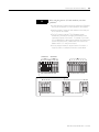
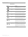
Throughout this manual, when necessary we use notes to make you aware of
safety considerations.
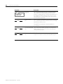
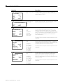
WARNING
IMPORTANT
ATTENTION
Identifies information about practices or circumstances
that can cause an explosion in a hazardous environment,
which may lead to personal injury or death, property
damage, or economic loss.
Identifies information that is critical for successful
application and understanding of the product.
Identifies information about practices or circumstances
that can lead to personal injury or death, property
damage, or economic loss. Attentions help you:
• identify a hazard
• avoid a hazard
• recognize the consequence
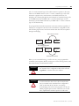
SHOCK HAZARD
Labels may be located on or inside the equipment (e.g.,
drive or motor) to alert people that dangerous voltage may
be present.
BURN HAZARD
Labels may be located on or inside the equipment (e.g.,
drive or motor) to alert people that surfaces may be
dangerous temperatures.
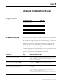
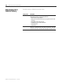
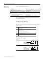
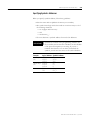
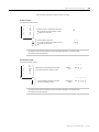
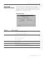
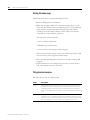
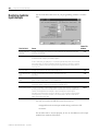
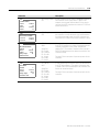
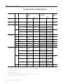
Summary of Changes
Summary of Changes
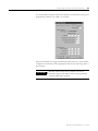
Changes to this Manual
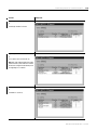
This user manual contains new and updated information.
The black revision bars, as shown on the left, indicate the changes.
For specific locations of the new information, refer to the table below.
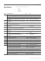
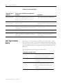
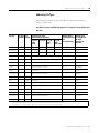
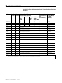
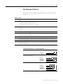
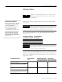
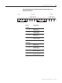
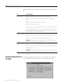
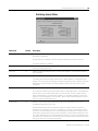
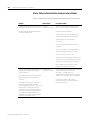
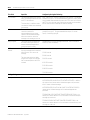
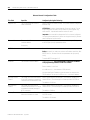
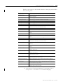
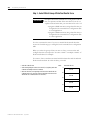
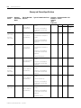
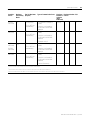
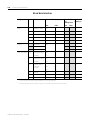
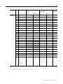
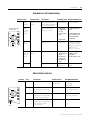
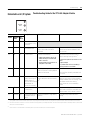
Find the New Information
This New and Updated Information
Domain Name Service
User Provided Web Pages
Multihop Messaging over Ethernet
TCP/IP Communications
Additional Ethernet Diagnostics
Memory Card Diagnostics
Troubleshooting and Diagnostics
Is on Page
11-15
11-16
11-29
11-32
11-35
B-12
F-2
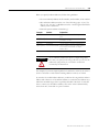
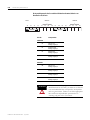
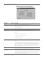
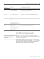
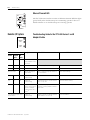
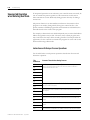
Additional Ethernet PLC-5 Controller Enhancement
Ethernet PLC-5 controllers support use of the 1785-RC Relay Cartridge.
The relay cartridge serves as an interface from the controller to a user-supplied
external device such as an Allen-Bradley 700P relay. When the controller is in
run mode, it monitors online ladder program edits and I/O forcing activity.
When either of these is detected, the controller opens the relay on the relay
cartridge for one second.
1
Publication 1785-UM012D-EN-P - July 2005
Summary of Changes
2
Notes
Publication 1785-UM012D-EN-P - July 2005
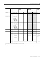
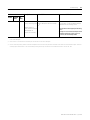
Table of Contents
Preface
Purpose of This Manual. . . . . . . . . . . . . . . . . . . . . . . . . . . . . . . . . . . .
Related PLC-5 Documentation . . . . . . . . . . . . . . . . . . . . . . . . . . . . . .
Terms Used in This Manual. . . . . . . . . . . . . . . . . . . . . . . . . . . . . . . . .
Manual Overview . . . . . . . . . . . . . . . . . . . . . . . . . . . . . . . . . . . . . . . . .
P-1
P-1
P-2
P-3
Chapter 1
Understanding Your
Programmable Controller
Using This Chapter . . . . . . . . . . . . . . . . . . . . . . . . . . . . . . . . . . . . . . . 1-1
Lay Out the System . . . . . . . . . . . . . . . . . . . . . . . . . . . . . . . . . . . . . . . 1-1
Identifying Controller Components . . . . . . . . . . . . . . . . . . . . . . . . . . 1-2
PLC-5/11, -5/20, and -5/26 Controller Front Panels . . . . . . . . . 1-3
PLC-5/40, -5/46, -5/60, -5/80, and -5/86
Controller Front Panel. . . . . . . . . . . . . . . . . . . . . . . . . . . . . . . . . . 1-5
PLC-5/20E Controller Front Panel . . . . . . . . . . . . . . . . . . . . . . 1-6
PLC-5/40E and -5/80E Controller Front Panels . . . . . . . . . . . 1-7
PLC-5/40L and -5/60L Controller Front Panels . . . . . . . . . . . 1-8
Programming Features . . . . . . . . . . . . . . . . . . . . . . . . . . . . . . . . . . . . 1-10
Using a Controller Channel as a Remote I/O Scanner . . . . . . . . . . 1-11
Using a Controller Channel as a Remote I/O Adapter . . . . . . . . . . 1-12
Using a PLC-5/40L, -5/60L Programmable Controller as an
Extended-Local I/O Scanner . . . . . . . . . . . . . . . . . . . . . . . . . . . . . . 1-14
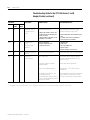
Chapter 2
Selecting and Placing I/O
Using This Chapter . . . . . . . . . . . . . . . . . . . . . . . . . . . . . . . . . . . . . . .
Selecting I/O Modules. . . . . . . . . . . . . . . . . . . . . . . . . . . . . . . . . . . . .
Guidelines for Selecting I/O Modules . . . . . . . . . . . . . . . . . . . .
Selecting I/O Module Density . . . . . . . . . . . . . . . . . . . . . . . . . . . . . .
Placing I/O Modules in a Chassis . . . . . . . . . . . . . . . . . . . . . . . . . . . .
2-1
2-1
2-2
2-2
2-3
Chapter 3
Placing System Hardware
1
Using This Chapter . . . . . . . . . . . . . . . . . . . . . . . . . . . . . . . . . . . . . . .
Determining the Proper Environment . . . . . . . . . . . . . . . . . . . . . . . .
Protecting Your Controller . . . . . . . . . . . . . . . . . . . . . . . . . . . . . . . . .
Preventing Electrostatic Discharge . . . . . . . . . . . . . . . . . . . . . . . . . . .
Laying Out Your Cable Raceway. . . . . . . . . . . . . . . . . . . . . . . . . . . . .
Categorize Conductors . . . . . . . . . . . . . . . . . . . . . . . . . . . . . . . .
Route Conductors . . . . . . . . . . . . . . . . . . . . . . . . . . . . . . . . . . .
Laying Out Your Backpanel Spacing . . . . . . . . . . . . . . . . . . . . . . . . .
Chassis Dimensions (Series B) . . . . . . . . . . . . . . . . . . . . . . . . . . .
I/O Chassis and External Power Supply Dimensions . . . . . . .
Grounding Your System . . . . . . . . . . . . . . . . . . . . . . . . . . . . . . . . . . .
3-1
3-1
3-3
3-3
3-4
3-4
3-4
3-5
3-5
3-6
3-6
Publication 1785-UM012D-EN-P - July 2005
Table of Contents
2
Chapter 4
Addressing I/O and Controller
Memory
Using This Chapter . . . . . . . . . . . . . . . . . . . . . . . . . . . . . . . . . . . . . . . 4-1
I/O Addressing Concept . . . . . . . . . . . . . . . . . . . . . . . . . . . . . . . . . . . 4-1
Choosing an Addressing Mode . . . . . . . . . . . . . . . . . . . . . . . . . . . . . . 4-3
Addressing Block-Transfer Modules. . . . . . . . . . . . . . . . . . . . . . . . . . 4-7
Addressing Summary . . . . . . . . . . . . . . . . . . . . . . . . . . . . . . . . . . . . . . 4-7
Assigning Racks . . . . . . . . . . . . . . . . . . . . . . . . . . . . . . . . . . . . . . . . . . 4-8
Understanding PLC-5 Controller Memory . . . . . . . . . . . . . . . . . . . . 4-10
Understanding Data Storage (Data-Table Files) . . . . . . . . . . . . 4-11
Addressing File Types . . . . . . . . . . . . . . . . . . . . . . . . . . . . . . . . . 4-13
Understanding Program-File Storage . . . . . . . . . . . . . . . . . . . . . 4-15
Addressing . . . . . . . . . . . . . . . . . . . . . . . . . . . . . . . . . . . . . . . . . . . . . 4-16
Specifying I/O Image Addresses . . . . . . . . . . . . . . . . . . . . . . . . 4-16
Specifying Logical Addresses . . . . . . . . . . . . . . . . . . . . . . . . . . . 4-17
Specifying Indirect Addresses . . . . . . . . . . . . . . . . . . . . . . . . . . . 4-18
Specifying Indexed Addresses. . . . . . . . . . . . . . . . . . . . . . . . . . . 4-20
Specifying Symbolic Addresses . . . . . . . . . . . . . . . . . . . . . . . . . . 4-21
Optimizing Instruction Execution Time
and Controller Memory . . . . . . . . . . . . . . . . . . . . . . . . . . . . . . . . 4-22
Effectively Using I/O Memory . . . . . . . . . . . . . . . . . . . . . . . . . . . . . 4-24
Chapter 5
Communicating with
Controller-Resident I/O
Using This Chapter . . . . . . . . . . . . . . . . . . . . . . . . . . . . . . . . . . . . . . .
Introduction to PLC-5 Controller Scanning . . . . . . . . . . . . . . . . . . . .
Program Scanning . . . . . . . . . . . . . . . . . . . . . . . . . . . . . . . . . . . . . . . .
Transferring Data to Controller-Resident I/O. . . . . . . . . . . . . . . . . .
Transferring Discrete Data to Controller-Resident I/O . . . . . . .
Transferring Immediate I/O Requests . . . . . . . . . . . . . . . . . . . . .
Transferring Block-Transfer Data to Controller-Resident I/O .
Configuring the System for Controller-Resident I/O . . . . . . . . . . . .
5-1
5-1
5-2
5-3
5-3
5-3
5-4
5-4
Chapter 6
Communicating with Remote I/O
Publication 1785-UM012D-EN-P - July 2005
Using This Chapter . . . . . . . . . . . . . . . . . . . . . . . . . . . . . . . . . . . . . . . 6-1
Selecting Devices That You Can Connect . . . . . . . . . . . . . . . . . . . . . 6-2
Introduction to Remote I/O . . . . . . . . . . . . . . . . . . . . . . . . . . . . . . . . 6-3
Designing a Remote I/O Link . . . . . . . . . . . . . . . . . . . . . . . . . . . . . . 6-4
Configuring a Controller Channel as a Scanner . . . . . . . . . . . . . . . . . 6-6
Define an I/O Status File . . . . . . . . . . . . . . . . . . . . . . . . . . . . . . . 6-7
Specify Channel Configuration Information . . . . . . . . . . . . . . . . 6-7
Specify the Scan List . . . . . . . . . . . . . . . . . . . . . . . . . . . . . . . . . . . 6-9
Communicating to a Remote I/O Node Adapter . . . . . . . . . . . . . . 6-11
Troubleshooting Remote I/O Communication Difficulties . . . 6-12
Transferring Block Data . . . . . . . . . . . . . . . . . . . . . . . . . . . . . . . . . . 6-13
Block-Transfers of Remote I/O Data . . . . . . . . . . . . . . . . . . . . . . . 6-15
Block-Transfer Sequence with Status Bits . . . . . . . . . . . . . . . . . . . . 6-17
Table of Contents
Block-Transfer Programming Considerations . . . . . . . . . . . . . . . . .
General Considerations . . . . . . . . . . . . . . . . . . . . . . . . . . . . . . . .
For Controller-Resident Local Racks . . . . . . . . . . . . . . . . . . . . .
Monitoring Remote I/O Scanner Channels . . . . . . . . . . . . . . . . . . .
Monitoring transmission retries . . . . . . . . . . . . . . . . . . . . . . . . .
Addressing the I/O Status File . . . . . . . . . . . . . . . . . . . . . . . . . . . . .
3
6-19
6-19
6-20
6-21
6-21
6-24
Chapter 7
Communicating with a PLC-5
Adapter Channel
Using This Chapter . . . . . . . . . . . . . . . . . . . . . . . . . . . . . . . . . . . . . . . 7-1
Configuring Communication to a PLC-5 Adapter Channel . . . . . . . 7-2
Specify an Adapter Channel’s Communication Rate,
Address, and Rack Size . . . . . . . . . . . . . . . . . . . . . . . . . . . . . . . . . 7-3
Specify the Discrete Transfer Configuration Files . . . . . . . . . . . . 7-5
Programming Discrete Transfers in Adapter Mode . . . . . . . . . . . . . 7-10
Programming Block-Transfers of Data to an Adapter Channel . . . 7-10
Configure Block-Transfer Requests . . . . . . . . . . . . . . . . . . . . . . 7-11
Examples of Block-Transfer Ladder Logic
Effects of Programming Block-Transfers to an Adapter-Mode
Controller Channel on Discrete Data Transfer . . . . . . . . . . . . . 7-15
Monitoring the Status of the Adapter Channel . . . . . . . . . . . . . 7-17
Monitoring the Status of the Supervisory Controller. . . . . . . . . 7-18
Monitoring Remote I/O Adapter Channels . . . . . . . . . . . . . . . . . . . 7-19
Chapter 8
Communicating with
Extended-Local I/O
Using This Chapter . . . . . . . . . . . . . . . . . . . . . . . . . . . . . . . . . . . . . . . 8-1
Selecting Devices That You Can Connect . . . . . . . . . . . . . . . . . . . . . 8-1
Cabling . . . . . . . . . . . . . . . . . . . . . . . . . . . . . . . . . . . . . . . . . . . . . . . . . 8-2
Addressing and Placing I/O . . . . . . . . . . . . . . . . . . . . . . . . . . . . . . . . 8-2
Transferring Data . . . . . . . . . . . . . . . . . . . . . . . . . . . . . . . . . . . . . . . . . 8-4
Discrete Data Transfer . . . . . . . . . . . . . . . . . . . . . . . . . . . . . . . . . 8-5
Transferring Block Data . . . . . . . . . . . . . . . . . . . . . . . . . . . . . . . . 8-6
Calculating Block-Transfer Completion Time . . . . . . . . . . . . . . . 8-7
Considerations for Extended-local Racks. . . . . . . . . . . . . . . . . . . 8-8
Configuring the Controller as an Extended-Local I/O Scanner . . . . 8-9
Monitoring Extended-Local I/O Status . . . . . . . . . . . . . . . . . . . . . . 8-12
Chapter 9
Communicating with Devices on a Using This Chapter . . . . . . . . . . . . . . . . . . . . . . . . . . . . . . . . . . . . . . . 9-1
Selecting Devices That You Can Connect . . . . . . . . . . . . . . . . . . . . . 9-1
DH+ Link
Link Design . . . . . . . . . . . . . . . . . . . . . . . . . . . . . . . . . . . . . . . . . . . . . 9-2
Configuring the Channel for DH+ Communication . . . . . . . . . . . . . 9-3
Using the Global Status Flag File . . . . . . . . . . . . . . . . . . . . . . . . . . . . 9-5
Monitoring DH+ Communication Channels . . . . . . . . . . . . . . . . . . . 9-7
Monitoring Data Sent with Acknowledgment . . . . . . . . . . . . . . . 9-8
Monitoring Data Sent without Acknowledgment . . . . . . . . . . . 9-10
Publication 1785-UM012D-EN-P - July 2005
Table of Contents
4
Monitoring General Status . . . . . . . . . . . . . . . . . . . . . . . . . . . . .
Estimating DH+ Link Performance . . . . . . . . . . . . . . . . . . . . . . . . .
Nodes . . . . . . . . . . . . . . . . . . . . . . . . . . . . . . . . . . . . . . . . . . . . . .
Size and Number of Messages . . . . . . . . . . . . . . . . . . . . . . . . . .
Message Destination . . . . . . . . . . . . . . . . . . . . . . . . . . . . . . . . . .
Internal Processing Time. . . . . . . . . . . . . . . . . . . . . . . . . . . . . . .
Average DH+ Link Response Time Test Results . . . . . . . . . . .
Application Guidelines. . . . . . . . . . . . . . . . . . . . . . . . . . . . . . . . . . . .
9-11
9-12
9-13
9-13
9-14
9-15
9-16
9-17
Chapter 10
Communicating with Devices on a Using This Chapter . . . . . . . . . . . . . . . . . . . . . . . . . . . . . . . . . . . . . . 10-1
Choosing Between RS-232C, RS-422A, and RS-423 . . . . . . . . . . . . 10-1
Serial Link
Configuring the Controller
Serial Port . . . . . . . . . . . . . . . . . . . . . . . . . . . . . . . . . . . . . . . . . . . . . . 10-2
Using Channel 0 . . . . . . . . . . . . . . . . . . . . . . . . . . . . . . . . . . . . . . . . . 10-2
User Mode . . . . . . . . . . . . . . . . . . . . . . . . . . . . . . . . . . . . . . . . . . 10-2
System Mode . . . . . . . . . . . . . . . . . . . . . . . . . . . . . . . . . . . . . . . . 10-2
Master Station to Remote Station Communication Methods . . 10-4
Polling Inactive Priority Stations. . . . . . . . . . . . . . . . . . . . . . . . . 10-5
Changing Modes . . . . . . . . . . . . . . . . . . . . . . . . . . . . . . . . . . . . . 10-5
Cabling . . . . . . . . . . . . . . . . . . . . . . . . . . . . . . . . . . . . . . . . . . . . . . . . 10-5
Configuring Channel 0 . . . . . . . . . . . . . . . . . . . . . . . . . . . . . . . . . . . . 10-6
Configure Channel 0 for DF1 Point-to-Point . . . . . . . . . . . . . . 10-6
Configure Channel 0 as a Slave Station . . . . . . . . . . . . . . . . . . . 10-9
Configure Channel 0 as a Master Station . . . . . . . . . . . . . . . . . 10-12
Configure Channel 0 for User Mode (ASCII Protocol). . . . . . 10-18
Configure Channel 0 for a Communication Mode Change. . . 10-21
Monitoring Channel 0 Status . . . . . . . . . . . . . . . . . . . . . . . . . . . . . . 10-22
Using the System Mode Status Display . . . . . . . . . . . . . . . . . . 10-22
Using the User Mode (ASCII) Status Display . . . . . . . . . . . . . 10-24
Chapter 11
Communicating with Devices on
an Ethernet Network
Publication 1785-UM012D-EN-P - July 2005
Using This Chapter . . . . . . . . . . . . . . . . . . . . . . . . . . . . . . . . . . . . . . 11-1
Media and Cabling . . . . . . . . . . . . . . . . . . . . . . . . . . . . . . . . . . . . . . . 11-1
Assigning Your IP Address . . . . . . . . . . . . . . . . . . . . . . . . . . . . . . . . 11-2
Network Addressing . . . . . . . . . . . . . . . . . . . . . . . . . . . . . . . . . . . . . 11-2
Configuring Channel 2 for Ethernet Communication . . . . . . . . . . . 11-2
Manually Configuring Channel 2 . . . . . . . . . . . . . . . . . . . . . . . . 11-2
Using BOOTP to Enter Configuration Information. . . . . . . . . 11-5
Editing the BOOTPTAB Configuration File. . . . . . . . . . . . . . . 11-7
Using Advanced Ethernet Functions . . . . . . . . . . . . . . . . . . . . . . . . 11-9
Using Broadcast Addressing . . . . . . . . . . . . . . . . . . . . . . . . . . . . 11-9
Using Subnet Masks and Gateways . . . . . . . . . . . . . . . . . . . . . 11-11
Manually Configuring Channel 2 for Controllers on Subnets . 11-12
Table of Contents
Using BOOTP to Configure Channel 2
for Controllers on Subnets . . . . . . . . . . . . . . . . . . . . . . . . . . . .
Using Domain Name Service . . . . . . . . . . . . . . . . . . . . . . . . . . . . .
Using the Embedded Web Server . . . . . . . . . . . . . . . . . . . . . . . . . .
Generating User Provided Web Pages . . . . . . . . . . . . . . . . . . .
Importing User Page Files to the PLC-5 Controller . . . . . . . .
Using Multihop Messaging . . . . . . . . . . . . . . . . . . . . . . . . . . . . . . .
Multihop Examples . . . . . . . . . . . . . . . . . . . . . . . . . . . . . . . . . .
Comparing Multihop and Non-Multihop Messages
Over Ethernet . . . . . . . . . . . . . . . . . . . . . . . . . . . . . . . . . . . . . .
Communicating with ControlLogix Devices . . . . . . . . . . . . . . . . .
TCP/IP. . . . . . . . . . . . . . . . . . . . . . . . . . . . . . . . . . . . . . . . . . . . . . .
Interpreting Error Codes . . . . . . . . . . . . . . . . . . . . . . . . . . . . . . . . .
Interpreting Ethernet Status Data . . . . . . . . . . . . . . . . . . . . . . . . . .
Monitoring general Ethernet status . . . . . . . . . . . . . . . . . . . . .
Monitoring Ethernet commands. . . . . . . . . . . . . . . . . . . . . . . .
Monitoring Ethernet replies . . . . . . . . . . . . . . . . . . . . . . . . . . .
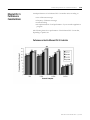
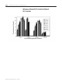
Ethernet PLC-5 Performance Considerations . . . . . . . . . . . . . . . .
Performance: Host to Ethernet PLC-5 Controller. . . . . . . . . .
Performance: Ethernet PLC-5 Controller to Ethernet
PLC-5 Controller . . . . . . . . . . . . . . . . . . . . . . . . . . . . . . . . . . . .
5
11-13
11-15
11-16
11-22
11-26
11-29
11-30
11-32
11-32
11-32
11-33
11-34
11-35
11-36
11-36
11-37
11-37
11-38
Chapter 12
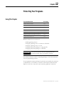
Protecting Your Programs
Using This Chapter . . . . . . . . . . . . . . . . . . . . . . . . . . . . . . . . . . . . . .
About Passwords and Privileges . . . . . . . . . . . . . . . . . . . . . . . . . . . .
Defining Privilege Classes . . . . . . . . . . . . . . . . . . . . . . . . . . . . . . . . .
Assigning a Privilege Class to a Channel or Offline File . . . . . . . . .
Assigning a Privilege Class to a Node . . . . . . . . . . . . . . . . . . . . . . . .
Assigning Read/Write Privileges to a Program File . . . . . . . . . . . . .
Assigning Read/Write Privileges to a Data File . . . . . . . . . . . . . . . .
12-1
12-2
12-3
12-4
12-4
12-5
12-5
Chapter 13
Programming Considerations
Using This Chapter . . . . . . . . . . . . . . . . . . . . . . . . . . . . . . . . . . . . . .
Forcing . . . . . . . . . . . . . . . . . . . . . . . . . . . . . . . . . . . . . . . . . . . . . . . .
Forcing Inputs and Outputs . . . . . . . . . . . . . . . . . . . . . . . . . . . .
Forcing SFC Transitions . . . . . . . . . . . . . . . . . . . . . . . . . . . . . . .
Extended Forcing. . . . . . . . . . . . . . . . . . . . . . . . . . . . . . . . . . . . . . . .
Increased Program Scan Time . . . . . . . . . . . . . . . . . . . . . . . . . .
I/O Force Privileges . . . . . . . . . . . . . . . . . . . . . . . . . . . . . . . . . .
Using Protected Controllers . . . . . . . . . . . . . . . . . . . . . . . . . . . .
Using Selectable Timed Interrupts (STIs)
and Controller Input Interrupts (PIIs) . . . . . . . . . . . . . . . . . . . .
Setting Up and Using Extended Forcing . . . . . . . . . . . . . . . . . . . . .
Step 1 - Select Which Group of Data You Want to Force . . . .
13-1
13-1
13-1
13-2
13-2
13-4
13-4
13-5
13-5
13-5
13-6
Publication 1785-UM012D-EN-P - July 2005
Table of Contents
6
Step 2 - Use the Programming Software to Enter
or Edit the Data You Want to Force in the Extended Force
Configuration Table. . . . . . . . . . . . . . . . . . . . . . . . . . . . . . . . . . . 13-7
Step 3 - Use the Programming Software to Enter
Force Values for the Specified Data Table Files . . . . . . . . . . . . 13-8
Step 4 - Enable or Disable the Forces . . . . . . . . . . . . . . . . . . . . 13-8
Using Extended Forcing with Time-Critical Applications. . . . . 13-8
Using Special Programming Routines . . . . . . . . . . . . . . . . . . . . . . . 13-10
Priority Scheduling for Interrupts and MCPs . . . . . . . . . . . . . . . . . 13-11
Program Execution States . . . . . . . . . . . . . . . . . . . . . . . . . . . . . 13-12
Influencing Priority Scheduling. . . . . . . . . . . . . . . . . . . . . . . . . 13-14
Defining and Programming Interrupt Routines . . . . . . . . . . . . . . . 13-15
Chapter 14
Preparing Power-Up Routines
Using This Chapter . . . . . . . . . . . . . . . . . . . . . . . . . . . . . . . . . . . . . .
Setting Power-Up Protection. . . . . . . . . . . . . . . . . . . . . . . . . . . . . . .
Allowing or Inhibiting Startup. . . . . . . . . . . . . . . . . . . . . . . . . . . . . .
Defining a Controller Power-Up Procedure. . . . . . . . . . . . . . . . . . .
14-1
14-1
14-2
14-2
Chapter 15
Preparing Fault Routines
Publication 1785-UM012D-EN-P - July 2005
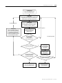
Using This Chapter . . . . . . . . . . . . . . . . . . . . . . . . . . . . . . . . . . . . . . 15-1
Understanding the Fault Routine Concept . . . . . . . . . . . . . . . . . . . . 15-1
Responses to a Major Fault . . . . . . . . . . . . . . . . . . . . . . . . . . . . . 15-1
Understanding Controller-Detected Major Faults . . . . . . . . . . . . . . 15-2
Fault in a Controller-Resident or Extended-Local I/O Rack . . 15-3
Fault in a Remote I/O Chassis . . . . . . . . . . . . . . . . . . . . . . . . . . 15-3
Defining a Fault Routine . . . . . . . . . . . . . . . . . . . . . . . . . . . . . . . . . . 15-4
Defining a Watchdog Timer . . . . . . . . . . . . . . . . . . . . . . . . . . . . . . . 15-5
Avoiding Multiple Watchdog Faults . . . . . . . . . . . . . . . . . . . . . . 15-6
Programming a Fault Routine . . . . . . . . . . . . . . . . . . . . . . . . . . . . . . 15-6
Setting an Alarm. . . . . . . . . . . . . . . . . . . . . . . . . . . . . . . . . . . . . . 15-7
Clearing a Major Fault . . . . . . . . . . . . . . . . . . . . . . . . . . . . . . . . . 15-7
Changing the Fault Routine from Ladder Logic . . . . . . . . . . . . 15-9
Using Ladder Logic to Recover from a Fault. . . . . . . . . . . . . . 15-10
Block-Transfers in Fault Routines . . . . . . . . . . . . . . . . . . . . . . 15-11
Testing a Fault Routine . . . . . . . . . . . . . . . . . . . . . . . . . . . . . . . 15-11
Monitoring Faults. . . . . . . . . . . . . . . . . . . . . . . . . . . . . . . . . . . . . . . 15-11
Monitoring Major/Minor Faults and Fault Codes . . . . . . . . . . 15-12
Interpreting Major Faults . . . . . . . . . . . . . . . . . . . . . . . . . . . . . 15-12
Interpreting Minor Faults . . . . . . . . . . . . . . . . . . . . . . . . . . . . . 15-12
Monitoring Status Bits . . . . . . . . . . . . . . . . . . . . . . . . . . . . . . . . 15-13
Table of Contents
7
Chapter 16
Using Main Control Programs
Using This Chapter . . . . . . . . . . . . . . . . . . . . . . . . . . . . . . . . . . . . . .
Selecting Main Control Programs . . . . . . . . . . . . . . . . . . . . . . . . . . .
Understanding How the
Controller Interprets MCPs . . . . . . . . . . . . . . . . . . . . . . . . . . . . . . . .
Configuring MCPs . . . . . . . . . . . . . . . . . . . . . . . . . . . . . . . . . . . . . . .
Monitoring MCPs. . . . . . . . . . . . . . . . . . . . . . . . . . . . . . . . . . . . . . . .
16-1
16-1
16-2
16-3
16-5
Chapter 17
Using Selectable Timed Interrupts Using This Chapter . . . . . . . . . . . . . . . . . . . . . . . . . . . . . . . . . . . . . . 17-1
Using a Selectable Timed Interrupt. . . . . . . . . . . . . . . . . . . . . . . . . .
Writing STI Ladder Logic . . . . . . . . . . . . . . . . . . . . . . . . . . . . . .
STI Application Example . . . . . . . . . . . . . . . . . . . . . . . . . . . . . .
Block-Transfers in Selectable Timed Interrupts (STIs) . . . . . . .
Defining a Selectable Timed Interrupt . . . . . . . . . . . . . . . . . . . . . . .
Monitoring Selectable Timed Interrupts . . . . . . . . . . . . . . . . . . . . . .
17-1
17-1
17-2
17-2
17-3
17-4
Chapter 18
Using Processor Input Interrupts
Using This Chapter . . . . . . . . . . . . . . . . . . . . . . . . . . . . . . . . . . . . . .
Using a Processor Input Interrupt. . . . . . . . . . . . . . . . . . . . . . . . . . .
Writing PII Ladder Logic . . . . . . . . . . . . . . . . . . . . . . . . . . . . . .
PII Application Examples . . . . . . . . . . . . . . . . . . . . . . . . . . . . . .
Block-Transfers in Processor Input Interrupts (PIIs) . . . . . . . .
Design Considerations. . . . . . . . . . . . . . . . . . . . . . . . . . . . . . . . .
Defining a Controller Input Interrupt. . . . . . . . . . . . . . . . . . . . . . . .
Monitoring Controller Input Interrupts . . . . . . . . . . . . . . . . . . . . . .
18-1
18-1
18-2
18-2
18-3
18-4
18-5
18-6
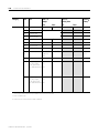
Appendix A
System Specifications
Controller Specifications . . . . . . . . . . . . . . . . . . . . . . . . . . . . . . .
Memory and Channel Specifications. . . . . . . . . . . . . . . . . . . . . .
Memory Backup Devices . . . . . . . . . . . . . . . . . . . . . . . . . . . . . . . . . .
EEPROM Compatibility . . . . . . . . . . . . . . . . . . . . . . . . . . . . . . .
A-1
A-2
A-4
A-5
Appendix B
Processor Status File
. . . . . . . . . . . . . . . . . . . . . . . . . . . . . . . . . . . . . . . . . . . . . . . . . . . . . . . . B-1
S:0 - S:2 . . . . . . . . . . . . . . . . . . . . . . . . . . . . . . . . . . . . . . . . . . . . . . . . . B-1
S:3-10 . . . . . . . . . . . . . . . . . . . . . . . . . . . . . . . . . . . . . . . . . . . . . . . . . . B-3
S:11 . . . . . . . . . . . . . . . . . . . . . . . . . . . . . . . . . . . . . . . . . . . . . . . . . . . . B-4
S:12 . . . . . . . . . . . . . . . . . . . . . . . . . . . . . . . . . . . . . . . . . . . . . . . . . . . . B-5
S:13-S:24 . . . . . . . . . . . . . . . . . . . . . . . . . . . . . . . . . . . . . . . . . . . . . . . . B-9
S:26-S:35 . . . . . . . . . . . . . . . . . . . . . . . . . . . . . . . . . . . . . . . . . . . . . . . B-10
S:36-S:78 . . . . . . . . . . . . . . . . . . . . . . . . . . . . . . . . . . . . . . . . . . . . . . . B-11
S:79-S:127 . . . . . . . . . . . . . . . . . . . . . . . . . . . . . . . . . . . . . . . . . . . . . . B-12
Publication 1785-UM012D-EN-P - July 2005
Table of Contents
8
Appendix C
Maximizing System Performance
Using This Chapter . . . . . . . . . . . . . . . . . . . . . . . . . . . . . . . . . . . . . . . C-1
Program Scan . . . . . . . . . . . . . . . . . . . . . . . . . . . . . . . . . . . . . . . . . . . . C-1
Effects of False Logic versus True Logic on Logic Scan Time. . C-2
Effects of Different Input States on Logic Scan Time . . . . . . . . C-2
Effects of Different Instructions on Logic Scan Time . . . . . . . . C-3
Effects of Using Interrupts on Logic Scan Time . . . . . . . . . . . . . C-3
Effects of Housekeeping Time . . . . . . . . . . . . . . . . . . . . . . . . . . . C-4
Editing While in Remote Run Mode . . . . . . . . . . . . . . . . . . . . . . C-4
Putting Block-Transfer Modules in Controller-Resident Chassis C-5
Using Global Status Flag Files . . . . . . . . . . . . . . . . . . . . . . . . . . . C-5
Calculating Throughput. . . . . . . . . . . . . . . . . . . . . . . . . . . . . . . . . C-5
Input and Output Modules Delay . . . . . . . . . . . . . . . . . . . . . . . . . . . . C-6
I/O Backplane Transfer. . . . . . . . . . . . . . . . . . . . . . . . . . . . . . . . . . . . C-6
Remote I/O Scan Time . . . . . . . . . . . . . . . . . . . . . . . . . . . . . . . . . . . . C-6
Communication Rate . . . . . . . . . . . . . . . . . . . . . . . . . . . . . . . . . . . C-7
Number of Rack Entries . . . . . . . . . . . . . . . . . . . . . . . . . . . . . . . . C-7
Block-Transfers . . . . . . . . . . . . . . . . . . . . . . . . . . . . . . . . . . . . . . . C-8
Calculating Worst-Case Remote I/O Scan Time . . . . . . . . . . . . . C-9
Optimizing Remote I/O Scan Time. . . . . . . . . . . . . . . . . . . . . . . C-9
Controller Time . . . . . . . . . . . . . . . . . . . . . . . . . . . . . . . . . . . . . . . . . C-11
Example Calculation . . . . . . . . . . . . . . . . . . . . . . . . . . . . . . . . . . . . . C-12
Performance Effects of Online Operations . . . . . . . . . . . . . . . . . . . C-12
Effect of Inserting Ladder Rungs at the 56K-word Limit . . . . . . . . C-13
Using Program Control Instructions. . . . . . . . . . . . . . . . . . . . . . . . . C-14
Using JMP/LBL Instructions . . . . . . . . . . . . . . . . . . . . . . . . . . . C-14
Using FOR/NXT Instructions . . . . . . . . . . . . . . . . . . . . . . . . . . C-14
Appendix D
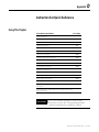
Instruction Set Quick Reference
Publication 1785-UM012D-EN-P - July 2005
Using This Chapter . . . . . . . . . . . . . . . . . . . . . . . . . . . . . . . . . . . . . . D-1
Relay Instructions . . . . . . . . . . . . . . . . . . . . . . . . . . . . . . . . . . . . D-2
Timer Instructions . . . . . . . . . . . . . . . . . . . . . . . . . . . . . . . . . . . . D-3
Counter Instructions . . . . . . . . . . . . . . . . . . . . . . . . . . . . . . . . . . D-4
Compare Instructions . . . . . . . . . . . . . . . . . . . . . . . . . . . . . . . . . D-5
Compute Instructions . . . . . . . . . . . . . . . . . . . . . . . . . . . . . . . . . D-7
Logical Instructions . . . . . . . . . . . . . . . . . . . . . . . . . . . . . . . . . . D-14
Conversion Instructions . . . . . . . . . . . . . . . . . . . . . . . . . . . . . . D-15
Bit Modify and Move Instructions . . . . . . . . . . . . . . . . . . . . . . D-16
File Instructions . . . . . . . . . . . . . . . . . . . . . . . . . . . . . . . . . . . . . D-17
Diagnostic Instructions . . . . . . . . . . . . . . . . . . . . . . . . . . . . . . . D-19
Shift Register Instructions . . . . . . . . . . . . . . . . . . . . . . . . . . . . . D-20
Sequencer Instructions . . . . . . . . . . . . . . . . . . . . . . . . . . . . . . . D-21
Program Control Instructions . . . . . . . . . . . . . . . . . . . . . . . . . . D-22
Process Control, Message Instructions. . . . . . . . . . . . . . . . . . . D-25
Block Transfer Instructions. . . . . . . . . . . . . . . . . . . . . . . . . . . . D-25
Table of Contents
9
ASCII Instructions . . . . . . . . . . . . . . . . . . . . . . . . . . . . . . . . . . D-27
Bit and Word Instructions. . . . . . . . . . . . . . . . . . . . . . . . . . . . . D-30
File, Program Control, and ASCII Instructions . . . . . . . . . . . . D-32
Appendix E
Switch Setting Reference
Using This Chapter . . . . . . . . . . . . . . . . . . . . . . . . . . . . . . . . . . . . . . . E-1
Controller Switches . . . . . . . . . . . . . . . . . . . . . . . . . . . . . . . . . . . . . . . E-2
Switch 1 . . . . . . . . . . . . . . . . . . . . . . . . . . . . . . . . . . . . . . . . . . . . . E-2
Switch 2 . . . . . . . . . . . . . . . . . . . . . . . . . . . . . . . . . . . . . . . . . . . . . E-3
I/O Chassis Backplane . . . . . . . . . . . . . . . . . . . . . . . . . . . . . . . . . . . . E-4
PLC-5 Controller in the I/O Chassis . . . . . . . . . . . . . . . . . . . . . . E-4
1771-ASB Remote I/O Adapter or 1771-ALX
Extended-Local I/O Adapter . . . . . . . . . . . . . . . . . . . . . . . . . . . . E-5
I/O Chassis Configuration Plug . . . . . . . . . . . . . . . . . . . . . . . . . . E-6
Remote I/O Adapter Module . . . . . . . . . . . . . . . . . . . . . . . . . . . . . . . E-7
(1771-ASB Series C and D) without Complementary I/O . . . . . E-7
(1771-ASB Series C and D) I/O Rack Number without Complementary I/O . . . . . . . . . . . . . . . . . . . . . . . . . . . . E-8
Extended-Local I/O Adapter Module . . . . . . . . . . . . . . . . . . . . . . . . E-9
(1771-ALX) Switch SW1 . . . . . . . . . . . . . . . . . . . . . . . . . . . . . . . . E-9
(1771-ALX) Configuration Plug . . . . . . . . . . . . . . . . . . . . . . . . . E-10
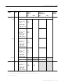
Appendix F
Troubleshooting
Using This Chapter . . . . . . . . . . . . . . . . . . . . . . . . . . . . . . . . . . . . . . . F-1
PLC-5 Controller . . . . . . . . . . . . . . . . . . . . . . . . . . . . . . . . . . . . . . . . . F-2
General Problems . . . . . . . . . . . . . . . . . . . . . . . . . . . . . . . . . . . . . F-2
Controller Communication Channel Troubleshooting . . . . . . . . F-4
Extended-Local I/O Troubleshooting . . . . . . . . . . . . . . . . . . . . . F-5
Ethernet Status Indicator . . . . . . . . . . . . . . . . . . . . . . . . . . . . . . . F-5
Ethernet Transmit LED . . . . . . . . . . . . . . . . . . . . . . . . . . . . . . . . F-6
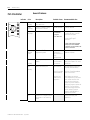
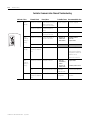
Remote I/O System . . . . . . . . . . . . . . . . . . . . . . . . . . . . . . . . . . . . . . . F-6
Troubleshooting Guide for the 1771-ASB Series C and D
Adapter Module . . . . . . . . . . . . . . . . . . . . . . . . . . . . . . . . . . . . . . . F-6
Troubleshooting Guide for the 1771-ASB Series C and D
Adapter Module (continued) . . . . . . . . . . . . . . . . . . . . . . . . . . . . . F-8
Extended-Local I/O System . . . . . . . . . . . . . . . . . . . . . . . . . . . . . . . . F-9
Troubleshooting Guide for the 1771-ALX Adapter Module . . . F-9
Unexpected Operation when Entering Run Mode. . . . . . . . . . . . . . . F-9
Instructions with Unique Prescan Operations . . . . . . . . . . . . . . F-10
Suggested Action . . . . . . . . . . . . . . . . . . . . . . . . . . . . . . . . . . . . . F-11
Publication 1785-UM012D-EN-P - July 2005
Table of Contents
10
Appendix G
Cable Reference
Index
Publication 1785-UM012D-EN-P - July 2005
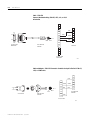
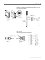
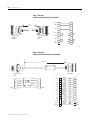
Using This Chapter . . . . . . . . . . . . . . . . . . . . . . . . . . . . . . . . . . . . . .
Channel 0 Pin Assignments . . . . . . . . . . . . . . . . . . . . . . . . . . . . . . . .
Serial Cable Pin Assignments. . . . . . . . . . . . . . . . . . . . . . . . . . . . . . .
Connecting Diagrams. . . . . . . . . . . . . . . . . . . . . . . . . . . . . . . . . . . . .
Programming Cable Specifications . . . . . . . . . . . . . . . . . . . . . . . . . .
Ethernet Cable Connections . . . . . . . . . . . . . . . . . . . . . . . . . . . . . . .
G-1
G-1
G-2
G-3
G-5
G-9
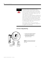
Preface
Using This Manual
Purpose of This Manual
The purpose of this manual is to help you design, operate and maintain an
Enhanced and Ethernet PLC-5 programmable controller system. Use this
manual to:
• determine the features of the controllers and how you use them
• design your PLC-5 system
• operate and maintain your PLC-5 system
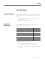
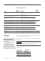
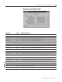
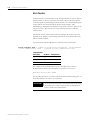
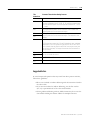
Related PLC-5
Documentation
The following documents contain additional information related to the
procedures described in this document..
Publication Title
Publication Number
Industrial Automation Wiring and Grounding Guidelines
1770-4.1
PLC-5 Programmable Controller Instruction Set Reference
1785-6.1
Configuring Complementary I/O for PLC-5 Controllers
1785-6.8.3
Data Highway Cable Installation Manual
1770-6.2.2
SCADA System Selection Guide,
AG-SG001
PLC-5 Protected Controllers Product Data
1785-2.28
PLC-5 Protected Controller Supplement
1785-6.5.13
1771 Remote I/O Adapter Module User Manual
1771-UM001
ControlNet PLC-5 Programmable Controllers User Manual
1785-UM022
To get this documentation, you can either:
• view or download an electronic version from the internet at
www.rockwellautomation.com/literature
• contact your local distributor or Rockwell Automation representative to
place an order
1
Publication 1785-UM012D-EN-P - July 2005
Preface
2
Terms Used in This Manual
Become familiar with the following terms and definitions which are used
throughout this manual.
Term
Definition
Block-transfer data
data transferred, in blocks of data up to 64 words, to/from a blocktransfer I/O module (for example, an analog module)
Discrete-transfer data
data (words) transferred to/from a discrete I/O module
Enhanced PLC-5 controllers
references PLC-5/11, -5/20, -5/26, -5/30, -5/40, -5/46, -5/40L,
-5/46L, -5/60, -5/60L, -5/80, and -5/86 controllers
PLC-5/26, -5/46, and -5/86 controllers are protected
controllers. See the PLC-5 Protected Controllers Supplement,
publication 1785-6.5.13
This term also refers to the PLC-5/V30B, -5/V40B, -5/V40L, and
-5/V80B controllers when applicable. See the PLC-5/VME VMEbus
Programmable Controllers User Manual, publication 1785-6.5.9,
for more information
Ethernet
a local area network with a baseband communication rate of 10M
bps designed for the high-speed exchange of information between
computers and related devices
Ethernet PLC-5 controllers
references PLC-5/20E, -5/40E, and -5/80E controllers
Extended-local I/O
I/O connected to a controller across a parallel link to achieve
higher throughput, thus limiting its distance from the controller
Extended local I/O link
a parallel link for carrying I/O data between a PLC-5/40L or -5/60L
controller and extended-local I/O adapters
PLC-5 controller
used to generically reference Enhanced PLC-5 and Ethernet PLC-5
controllers in this manual only
Controller-resident local I/O
chassis
the I/O chassis in which the PLC-5 controller is installed
Remote I/O link
a serial communication link between a PLC-5 controller port in
scanner mode and an adapter as well as I/O modules that are
located remotely from the PLC-5 controller
Remote I/O chassis
the hardware enclosure that contains an adapter and I/O modules
that are located remotely on a serial communication link to a PLC-5
controller in scanner mode
Publication 1785-UM012D-EN-P - July 2005
Preface
Manual Overview
3
This manual has three main sections:
• Design
• Operate
• Maintain
Section:
For information about:
Design
An overview of the PLC-5 controllers’ capabilities and keyswitch
Chapter 1
Understanding Your Controller
Guidelines for selecting and placing I/O modules
Chapter 2
Selecting and Placing I/O
The proper environment for your PLC-5 system
Chapter 3
Placing System Hardware
Choosing addressing mode, assigning rack numbers, and understanding
PLC-5 memory
Chapter 4
Addressing I/O and Controller Memory
Configuring the controller for controller-resident I/O, transferring data, and
monitoring status
Chapter 5
Communicating with Controller-Resident I/O
Configuring a system for remote I/O communication, designing a remote
I/O link, transferring data, and monitoring status
Chapter 6
Communicating with Remote I/O
Configuring a PLC-5 adapter channel, transferring data, and
monitoring status
Chapter 7
Communicating with a PLC-5
Adapter Channel
For PLC-5/40L, -5/46L, and -5/60L Controllers only: Configuring an
extended-local I/O system, transferring data, and monitoring status
Chapter 8
Communicating with Extended-Local I/O
Configuring a system for Data Highway Plus™ and monitoring
channel status
Chapter 9
Communicating with Devices on a DH+ Link
Configuring a system for serial communications and monitoring
channel status
Chapter 10 Communicating with Devices on a
Serial Link
For PLC-5/20E, -5/40E, and -5/80E Controllers only:
Configuring a system for Ethernet communications and monitoring
channel status
Chapter 11 Communicating with Devices on an
Ethernet Network
Assigning passwords and privileges
Chapter 12 Protecting Your Programs
PLC-5 programming feature overview
Chapter 13 Programming Considerations
Defining power-up procedure
Chapter 14 Preparing Power-Up Routines
Defining, programming, and monitoring fault routines
Chapter 15 Preparing Fault Routines
Configuring and monitoring main control programs
Chapter 16 Using Main Control Programs
Using, defining, and monitoring selectable timed interrupts
Chapter 17 Using Selectable Timed Interrupts
Using, defining, and monitoring Controller input interrupts
Chapter 18 Using Controller Input Interrupts
System specifications
Appendix A System Specifications
Listing of the controller status file words and meaning
Appendix B Controller Status File
General and specific performance considerations
Appendix C Maximizing System Performance
Guide to ladder instructions and execution times
Appendix D Instruction Set Quick Reference
How to set system switches
Appendix E Switch Setting Reference
Potential problems and recommended solutions
Appendix F Troubleshooting
Guidelines for choosing and making cables
Appendix G Cable Reference
Operate
Maintain
See
Title:
Publication 1785-UM012D-EN-P - July 2005
Preface
4
Notes
Publication 1785-UM012D-EN-P - July 2005
Chapter
1
Understanding Your Programmable Controller
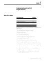
Using This Chapter
For Information About
Lay Out the System
Identifying controller components
Programming features
Using a controller channel as a remote I/O scanner
Using a controller channel as a remote I/O adapter
Using a PLC-5/40L, -5/60L programmable controller as an
extended-local I/O scanner
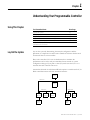
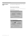
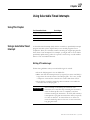
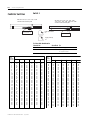
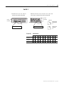
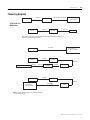
Lay Out the System
Go to Page
1-1
1-2
1-10
1-11
1-12
1-14
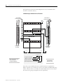
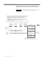
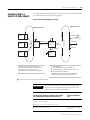
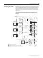
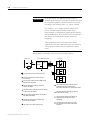
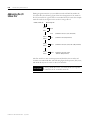
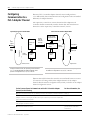
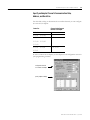
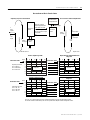
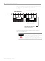
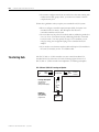
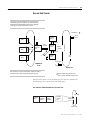
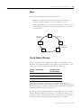
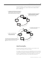
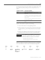
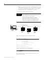
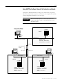
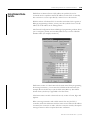
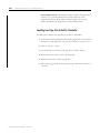
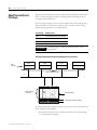
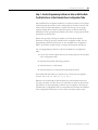
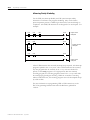
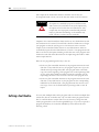
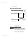
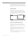
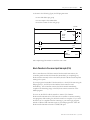
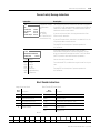
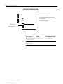
Lay out the system by determining the network configuration and the
placement of components in each location. Decide at this time whether each
location will have its own controller.
Place each controller’s I/O on an isolated network to maximize the
performance and to more easily accommodate future network or system
configuration changes. If you plan to share I/O, make sure the I/O is on a
network that each controller can access.
Assume that Network A and Network B both require a controller and its I/O.
Both controllers interact with time critical information.
RSView
Network C
Panel C
Network B
Network A
Panel A
chassis 1
Panel
View
1
Panel A
chassis 2
Panel A
chassis 3
Panel B
chassis 1
Panel B
chassis 2
Panel
View
Publication 1785-UM012D-EN-P - July 2005
1-2
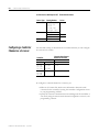
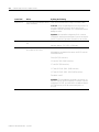
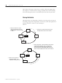
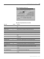
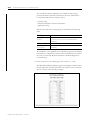
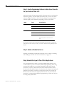
Understanding Your Programmable Controller
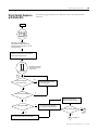
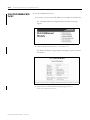
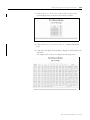
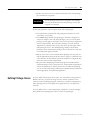
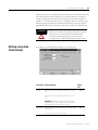
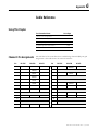
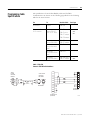
For a PLC-5 controller to control I/O modules, both the controller and the
I/O modules must be directly attached to the same network.
I/O Location
Controller in
Panel A, chassis 1
Controller in
Panel B, chassis 1
Panel A, chassis 1
yes
yes
Panel A, chassis 2
yes
no
Panel A, chassis 3
yes
no
Panel B, chassis 1
yes
yes
Panel B, chassis 2
no
yes
Panel C, chassis 1
yes
yes
Evaluate what communications need to occur between controllers. If there is
sporadic information that is not time-critical, use a message-based network
such as an EtherNet/IP (the information portion) or Data Highway PlusTM.
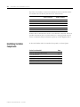
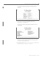
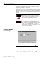
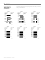
Identifying Controller
Components
To become familiar with the controller’s front panels, use these figures:
For the Front Panels Of
PLC-5/11, -5/20 and -5/26 controllers
PLC-5/30 controllers
PLC-5/40, -5/46, -5/60, -5/80 and -5/86 controllers
PLC-5/20E controllers
PLC-5/40E and -5/80E controllers
PLC-5/40L and -5/60L controllers
Publication 1785-UM012D-EN-P - July 2005
Page
1-3
1-4
1-5
1-6
1-7
1-8
Understanding Your Programmable Controller
1-3
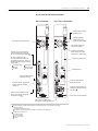
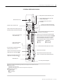
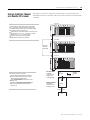
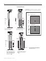
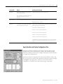
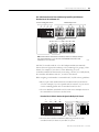
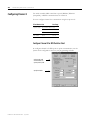
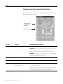
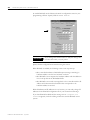
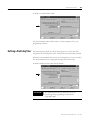
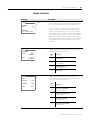
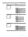
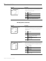
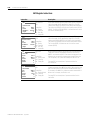
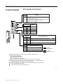
PLC-5/11, -5/20, and -5/26 Controller Front Panels
PLC-5/11 Controller
PLC-5/20 or -5/26 Controller
battery indicator (red when
the battery is low)
controller RUN/FAULT
indicator (green when
running; red when faulted)
keyswitch; selects controller mode
force indicator (amber when
I/O forces are enabled)
channel 0 communication
status indicator (green when
the channel is communicating)
channel 0-25-pin D-shell serial port;
supports standard EIA RS-232C and
RS-423 and is RS-422A compatible 1
Use this port with ASCII or DF1
full-duplex, half-duplex master, and
half-duplex slave protocols. The port's
default configuration supports controller
programming:
DF1 point-to-point
2400 bps
no parity
Install memory module here.
one stop-bit
BCC error check
no handshaking
Install battery here
channel 1A status indicator
(lights green and red)
channel 1B status indicator
(lights green and red)
8-pin mini-DIN, DH+ programming
terminal connection parallel to
channel 1A
channel 1B communication port;
its default configuration is remote
I/O scanner 2
channel 1A communication port; for
the PLC-5/11 controller, the default
configuration is DH+ 2
PLC-5 family member designation
channel 1A communication port;
this 3-pin port is a dedicated DH+ port
1 Channel 0 is optically-coupled (provides high electrical noise immunity) and can be used with most RS-422A
equipment as long as:
termination resistors are not used
the distance and transmission rate are reduced to comply with RS-423 requirements
2 Configure these 3-pin ports for:
remote I/O scanner
remote I/O adapter,
DH+ communication
unused
Publication 1785-UM012D-EN-P - July 2005
1-4
Understanding Your Programmable Controller
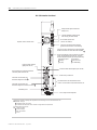
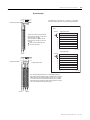
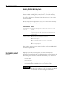
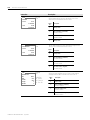
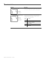
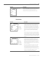
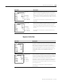
PLC-5/30 Controller Front Panell
battery indicator (lights red when the
battery is low)
controller RUN/FAULT indicator (green
when running; red when faulted)
force indicator (amber when
I/O forces are enabled)
keyswitch; selects controler mode
channel 0 communication status indicator
(green when the channel is communicating)
channel 0-25-pin D-shell serial port; supports standard
EIA RS-232C and RS-423 and is RS-422A compatible 1
Use this port with ASCII or DF1 full-duplex, half-duplex
master, and half-duplex slave protocols. The port's
default configuration supports processor programming:
DF1 point-to-point
one stop-bit
2400 bps
BCC error check
no parity
no handshaking
channel 1A status indicator
(lights green and red)
channel 1B status indicator (lights green and red)
8-pin mini-DIN, DH+ programming terminal
connection parallel to channel 1A
Install memory module here
channel 1A communication port;
its default configuration is DH+ 2
channel 1B communication port;
its default configuration is remote I/O scanner 2
Use these labels to write information about the
channel: communication mode, station addresses, etc.
Install battery here
PLC-5 family member designation
1 Channel 0 is optically-coupled (provides high electrical noise immunity) and can be used with most RS-422
equipment as long as:
termination resistors are not used
the distance and transmission rate are reduced to comply with RS-423 requirements
2 Configure these 3-pin ports for:
remote I/O scanner,
remote I/O adapter,
DH+ communication
unused
Publication 1785-UM012D-EN-P - July 2005
Understanding Your Programmable Controller
1-5
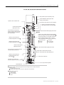
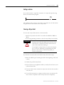
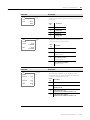
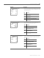
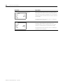
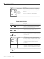
PLC-5/40, -5/46, -5/60, -5/80, and -5/86 Controller Front Panel
battery indicator (red when the battery is low)
controler RUN/FAULT indicator (green when
running; red when faulted)
keyswitch; selects controller mode
force indicator (amber when I/O forces are enabled)
channel 0 communication status indicator
(green when the channel is communicating)
channel 2A status indicator
(lights green and red)
8-pin mini-DIN, DH+ programming
terminal connection parallel to channel
2A when channel 2A is configured for
DH+ communications
channel 2B status indicator (lights green and red)
channel 0-25-pin D-shell serial port; supports standard
EIA RS-232C and RS-423 and is RS-422A compatible 1
channel 2A communication port;
its default configuration is unused 2
channel 2B communication port;
its default configuration is unused 2
channel 1A status indicator
(lights green and red)
Use this port with ASCII or DF1 full-duplex, half-duplex
master, and half-duplex slave protocols. The port's
default configuration supports processor programming:
DF1 point-to-point
2400 bps
no parity
one stop-bit
BCC error check
no handshaking
channel 1B status indicator (lights green and red)
8-pin mini-DIN, DH+ programming terminal
connection parallel to channel 1A
Use these labels to write information about the
channel: communication mode, station addresses etc.
channel 1A communication port;
its default configuration is DH+
at 57.6 kbps 2
Install memory module here
channel 1B communication port;
its default configuration is remote I/O scanner 2
PLC-5 family member designation
Install battery here
1 Channel 0 is optically-coupled (provides high electrical noise immunity) and can be used with most RS-422A
equipment as long as:
termination resistors are not used
the distance and transmission rate are reduced to comply with RS-423 requirements
2 Configure these 3-pin ports for:
remote I/O scanner,
remote I/O adapter,
DH+ communication
unused
Publication 1785-UM012D-EN-P - July 2005
1-6
Understanding Your Programmable Controller
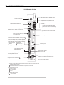
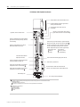
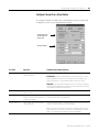
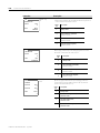
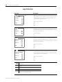
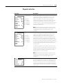
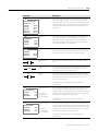
PLC-5/20E Controller Front Panel
battery indicator (red when the battery is low)
external transceiver fuse
controller RUN/FAULT indicator (green when
running; red when faulted)
force indicator (amber when I/O forces
are enabled)
keyswitch; selects controller mode
channel 0 communication status indicator
(green when the channel is communicating)
channel 2 Ethernet status indicator (green when
functioning normally; red when not functioning)
channel 2, Ethernet transmit indicator
(green when the channel is communicating)
channel 2 communication port;
a 15-pin Ethernet port
Install memory module here
channel 0*25-pin D-shell serial port; supports standard
EIA RS-232C and RS-423 and is RS-422A compatible 1
Use this port with ASCII or DF1 full-duplex, half-duplex
master, and half-duplex slave protocols. The port's
default configuration supports controller programming:
DF1 point-to-point
2400 bps
no parity
one stop-bit
BCC error check
no handshaking
Install battery here
channel 1A status indicator
(lights green and red)
channel 1B status indicator
(lights green and red)
8-pin mini-DIN, DH+ programming terminal
connection parallel to channel 1A
channel 1B communication port;
its default configuration is remote I/O scanner 2
channel 1A communication port; its default
configuration is DH+ communication 3
PLC-5/20E
Programmable
Controller
PLC-5 family member designation
1 Channel 0 is optically-coupled (provides high electrical noise immunity) and can be used with most RS-422A
equipment as long as:
termination resistors are not used
the distance and transmission rate are reduced to comply with RS-423 requirements
2 Configure these 3-pin ports for:
remote I/O scanner
remote I/O adapter
DH+ communication
unused
3 Configure this 3-pin port for:
remote I/O adapter
DH+ communication
Publication 1785-UM012D-EN-P - July 2005
Understanding Your Programmable Controller
1-7
PLC-5/40E and -5/80E Controller Front Panels
battery indicator (red when the battery is low)
controller RUN/FAULT indicator (green when
running; red when faulted)
external transceiver fuse
force indicator (amber when I/O forces
are enabled)
channel 0 communication status indicator
(green when the channel is communicating)
keyswitch; selects controller mode
channel 2 Ethernet status indicator (green when
functioning normally; red when not functioning)
channel 2, Ethernet transmit indicator (green when
the channel is communicating)
channel 0-25-pin D-shell serial port; supports standard
EIA RS-232C and RS-423 and is RS-422A compatible 1
channel 2 communication port;
a 15-pin Ethernet port
Use this port with ASCII or DF1 full-duplex, half-duplex
master, and half-duplex slave protocols. The port's
default configuration supports controller programming:
DF1 point-to-point
2400 bps
no parity
channel 1A status indicator
(lights green and red)
one stop-bit
BCC error check
no handshaking
channel 1B status indicator (lights green and red)
8-pin mini-DIN, DH+ programming terminal
connection parallel to channel 1A
Install memory module here
channel 1A communication port; its default
configuration is DH+ communication 2
Use these labels to write information about the
channel: communication mode, station addresses etc.
channel 1B communication port; its default
configuration is remote I/O scanner 2
Install battery here
PLC-5/40E
Programmable
Controller
PLC-5 family member designation
1 Channel 0 is optically-coupled (provides high electrical noise immunity) and can be used with most RS-422A
equipment as long as:
termination resistors are not used
the distance and transmission rate are reduced to comply with RS-423 requirements
2 Configure these 3-pin ports for:
remote I/O scanner
remote I/O adapter
DH+ communication
unused
Publication 1785-UM012D-EN-P - July 2005
1-8
Understanding Your Programmable Controller
PLC-5/40L and -5/60L Controller Front Panels
battery indicator (red when the battery is low)
controller RUN/FAULT indicator (green when
running; red when faulted)
force indicator (amber when I/O forces
are enabled)
channel 0 communication status indicator
(green when the channel is communicating)
keyswitch; selects controller mode
channel 2 extended-local I/O status indicator
(green when functioning normally; red when
not functioning)
channel 2 communication port; a 50-pin,
dedicated extended-local I/O port
channel 0*25-pin D-shell serial port; supports standard
EIA RS-232C and RS-423 and is RS-422A compatible 1
Use this port with ASCII or DF1 full-duplex, half-duplex
master, and half-duplex slave protocols. The port's
default configuration supports controler programming:
DF1 point-to-point
2400 bps
no parity
channel 1A status indicator
(lights green and red)
8-pin mini-DIN, DH+ programming terminal
connection parallel to channel 1A
one stop-bit
BCC error check
no handshaking
channel 1B status indicator (lights green and red)
Install memory module here
channel 1A communication port; its default
configuration is DH+ communication 2
channel 1B communication port; its default
configuration is remote I/O scanner 2
Use these labels to write information about the
channel: communication mode, station addresses etc.
Install battery here
PLC-5 family member designation
1 Channel 0 is optically-coupled (provides high electrical noise immunity) and can be used with most RS-422A
equipment as long as:
termination resistors are not used
the distance and transmission rate are reduced to comply with RS-423 requirements
2 Configure these 3-pin ports for:
remote I/O scanner,
remote I/O adapter,
DH+ communication
unused
Publication 1785-UM012D-EN-P - July 2005
Understanding Your Programmable Controller
1-9
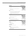
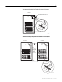
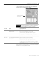
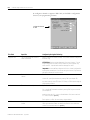
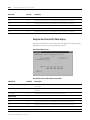
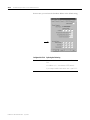
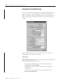
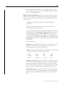
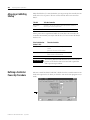
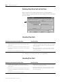
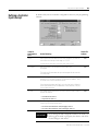
Use the keyswitch to change the mode in which a controller is operating.
If You Want to
Turn the Keyswitch to
• Run your program.
Outputs are enabled. (Equipment being controlled by the I/O RUN
addressed in the ladder program begins operation.)
PROG
• Force I/O.
• Save your programs to a disk drive (during operation).
• Enable outputs.
R
E
M
RUN
• Edit data table values.
Notes:
• You cannot create or delete a program file, create or delete
data files, edit online, or change the modes of operation
through the programming software while in run mode.
• You can prevent forcing and data table changes by
usingRSLogix5 programming software to set user control bit
S:26/6.
• Disable outputs (outputs are turned off).
• Create, modify, and delete ladder files, SFC files, or data
files.
PROG (program)
PROG
• Download to/from a memory module.
R
E
M
• Save/restore programs.
Notes:
RUN
• The controller does not scan the program.
• You cannot change the mode of operation through the
programming software while in program mode.
Change between remote program, remote test, and remote run
modes through the programming software.
Remote run
REM (remote)
PROG
• Enable outputs.
R
E
M
• Save/restore programs.
• Edit while operating.
RUN
Remote program
See the program-mode description above.
Remote test
• Execute ladder programs with outputs disabled.
• Cannot create or delete ladder programs or data files.
• Save/restore programs.
• Edit while operating.
Publication 1785-UM012D-EN-P - July 2005
1-10
Understanding Your Programmable Controller
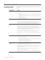
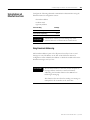
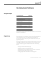
Programming Features
This table highlights the programming features of a PLC-5 programmable
controller.
This Capability
Ladder logic
Lets You
program using a language that is representative of relay logic.
Choose this language
Subroutines
Sequential Function Charts
(SFCs)
• if you are more familiar with ladder logic than with programming languages such
as BASIC
Your plant personnel may be more familiar with ladder logic; consider their needs
as well.
• performing diagnostics
• programming discrete control
store recurring sections of program logic that can be accessed from multiple program
files.
A subroutine saves memory because you program repetitive logic only once. The JSR
instruction directs the controller to go to a separate subroutine file within the logic
controller, scan that subroutine file once, and return to the point of departure.
use sequence-control language to control and display the state of a sequential process.
Instead of using one long ladder program for your application, divide the logic into steps
and transitions. A step corresponds to a control task; a transition corresponds to a
condition that must occur before the programmable controller can perform the next
control task. The display of these steps and transitions lets you see what state the
machine process is in at a given time via a flowchart form.
SFCs offer constructs that enable execution of multiple paths of logic, or a single
selected path of logic, as well as the ability to jump forwards and backwards.
Troubleshooting can be reduced to a small routine of logic instead of an entire ladder
file.
Structured text
SFCs are best for defining the order of events in a sequential process.
program using a language similar to BASIC.
Choose structured text if you are:
Main Control Programs
(MCPs)
• more familiar with programming languages such as BASIC than with ladder logic
• using complex mathematical algorithms
• using program constructs that repeat or “loop”
• creating custom data-table monitoring screens
separate sequential logic from ladder logic and structured text as a way of modularized
your process and making troubleshooting easier.
Use several main control programs (MCPs) to define one main control program for each
particular machine or function of your process. MCPs accommodate independent or
non-sequential activities.
A main control program can be an SFC file numbered 1-999 or a ladder-logic file or
structured-text program numbered 2-999.
One data table is used by all MCPs (i.e., you do not have a separate data table for each
MCP).
Publication 1785-UM012D-EN-P - July 2005
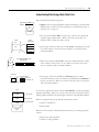
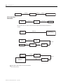
Understanding Your Programmable Controller
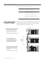
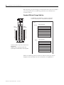
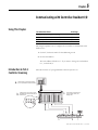
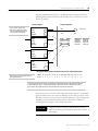
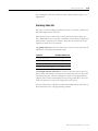
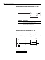
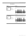
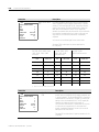
Using a Controller Channel
as a Remote I/O Scanner
1-11
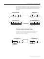
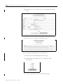
Configure a remote I/O channel for scanner mode to read and write I/O
information between a controller and an I/O device remotely located from the
controller.
PLC-5/40
A controller with a channel configured for scanner mode
acts as a supervisory controller for other controllers that
are in adapter mode as well as remote I/O adapter modules.
The scanner-mode PLC-5 controller can:
gather data from node adapter devices in remote I/O racks
process I/O data from 8-, 16-, or 32-point I/O modules
address I/O in 2-, 1-, or 1/2-slot I/O groups
support a complementary I/O configuration
support block-transfer in any I/O chassis
1771-ASB
Remote I/O
Link Cable:
Belden 9463
PLC-5/20
The scanner-mode PLC-5 controller:
transfers discrete data and block-transfer data
to/from modules in remote I/O racks as well as
to/from controllers in adapter mode.
scans remote I/O buffers asynchronously to the
program scan.
updates the input/output image data table from
the remote I/O buffer(s) synchronously to the
program scan
PLC-5 data table
is updated
synchronously to
program scan
(at housekeeping).
PLC-5
Data Table
Output
Remote I/O buffers
are updated
asynchronously to
the program scan.
Controller
-resident
I/O
Input
Remote I/O
Buffer
Output
Input
Remote I/O
Link
Publication 1785-UM012D-EN-P - July 2005
1-12
Understanding Your Programmable Controller
A controller transfers I/O data and status data using:
• discrete
transfers
data transfers of 8 words per rack
occur automatically on the remote I/O network
• block-transfers special data transfers that require ladder logic
instructions to achieve the transfer
allow a transfer of a maximum of 64 words of data
also used to communicate information between a
scanner channel and an adapter-mode controller
channel
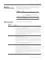
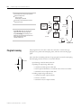
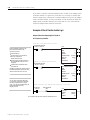
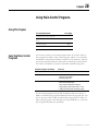
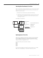
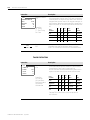
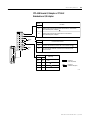
Using a Controller Channel
as a Remote I/O Adapter
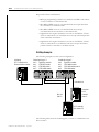
Configure a controller channel for adapter mode when you need predictable,
real-time exchange of data between a distributed control adapter-mode
controller channel and a supervisory controller. The remote I/O adapter
channel exchanges data with a supervisory controller.
PLC-5/40
In this example, a PLC-5/40 controller channel is
the supervisory (scanner-mode) controller of the
1771-ASB module and the PLC-5/20 controller.
Connect the controllers via the remote I/O link.
1771-ASB
You can monitor status between the
supervisory controller and the adapter-mode
PLC-5 controller channel at a consistent rate
(i.e., the transmission rate of the remote I/O link
is unaffected by programming terminals and
other non-control-related communications).
Remote I/O
Link Cable:
Belden 9463
PLC-5/20
The adapter-mode PLC-5 controller can monitor
and control its controller-resident local I/O while
communicating with the supervisory controller via
a remote I/O link.
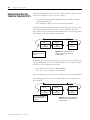
Publication 1785-UM012D-EN-P - July 2005
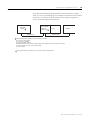
Understanding Your Programmable Controller
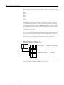
1-13
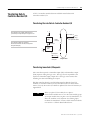
For Enhanced and Ethernet programmable controller channels in adapter
mode, you do not need ladder logic in the adapter controller for block-transfer
instructions. You define the block-transfers via an adapter configuration
screen and by defining block-transfer files.
PLC-5 controller
channel in
adapter mode 2
Supervisory
Controller 1
Remote I/O Link
1771 I/O
PanelView
Remote I/O Link
1 The following programmable controllers can operate as supervisory controllers:
PLC-2/20 and PLC-2/30 controllers
PLC-3 and PLC-3/10 controllers
PLC-5/15 and PLC-5/25E controllers
All Enhanced and Ethernet PLC-5 controllers; separate channels can be configured for a remote I/O scanner and an adapter
PLC-5/V30, PLC-5/V40, PLC-5/V40L, and PLC-5/V80 controllers
PLC-5/250 controllers
2 All PLC-5 family controllers, except the PLC-5/10, can operate as remote I/O adapter modules
Publication 1785-UM012D-EN-P - July 2005
1-14
Understanding Your Programmable Controller
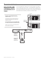
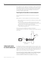
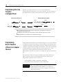
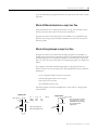
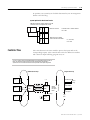
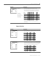
Using a PLC-5/40L, -5/60L
Programmable Controller
as an Extended-Local I/O
Scanner
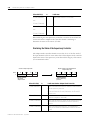
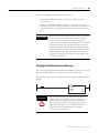
Use the extended-local I/O link when you need I/O updates more quickly
than is possible from remote I/O link. An extended-local I/O link provides
faster scan and update time than a remote I/O link. The extended-local I/O
link is limited to 30.5 cable-m (100 cable-ft). If an I/O chassis is located more
than 30.5m from the controller, you must use a remote I/O link.
PLC-5/60L
A PLC-5/40L or -5/60L controller (channel 2) and an
extended-local I/O adapter module (1771-ALX) form an
extended-local I/O link.
The extended-local I/O link is a parallel link that enables a
PLC-5/40L or -5/60L controller to scan a maximum of 16
extended-local I/O chassis.
Extended-local
I/O Link Cable:
1771-CXx
Due to the cabling design, you can remove an adapter module
from a chassis on the extended-local I/O link without disrupting
communication to other chassis on the extended-local I/O link.
1771-ALX
Important: The PLC-5/40L and -5/60L controllers cannot be
used as extended-local I/O adapters.
ExtendedLocal
I/O Link
Input
Output
PLC-5 data table
is updated
synchronously to
program scan
(at housekeeping).
Remote I/O buffers
are updated
asynchronously to
the program scan.
Publication 1785-UM012D-EN-P - July 2005
PLC-5 data table
Input
Output
Remote
I/O
Buffer
Input
Output
Remote I/O
Link
Input
Output
ControllerResident
Local I/O
Chapter
2
Selecting and Placing I/O
Using This Chapter
For Information About
Selecting I/O modules
Selecting I/O module density
Placing I/O modules in a chassis
Selecting I/O Modules
Go to Page
2-1
2-2
2-3
Select I/O modules to interface your PLC-5 controller with machines or
processes that you determine while analyzing your plant operation.
Use the following list and table as guidelines for selecting I/O modules and
operator control interface(s).
• How much I/O is required to control your process(es)?
• Where will you concentrate I/O points for portions of an entire process
when the entire process is distributed over a large physical area?
• What type of I/O is required to control your process(es)?
• What is the required voltage range for each I/O module?
• What is the backplane current required for each I/O module?
• What are the noise and distance limitations for each I/O module?
• What isolation is required for each I/O module?
1
Publication 1785-UM012D-EN-P - July 2005
2-2
Selecting and Placing I/O
Guidelines for Selecting I/O Modules
Choose this Type of
I/O Module
For these Types of Field Devices or Operations
(examples)
Discrete input module
and block I/O module
Selector switches, pushbuttons, photoelectric eyes, limit
switches, circuit breakers, proximity switches, level
switches, motor starter contacts, relay contacts,
thumbwheel switches
Input modules sense on/off or opened/closed
signals. Discrete signals can be either ac or dc.
Discrete output module
and block I/O module
Alarms, control relays, fans, lights, horns, valves, motor
starter, or solenoids
Output module signals interface with on/off or
opened/closed devices. Discrete signals can be
either ac or dc.
Analog input module
Temperature transducers, pressure transducers, load cell
transducers, humidity transducers, flow transducers, and
potentiometers
Convert continuous analog signals into input values
for the PLC controller.
Analog output module
Analog valves, actuators, chart recorders, electric motor
drives, analog meters
Interpret PLC controller output to analog signals
(generally through transducers) for field devices.
Specialty I/O modules
Encoders, flow meters, I/O communication, ASCII, RF type
devices, weigh scales, bar-code readers, tag readers,
display devices
Are generally used for specific applications such as
position control, PID, and external device
communication.
Selecting I/O Module
Density
Explanation
The density of an I/O module is the number of controller input or output
image-table bits to which it corresponds. A bidirectional module with 8 input
bits and 8 output bits has a density of 8. I/O module density helps determine
your I/O addressing scheme. See chapter 4 for more information about I/O
addressing.
Use these guidelines for selecting I/O module density:
Choose this I/O Density If You
8-point I/O module
• currently use 8-point modules
• need integral, separately-fused outputs
16-point I/O module
• want to minimize cost per module
• currently use 16-point modules
32-point I/O module
• need separately-fused outputs with a special
wiring arm
• currently use 32-point modules
• want to minimize number of modules
• want to minimize the space required for I/O
chassis
• want to minimize cost per I/O point
Publication 1785-UM012D-EN-P - July 2005
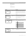
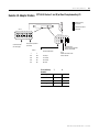
Selecting and Placing I/O
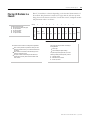
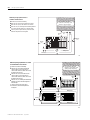
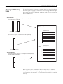
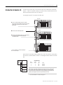
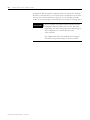
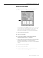
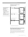
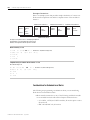
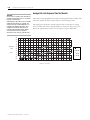
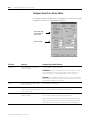
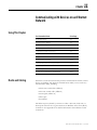
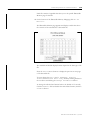
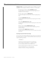
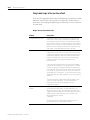
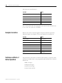
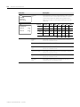
Placing I/O Modules in a
Chassis
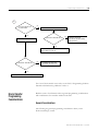
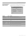
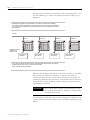
Place I/O modules in a chassis depending on the electrical characteristics of
the module. The placement is made left to right, with the left-most position
being closest in the chassis to the PLC-5 controller or the I/O adapter module.
The placement order is as follows:
Priority:
Module placement priority:
1. block-transfer modules (all types)
2. dc input modules
3. dc output modules
4. ac input modules
5. ac output modules
2-3
P
L
C
/
A
S
B
1
1
2
2
3
Block
Block
dc
dc
Transfer Transfer input input
3
dc
dc
output output
4
4
5
ac
input
ac
input
ac
ac
output output
lowV
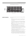
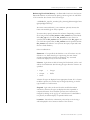
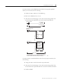
Place block-transfer modules according to these guidelines:
Place as many modules as possible for which you need
fast block-transfer times in your controller-resident local
I/O chassis.
Place modules in which block-transfer timing is not as
critical in remote I/O chassis.
Ac output modules should always be the furthest I/O
modules away from any block-transfer modules in the
same chassis.
5
empty
highV
Place input and output modules according to
these guidelines:
left to right
lowest voltage to highest voltage
For optimal speed using discrete I/O, use the
following module-placement priority scheme:
1. controller chassis
2. extended-local I/O chassis
3. remote I/O chassis
Publication 1785-UM012D-EN-P - July 2005
2-4
Selecting and Placing I/O
Notes
Publication 1785-UM012D-EN-P - July 2005
Chapter
3
Placing System Hardware
Using This Chapter
For Information About
Determining the proper environment
Protecting your controller
Avoiding electrostatic damage
Laying out your cable raceway
Laying out your backpanel spacing
Grounding your system
Determining the Proper
Environment
Go to Page
3-1
3-3
3-3
3-4
3-5
3-6
Place the controller in an environment with conditions that fall within these
guidelines:
Environmental Condition
Operating temperature
Storage temperature
Relative humidity
Acceptable Range
0 to 60° C (32 to 140° F)
-40 to 85° C (-40 to 185° F)
5 to 95% (without condensation)
Separate your programmable controller system from other equipment and
plant walls to allow for convection cooling. Convection cooling draws a
vertical column of air upward over the controller. This cooling air must not
exceed 60° C (140° F) at any point immediately below the controller. If the air
temperature exceeds 60° C, install fans that bring in filtered air or recirculate
internal air inside the enclosure, or install air-conditioning/heat-exchanger
units.
To allow for proper convection cooling in enclosures containing a
controller-resident chassis and remote I/O chassis, follow these guidelines.
1
Publication 1785-UM012D-EN-P - July 2005
3-2
Placing System Hardware
Minimum spacing requirements for a
controller-resident chassis:
Mount the I/O chassis horizontally.
Allow 153 mm (6 in) above and below the chassis.
Allow 102 mm (4 in) on the sides of each chassis.
Allow 51 mm (2 in) vertically and horizontally between
any chassis and the wiring duct or terminal strips.
Leave any excess space at the top of the enclosure,
where the temperature is the highest.
Area reserved for disconnect,
transformer, control relays, motor
starters, or other user devices.
153mm
(6")
51mm
(2")
102mm
(4")
102mm
(4")
153mm
(6")
51mm(2")
Wiring Duct
13081
Minimum spacing requirements for a remote
I/O and extended-local I/O chassis:
Mount the I/O chassis horizontally.
Allow 153 mm (6 in) above and below all
chassis. When you use more than one
chassis in the same area, allow 152.4 mm (6
in) between each chassis.
Allow 102 mm (4 in) on the sides of each
chassis. When you use more than one
chassis in the same area, allow 101.6 mm (4
in) between each chassis.
Allow 51 mm (2 in) vertically and horizontally
between any chassis and the wiring duct or
terminal strips.
Leave any excess space at the top of
the enclosure, where the temperature is
the highest.
Area reserved for disconnect,
transformer, control relays, motor
starters, or other user devices.
102mm
(4")
153mm
(6")
51mm (2")
153mm (6")
Wiring Duct
51mm (2")
102mm
(4")
102mm
(4")
153mm (6")
Wiring Duct
18749
Publication 1785-UM012D-EN-P - July 2005
Placing System Hardware
Protecting Your Controller
3-3
You provide the enclosure for your controller system. This enclosure protects
your controller system from atmospheric contaminants such as oil, moisture,
dust, corrosive vapors, or other harmful airborne substances. To help guard
against electromagnetic interference (EMI) and radio frequency interference
(RFI), we recommend a steel enclosure.
Mount the enclosure in a position where you can fully open the doors. You
need easy access to controller wiring and related components so that
troubleshooting is convenient.
When you choose the enclosure size, allow extra space for transformers,
fusing, disconnect switch, master control relay, and terminal strips.
Preventing Electrostatic
Discharge
ATTENTION
Under some conditions, electrostatic discharge can degrade
performance or damage the controller. Read and observe
the following precautions to guard against electrostatic
damage.ESD protection
• Wear an approved wrist strap grounding device when
handling the controller.
• Touch a grounded object to discharge yourself before
handling the controller.
• Do not touch the backplane connector or connector
pins.
Publication 1785-UM012D-EN-P - July 2005
3-4
Placing System Hardware
Laying Out Your Cable
Raceway
The raceway layout of a system reflects where the different types of I/O
modules are placed in I/O chassis. Therefore, you should determine
I/O-module placement prior to any layout and routing of wires. When
planning your I/O-module placement, however, segregate the modules based
on the conductor categories published for each I/O module so that you can
follow these guidelines. These guidelines coincide with the guidelines for “the
installation of electrical equipment to minimize electrical noise inputs to
controllers from external sources” in IEEE standard 518-1982.
To plan a raceway layout, do the following:
• categorize conductor cables
• route conductor cables
Categorize Conductors
Segregate all wires and cables into categories as described in the Industrial
Automation Wiring and Grounding Guidelines, publication 1770-4.1. See the
installation data for each I/O module that you are using for information about
its classification.
Route Conductors
To guard against coupling noise from one conductor to another, follow the
general guidelines for routing cables described in the Industrial Automation
Wiring and Grounding Guidelines, publication 1770-4.1. You should follow
the safe grounding and wiring practices called out in the National Electrical
Code (NEC, published by the National Fire Protection Association, in Quincy,
Massachusetts), and local electrical codes.
Publication 1785-UM012D-EN-P - July 2005
Placing System Hardware
3-5
Use 6.35 mm (0.25 inch) mounting bolts to attach the I/O chassis to the
enclosure backpanel.
Laying Out Your
Backpanel Spacing
Chassis Dimensions (Series B)
1771-A1B
1771-A2B
1771-A3B1
1771-A4B
591mm
(23.25")
16-slot 1771
464mm
(18.25")
337mm
(13.25")
193mm
(7.60")
Side
12-slot
8-slot
210mm
(8.25")
315mm
(12.41")
4-slot
254mm
(10")
Power
C onnector
171mm
(6.75")
483mm
(19.01")
229mm
(9.01")
610mm
(24.01")
16-slot 1771-A4B
12-slot 1771-A3B1
356mm
(14.01")
8-slot 1771-A2B
4-slot 1771-A1B
1771-A3B
217mm 1
(8.54")
465mm
(18.31")
484mm
(19")
9mm
(.34")
26mm
(1.02")
178mm
(7")
Side
339mm
(13.53")
Front
130mm
(5.10")
12450-I
1 Total maximum depth dimension per installation will be dependent upon module wiring and connectors.
Publication 1785-UM012D-EN-P - July 2005
3-6
Placing System Hardware
I/O Chassis and External Power Supply Dimensions
U se .25" dia
mounting bolts
(4 places)
315mm
(12.41")
16-slot
591mm
(23.25")
464mm
(18.25")
337mm
(13.25")
210mm
(8.25")
External
Power
Supply
91mm
(3.6")
483mm
(19.01")
610mm
(24.01")
4-slot
16-slot 1771-A4B
12-slot 1771-A3B1
356mm
(14.01")
Clearance depth is 204mm (8") for 8 I/O connection points per module.
Publication 1785-UM012D-EN-P - July 2005
8-slot
254mm
(10")
229mm
(9.01")
Grounding Your System
12-slot
8-slot 1771-A2B
4-slot 1771-A1B
12451-I
For more information on proper grounding guidelines, see the Industrial
Automation Wiring and Grounding Guidelines, publication 1770-4.1.
Placing System Hardware
3-7
Recommended Grounding Configuration for Remote I/O Systems
Enclosure
Grounding Electrode Conductor
Ground
Bus
To Grounding
Electrode
System
I/O Chassis Wall
Ground
Lug
Nut
Star
Washer
Ground Lug
15561
Required Grounding Configuration for Extended-Local I/O Systems
Enclosure
Enclosure
Ground
Bus
Ground
Bus
To
Grounding
Electrode
System
(single
point only)
Extended-Local I/O Cables
I/O Chassis
Wall
I/O Chassis
Ground Stud
Ground
Lug
Nut
Star
Washer
Ground Lug
18585
Publication 1785-UM012D-EN-P - July 2005
3-8
Placing System Hardware
Notes
Publication 1785-UM012D-EN-P - July 2005
Chapter
4
Addressing I/O and Controller Memory
Using This Chapter
For Information About
I/O addressing concept
Choosing an addressing mode
Addressing block-transfer modules
Addressing summary
Assigning racks
Understanding PLC-5 controller memory
Addressing
Effectively Using I/O Memory
I/O Addressing Concept
Go to Page
4-1
4-3
4-7
4-7
4-8
4-10
4-16
4-24
Since the main purpose of a programmable controller is to control inputs and
outputs of field devices like switches, valves, and thermocouples, these inputs
and outputs must occupy a location in the controller memory so that they can
be addressed in your control program. Each terminal on an input or output
module that can be wired to a field device occupies a bit within controller
memory. The part of controller memory that houses I/O addresses is the
input image table and the output image table.
I/O addressing helps connect the physical location of an I/O module terminal
to a bit location in the controller memory. I/O addressing is just a way to
segment controller memory. The segmentation is as follows:
Classification
Term
Relation to Controller Memory
A specific terminal on an I/O module that
occupies a space in controller memory
terminal or
point
The density of an I/O module, i.e., 8-point, 16-point, 32-point, directly
relates to the amount of memory (bits) the module occupies in controller
memory. For example, a 16-point input module occupies 16 bits in the
controller’s input image table.
I/O terminals that when combined occupy 1
word in controller’s input image table and 1
word in the controller’s output image table.
I/O group
16 input bits = 1 word in controller’s input image table
16 output bits = 1 word in the controller’s output image table
Controller memory needs to be grouped so that I/O rack
related I/O groups can be considered a unit.
128 input bits and 128 output bits, or8 input words and 8 output words,
or 8 I/O groups
Each PLC-5 controller has a finite amount of racks it can support. For
example, a PLC-5/30 can support 8 I/O racks.
The controller always occupies at least one I/O rack for itself, rack 0 by
default.
1
Publication 1785-UM012D-EN-P - July 2005
4-2
Addressing I/O and Controller Memory
The figure below shows the relationship between an I/O terminal and its
location in controller memory.
I/O Addressing as It Relates to an I/O Terminal
rack number 01
I/O group number 4
rack number 01
I/O group number 5
word
address
17 16 15 14 13 12 11 10 07 06 05 04 03 02 01 00
00
Output Image Table
A
B
C
D
00
01
02
03
04
05
06
07
10
11
12
13
14
15
16
17
E
17 16 15 14 13 12 11 10 07 06 05 04 03 02 01 00
A
B
C
D
00
01
02
03
04
05
06
07
10
11
12
13
14
15
16
17
E
05
07
00
Input Image Table
04
17 16 15 14 13 12 11 10 07 06 05 04 03 02 01 00
Input Module
(1771-IAD)
04
Output Module
(1771-OAD)
07
I:014
O:015
| |
( )
07
12
I:014/12
I for input or O for output
Notice how input and output
image file addresses
correspond to hardware.
2-digit I/O rack number
I/O group number (0-7)
input or output number (0-7,10-17) (bit)
I/O image table is
addressed octally.
Now that you are familiar with how controller memory is segmented to
address a specific I/O terminal, the next section explains available addressing
modes. These modes let you define the relationship between an I/O chassis
slot and an I/O group (16 input bits and 16 output bits).
Publication 1785-UM012D-EN-P - July 2005
Addressing I/O and Controller Memory
Choosing an Addressing
Mode
4-3
For each I/O chassis in your system, you must define how many I/O chassis
slots make up an I/O group (1 word each in the input image table and output
image table); this choice is the chassis’ addressing mode. Choose from among
these available modes:
2-slot addressing
2 I/O chassis slots = 1 I/O group = 1 input image word and 1 output image
word = 16 input bits and 16 output bits.
Controller memory
Rack x
Output Image Table
16 bits input
Word #
16 bits output
x
1-slot addressing
1 I/O chassis slot = 1 I/O group = 1 input image word and 1 output image
word = 16 input bits and 16 output bits.
x
x
x
x
x
x
x
Input Image Table
Word #
x
x
16 bits input and 16 bits output
x
x
1/2-slot addressing
1/2 of an I/O chassis slot = 1 I/O group = 1 input image word and 1 output image
word = 16 input bits and 16 output bits.
x
x
x
x
16 bits input and 16 bits output
When you place your I/O modules in the I/O chassis slots, the module’s
density determines how quickly I/O groups form. For example, let’s choose
1-slot addressing and see how 8-, 16-, and 32-point I/O modules fill controller
memory.
Publication 1785-UM012D-EN-P - July 2005
4-4
Addressing I/O and Controller Memory
18-and 16-point Example
1-slot addressing (1 I/O chassis slot = 1 I/O group = 1 input image
word and 1 output image word = 16 input bits and 16 output bits.)
23
01
Controller memory
Rack x
Output Image Table
Word #
0
1
2
Input
Terminals
00
01
02
03
04
05
06
07
Input
Termi
nals 10
11
12
13
14
15
16
17
Input
Terminals
00
01
02
03
04
05
06
07
Input
Terminals
3
4
00
01
02
03
04
05
06
07
3
5
6
4
7
17
00
bits
Input Image Table
Word #
1
Group 2
Group 0
0
1
Group 3
2
An 8-point I/O module occupies
8 bits in a word. See 1
Two 8-point input modules occupy 8
bits of each group. See 2
2
3
3
4
5
4
45
6
7
67
17
Input
Terminals
Input
Terminals
00
01
02
03
04
05
06
07
Group 4
Output
Terminals
00
01
02
03
04
05
06
07
Group 5
An 8-point input module in group 4
occupies the first eight bits of input
word 4. The 8 point output module
occupies the first 8-output bits in
output word 5. See 3
Publication 1785-UM012D-EN-P - July 2005
Output
Terminals
00
01
02
03
04
05
06
07
10
11
12
13
14
15
16
17
00
01
02
03
04
05
06
07
10
11
12
13
14
15
16
17
Group 6
00
Group 7
16-point I/O modules occupy 16 bits,
an entire word, in the image table.
See 4
If you were to address the device attached to
this output circuit in your control program, the
address would be O:xx7/17.
bits
Addressing I/O and Controller Memory
4-5
32-point Example
1-slot addressing (1 I/O chassis slot = 1 I/O group = 1 input image
word and 1 output image word = 16 input bits and 16 output bits.)
01
32-point input module
Controller memory
Rack x
Output Image Table
Word #
0
32-point I/O modules use the entire word
of their group and borrow the entire word
of the next group. See 1 .
Since the module is in group 0 and the
inputs for group 0 and group 1 are used,
you must:
install an output module in group 1
or leave the slot empty
1
1
2
3
4
5
6
7
17
00
bits
Input Image Table
Word #
Group 0
0
2
1
2
01
32-point input module
3
32-point output module
4
5
6
7
17
00
bits
Since the input image table for group 1 is unavailable because it is
being used by the input module of group 0, installing a 32-point output
module makes use of output image table of group 0 and 1. See 2 .
You can also install 8- or 16-point output modules. But you cannot
install another input module since all the input image space for groups
0 and 1 are used by the input module of group 0.
Group 0
Group 1
Publication 1785-UM012D-EN-P - July 2005
4-6
Addressing I/O and Controller Memory
When planning your system design, consider the densities of the I/O modules
you are using and choose an addressing mode that most efficiently uses
controller memory.
Example of Efficient I/O Image Table Use.
2-slot addressing (2 I/O chassis slot = 1 I/O group = 1 input image
word and 1 output image word = 16 input bits and 16 output bits.)
Controller memory
Rack x
Output Image Table
Word #
Output
Terminals
Input
Terminals
00
01
02
03
04
05
06
07
10
11
12
13
14
15
16
17
00
01
02
03
04
05
06
07
10
11
12
13
14
15
16
17
0
1
2
3
4
5
6
7
17
00
bits
Input Image Table
Word #
0
1
Group 0
2
16-point I/O modules occupy 16 bits, an entire word, in
the image table.
Installing as a pair a 16-point input module and a
16-point output module efficiently uses the image table.
3
4
5
6
7
17
00
bits
Define the addressing mode for each I/O chassis by setting the chassis
backplane switch assembly. For more information, see Appendix E.
Publication 1785-UM012D-EN-P - July 2005
Addressing I/O and Controller Memory
Addressing
Block-Transfer Modules
4-7
Block-transfer modules occupy 8 bits in the controller’s I/O image table.
Since all block-transfer modules are bidirectional, they cannot be used to
complement either input or output modules.
To Address
Use
single slot modules assigned I/O rack and group number of the slot in which the
module resides and 0 for the module number
When using 1/2-slot addressing, use the assigned rack
number and the lowest group number and 0 for the module
number.
double-slot modules assigned rack number and the lowest group number and 0 for
the module number
Addressing Summary
Addressing
Mode
2-slot
1-slot
1/2-slot
Use this table as a quick reference for addressing.
Guidelines
• Two I/O module slots = 1 group
• Each physical 2-slot I/O group corresponds to one word (16 bits) in the input image table and
one word (16 bits) in the output image table
• When you use 16-point I/O modules, you must install as a pair an input module and an output
module in an I/O group; if you use an input module in slot 0, you must use an output module in
slot 1 (or it must be empty). This configuration gives you the maximum use of I/O.
• You cannot use a block-transfer module and a 16-point module in the same I/O group because
block-transfer modules use 8 bits in both the input and output table. Therefore, 8 bits of the
16-point module would conflict with the block-transfer module.
• You cannot use 32-point I/O modules.
• Assign one I/O rack number to eight I/O groups.
• One I/O module slot = 1 group
• Each physical slot in the chassis corresponds to one word (16 bits) in the input image table and
one word (16 bits) in the output image table
• When you use 32-point I/O modules, you must install as a pair an input module and an output
module in an even/odd pair of adjacent I/O group; if you use an input module in slot 0, you must
use an output module in slot 1 (or it must be empty). This configuration gives you the maximum
use of I/O.
• Use any mix of 8- and 16-point I/O modules, block-transfer or intelligent modules in a single I/O
chassis. Using 8-point modules results in fewer total I/O.
• Assign one I/O rack number to eight I/O groups.
• One half of an I/O module slot = 1 group
• Each physical slot in the chassis corresponds to two words (32 bits) in the input image table
and two words (32 bits) in the output image table
• Use any mix of 8-, 16-, and 32-point I/O or block-transfer and intelligent modules. Using 8-point
and 16-point I/O modules results in fewer total I/O.
• With the controller-resident local rack set for 1/2-slot addressing, you cannot force the input
bits for the upper word of any slot that is empty or that has an 8-point or 16-point I/O module.
For example, if you have an 8-point or a 16-point I/O module in the first slot of your local rack
(words 0 and 1 of the I/O image table, 1/2-slot addressing), you cannot force the input bits for
word 1 (I:001) on or off.
• Assign one I/O rack number to eight I/O groups.
Publication 1785-UM012D-EN-P - July 2005
4-8
Addressing I/O and Controller Memory
Assigning Racks
The number of racks in a chassis depends on the chassis size and the
addressing mode:
If Using this
Chassis Size
4-slot
8-slot
12-slot
16-slot
2-slot Addressing,
Results In
1/4 rack
1/2 rack
3/4 rack
1 rack
Group together 1/4 racks
and 1/2 racks
Publication 1785-UM012D-EN-P - July 2005
1
1
1
2
2
2
3
17
1/2-slot Addressing,
Results In
1 rack
2 racks
3 racks
4 racks
When assigning rack numbers, use the following guidelines:
TIP
Rack
Address
1-slot Addressing,
Results In
1/2 rack
1 rack
1-1/2 racks
2 racks
• One I/O rack number is eight I/O groups, regardless of
the addressing mode that you select.
• You can assign from one to four racks in your
controller-resident local chassis (128 inputs and 128
outputs) depending on the chassis size and addressing
mode. You cannot split a controller-resident local I/O
rack over two or more chassis or assign unused
controller-resident local I/O groups to remote I/O racks.
• The default address of the controller-resident local rack is
0.
• You cannot split racks across remote I/O and
extended-local I/O links. For example, if an 8-slot
extended-local I/O chassis is configured as I/O groups
0-3 of I/O rack 2, an 8-slot remote I/O chassis cannot be
configured as I/O groups 4-7 of I/O rack 2. For more
information about addressing extended-local I/O, see
chapter 8.
• When using complementary I/O addressing, treat
complementary rack addresses individually when
grouping racks; primary rack numbers are separate from
complement rack numbers.
• If you are not using the autoconfiguration function, group
together 1/4-racks and 1/2-racks of each logical rack on
the configuration screen of your programming software.
Do not intersperse these with other rack numbers. For
example, your programming software has a screen with
the following information for defining racks:
Starting
Group
0
2
4
0
2
4
0
0
Rack
Size
1/4
1/4
1/4
1/4
1/4
1/2
1/4
FULL
Range
010-011
012-013
014-015
020-021
022-023
024-027
030-031
170-177
Fault
Inhibit
I
0
0
0
0
0
0
0
Reset
0
0
0
0
0
0
0
0
Retry
0
0
0
0
0
0
0
0
Addressing I/O and Controller Memory
4-9
When assigning remote I/O rack numbers, use these
guidelines:
TIP
• A single remote I/O scanner channel can support up to 32 devices
but only 16 rack numbers. For more information, see chapter 6.
• Limit the number of remote I/O rack numbers to those that your
PLC-5 controller can support.
• The PLC-5 controller and the 1771-ASB adapter module
automatically allocate the next higher rack number(s) to the
remaining I/O groups of the chassis. For example, if you select
1/2-slot addressing for your controller-resident local chassis and
you are using a 16-slot (1771-A4B) chassis, the controller will
address racks 0, 1, 2, and 3 in this chassis.
• You can assign a remote I/O rack to a fraction of a chassis, a
single I/O chassis, or multiple I/O chassis as shown below.
I/O Rack No. 0
I/O Rack No. 1
01 23 45 67 01 23 45 67
0
1
2
3
4 5
6
7
One 16-slot chassis, two racks
One 16-slot chassis, one rack
I/O Rack No. 3
0
1
2
3
One 8-slot chassis, 1/2 rack
4
5
Two 4-slot chassis, 1/4 rack each
6
7
16466
Publication 1785-UM012D-EN-P - July 2005
4-10
Addressing I/O and Controller Memory
Understanding PLC-5
Controller Memory
Controller memory is divided into two basic areas:
Storage Areas
Description
Data
All of the data the controller examines or changes is stored in files in data
storage areas of memory. These storage areas store:
• Data received from input modules
• Data to be sent to output modules; this data represents decisions made
by the logic
• Intermediate results made by the logic
• Preloaded data such as presets and recipes
• Control instructions
• System status
You create files for program logic, depending on the method you are using:
ladder logic, sequential function charts, and/or structured text. These files
contain the instructions to examine inputs and outputs and return results.
Program Files
Publication 1785-UM012D-EN-P - July 2005
Addressing I/O and Controller Memory
4-11
Understanding Data Storage (Data-Table Files)
The controller divides data storage into:
Integer Data
Table Files
File #
Integer
File 7
• Types that let you specify different formats and ranges to accommodate
different types of data. For more information on the different types of
data files, see on page 13.
File 999
Words
(Sample Data)
Integer
Files
• You can create multiple files of a given type. Files let you group and
organize logically related data. When you need to access data, you
specify the file in which the data is stored.
1020
File 7
64
7779
2
Integer
File
Natural binary bit pattern for 276
(decimal format)
276
0 0 0 0 0 0 01 0 0 0 1 0 1 0 0
• Some types of files are made up of 16-bit words. Floating-point words
are 32 bits. When you need to access this data, you specify it with a
formatted address.
• Each word contains multiple bits. This is the smallest division of data.
A bit contains a value of zero or one. When you need to access this
data, you specify it with a formatted address.
Timer File #
structure members
2760 preset .PRE
accumulated .ACC
432
Timer #
.EN .TT .DN
File #
Starting addr
(Length)
recipe "A" data
Starting addr
(Length)
recipe "B" data
Starting addr
(Length)
production counts
up to 1000
words
• Some types of files are divided into structures used to control
instruction elements. These structures are subdivided into members at
the bit or word level. When you need to access this data, you specify it
with a formatted address.
You can also organize data within files into data blocks to group and organize
logically related data. When you need to access this data, you specify only the
starting address within the file (and length) instead of each individual address.
When you organize data, group data by similar kind, such as:
• results of calculations
• batch recipes
Because of the structure of block-transfer instructions, you must group data
such as:
• inputs from analog modules
• outputs to analog modules
Publication 1785-UM012D-EN-P - July 2005
4-12
Addressing I/O and Controller Memory
TIP
You might also want to leave room for future expansion
when grouping data. Do this by leaving gaps between:
• data blocks within a file
• groups of sequentially numbered files
• modules in an I/O chassis
IMPORTANT
TIP
If you plan to edit your program online in Run mode, you
must allocate unused data table files/elements and program
files because you cannot create user memory while in run
mode. Each unused file, however, uses 6 words of overhead
memory for each data/program file you skip. Use care
when leaving gaps.
Follow these guidelines when organizing data files:
• Group large amounts of related data into files.
• Address the data files from 3-999 as needed.
(See on page page 13).
• Address the words needed in each data file
consecutively from 0-999 (0-1999 for some data types
in series E, revision D controllers and later).
• Address the words of I/O image data according to how
you configured your I/O:
– 0-37 (octal) for PLC-5/11, -5/20, -5/20E
– 0-77 (octal) for PLC-5/30
– 0-177 (octal) for PLC-5/40, -5/40L, -5/40E
– 0-277 (octal) for PLC-5/60, -5/60L, -5/80, -5/80E
• When addressing I/O image bits, address them 00-07
or 10-17 (octal).
• When organizing bit data, address the bits in each word
0-15 (decimal) for binary or integer files.
Each data table file allocates 6 words of memory when you
create the file. This is in addition to any data stored in the
file.
Publication 1785-UM012D-EN-P - July 2005
Addressing I/O and Controller Memory
4-13
Addressing File Types
The following two tables show the available file types and the amount of
memory used by each.
Data Table File Types and Memory Usage for PLC-5 Controllers Series E/Revision D
and Later
File Type
File-Type File
Maximum Size of File
Identifier Number 16-bit Words and Structures
PLC-5/11,
-5/20,
-5/20E
PLC-5/30 PLC-5/40,
-5/40E,
-5/40L
PLC-5/60,
-5/60L,
-5/80, -5/80E
Memory Used in
Overhead for Each
File
(in 16-bit Words)
Memory Used
(in 16-bit Words)
per Word,
Character, or
Structure
Output image O
0
32
64
128
192
6
1/word
Input image
I
1
32
64
128
192
6
1/word
Status
S
2
128
128
128
128
6
1/word
Bit (binary)
B
31
2000 words
6
1/word
Timer
T
41
6000 words/2000 structures
6
3/structure
Counter
C
51
6000 words/2000 structures
6
3/structure
Control
R
61
6000 words/2000 structures
6
3/structure
Integer
N
71
2000 words
6
1/word
Floating-point F
81
4000 words/2000 structures
6
2/structure
ASCII
A
3-999
2000 words
6
1/2 per character
BCD
D
3-999
2000words
6
1/word
Block-transfer BT
3-999
12000 words/2000 structures
6
6/structure
Message
MG
3-999
32760 words/585 structures2
6
56/structure
PID
PD
3-999
32718 words/399 structures2
6
82/structure
SFC status
SC
3-999
6000 words/2000 structures
6
3/structure
ASCII string
ST
3-999
32760 words/780 structures2
6
42/structure
Unused
--
9-999
6
6
0
1
2
This is the default file number and type. For this file type, you can assign any file number from 3 through 999.
The maximum size of a data table file is 32K words. The maximum size of the entire data table is 64K words
Publication 1785-UM012D-EN-P - July 2005
4-14
Addressing I/O and Controller Memory
Data Table File Types and Memory Usage for PLC-5 Controllers Series E/Revision C
and Earlier
File Type
File-Type File
Maximum Size of File
Identifier Number 16-bit Words and Structures
PLC-5/11,
-5/20,
-5/20E
PLC-5/30 PLC-5/40,
-5/40E,
-5/40L
PLC-5/60,
-5/60L,
-5/80, -5/80E
Memory Used in
Overhead for Each
File
(in 16-bit Words)
Memory Used
(in 16-bit Words)
per Word,
Character, or
Structure
Output image O
0
32
64
128
192
6
1/word
Input image
I
1
32
64
128
192
6
1/word
Status
S
2
128
128
128
128
6
1/word
Bit (binary)
B
31
1000 words
6
1/word
Timer
T
41
3000 words/1000 structures
6
3/structure
Counter
C
51
3000 words/1000 structures
6
3/structure
Control
R
61
3000 words/1000 structures
6
3/structure
Integer
N
71
1000 words
6
1/word
Floating-point F
81
2000 words/1000 structures
6
2/structure
ASCII
A
3-999
1000 words
6
1/2 per character
BCD
D
3-999
1000words
6
1/word
Block-transfer BT
3-999
6000 words/1000 structures
6
6/structure
Message
MG
3-999
32760 words/585 structures2
6
56/structure
PID
PD
3-999
32718 words/399 structures2
6
82/structure
SFC status
SC
3-999
3000 words/1000 structures
6
3/structure
ASCII string
ST
3-999
32760 words/780 structures2
6
42/structure
Unused
--
9-999
6
6
0
1
2
This is the default file number and type. For this file type, you can assign any file number from 3 through 999.
The maximum size of a data table file is 32K words. The maximum size of the entire data table is 64K words
Publication 1785-UM012D-EN-P - July 2005
Addressing I/O and Controller Memory
4-15
Valid Data Types/Values Are:
This Data Type/Value
Immediate
(program constant)
Integer
Float
Block
Message
PID
String
SFC status
Accepts Any
Value between -32768 and 32767 (Constants greater than 1024 use 2 storage words of memory; floating point
constants use 3 words of memory.)
Integer data type: integer, timer, counter, status, bit, input, output, ASCII, BCD, control (e.g., N7:0, C4:0, etc.)
Floating point data type (valid range is + 1.175494e-38 to +3.402823e+38) with 7-digit precision
Block-transfer data type (e.g., BT14:0) or integer data type (e.g., N7:0)
Message data type (e.g., MG15:0) or integer data type (e.g., N7:0)
PID data type (e.g., PD16:0) or integer data type (e.g., N7:0)
String data type (e.g., ST12:0)
SFC status data type (e.g., SC17:0)
Understanding Program-File Storage
Create program files based on the programming method you are using. This
table lists the number of words used by each type of program file:
Program File
Ladder
SFC
Structured Text
Number of Words Used
6/file + 1/word
6/file
6/file + 1/word
The more program files that you create, the longer the controller takes to
perform certain tasks, e.g., going to run mode, performing online editing,
saving a program. Also, certain instructions (JMP, LBL, FOR, and NXT) have
longer execution times in higher program file numbers.
Series E PLC-5 controllers support 2000 program files to allow for more SFC
steps in your program. SFC step/transition program files are typically shorter
in length. This enhancement will effectively double your SFC step/transition
size.
Each program file you create is allocated 6 words of memory. This memory is
in addition to any programming within the file. If you create the maximum
program file number 1999, this allocates 12,000 words of memory to the
program files, which reduces the amount of controller memory left for
programming.
Publication 1785-UM012D-EN-P - July 2005
4-16
Addressing I/O and Controller Memory
Valid formats for addressing data files are:
Addressing
If You Want to Access
Input or output bit in the I/O image table
Bit, word, sub-member, data block, file, or I/O image bit
A component within a logical address by substituting the
value in another address
An address offset by some number of elements
A substitute name for an address
Use this Addressing Format
I/O image address
Logical address
Indirect address
And See Page
4-16
4-17
4-18
Indexed address
Symbolic address
4-20
4-21
For more information about entering addresses, see the documentation for
your programming software.
Specifying I/O Image Addresses
The I/O image address corresponds to the physical location of the I/O circuit
in the I/O chassis:
a
I/O address identifierI = input device
O = output device
bb
I/O Rack numberPLC-5/11, -5/20, -5/20E00-03 (octal)
PLC-5/3000-07 (octal)
PLC-5/40, -5/40L, -5/40E00-17 (octal)
PLC-5/60, -5/60L, -5/80, -5/80E00-27 (octal)
c
I/O Group number0-7 (octal)
dd
Terminal (bit) number00-17 (octal)
To Specify this
Address
Input Image Bit
Example
I
:
0
1
7
/
0
1
I for input
2-digit I/O rack Number
I/O group number (0-7)
Input number (0-7, 10-17)
Output Image Bit
O : 0 1 7 / 0 1
O for output
2-digit I/O rack Number
I/O group number (0-7)
Output number (0-7, 10-17)
Publication 1785-UM012D-EN-P - July 2005
Addressing I/O and Controller Memory
4-17
Specifying Logical Addresses
The format of a logical address corresponds directly to the location in data
storage: # X F : e . s / b
Where Is the
#
File address. Omit for bit, word, and structure addresses (also indicates indexed addressing, see next
page)
X
File type:B—binaryN—integerT—timerMG—message
C—counterO—outputA—ASCIIPD—PID
F—floating pointR—controlD—BCDSC—SFC status
I—inputS—statusBT—block-transfer ST—ASCII string
F
File number:0—output
1—input
2—status
3-999—any other type
:
colon or semicolon delimiter separates file and structure/word numbers
e
Structure/word number:0-277octal for input/output files
up to:0-127decimal for the status file
0-999for all the file types except MG, PD, and ST files
.
Period delimiter is used only with structure-member mnemonics in counter, timer and control files
s
Structure/member mnemonic is used only with timer, counter, control, BT, MG, PD, SC, and ST files
/
Bit delimiter separates bit number
b
Bit number:00-07 or 10-17 for input/output files
00-15 for all other files
00-15,999 for binary files when using direct bit address
To Specify the Address of a Use these Parameters
File
F
8
File Type
File Number
Word within an integer file
N
9
:
2
2 /
5
File Type
File Number
File Delimiter
Word Number
Bit within an integer file
N
9
:
File Type
File Number
File Delimiter
Word Number
Bit Number
Publication 1785-UM012D-EN-P - July 2005
4-18
Addressing I/O and Controller Memory
To Specify the Address of a Use these Parameters
Bit within a binary file
B 3 / 2 4 5
Bit Delimiter
Bit Number
Binary files are bit stream continuous files, and therefore you
can address them in two ways: by word and bit, or by bit alone.
Bit within a structure file
R 6 : 7 . D N
File Type
File Number
File Delimiter
Structure Number
Member Delimiter
Member Mnemonic
You can also use mnemonics to address members at the word or bit level. The
available mnemonics depend on the type of data (timer, counter, or control)
and the program instruction. For example:
Instruction Type Word Level
Example Bit Level
Example
Timer
TON, TOF, RTO
T4:1.PRE
T4:0.EN
preset .PRE
accumulated.ACC
enable.EN
timing.TT
done.DN
For information about the mnemonics for a specific instruction, see chapter
22 of the PLC-5 Programming Controller Instruction Set Reference,
publication 1785-6.1.
Specifying Indirect Addresses
ATTENTION
When using indirect addressing, make sure that the indirect
address points to a valid data file or element. During Run
mode, if ladder execution encounters an invalid or
out-of-range indirect address, a run-time error occurs and
the controller halts.
The controller uses the value from the pointer address to form the indirect
address. You can use ladder logic to change the value stored at that substitute
address.
Publication 1785-UM012D-EN-P - July 2005
Addressing I/O and Controller Memory
4-19
When you specify indirect addresses, follow these guidelines:
• You can indirectly address the file number, word number, or bit number.
• The substitute address must be one of the following types: N, T, C, R,
B, I, O, or S. Any T, C, or R address must be a word-length sub-member
address, such as T4:0.ACC.
• Enter the pointer address in brackets [ ].
Example
N[N7:0]:0
Explanation
The file number is stored in integer address
N7:0.
N7:[C5:7.ACC] Structure number
The word number is the accumulated value
of counter 7 in file 5.
B3/[I:017]
Bit number
The bit number is stored in input word 17.
N[N7:0]:[N9:1] File and word number The file number is stored in integer address
N7:0 and the word number in integer
address N9:1.
ATTENTION
Variable
File number
If you indirectly address the input or output image table,
the value you specify in the integer file that you use for the
indirection (the pointer) is converted to octal when
executed by the instruction.
For example, if you enter O:[N7:0] and N7:0 contains the value 10, the value at
N7:0 is converted to octal and the resulting address is O:012, not O:010.
To monitor for invalid indirect addresses, condition the rung with the indirect
address with a limit test of the indirect address to ensure that the address stays
within the intended range. This is especially advisable if the PLC-5 controller
has no control over the indirect address, such as the value is determined by
values from an I/O module or a peer controller.
Publication 1785-UM012D-EN-P - July 2005
4-20
Addressing I/O and Controller Memory
Specifying Indexed Addresses
The controller starts operation at the base address plus the offset. Store the
offset value in the offset word in the controller’s status file. You can
manipulate the offset word in your ladder logic.
The indexed address symbol is the # character. Place the # character
immediately before the file-type identifier in a logical address. Enter the offset
value in the status file S:24. All indexed instructions use S:24 to store an offset.
When you specify indexed addresses, follow these guidelines:
• Make sure the index value (positive or negative) does not cause the
indexed address to exceed the file-type boundary.
ATTENTION
The controller does not check indexed addresses to make
sure that the addresses do not cross data-table file
boundaries (e.g., N7 to F8). You could even modify the
status file, which is physically the last data table file. But if
the indexed address exceeds the data-table area of memory,
the controller initiates a run-time error and sets a major
fault.
• When an instruction uses more than two indexed addresses, the
controller uses the same index value for each indexed address.
• Set the offset word to the index value you want immediately before
enabling an instruction that uses an indexed address.
ATTENTION
Instructions with a # sign in an address manipulate the
offset value stored at S:24. Make sure you monitor or load
the offset value you want prior to using an indexed address.
Otherwise unpredictable machine operation could occur
with possible damage to equipment and/or injury to
personnel.
The following MVM example uses an indexed address in the source and
destination addresses. If the offset value is 10 (stored in S:24), the controller
manipulates the data stored at the base address plus the offset.
MVM
MASKED MOVE
Source
Mask
Destination
#N7:10
00110011
#N11:5
Publication 1785-UM012D-EN-P - July 2005
Value
Base Address Offset Address
Source
N7:10
N7:20
Destination N11:5
N11:15
Addressing I/O and Controller Memory
4-21
Specifying Symbolic Addresses
When you specify symbolic address, follow these guidelines:
• Start the name with an alphabetic character (not a number).
• The symbol must begin with a letter and can contain as many as 10 of
the following characters:
– – A-Z (upper and lower case)
– – 0-9
– – underscore (_)
• You can substitute a symbolic address for word or bit addresses.
IMPORTANT
Example
Input image
(bit)
Output image
(bit)
Word
Symbols are a feature of the programming software (not
the controller) and are stored in a database on the hard disk
of the personal computer you are using. If you use a
terminal other than the one on which you defined the
symbols, you will not have access to the symbol database.
Logical Address
I:015/00
I:015/03
I:015/06
O:013/00
O:013/02
O:013/04
F10:0
F10:1
Symbolic Address
LS1
AUTO1
SW1
M1
CL1
L1
Calc_1
Calc_2
Publication 1785-UM012D-EN-P - July 2005
4-22
Addressing I/O and Controller Memory
Optimizing Instruction Execution Time and Controller Memory
For the best instruction-execution performance, store your
most frequently used addresses as shown below:
TIP
Address bit instructions between the end of the input image file and physical word 256.
Bit addresses located in words greater than 256 require one extra word in the
controller's memory for storage and execute 0.16ms slower than bit addresses stored in
words 0-255.
Address element instructions between the end of the input image and physical word 2048.
Addresses stored in words greater than 2048 require more words in the
controller's memory for storage.
frequently
used bit
addresses
PLC-5/11,
-5/20, -5/20E
Physical Word #
PLC-5/30
Physical Word #
PLC-5/40, -5/40L
-5/40E
Physical Word #
PLC-5/60, -5/60L
-5/80, -5/80E
Physical Word #
0-31
0-63
0-127
0-191
output image 1
0
32-63
32-127
32-255
32-383
input image 1
1
word 256
frequently
used
element
addresses
word 2048
File Type
binary, timer, counter, control,
integer, floating point
block transfer, message, PID,
SFC status, ASCII string
Default File #
3-999
according to your
application
status 2
1 The minimum size of the file is 32 words.
2 The status file is always the last physical file in the data table.
Publication 1785-UM012D-EN-P - July 2005
2
Addressing I/O and Controller Memory
4-23
The following examples illustrate these concepts:
Bit address example
If your data table map looks like this:
O
I
B
T
C
R
N
32
32
64
32
32
32
32
1
OTE
An address used in an OTE instruction stored here:
occupies one word in the controller's memory
executes at a rate 0.48µs
256
1 2
OTE XX
The same address stored here:
occupies two words in the controller's memory
executes at a rate 0.64µs
end
This example uses the instruction timing and memory usage tables in Appendix D. Consult these tables
for information about other instructions.
Element address example
Your data table map looks like this:
O
I
B
T
C
N
1
64
64
1000
100
100
720
Addresses used in a MOV instruction stored here
occupy three words in the controller's memory.
MOV N7:0
N7:1
2048
MOV N100:0
N100:1
3
MOV XX YY
1
The same addresses stored here occupy five
words in the controller's memory.
2
2
3 4
5
MOV XX XX YY YY
end
This example uses the instruction timing and memory usage tables in Appendix D. Consult these tables
for information about other instructions.
Publication 1785-UM012D-EN-P - July 2005
4-24
Addressing I/O and Controller Memory
The PLC-5 controller automatically allocates both an input and output
memory location to each I/O location. I/O modules generally only use either
the inputs or the outputs. To more effectively use I/O memory, you can use
these methods of placing I/O modules.
Effectively Using
I/O Memory
Use
2-slot
1-slot
complementary I/O chassis
Application
Install 16-point I/O modules as an input module and output module pair in
an I/O group. For example, if you place an input module in slot 0, place an
output module in slot 1.
Install 32-point I/O modules as an input module and an output module
pair in an I/O group. For example, if you place an input module in slot 0,
place an output module in slot 1.
You configure complementary chassis with a primary and complement
chassis pair. You complement the I/O modules I/O group for I/O group
between the two chassis. The I/O modules in the complementary chassis
perform the opposite function of the corresponding modules in the
primary chassis.
By designating a PLC-5 scanner channel as complementary, you can
complement racks 1-7. A channel configured for complementary I/O can’t
scan racks greater than 7. Those PLC-5 controllers that can address rack
numbers greater than 7 can address these racks on another scanner
channel which has not been configured as complementary. The remote
I/O link device (such as a1771-ASB adapter) must also be configured for
complimentary.
For more information see the PLC-5 Reference Guide: Configuring
Complementary I/O for PLC-5 Controllers, publication 1785-6.8.3.
Publication 1785-UM012D-EN-P - July 2005
Chapter
5
Communicating with Controller-Resident I/O
Using This Chapter
For Information About
Introduction to PLC-5 controller scanning
Program scanning
Transferring data to controller-resident I/O
Configuring the system for controller-resident I/O
Go to Page
5-1
5-2
5-3
5-4
This chapter explains how to configure the controller to communicate with
resident I/O:
1. Set the I/O chassis switch for the addressing mode.
2. Set the rack address.
The rack address defaults to 0. If you want to change the rack address
to 1, set bit S:26/2.
Introduction to PLC-5
Controller Scanning
a.
read the status of various input devices
(such as pushbuttons and limit switches)
b.
1
The basic function of a programmable-controller system is to:
make decisions via a control program
like ladder logic based on the status of
those devices
c.
set the status of output devices
(such as lights, motors, and
heating coils)
Publication 1785-UM012D-EN-P - July 2005
Communicating with Controller-Resident I/O
The controller performs two primary operations:
program scanning where
- logic is executed
- housekeeping is performed
I/O scanning - where input data is read and
output levels are set
Extendedlocal I/O
Data
Exchange
Data
Exchange
I/O Image
Table
Remote I/O
Buffer
Update
I/O image
Data
Exchange
During logic scan, inputs are read from and
outputs are written to the I/O image table.
a
During housekeeping, data exchange occurs
between the I/O image table and the remote I/O
buffer, extended local I/O, and
controller-resident rack.
b
ControllerResident
Rack
Housekeeping
5-2
Logic
Scan
I/O Scan
a
write outputs
b
read inputs
Program Scan
The program scan is the time it takes the controller to execute the logic
program once, perform housekeeping tasks, and then start executing logic
again.
Program Scanning
The controller continually performs a logic program scan and housekeeping.
Housekeeping activities for PLC-5 controllers include:
Logic Scan
Housekeeping
Publication 1785-UM012D-EN-P - July 2005
• performing controller internal checks
• updating the input image table with:
– controller-resident input module data
– remote input module data as contained in the remote I/O buffer
– extended local I/O input module data
• sending output image table data to:
– controller-resident output modules
– remote I/O buffer
– extended local I/O output modules
Communicating with Controller-Resident I/O
Transferring Data to
Controller-Resident I/O
5-3
A PLC-5 controller transfers discrete and block-transfer data with
controller-resident I/O.
Transferring Discrete Data to Controller-Resident I/O
a b
The controller scans controller-resident local I/O
synchronously and sequentially to the program scan.
I/O Image
Table
The controller-resident rack exchanges
discrete I/O information with the I/O image table
during housekeeping.
Update
I/O image
Data
Exchange
x
y
ControllerResident
Rack
Housekeeping
Immediate I/O
IOT (x)
IIN (y)
See explanation below.
Logic
Scan
a
write outputs
b
read inputs
Program Scan
Transferring Immediate I/O Requests
The controller responds to immediate input (IIN) and immediate output
(IOT) requests during the logic scan. The logic scan is suspended at the
request for immediate input/output data. The logic scan resumes after
obtaining the data and fulfilling the request.
IIN data transfers directly to and IOT data transfers directly from I/O
modules in controller-resident I/O and extended-local I/O chassis. With
remote I/O, only the remote I/O buffer is updated. For more information, see
Appendix D.
TIP
When you place I/O modules, do not place a
block-transfer module next to or in the same module group
as an input module that you plan to use for immediate I/O.
Place the modules in non-adjacent slots. Placing input
modules for immediate I/O next to block-transfer modules
can result in a -5 Block-Transfer Read error.
Publication 1785-UM012D-EN-P - July 2005
5-4
Communicating with Controller-Resident I/O
If your application cannot support this configuration, condition the immediate
I/O instructions with the control bits of the adjacent block-transfer module.
This technique helps make certain that an adjacent block-transfer module is
not performing a block-transfer while an immediate I/O instruction is
executing in its adjacent input module.
Transferring Block-Transfer Data to Controller-Resident I/O
The controller performs block-transfers at the same time as it scans the
program.
Block-transfers to controller-resident local I/O follow these procedures:
• Block-transfer requests are queued for the addressed controller-resident
local I/O rack.
• The active buffer continuously handles all block-transfer modules
whose block-transfer instructions were enabled in the program scan via
the queue scan in the order the requests were queued.
• Block-transfers of I/O data can finish and the done bit can be set
anytime during the program scan.
The controller runs all enabled block-transfers of I/O data to
controller-resident I/O continuously as each block-transfer request enters the
active buffer.
Housekeeping
Interrupt
from STI or
Fault Routine
ControllerResident
Rack 0
Multiple
Block Transfers
Q
A
1
Program
Scan
BTR or BTW Data
2
Q = queue
A = active buffer (block-transfer
data buffered here)
Configuring the System
for Controller-Resident I/O
To configure the system for controller-resident local I/O, you need to set the
I/O chassis switch to indicate the rack-addressing mode. The addressing mode
determines the number of controller-resident rack numbers used based on the
number of slots in the chassis. For more information on addressing modes, see
chapter 4. To set the I/O chassis switch, see Appendix E.
The controller-resident rack address defaults to rack 0. If needed, you can set it
for rack 1 by setting user control bit 2 (S26:2) on the controller configuration
screen in your programming software. If you select rack 1 as the
controller-resident rack, rack 0 becomes unavailable for your system.
Publication 1785-UM012D-EN-P - July 2005
Chapter
6
Communicating with Remote I/O
Using This Chapter
For Information About
Selecting devices that you can connect
Introduction to remote I/O
Designing a remote I/O link
Configuring a controller channel as a scanner
Communicating to a remote I/O node adapter
Transferring block data
Block-transfers of remote I/O data
Block-transfer sequence with status bits
Block-transfer programming considerations
Monitoring remote I/O scanner channels
Addressing the I/O status file
Go to Page
6-2
6-3
6-4
6-6
6-11
6-13
6-15
6-17
6-19
6-21
6-24
This chapter explains how to configure the controller to communicate with
remote I/O:
1. Select which channel to configure as a scanner.
2. Define the I/O status file.
Use a unique, unused integer file. You must define an I/O status file if
you want to autoconfigure your system.
3. Define a diagnostic file.
Use a unique, unused integer file.
4. Define the scan list.
1
Publication 1785-UM012D-EN-P - July 2005
6-2
Communicating with Remote I/O
Selecting Devices That You
Can Connect
The following table lists some of the devices you can use on a remote I/O link:
Category
Product
Catalog Number
Other Controllers
(in adapter mode)
enhanced PLC-5 controllers
1785-LxxB
Ethernet PLC-5 controllers
1785-LxxE
ControlNet PLC-5 controller
1785-LxxC
VMEbus PLC-5 controllers
1785-VxxB
extended-local PLC-5 controllers
1785-LxxL
classic PLC-5 controllers
1785-LTx
Other Controllers
(in adapter mode)
Direct Communication Module for
SLC Controllers
1747-DCM
To Remote I/O
SLC 500 Remote I/O Adapter
Module
1747-ASB
1791 Block I/O
1791 series
Remote I/O Adapter Module
1771-ASB
1-Slot I/O Chassis with Integral
Power Supply and Adapter
1771-AM1
2-Slot I/O Chassis with Integral
Power Supply and Adapter
1771-AM2
Direct Communication Module
1771-DCM
FLEX I/O Adapter Module
1794-ASB
DL40 Dataliner
2706-xxxx
RediPANEL
2705-xxx
PanelView Terminal
2711-xxx
Remote I/O Adapter for 1336 AC
Industrial Drives
1336-RIO
Remote I/O Adapter for 1395 AC
Industrial Drives
1395-NA
Operator Interfaces
Drives
Publication 1785-UM012D-EN-P - July 2005
Communicating with Remote I/O
Introduction to Remote I/O
6-3
A remote I/O system lets you control I/O that is not within the controller’s
chassis. A PLC-5 controller channel, in scanner mode, transfers discrete and
block-transfer data with remote I/O devices.
An example remote I/O system looks like this:
PLC-5/40
A PLC-5 controller channel acting as a scanner
The scanner channel maintains a list of all the full and
partial racks connected to that channel, which is
the scan list.
1771-ASB
Remote I/O link cable: Belden 9463
Remote I/O node adapters like the 1771-ASB modules
or PanelView operator interfaces addressed
as remote I/O racks.
PLC-5/20
PLC-5 channel or a controller operating as
a remote I/O adapter
The remote I/O scanner channel keeps a list of all of the devices connected to
each remote I/O link called a scan list. An example channel scan list looks like
this:
Ch 1B Scan List
PLC-5/40E
Ch 1A
Ch 1B
Rack
Address
1
2
3
Rack 1
Starting
Group
Rack
Size
Range
0
0
0
Full
1/2
Full
010-017
020-023
030-037
Rack 2
Rack 3
In this example, channel 1B continually scans the three racks in its scan list and
places the data in the remote I/O buffer in the controller. The controller updates
its own buffer and the I/O image table. During housekeeping, the two buffers are
updated by exchanging the input and output data with each other.
For more information on scan lists, see page 6-9.
.
Publication 1785-UM012D-EN-P - July 2005
6-4
Communicating with Remote I/O
Follow these steps for setting up a remote I/O system:
For this Step
1.configure the remote I/O adapter devices
2.layout and connect the remote I/O link cable
See
the device’s user manual
• page 6-4 for design
• chapter 3 for cable routing information
• your controller’s installation information
(For enhanced PLC-5 controllers, see publication
1785-IN062; for Ethernet PLC-5 controllers
publication 1785-IN063)
page 6-6
3.configure the scanner channel
Designing a Remote I/O
Link
Designing a remote I/O link requires applying:
• remote I/O link design guidelines
• cable design guidelines
Link Design Guidelines
TIP
Keep these rules in mind as you design remote I/O links:
• All devices connected to a remote I/O link must
communicate using the same communication rate,
either 57.6, 115.2, or 230.4 kbps. Choose a rate that all
devices support.
• Two or more channels of the same controller operating
in scanner mode cannot scan the same partial or full
rack address. Assign unique partial and full racks to
each channel used in remote I/O scanner mode.
• You can split rack addresses between scanner channels;
however, issues arise when performing block-data
transfer. See page 6-15.
• A scan list can have a maximum of 16 rack numbers or
a maximum of 32 physical devices connected to it using
82-Ω termination resistors. See page 6-9 for more
information about scan lists.
Publication 1785-UM012D-EN-P - July 2005
Communicating with Remote I/O
6-5
Cable Design Guidelines
Specify 1770-CD (Belden 9463) cable. Connect a remote
I/O network using a daisy chain or trunk line/drop line
configuration.
TIP
Trunk line/drop line considerations:
Verify that your system’s design plans specify cable lengths within allowable
measurements.
When using a trunk line/drop line configuration,
use 1770-SC station connectors and follow
these cable-length guidelines:
trunk line-cable length*depends on the
communication rate of the link
IMPORTANT
drop-cable length*30.4 m (100 cable-ft)
For more information about designing trunk
line/drop line configurations, see the Data
Highway/Data Highway Plus/Data Highway
II/Data Highway-485 Cable Installation Manual,
publication 1770-6.2.2.
The maximum cable length for remote I/O depends on the
transmission rate. Configure all devices on a remote I/O
link to communicate at the same transmission rate.
For daisy chain configurations, use this table to determine the total cable
length you can use.
A Remote I/O Link Using
this Communication Rate
57.6 kbps
115.2 kbps
230.4 kbps
IMPORTANT
Cannot Exceed this
Cable Length
3,048 m (10,000 ft)
1,524 m (5,000 ft)
762 m (2,500 ft)
If you select the baud rate as 230.4 kbps, and you are using
the serial port or a PLC-5 coprocessor, use channel 2 for
better overall system performance.
For proper operation, terminate both ends of a remote I/O link by using the
external resistors shipped with the programmable controller. Selecting either a
150Ω or 82Ω terminator determines how many devices you can connect on a
single remote I/O link.
If Your Remote I/O Link
Use this Resistor
Rating
operates at 230.4 kbps
82Ω
operates at 57.6 kbps or 115.2 kbps and no
devices listed in the following table are on
the link
contains any device listed in the following
150Ω
table
operates at 57.6 kbps or 115.2 kbps, and you
do not require the link to support more than
16 physical devices.
The Maximum number
of Physical Devices You
can Connect on the Link:
32
The Maximum
Number of Racks You
can Scan on the lLnk
16
16
16
Publication 1785-UM012D-EN-P - July 2005
6-6
Communicating with Remote I/O
I/O Link Devices that Require 150Ω Termination Resistors
Device Type
Scanners
Catalog Number
1771-SN
1772-SD, -SD2
1775-SR
1775-S4A, -S4B
6008-SQH1, -SQH2
Adapters
1771-AS
1771-ASB
1771-DCM
Miscellaneous 1771-AF
Configuring a Controller
Channel as a Scanner
Series
All
A
All
Use this table to help you determine the controller channels you can configure
as a remote I/O scanner:
Controller
PLC-5/11
PLC-5/20
PLC-5/20E
PLC-5/30
PLC-5/40E
PLC-5/40L
PLC-5/60L PLC-5/80E
PLC-5/40
PLC-5/60
PLC-5/80
Channels that Support
Remote I/O Scanner
1A
1B
1A, 1B
1A, 1B, 2A, 2B
To configure a controller channel as a scanner, you:
• define an I/O status file, which stores information about the racks
connected to the controller, by using the controller configuration screen
in your programming software
• specify the scanner’s communication rate and diagnostic file and define a
scan list by using the scanner mode channel configuration screen in your
programming software
Publication 1785-UM012D-EN-P - July 2005
Communicating with Remote I/O
6-7
Define an I/O Status File
The I/O status file stores data for the controller’s I/O rack configuration
tables. The I/O status from each remote I/O rack requires two words. These
two words store the reset, present, inhibit, and fault bits for each rack.
To define an I/O status file, enter an unused integer file number (9-255) in the
I/O status file field (S:16) of the controller configuration screen. If you do not
want to use I/O rack configuration tables, enter 0. However, if you want to
use the autoconfiguration option to create your scan list, you must define an
I/O status file. Use the controller configuration screen in your programming
software:
Specify Channel Configuration Information
Use the scanner mode configuration screen in your programming software to
configure a channel for scanner mode.
configure the channel
as a remote I/O scanner
specify the scan list
Publication 1785-UM012D-EN-P - July 2005
6-8
Communicating with Remote I/O
ATTENTION
In this Field
Diagnostic file
Define
The file containing the channel’s status
information:
Assign a unique diagnostic file to each channel. Do not
assign a diagnostic file that is the I/O status file you
assigned or any other used integer file. Unpredictable
machine damage can result.
By Doing the Following
Cursor to the field, type an integer file number (9-999)
• messages received
• messages sent
• messages received with error
• unable to receive
• sent with error
Baud rate
• rack retries
The communication rate for the remote
I/O scanner mode link
IMPORTANT
Publication 1785-UM012D-EN-P - July 2005
Cursor to the field and select the desired rate.Available rates are:
57.6, 115.2, and 230.4 kbps.
You must define a diagnostics file for a channel configured
for anything but unused (even if you are not using the
channel) if you want to get status information for that
channel.
Communicating with Remote I/O
6-9
Specify the Scan List
A scan list is a map of the I/O devices being scanned by the scanner channel.
For the channel to communicate with the I/O devices connected to it, you
must create a scan list.
To
Create a scan list
Do the Following
Make sure the controller is in Remote Program or Program mode.
1.Make sure that you defined an I/O status file on the controller configuration
screen (see page 6-7).
2.Accept any edits made to the channel configuration.
3.Use the autoconfiguration function
If you have errors when you accept edits, clear the scan list and accept edits
again.
If you encounter the error message “Resource not Available,” you have not
defined an I/O status file. Define the I/O status file and try automatic
configuration again.
Insert an entry into the Make sure the controller is in Remote Program, Program, or Remote Run mode.
scan list
1.Position the cursor at the place on the scan list where you want to insert an
entry.
2.Insert an entry into the list and enter the appropriate values for the list.
Important: If incorrect information is entered for an entry, the controller will
not display the new configuration when you save edits.
Delete an entry for the Make sure the controller is in Remote Program, Program, or Remote Run mode.
scan list
1.Position the cursor at the place on the scan list where you want to delete an
entry.
2.Delete the entry from the list.
Important: If incorrect information is entered for an entry, the controller will
not display the new configuration when you save edits.
A scan list includes the following:
For this Field:
Rack address
Starting group
Rack size
Range
A Scan List Contains
1-3 octal (PLC-5/11, -5/20, -5/20E controllers)
1-7 octal (PLC-5/30 controllers)
1-17 octal (PLC-5/40, -5/40L, -5/40E controllers)
1-27 octal (PLC-5/60, -5/60L, -5/80, -5/80E controllers)
If complementary I/O is enabled, a C appears before the complemented rack
address.
0, 2, 4, or 6
1/2, 1/4, 3/4, or FULL
Automatically calculated based on rack address, starting module group and chassis
size.
An asterisk (*) after a range indicates the last valid rack entry.
Publication 1785-UM012D-EN-P - July 2005
6-10
Communicating with Remote I/O
TIP
If you need multiple updates to an I/O device during an
I/O scan, you can enter a logical address in the scan list
more than one time. Do not assign the same partial or full
rack address to more than one channel in scanner mode.
Each channel must scan unique partial and/or full rack
addresses.
Keep these limitations in mind when creating/modifying a
scan list:
• The automatic configuration always displays the actual
hardware configuration, except for racks that have their
global-rack inhibit bit set. In this case, the global-rack
bit overrides the automatic configuration. You must
first clear the global-rack inhibit and then select
autoconfigure.
• Clear global-rack inhibit bits for the channel that scans
the racks that you want to resume scanning. Use the
scanner mode status screen in your programming
software.
• If you change a channel configuration from adapter or
DH+ mode to scanner mode, use the clear list function
of your programming software to clear the scan list. In
any other instance where you need to clear entries from
the scan list, use the delete-from-list function to delete
the entries one at a time.
Publication 1785-UM012D-EN-P - July 2005
Communicating with Remote I/O
Communicating to a
Remote I/O Node Adapter
6-11
A scanner channel exchanges discrete data with remote I/O node adapters like
1771-ASB modules via the remote I/O buffer.
Remote I/O Scan and Program Scan Loops.
Program Scan Loop
Immediate I/O 1
a b
x y
Rack 2
Adapter
Data Exchange
Remote I/O
Buffer
I/O Image
Table
Update
I/O image
b
read inputs
Adapter
Data
Exchange
Rack 1
x
y
IOT (x)
IIN (y)
a
write outputs
Housekeeping
Rack 3
Adapter
Remote I/O Scan Loop
Logic
Scan
ControllerResident
Rack
During housekeeping:
Data exchange between the I/O image table, the
controller-resident rack, and the remote I/O buffer occurs.
The remote I/O scan is the time it takes for the
controller to communicate with all of the entries in its
rack scan-list once. The remote I/O scan is
independent of and asynchronous to the program scan.
The remote I/O buffer is updated.
Remember that the I/O scanner is constantly updating the
remote I/O buffer asynchronously to the program scan.
1 In remote racks, immediate I/O data transfers update the remote I/O buffer.
IMPORTANT
The remote I/O scan for each channel configured for
scanner mode is independent and asynchronous to the
remote I/O scan for any other channel
For the Scanner Channel to Communicate with the
1771-ASB Adapter Modules, Do the Following
For More Information,
See:
1.Set the I/O chassis backplane switch for each chassis that
houses an adapter module.
Appendix E
2.Set the switches on the adapter module itself.
3.Connect the remote I/O cable.
your controller installation
instructions
Publication 1785-UM012D-EN-P - July 2005
6-12
Communicating with Remote I/O
Troubleshooting Remote I/O Communication Difficulties
Follow these steps to make sure the controller can communicate with devices
on remote I/O links.
1. Put the controller in program mode. Go into the memory map and find
two unused file numbers. The controller will use these files. Do not
create the files, just record which file numbers you will use.
2. Go to the controller status screen and make sure all rack inhibit bits are
zeroed (0).
3. Go to the controller configuration screen and assign one of the previous
file numbers to be the I/O status file (see page 6-7).
4. Go to the channel configuration screen for the appropriate channel and
assign the remaining file number (from above) to be the channel
diagnostic file (see page 6-7).
5. Perform an autoconfigure and confirm that all the racks were found and
listed in the I/O scan list.
6. Check all I/O rack retry counters in channel status to make sure there
are no communications problems.
If you follow the above steps and there are still remote I/O communications
problems, it is possible that the I/O status file is corrupt. Try assigning a
brand new I/O status file and repeat the steps above. Also, confirm that the
I/O image tables exist for the racks you are having difficulty communicating
with.
Publication 1785-UM012D-EN-P - July 2005
Communicating with Remote I/O
6-13
In addition to discrete data, the controller can also exchange block data with
remote I/O. Block-transfer instructs the controller to interrupt normal I/O
scanning and transfer as many as 64 words of data to/from a selected I/O
module. The figure below shows how the scanner-mode controller handles a
block-transfer.
Transferring Block Data
Block-Transferring Data to Controller-Resident Local, Extended-Local, and
Remote I/O
Remote I/O
Scan 2
Local
Rack 4
One transfer per
I/O scan
A
1
Q
One transfer per
I/O scan
Adapter
BTR or BTW Data
A
One transfer per
I/O scan
1
BT Requests
Q
BTR or BTW Data
A
1
BT Requests
One transfer per
I/O scan
Q
Adapter
Local
Rack 1
Rack 5
Adapter
Local
Racks 2
and 3
Rack 6
Q = Queue
A = Active
Buffer BT
Requests
Q
BTR or BTW Data
BT Requests
Adapter
Rack 7
Adapter
Remote I/O
Adapter
ExtendedLocal
I/O Scan 3
BTR or BTW Data
A
1
Logic
Scan
BT
Requests
Q
ControllerResident
Rack 0
Multiple
Block Transfers
per I/O Scan
BTR or BTW Data
A
1
1 Interrupt from STI or Fault Routine
2 The adapter used in the remote I/O scan is the 1771-ASB.
3 The adapter used in the extended-local I/O scan is the 1771-ALX.
I/O Scan
Program
Scan
15299
Publication 1785-UM012D-EN-P - July 2005
6-14
Communicating with Remote I/O
As shown in the previous figure, the controller has the following storage areas
for block-transfers:
Maximum Number of
Active Buffers
Per Remote I/O Channel
PLC-5/60, -5/60L, -5/80, -5/80E
PLC-5/40, -5/40L, -5/40E
PLC-5/30
PLC-5/20, -5/20E
PLC-5/11
23
31
39
43
43
Placing the controller in program
mode, cancels block-transfers in
the active buffers and in the
waiting queues.
Storage Area Description
active buffers store initialized block-transfer requests for a channel
The adjacent table lists the maximum active buffers for each
enhanced and Ethernet PLC-5 controller.
The controller places a block-transfer request directly into the
active buffer only if: a buffer is available and no block-transfers to
the slot is in the queue.
waiting queues store block-transfer requests that cannot be placed into the active
buffer because:
all of the channel’s active buffers are being used
the slot addressed by the block-transfer is currently processing a
block-transfer
Once a block-transfer to a slot completes, the controller checks the queue to
see if a block-transfer addressed to the slot is waiting. If one exists, the
controller moves it to the active buffer.
Since a controller can request a block-transfer from every slot in a chassis
concurrently, the adapter device chooses the order in which the block-transfers
execute on the chassis. Block-transfer requests are processed differently in
fault routines, selectable timed interrupt routines (STI), and controller input
interrupt routines (PII); see chapters 16, 18, and 19 respectively for more
information.
Publication 1785-UM012D-EN-P - July 2005
Communicating with Remote I/O
6-15
Block-Transfer Minor Fault Bits
Minor Fault
S:17/0Block-transfer queue full to remote I/O
S:17/1 through S:17/4Queue full - channel xx
Description
There is a possibility that the PLC-5 controller might temporarily be unable to
initiate multiple consecutive user-programmed block-transfers. For any
block-transfer which temporarily can’t be processes, the PLC-5 controller sets minor
fault bit S:17/0 and skips that block-transfer instruction. This condition is
self-correcting, but bit S:17/0 remains set until you reset it. You can avoid this
minor fault be separating block-transfer instruction rungs with other rungs.
The PLC-5 controller can process a maximum of 64 remote block-transfers per
channel pair (1A/1B or 2A/2B). This maximum includes:
block-transfers that are currently in the active buffer
initialized block-transfers that are waiting for execution in the holding queue
Once the 64 block-transfer maximum is reached, the following minor fault bits are
set, depending on which channel pair is involved:
Channel pair:Minor fault bits set:
1A/1BS:17/1 and S:17/2
2A/2BS17:3 and S:17/4
S:10/7No more command blocks exist
The PLC-5 controller won’t initialize any remote block-transfer instruction which
exceeds the 64 maximum. The .EW, .DN, and .ER bits are reset on any
block-transfer which exceeds the 64 maximum. This condition is self-correcting, but
the bits remain set until you reset them.
This minor fault bit is normally associated with an application programming
problem, but this bit can also be set when using block-transfers if the maximum
number of command blocks available in the PLC-5 controller is exceeded. The
command blocks are used by both the local and remote block-transfers.
PLC-5 type:Maximum number of command blocks:
PLC-5/11, -5/20, -5/30128
PLC-5/40256
PLC-5/60, -5/80384
This condition generally occurs when a program attempts to repeatedly initialize
block-transfers which have not yet completed with a .DN or .ER bit. This condition
is self-correcting, but bit S:10/7 remains set until you reset it.
Block-Transfers of
Remote I/O Data
Block-transfers of I/O data to remote I/O follow these guidelines:
• Block-transfer data exchange and the program scan run independently
and concurrently. Once block-transfers are initiated, the controller
performs them asynchronously to the program scan.
• During every remote I/O scan, the Controller performs a maximum of
one block-transfer per entry in the scan list.
Publication 1785-UM012D-EN-P - July 2005
6-16
Communicating with Remote I/O
If you split remote rack addresses between scanner
channels, block-transfers to lower priority scanner channels
do not function properly. Scanner channels have priority
according to the following order: 1A, 1B, 2A, then 2B.
IMPORTANT
For example: if you configure channels 1B and 2A as
remote scanners and split rack #2 between them,
block-transfers to channel1B (the higher priority channel)
will be completed, but block-transfers to the second half of
rack #2 (2A, the lower priority channel) will not be
completed.
Although splitting remote I/O racks across scanner
channels does not affect discrete transfers, I/O status bits
such as Fault and Present may not indicate the correct
status.
The figure below shows the remote I/O block-transfer sequence.
] [
2
BlockTransfer
Requests
Discrete
I/O
7 12
BT
1
4 9
Adapter
( )
Remote I/O
5 10
3
8
1 Processor executes a block-transfer instruction.
2 Processor sends the block-transfer request to
its I/O scanner.
3 Scanner places module control byte (MCB) into the
discrete output image table.
4 Scanner sends MCB as part of the discrete I/O
update to the adapter.
5 The adapter module sends the block-transfer request
to the block-transfer module.
BT
6 11
Adapter
] [
Scanner within PLC processor
BT
Adapter
Ladder Logic
BT
9 The scanner sends the block-transfer packet to
the adapter for the block-transfer module
(the packet includes data if it is a block-transfer write).
10 The adapter passes the block-transfer packet to
the block-transfer module.
6 The block-transfer module returns a module status
byte (MSB) to the adapter.
7 MSB returned to the scanner in addition to the
discrete I/O by the adapter.
11 The block-transfer module sends status to the
adapter (will also send data if it is a blocktransfer read).
12 The adapter passes status to the I/O scanner;
8 The scanner forms a block-transfer packet.
Publication 1785-UM012D-EN-P - July 2005
if the request is a block-transfer read, adapter
sends data.
Communicating with Remote I/O
6-17
The following figure describes the different states of the block-transfer
status bits.
Block-Transfer Sequence
with Status Bits
Start
ladder logic
Detects that a rung containing a
block-transfer is enabled and sets the
enable .EN bit and resets the .ST, .DN, .ER,
and .EW status bits.
The processor sends the block-transfer
request to the I/O scanner, sets the .EW bit,
and resumes the program scan.
Executes block-transfer
asynchronously to the
program scan
I/O scanner
A
yes
Does this slot address
have a BT in process?
The scanner place the request
in the waiting queue.
no
Is an active buffer available?
no
Transfers the block-transfer
request to/from the I/O chassis.
yes
Is the request a BTW?
no
The scanner sets the .ST status
bit and starts the watchdog timer.
no
Does the module respond?
yes
yes
The scanner accesses the BTW file in the data
table and copies the data to the active buffer.
B
C
see page
6-19
see page 6-18
Publication 1785-UM012D-EN-P - July 2005
6-18
Communicating with Remote I/O
B
Did the block-transfer
complete without errors?
no
Sets the error .ER bit (12).
yes
Sets the done .DN bit (13).
no
Was the block-transfer
a BTR?
Is the block-transfer
continuous? (the .CO bit is set.)
yes
Re-initializes the block-transfer.
go to
yes
Copies data from the active
buffer to the block-transfer file
in the data table.
no
A
Frees up the active buffer
for the next request
go to
Start
Publication 1785-UM012D-EN-P - July 2005
see page
6-17
see page
6-17
Communicating with Remote I/O
6-19
C
Is the block-transfer for a
local I/O module?
no
Block-transfer is for a module in a remote rack.
yes
no
Is the timeout .TO bit (08) set?
Sets the no response .NR bit (09).
Continues to request the
block-transfer until the watchdog
timer expires (4 s).
yes
Continues to request the block-transfer for 0-1 s
before setting the .ER bit (12).
no
Is the timeout .TO bit (08) set?
Re-initializes the request until
the watchdog timer expires (4 s).
yes
Retries request once more before setting the .ER bit (12)
For a list of block-transfer error codes, see the PLC-5 Programming Software
Instruction Set Reference, publication 1785-6.1.
Block-Transfer
Programming
Considerations
Read this section for information about general programming considerations
and considerations for controller-resident local racks.
General Considerations
The following are general programming considerations when you are
block-transferring I/O data.
Publication 1785-UM012D-EN-P - July 2005
6-20
Communicating with Remote I/O
• When performing block-transfers (controller-resident local or remote
I/O) in any PLC-5 controller, clear the output image table
corresponding to the block-transfer module rack location before
changing to run mode. If you do not clear the output image table, then
you encounter block-transfer errors because unsolicited block-transfers
are being sent to the block-transfer module (i.e., if a block-transfer
module is installed in rack 2, group 4, clear output word O:024 to 0; do
not use the word for storing data).
• If you use remote block-transfer instructions and have the timeout bit
(.TO) set to 1, then the controller disables the 4-second timer and
continues to request the block-transfer for 0-1 seconds before setting
the error (.ER) bit.
• A PLC-5 controller with at least one channel configured as an adapter
could incur a non-recoverable fault when you switch it from run to
program mode.
To avoid this possibility, program the scanner to request only two or three
block-transfers from the PLC-5 adapter at one time by conditioning the
block-transfer instructions with the done/error bits.
For Controller-Resident Local Racks
The following are programming considerations when you are
block-transferring data in a controller-resident local rack.
• Within the controller-resident local rack, limit the number of
continuous-read block-transfers to 16 transfers of 4 words each or 8
transfers of 64 words each. If you attempt to exceed this block-transfer
limit, a checksum error (error code -5) occurs.
• Block-transfer instructions to any of the following modules residing in
the controller-resident local rack result in frequent checksum errors.
– 1771-OFE1, -OFE2, and -OFE3 modules; all versions prior to series
B, revision B
– 2803-VIM module, all versions prior to series B, revision A
– IMC-120, all versions
• To eliminate the checksum errors, replace your modules with the current
series and revision. If replacement is not possible:
1. Go to the controller configuration screen in your programming
software.
2. With the controller in program mode, set user control bit 4 (S:26/4) to 1
(the local block-transfer compatibility bit).
3. Change the controller mode from program to run.
Publication 1785-UM012D-EN-P - July 2005
Communicating with Remote I/O
6-21
• Do not program IIN or IOT instructions to a module in the same
physical module group as a BT module unless you know a block-transfer
is not in progress. If you must do this, then use an XIO instruction to
examine the .EN bit of the block-transfer instruction to condition the
IIN and IOT.
Monitoring Remote I/O
Scanner Channels
To monitor channels configured as a scanner, use the scanner mode status
screen in your programming software. This screen displays the data in the
diagnostic file you defined on the scanner mode configuration screen (page
6-7).
Monitoring transmission retries
Status Field
Location Description
Retries Tab
Retry
word 5
etc.
word 69
Displays the number of retries for the corresponding rack entry.
Entry 1
etc.
Entry 64
Publication 1785-UM012D-EN-P - July 2005
6-22
Communicating with Remote I/O
Status Field
Location Description
Rack Address
This field indicates the rack number of the remote racks being scanned by the scanner channel:
can only scan rack 3 (PLC-5/11 controller)
1-3 octal (PLC-5/20, -5/20E controller)
1-7 octal (PLC-5/30 controllers)
1-17 octal (PLC-5/40, -5/40L, 5/40E controllers)
1-27 octal (PLC-5/60, -5/60L, -5/80, -5/80E controllers)
If complementary I/O is enabled (on the scanner mode configuration screen), the complement of
a rack is identified with a C to the left of the rack address column on the status screen.
Starting Group
This field indicates the first I/O module group in the rack that the controller scans.
Rack Size
This field displays the portion of the I/O rack addressed by each chassis. Configurations can be
1/4, 1/2, 3/4, or FULL as long as the total sum of the rack does not exceed 8 I/O groups.
Range
This field displays the rack address and module groups being scanned for a rack in the scan list.
An asterisk (*) after a range indicates that it is the last valid rack entry.
Fault
An F displayed in this field indicates that the corresponding chassis is faulted. When a fault
indicator appears, the system sets the associated fault bit in the global rack fault status on the
controller status screen in your programming software.
When the global rack fault bit is set, all configuration information starting at the faulted quarter
is lost. When a rack faults, F is displayed. If both the fault and inhibit bits are set for a rack, no
rack exists at that I/O group.
Inhibit
Inhibit a rack by cursoring to the Inhibit field of the rack you want to inhibit and enter 1
When a chassis is inhibited the controller stops scanning it. You can inhibit an entire rack by
setting the global rack-inhibit bit for that rack on the controller status screen. All chassis within
that rack are inhibited, and an I appears in the Inhibit field, indicating the rack was globally
inhibited.
Reset
Reset a rack by cursoring to the Reset field of the rack you want to reset and type 1
When a chassis is reset, the controller turns off the outputs of the chassis regardless of the
last-state switch setting. You can reset an entire rack by setting the global rack-reset bit on the
controller status screen. All chassis within that rack are reset, and an R appears in the Reset
field indicating the rack was globally reset.
Retry
Publication 1785-UM012D-EN-P - July 2005
This field displays the number of times the rack was re-scanned.
Communicating with Remote I/O
6-23
Monitoring messages
Status Field
Location Description
Messages Tab (Messages = SDA messages + SDN messages)
Messages sent
word 1
Displays the number of messages sent by the channel.
Messages sent with error
word 3
Displays the number of messages containing errors sent by the channel.
Messages received
word 0
Displays the number of error-free messages received by the channel.
Messages received with
error
word2
Displays the number of messages containing errors received by the channel (such as bad CRC).
Messages unable to receive word 4
Displays the number of messages received with protocol-related problems (such as a bad
block-transfer status byte with both read and write bits set).
Publication 1785-UM012D-EN-P - July 2005
6-24
Communicating with Remote I/O
Addressing the I/O
Status File
During program execution you can address words and fault bits within the
I/O status file. The following figure shows the arrangement of the words in
the I/O status file for a given remote or extended local I/O rack. The example
status file used for the figures in this section is integer file 15.
Defined I/O status file
Word in integer file
N15:0
rack 0
N15:1
N15:14
rack 3
(Maximum for PLC-5/11, -5/20, and -5/20E)
rack 7
(Maximum for PLC-5/30 processors)
rack 17
(Maximum for PLC-5/40, -5/40L, and -5/40E processors)
rack 27
(Maximum for PLC-5/60, -5/60L,
-5/80 and -5/80E processors)
N15:15
N15:30
N15:31
N15:46
N15:47
The first word for a rack contains present and fault bits, the second word
contains reset and inhibit bits. The following figure shows present, fault, reset,
and inhibit bit layouts for rack 7 in the I/O status file.
IMPORTANT
Publication 1785-UM012D-EN-P - July 2005
Setting inhibit bits in the I/O status file does not update
inhibit bits in the controller status file.
Communicating with Remote I/O
6-25
Bit Layout Diagrams for the First Word Allotted to a Remote I/O Rack or an
Extended-Local I/O Rack
N15:14
15
Present Bits
14
13
12
11
10
09
Fault Bits
08
07
Not Used
06
05
04
03
02
01
00
Not Used
This Bit
Corresponds to
Fault Bits
00
first 1/4 rack
starting I/O group 0
01
second 1/4 rack
starting I/O group 2
02
third 1/4 rack
starting I/O group 4
03
fourth1/4 rack
starting I/O group 6
Present Bits
08
first 1/4 rack
starting I/O group 0
09
second 1/4 rack
starting I/O group 2
10
third 1/4 rack
starting I/O group 4
11
fourth1/4 rack
starting I/O group 6
Publication 1785-UM012D-EN-P - July 2005
6-26
Communicating with Remote I/O
Bit Layout Diagrams for the Second Word Allotted to a Remote I/O Rack or an
Extended Local I/O Rack
N15:15
15
Reset Bits
14
13
12
11
10
09
Inhibit Bits
08
07
Not Used
06
05
04
03
02
01
00
Not Used
This Bit:
Corresponds to:
Inhibit Bits
00
first 1/4 rack
starting I/O group 0
01
second 1/4 rack
starting I/O group 2
02
third 1/4 rack
starting I/O group 4
03
fourth1/4 rack
starting I/O group 6
Reset Bits
08
first 1/4 rack
starting I/O group 0
09
second 1/4 rack
starting I/O group 2
10
third 1/4 rack
starting I/O group 4
11
fourth1/4 rack
starting I/O group 6
ATTENTION
Publication 1785-UM012D-EN-P - July 2005
When you use a ladder program or the software to
inhibit and reset an I/O rack, you must set or clear the
reset and inhibit bits that correspond to each quarter
rack in a given chassis. Failure to set all the appropriate
bits could cause unpredictable operation due to
scanning only part of the I/O chassis.
Chapter
7
Communicating with a PLC-5
Adapter Channel
Using This Chapter
For Information About:
Go to Page:
Configuring communication to a PLC-5 adapter channel
7-2
Programming discrete transfers
7-10
Programming block-data transfers
7-10
Monitoring the status of the adapter channel
7-17
Monitoring the status of the supervisory controller
7-18
Monitoring remote I/O adapter channels
7-19
This chapter explains how to configure the controller to communicate with an
adapter channel:
1. Select which channel to configure as an adapter.
2. Define a diagnostic file.
3. Use a unique, unused integer file.
4. Define the rack address, starting group and rack size.
5. The default rack address is rack 3.
6. Define the discrete transfer files (enter as decimal numbers).
7. The input source is where the supervisory controller’s output discrete
bits go (default is 001:024 - the decimal representation of rack 3). The
output source is where the supervisory controller’s input bits go (default
is 000:024).
8. Create the necessary block-transfer control files (one BTR and one
BTW).
9. Configure the block-transfers so the supervisory controller knows
where to address block-transfers.
1
Publication 1785-UM012D-EN-P - July 2005
Communicating with a PLC-5 Adapter Channel
Configuring
Communication to a
PLC-5 Adapter Channel
Because a PLC-5 controller adapter channel is more intelligent than a
1771-ASB module, data communication and configuration tasks are handled
differently for adapter channels.
The supervisory controller or scanner channel and the adapter-mode
controller channel automatically transfer discrete data and status between
themselves via the supervisory controller’s remote I/O scan.
Supervisory Processor in Scanner Mode
a
write
outputs
Remote I/O
Buffer
Housekeeping
b
read
inputs
PLC-5 Processor Channel in Adapter Mode
Update
I/O image
Discrete
Data and
Status Bit
Exchange
I/O Image
Table
a b
Discrete Transfer
Configuration Files
Data Exchange
Remote I/O
Buffer
Update
I/O image
I/O Image
Table
a
write outputs
Housekeeping
7-2
b
read inputs
Logic
Scan
a b
Remote I/O Scan
Program Scan
During each remote I/O scan, the supervisory processor transfers
2, 4, 6, or 8 words*depending on whether the adapter-mode
processor is configured as a 1/4, 1/2, 3/4, or full rack.
The adapter-mode processor transfers 2, 4, 6, or 8 words*depending
on whether it is configured as a 1/4, 1/2, 3/4, or full rack.
Discrete data and block-transfer status bits are transferred between a remote
I/O scanner’s I/O image table and an adapter channel via the adapter
channel’s discrete transfer configuration files, which you define on the adapter
channel configuration screen.
For the Scanner Channel to Communicate with a PLC-5 Controller Adapter
Channel, Do the Following
For More Information, See
1.Define the communication rate, its address, and rack size (number of words to transfer). page 7-3
2.Define the discrete transfer configuration files, which are the files from which the
adapter controller channel gets the data sent by the supervisory controller and puts data
into for the supervisory controller.
page 7-5
3.If you plan to block-transfer data to the adapter channel, define the block-transfer files
and configure the block-transfers.
page 7-10
4.Connect the remote I/O cable.
your controller installation
instructions
Publication 1785-UM012D-EN-P - July 2005
Communicating with a PLC-5 Adapter Channel
7-3
Specify an Adapter Channel’s Communication Rate,
Address, and Rack Size
Use this table to help you determine the controller channels you can configure
as a remote I/O adapter:
Controller
Channels that Support
Remote I/O Adapter
PLC-5/11
1A
PLC-5/20
PLC-5/20E
1B
PLC-5/30
PLC-5/40E
1A, 1B
PLC-5/40L
PLC-5/80E
PLC-5/60L
PLC-5/40
PLC-5/80
1A, 2A, 1B, 2B
PLC-5/60
To select a channel as an adapter, use the adapter mode configuration screen in
your programming software.
configure the channel
as a remote I/O adapter
specify adapter settings
Publication 1785-UM012D-EN-P - July 2005
7-4
Communicating with a PLC-5 Adapter Channel
In this Field
Define
By Doing the Following
Diagnostic file
The file containing the adapter channel’s Cursor to the field and enter an integer file number (9-999).
status information
ATTENTION: Assign a unique diagnostic file to each channel. Do
not assign a diagnostic file that is the I/O status file you
assigned or any other used integer file. Unpredictable machine
damage can result.
Important: You must define a diagnostics file for a channel
configured for anything but unused (even if you are not using the
channel) if you want to get status information for that channel.
Baud rate
Communication rate for the remote I/O
link
Cursor to the field and select the desired rate.
Available rates are: 57.6, 115.2, or 230.4 kbps.
Rack number
The rack address of this PLC-5 controller Cursor to the field and enter the address.
as it appears to the scanner
Valid addresses are (based on the scanner this PLC-5 controller
communicates with):
3 octal (PLC-5/11 controllers)
1-3 octal (PLC-5/20, -5/20E controllers)
1-7 octal (PLC-5/30 controllers)
1-17 octal (PLC-5/40, -5/40L, -5/40E controllers)
1-27 octal (PLC-5/60, -5/60L, -5/80, -5/80E controllers)
The default is rack 3.
Important: The valid addresses are based on the scanner, not
the PLC-5 controller you are configuring. For example, if you are
configuring a PLC-5/20, you could enter a rack address between
1-27 if the scanner you will be communicating with is a
PLC-5/60.
Publication 1785-UM012D-EN-P - July 2005
Communicating with a PLC-5 Adapter Channel
In this Field
Define
By Doing the Following
Last rack
Notifies the supervisory controller that
this is the last chassis
Select the check box if this is the last rack.
7-5
This information is important when the
supervisory controller is a PLC-2
controller.
Starting group
The starting group number of the rack
Cursor to the field and enter the number
Valid entries are: 0, 2, 4 or 6.
Rack size
The number of I/O words to exchange
with the supervisory controller
Cursor to the field and select the rack size, which depends on the
starting group you selected above:
If you want to communicate using:
2 words - select 1/4 (starting group 6)
4 words - select 1/2 (starting group 4)
6 words - select 3/4 (starting group 2)
8 words - select FULL (starting group 0)
For example, if you choose starting group 6, you can only transfer
2 words. If you choose starting group 4, you can transfer 4 or 2
words.
Specify the Discrete Transfer Configuration Files
The discrete transfer configuration files (output source file and the input
destination file) are the main vehicles for discrete data and block-transfer
status bits exchange between a PLC-5 adapter channel and a scanner channel
or a supervisory controller (see ).
The discrete transfer configuration files can be integer, BCD, or binary data
file types. Be sure to create the files specified for the input source and output
source prior to specifying them. If they do not exist at the time of
configuration, you will receive an error when trying to accept edits.
Publication 1785-UM012D-EN-P - July 2005
7-6
Communicating with a PLC-5 Adapter Channel
Configure the discrete transfer configuration file as an integer file. Although
the PLC-5 controller allows you to use the input or output areas, reserve these
for real I/O on scanner channels. In doing so, you are avoiding a possible
conflict if you later attempt to add a rack that uses the same I/O image space.
IMPORTANT
Do not configure the adapter channel’s discrete transfer
configuration input destination file to be the data table
input image. You risk clearing inputs when performing an
autoconfiguration for a scanner channel on the
same controller.
The adapter inputs will not be updated until a change is
detected in the input data being sent by the controller.
Publication 1785-UM012D-EN-P - July 2005
Communicating with a PLC-5 Adapter Channel
7-7
Discrete Data and Block-Transfer Status .
Supervisory Processor in Scanner Mode
Discrete Transfer
Configuration Files
Housekeeping
b
read
inputs
Remote I/O
Buffer
Update
I/O image
data from output source
file sent to scanner’s input
image table
Data Exchange
Remote I/O
Buffer
Update
I/O image
a
write outputs
Housekeeping
a
write
outputs
data from scanner’s
output image table sent
to the input source file
PLC-5 Processor Channel in Adapter Mode
b
read inputs
Logic
Scan
I/O Image
Table
a b
Remote I/O Scan
Program Scan
Scanner’s Output Image Table
Reserved for status
17
Word
14 13
0
1
2
3
4
Supervisory Processor
PLC-2 0X0-0X7
PLC-3 OXX0-OXX7
PLC-5 O:X0-O:X7
10 07
04 03
Adapter Channel’s Input Destination File
Integer File
00
Reserved for status
15
12 11
Output File
08 07
04 03
00
Input File
5
6
7
Adapter Channel’s Output Source File
Integer File
Scanner’s Input Image Table
Reserved for status
Supervisory Processor
PLC-2 1X0-1X7
PLC-3 IXX0-IXX7
PLC-5 I:X0-I:X7
Word
17
0
1
2
3
4
14 13
10 07
04 03
00
15
12 11
08 07
04 03
00
Reserved for status
Input File
Output File
5
6
7
Two, four, six, or eight words of data can be transferred between the scanner and the adapter channel.
The number of words is determined by the rack size specified on the Adapter Channel Configuration screen.
Publication 1785-UM012D-EN-P - July 2005
7-8
Communicating with a PLC-5 Adapter Channel
If data from the supervisory controller is intended to control outputs of the
adapter-mode controller channel, write ladder logic in the adapter-mode
controller to move the data from its input destination file to its output image.
Use XIC and OTE instructions for bit data; use move and copy instructions
for word data.
If you want the supervisory controller to read data from a data file in the
adapter-mode controller, write ladder logic in the adapter-mode controller to
move that data to its output source file for transfer to the supervisory
controller’s input image table.
Publication 1785-UM012D-EN-P - July 2005
Communicating with a PLC-5 Adapter Channel
7-9
To create the discrete transfer configuration files, use the adapter mode
configuration screen in your programming software.
specify the discrete transfer
configuration files
IMPORTANT
The controller determines the number of words used by
the file according to the rack size you specified.
In this Field
Define
By Doing the Following
Input destination
The location where the scanner (host
device) places output words into the
adapter’s input file
1.Enter the file number (decimal) of the source data.
2.Enter the word number (decimal) of the source data.
Specify an input image, output image, integer, BCD, or Hex file.
For example: if you use file N7:0 and the rack size is FULL, the scanner
places the 8 discrete words in file N7 words 0-7 (upper byte of first word is
for status).
Output source
The location where the adapter places 1.Enter the file number (decimal) of the source data.
discrete output words into the scanner’s
discrete input file
2.Enter the word number (decimal) of the source data.
Specify an input image, output image, integer, BCD, or hex file.
For example: if you use file N7:10 and the rack size is FULL, the adapter
channel places 8 discrete words in file N7 words 10-17 (upper byte of first
word is for status).
For more information on configuring this file, see the channel configuration
documentation for your programming software.
Publication 1785-UM012D-EN-P - July 2005
7-10
Communicating with a PLC-5 Adapter Channel
Programming Discrete
Transfers
in Adapter Mode
Typically, each output instruction in one controller should have a
corresponding input instruction in the other controller. The rack number of
the adapter mode controller-channel determines the addresses that you use.
Adapter-mode Processor Channel
Supervisory Processor (PLC-5)
N51:15
0:x7
8
17
I:x5
N51:15
9
11
17
15
N51:05
I:x5
13
13
14
16
N51 is the adapter-mode processor's discrete transfer configuration file. Input destination and output source
entries determine input and output words.
The ladder logic in the supervisory processor uses the rack number of the adapter-mode processor channel.
Condition the ladder logic in the adapter processor with the status bits (page ).
Programming
Block-Transfers
of Data to an Adapter
Channel
Adapter-mode block-transfers are essentially continuous. As soon as a transfer
is completed, another block-transfer occurs immediately in the adapter-mode
controller; it then waits (with a buffered snap-shot of data) for the supervisory
controller to perform another block-transfer request. Therefore, the data that
is transferred after the request is data from the previous transfer. If the
supervisory controller performs a block-transfer request from the
adapter-mode controller every 500 ms, for example, the data is at least 500 ms
old.
The supervisory controller contains the ladder-logic transfer instructions
which controls the actual communication transmission. However, the
adapter-mode controller channel controls the:
• actual number of words of data that is transferred
• data table location from which the data is transferred
IMPORTANT
Publication 1785-UM012D-EN-P - July 2005
Do not use ladder-logic block-transfer instructions for the
adapter-mode controller channel; you configure the
block-transfers from channel configuration screens and
data monitor screens.
Communicating with a PLC-5 Adapter Channel
7-11
Configure Block-Transfer Requests
To configure block-transfers to adapter-mode controller channel, use the
adapter mode configuration screen in your programming software.
1. Define the BTW control and BTR control files you need. These control
files must already exist (appear on the memory map) or the edit will
result in an error. Each control word must contain a unique
block-transfer control address to properly transmit block-transfers.
A. Enter the block-transfer file number.
B. Enter the element number.
C. Record on paper the BT files you define. This will help when
configuring the BT files through the data monitor.
2. Since the adapter-mode channel controls the location from which data is
transferred as well as the amount of data, load data into the
block-transfer files by using data monitor screen in your programming
software.
A. Specify a BT control file you defined.
B. Enter the transfer length in .RLEN
C. Enter the file and element numbers from which the data is to be
transferred in .FILE and .ELEM respectively.
Publication 1785-UM012D-EN-P - July 2005
7-12
Communicating with a PLC-5 Adapter Channel
A block-transfer write of 10 words from file 24, element 10
with BT control file for group 0, module 0 of BT12:000
looks like:
EXAMPLE
Adapter Mode Configuration screen
Group
0
Module
BTW control
0
BTR control
BT02:000
BT000:000
Data Monitor screen
Address
BT12:000
EN
ST
DN
ER
CO
EW
NR
TO
RW
RLEN
DLEN
FILE
ELEM
R
G
M
0
0
0
0
0
0
0
0
0
10
0
24
10
0
0
0
Publication 1785-UM012D-EN-P - July 2005
Communicating with a PLC-5 Adapter Channel
7-13
Program multiple block-transfers to an adapter-mode controller channel by
matching block-transfer instructions in the supervisory controller to control
files in the adapter.
Supervisor Program
In this example, the first block
transfer in the supervisor uses the
BTR control word listed in group 0
module 0, which is BT010:000.
Adapter Configuration
BTW
RACK
GROUP
MODULE
BTW
RACK
GROUP
MODULE
4*
1
0
BTW
RACK
GROUP
MODULE
4*
1
1
BTR
RACK
GROUP
MODULE
4*
1
1
4*
0
FULL
RACK
STARTING GROUP
SIZE
4*
0
0
BTW Control
BT000:000
BT000:000
BT000:000
BT011:001
Module
0
1
0
1
Group
0
0
1
1
* Must Match
BTR Control
BT010:000
BT000:000
BT011:000
BT011:040
Block transfer further defined in the adapter-mode processor channel via Data Monitor
BT10:0 points to file 24 and element 10 and
has a length of 64 words.
Address EN ST DN ER CO EW NR TO RW RLEN DLEN FILE ELEM R G M
BT10:0
0
0
0
0
0
0
0
0
0
64
0
24
10
0 0 0
Assuming that file 24 has been created as an integer file, the data written down from the first block-transfer will
be found in N24:10 to N24:73. The second block-transfer in the supervisor writes its data to the file to which
BT11:0 points, and the third block-transfer writes its data to the file to which BT11:40 points.
You can have up to 15 writes and 15 reads. Each block transfer to a particular
group/module location uses the I/O addresses for that rack/group for status
bits. These locations are lost to discrete transfer. Therefore, if you configure all
available 15 block-transfer read/write pairs, no bits will be available for
discrete transfer. See page 7-15 for more information.
IMPORTANT
Adapter-mode block-transfer reads and block-transfer
writes in the same group/module location must have the
same length.
Publication 1785-UM012D-EN-P - July 2005
7-14
Communicating with a PLC-5 Adapter Channel
If you want to transfer controller-resident local I/O data of the adapter mode
controller channel to a supervisory controller or if you want to transfer data
from the supervisory controller to controller-resident local I/O of the adapter
mode controller channel, you must use MOV or COP instructions within the
adapter-mode controller channel to move the data in or out of the data file
used in the adapter block-transfer control file.
Examples of Block-Transfer Ladder Logic
Example Bidirectional Repeating Block Transfer in
PLC-5 Supervisory Controller
Read data from adapter-mode processor
BTR and BTW enable bits
BT17:15 BT17:10
Enter the following parameters in the
block-transfer instructions in the
supervisory processor.
EN
EN
Set the length to 0.
Use the remote I/O rack number for
which you configure the
adapter-mode processor.
Use the group and module numbers for
which the adapter-mode processor is
configured.
Condition the use of BTR data with a
"data valid" bit.
All address comments for contacts shown in
the following examples represent the set (1)
state of the bit in the PLC-5 processor.
You may have to execute the BTR in the
PLC-5 scanner channel twice if the BTR’s
time delay is greater than 2-3 program
scans. If you do not run the BTR twice, the
BTR will read old data from the
adapter processor.
Send data to adapter-mode processor
BTR and BTW enable bits
BT17:15 BT17:10
EN
BTW
BLOCK TRANSFER WRITE
RACK
2
GROUP
0
MODULE
0
CONTROL BLOCK
BT17:15
N7:200
DATA FILE
0
LENGTH
N
CONTINUOUS
EN
Buffer read data from adapter-mode processor to work area
BTR Done Bit
BT17:10
DN
Data Not Valid Bit
I:020
10
PLC-5 adapter-mode processor channel is configured as rack 2
Publication 1785-UM012D-EN-P - July 2005
BTR
BLOCK TRANSFER READ
RACK
2
GROUP
0
MODULE
0
CONTROL BLOCK
BT17:10
N7:100
DATA FILE
0
LENGTH
N
CONTINUOUS
COP
COPY FILE
SOURCE
DEST
LENGTH
#N7:100
#N7:300
64
EN
DN
ER
EN
DN
ER
Communicating with a PLC-5 Adapter Channel
7-15
Example Bidirectional Repeating Block Transfer in
PLC-5/250 Supervisory Controller
Read data from adapter-mode processor
Enter the following parameters in the
block-transfer instructions in the
supervisory processor.
Set the length to 0.
Use the remote I/O rack number for
which you configure the
adapter-mode processor.
Use the group and module numbers for
which the adapter-mode processor is
configured.
Condition the use of BTR data with a
"data valid" bit.
All address comments for contacts shown in
the following examples represent the set (1)
state of the bit in the PLC-5 processor.
BR020:0
BWO20:0
EN
EN
BTR
BLOCK TRANSFER READ
002
RACK
0
GROUP
0
MODULE
BR020:0
CONTROL BLOCK
1BTD1:0
DATA FILE
0
BT LENGTH
N
CONTINUOUS
BT TIMEOUT
EN
DN
ER
3
Send data to adapter-mode processor
BR020:0
BWO20:0
EN
EN
Buffer read data from adapter-mode
processor to work area
BTR Done Bit
BR020:0
DN
Data Not Valid Bit
I:020
10
BTW
BLOCK TRANSFER WRITE
002
RACK
0
GROUP
0
MODULE
BW020:0
CONTROL BLOCK
1BTD2:0
DATA FILE
0
BT LENGTH
N
CONTINUOUS
BT TIMEOUT
3
FAL
FILE ARITH/LOGICAL
CONTROL
1R0:0
LENGTH
64
POSITION
0
MODE
ALL
DEST
#1N0:0
EXPRESSION
1BTD1:0
EN
DN
ER
EN
DN
ER
PLC-5 adapter-mode processor is configured for rack 2
Effects of Programming Block-Transfers to an Adapter-Mode
Controller Channel on Discrete Data Transfer
Because the discrete transfer configuration files are used for discrete data
transfer as well as block-transfer status exchanges between a supervisory
controller and adapter-mode controller channel, performing multiple
block-transfer to and from the adapter-mode controller channel impacts
discrete data transfer.
Publication 1785-UM012D-EN-P - July 2005
7-16
Communicating with a PLC-5 Adapter Channel
Each group/module that is programmed as an adapter channel block transfer
uses one byte in the adapter channel’s input destination file.
For example:
Adapter Channel’s Input Destination File
Example Integer File
Scanner’s Output Image Table
d for status.
Word
17
0
1
2
3
4
14 13
10 07
04 03
00
15
12 11
08 07
04 03
00
Output File
Input File
5
6
7
module 1
module 0
locations of module 0 and 1 data
A block transfer request for group 3, module 0
uses these bytes in the file. This byte is now
unavailable for discrete data transfer.
Use care when planning block-transfer and discrete transfers of data to an
adapter-mode controller channel.
ATTENTION
Publication 1785-UM012D-EN-P - July 2005
Use caution when performing data transfer. The
discrete output data is over-written by the block
transfer control on a group/module basis. If you write
both types of transfer to the same group slot,
unpredictable machine operation and possible damage
to equipment or injury to personnel can occur.
Communicating with a PLC-5 Adapter Channel
7-17
Do not program a block-transfer to group 0, module 1 since this area of the
discrete transfer configuration file is used for communication status exchanges
between the supervisory controller and the adapter-mode controller channel.
For example:
Adapter Channel’s Output Source File
Example Integer File
Scanner’s Input Image Table
Status bits sent to scanner
Word
17
14 13
10 07
04 03
00
15
12 11
08 07
04 03
00
0
module 1
Adapter Channel’s Input Destination File
Example Integer File
Scanner’s Output Image Table
Word
17
0
14 13
x
x
10 07
04 03
00
15
12 11
08 07
04 03
00
x
module 1
Monitoring the Status of the Adapter Channel
The supervisory controller receives status bits from the adapter-mode
controller in word 0 of the input image table for the rack that the
adapter-mode controller is emulating.
Adapter Channel’s Output Source File
Example Integer File
Scanner’s Input Image Table
(Octal)
Status bits sent to scanner
17
Word
14 13
10 07
04 03
00
15
12 11
08 07
04 03
00
0
Status bits received
from adapter channel
Adapter channel status
Publication 1785-UM012D-EN-P - July 2005
7-18
Communicating with a PLC-5 Adapter Channel
When this Bit(s)
Is
It Indicates
10 octal (8 decimal)
0
adapter-mode controller is in run mode
1
adapter-mode controller is in program or test mode
and
15 octal (13 decimal)
10 octal (8 decimal)
and
15 octal (13 decimal)
Write ladder logic in the supervisory controller to monitor the rack-fault bits
for the rack that the adapter-mode controller channel is emulating to
determine the status of the remote I/O link.
Monitoring the Status of the Supervisory Controller
The adapter-mode controller channel reserves bits 10-17 of the first word of
the input destination file for status. These bits tell the adapter-mode controller
channel the status of the supervisory controller and the integrity of the remote
I/O communication link.
Adapter Channel’s Input Destination File
Example Integer File
Scanner’s Output Image Table
Word
17
14 13
10 07
04 03
00
15
12 11
08 07
04 03
00
0
Not used by
adapter channel.
Status of supervisory
processor
When this Bit(s)
Is
It Indicates that the Adapter-Mode Controller
10 octal (8 decimal)
1
detects a communication failure or receives a reset command
from the supervisory controller
will be set if either bit 11 octal (9 decimal) or bit 15 octal (13
decimal) is set
11 octal (9 decimal)
Publication 1785-UM012D-EN-P - July 2005
1
receives a reset command from the supervisory controller
(controller in program or test mode)
13 octal (11 decimal) 1
detects that the supervisory controller has powered up; this bit
is reset with the first communication from the supervisory
controller
15 octal (13 decimal) 1
detects a communication failure (e.g., no communication
activity on the remote I/O communication link within the last
100 ms)
Communicating with a PLC-5 Adapter Channel
Monitoring Remote I/O
Adapter Channels
7-19
To monitor channels that are configured to support adapter mode, use the
adapter mode status screen. The data displayed is stored in the diagnostic file
you defined in the adapter mode configuration screen of your programming
software.
Status Field
Location
Description
Messages sent
word 1
Displays the number of messages sent by the channel.
Messages sent with error
word 3
Displays the number of messages containing errors sent by the channel.
Messages received
word 0
Displays the number of error-free messages received by the channel.
Messages received with error word 2
Displays the number of messages containing errors received by the channel.
Messages unable to receive
word 4
Displays number of messages that contained protocol errors or packets that were garbled by
the adapter.
Link timeout
word 5
Displays the number of times a timeout occurred on the remote I/O link.
No scans received
word 6
Displays the number of times an adapter channel did not receive a packet addressed to itself.
Mode changed
word 7
Displays the number of times the adapter channel switched to online.
Protocol fault
word 8
Displays the number of invalid I/O messages the adapter channel received.
Missed turn-around time
word 9
Displays the number of times the adapter channel took longer than 2 ms to process a message
packet. The turn around-time for message packet processing is 2 ms.
Publication 1785-UM012D-EN-P - July 2005
7-20
Communicating with a PLC-5 Adapter Channel
Notes
Publication 1785-UM012D-EN-P - July 2005
Chapter
8
Communicating with Extended-Local I/O
Using This Chapter
For Information About
Go to Page
Selecting devices that you can connect
8-1
Cabling
8-2
Addressing and placing I/O
8-2
Transferring data
8-4
Configuring the controller as an extended-local I/O
scanner
8-9
Monitoring extended-local I/O status
8-12
This chapter explains how to configure the controller to communicate with
extended-local I/O:
1. Configure channel 2 for extended-local I/O.
2. Define a diagnostic file.
3. Use a unique, unused integer file.
4. Define the scan list.
Selecting Devices That You
Can Connect
The only products that can form the extended-local I/O link are the
PLC-5/40L and -5/60L controllers and the extended-local I/O
adapter module.
PLC-5/40L and -5/60L processor
1771-ALX, extended-local I/O adapter module
The extended-local I/O processor cannot
be an extended-local I/O adapter.
Extended-local I/O link
1
Publication 1785-UM012D-EN-P - July 2005
8-2
Communicating with Extended-Local I/O
Cabling
The maximum cable length for an extended-local I/O system is
30.5 cable-m (100 cable-ft). Connect extended-local I/O adapters by using any
of these cables:
Cable Length
Catalog Number
1 m (3.3 ft)
1771-CX1
2 m (6.6 ft)
1771-CX2
5 m (16.5 ft)
1771-CX5
IMPORTANT
You cannot connect or splice extended-local I/O cables to
form a custom cable length. For example, if you have a
distance of 4 m between two extended-local I/O adapters
or between a controller and an extended-local I/O adapter,
you cannot connect two 2 m cables together. You would
have to use the 5 m cable and have the extra 1 m as slack.
Terminate the link by installing the local I/O terminator
(1771-CXT) on the last adapter module. The system will
not run without it. The terminator is included with the
controller.
Addressing and Placing I/O
Publication 1785-UM012D-EN-P - July 2005
When a PLC-5/40L or -5/60L controller is used to scan both extended-local
I/O and remote I/O racks, the total of both remote I/O and extended-local
I/O racks must not exceed the maximum number of racks allowed for the
controller (16 racks for a PLC-5/40L or 24 racks for a PLC-5/60L). shows a
PLC-5/40L controller controlling both extended-local I/O and remote I/O
racks.
Communicating with Extended-Local I/O
8-3
PLC-5/40L Controller with 16-rack Addressing Capability (Split Between
Extended-Local I/O and Remote I/O)
Processor-resident local I/O racks
0
1
2
Extended-local I/O racks
3
4
5
6
7
10
11
Remote I/O racks
12
13
14
15
16
17
Note: Racks numbers do not need to be consecutive per channel. For example, remote I/O
racks can be numbered 6, 7, 14, 15, 16, and 17, while extended-local I/O racks can be
numbered 4, 5, 10, 11, 12, and 13.
18584
The PLC-5 controller and the 1771-ALX adapter module automatically
allocate the next higher rack number(s) to the remaining I/O group(s) of the
chassis. For example, if you select 1/2-slot addressing for your
controller-resident local chassis and you are using a 16-slot (1771-A4B) chassis,
the controller will address racks 0, 1, 2, and 3 in this chassis.
When assigning a rack number to extended local I/O, follow these guidelines:
• Do not split a rack number between extended-local I/O and remote
I/O. For example, if you use a partial rack for remote I/O, you cannot
use the remaining partial rack for extended-local I/O. See ².
• You can distribute extended-local I/O racks across multiple chassis on
the extended-local I/O bus as shown below.
Extended-local I/O Rack Number Assigned to Multiple I/O Chassis
0
1
2
3
4
• You can select a different hardware addressing method for each
extended-local I/O chassis in your PLC-5 system.
Publication 1785-UM012D-EN-P - July 2005
8-4
Communicating with Extended-Local I/O
• You cannot configure more than one rack to have the same starting rack
number and module group; that is, you cannot use chassis to chassis
complementary I/O.
Follow these guidelines when you plan your extended-local I/O system.
• Do not configure controller input interrupts (PIIs) for inputs in an
extended-local I/O chassis. The PII inputs must be in the
controller-resident local I/O rack.
• You can either use 32-point I/O modules and any addressing method or
use 1771-IX or -IY modules and any addressing method in extendedlocal I/O racks. You must specify the type of I/O modules you are
using by setting the configuration plug on the extended-local I/O
adapter.
• If you need to use a thermocouple module and 32-point I/O modules in
the same I/O chassis, use the 1771-IXE module.
Transferring Data
The PLC-5/40L or -5/60L controller can scan controller-resident I/O,
extended local I/O, and remote I/O. The following figure shows how a
PLC-5/40L or -5/60L controller accomplishes I/O scanning and update.
PLC-5/40L and -5/60L I/O Scanning and Update
Extended
Local
I/O
Input
Output
I/O Image Table
Remote I/O
Buffer Update
Asynchronous to
program scan
Publication 1785-UM012D-EN-P - July 2005
Output
Input
I/O Image Table Update
Synchronous to
program scan
(during housekeeping)
Remote
I/O
Buffer
Input
Output
Remote I/O
Link
Input
Output
ProcessorResident
Local I/O
Communicating with Extended-Local I/O
8-5
Discrete Data Transfer
The processors scan the extended-local I/O chassis during the
housekeeping portion of the program scan. Extended-local I/O
discrete data is exchanged between the processor’s data table
image and the I/O in the extended-local I/O chassis.
x y
Data
Exchange
Adapter
Remote I/O
Buffer
I/O Image
Table
Update
I/O image
Data
Exchange
a
Adapter
Rack 1
IOT (x)
IIN (y)
Extended
-local I/O
Data
Exchange
Rack 2
1
b
x
y
ProcessorResident
Rack
Housekeeping
Rack 3
Adapter
Immediate I/O
Logic
Scan
a
write outputs
Remote I/O
Scan
b
read inputs
Program Scan
Data exchange occurs during housekeeping. Outputs are written to
and inputs read from the I/O image table during the logic scan.
1 IIN and IOT data transfer directly to and
from I/O modules extended-local I/O chassis.
The time that it takes to scan extended-local I/O chassis is added to the
housekeeping time as shown in the following figure.
PLC-5/40L and -5/60L Extended-Local I/O Scan Time
Logic Scan
Processor
Checks
Remote
I/O Buffer
Update
Processor
Resident
I/O Update
+
ExtendedLocal I/O
Scan
Housekeeping
Program Scan
Publication 1785-UM012D-EN-P - July 2005
8-6
Communicating with Extended-Local I/O
The time in ms that it takes to scan extended-local I/O chassis depends on the
number of 1771-ALX adapter modules and the number of extended- local
I/O racks. The formula used to calculate the total time to scan extended-local
I/O chassis is:
extended-local I/O scan time = (0.32 ms x A)+(0.13 ms x L)
where:
A
= the number of 1771-ALX modules and
L
= the number of racks in the extended-local I/O system
EXAMPLE
If you have three 1771-ALX modules in three chassis and a
total of 4 racks, the total time is calculated as follows:
extended-local I/O scan time = (0.32 ms x 3)+(0.13 ms x
4)
extended-local I/O scan time = 1.48 ms
housekeeping time = 1.48 ms (extended-local I/O) + 4.50
ms(other housekeeping)
housekeeping time = 5.98 ms
Transferring Block Data
Requests for block-transfer data occur during the logic scan. Concurrent with
the execution of the program logic, block-transfer requests are forwarded to
the appropriate 1771-ALX adapter module(s) and data is transferred.
A 1771-ALX adapter module may start block-transfer operations to multiple
slots and have block-transfer data transactions on-going in parallel within the
I/O chassis.
The block-transfer duration shown above does not affect logic scan time. This
transfer of data occurs concurrent with execution of program logic.
Block-transfer duration is the time interval between the enabling of the
block-transfer instruction and the receipt of the done bit.
Publication 1785-UM012D-EN-P - July 2005
Communicating with Extended-Local I/O
8-7
Calculating Block-Transfer Completion Time
You can calculate two types of block-transfer timing:
• worst-case calculation for the completion of all block-transfers
in the system
• the time to perform a block-transfer for any one block-transfer module
in the system
This formula assumes:
block-transfer instructions are
consecutively placed in the logic program
block-transfer modules in the I/O chassis
are ready to perform when operations are
requested
Calculating Worst-Case Completion Time
block-transfer duration (ms) = D R
D = 2E
L + (0.1W)and
logic scan + housekeeping
R =
logic scan
or
R = 1 (when D < logic scan time)
where:
= number of extended-local I/O chassis with
block-transfer modules
E
= largest number of block-transfer modules in any
extended-local I/O chassis
L
W=
This formula assumes:
block-transfer instructions are
consecutively placed in the logic program
block-transfer modules in the I/O chassis
are ready to perform when operations are
requested
number of words in the longest block-transfer request
Calculating Completion Time for any One Block-Transfer
block-transfer duration (ms) = D R
D = [2E
M + (0.1W)]and
logic scan + housekeeping
R =
where:
logic scan
or
R = 1 (when D < logic scan time)
E=
number of extended-local I/O chassis with 1771-ALX
adapter modules and block-transfer modules
= number of block-transfer modules in the chassis of
the module being calculated
M
W
= number of words in block-transfer request being calculated
Publication 1785-UM012D-EN-P - July 2005
8-8
Communicating with Extended-Local I/O
Example Calculations:
Here is an example system that provides sample calculations of a worst case
block-transfer completion time and the completion time of the modules in
chassis 2.
Extended-Local I/O Chassis 1
PLC-5/40L
Processor
ProcessorResident
I/O
1771-ALX
Adapter
Module
2 BT
modules
Extended-Local I/O Chassis 2
1771-ALX
Adapter
Module
1 BT
modules
Extended-Local I/O Chassis 3
1771-ALX
Adapter
Module
No BT
modules
No BT
modules
Channel 2
Extended-Local I/O Link
The logic scan completes in 15 ms. Housekeeping completes in
approximately 6 ms (as calculated in the formula on page
NO TAG). The longest block-transfer request is 20 words.
Worst-case time (T) = D X R
D = 2E
D
D
T
T
L + (0.1W) and R = 1
(ms) = (2
= 10 ms
= 10
1
= 10 ms
2)
Because 10 < 15 (which is the logic scan)
(2) + (0.1
20 )]
Completion time (T) for module in chassis 2 transfer: = D X R
Block-transfer length = 20
D = 2E
M + (0.1W)
D (ms) = (2
D = 6 ms
T = 6
1
2)
and
R = 1
(1) + (0.1
Because 6 < 15 (which is the logic scan)
20 )]
T = 6 ms
Considerations for Extended-local Racks
The following are programming considerations when you are transferring
block data in an extended-local rack:
• Block-transfer instructions to any of the following modules that reside
in an extended-local rack will result in frequent checksum errors:
– 1771-OFE1, -OFE2, and -OFE3 modules, all versions prior to series
B, revision B
– IMC-120 and IMC-123, all versions
Publication 1785-UM012D-EN-P - July 2005
Communicating with Extended-Local I/O
8-9
• If you are using block-transfer to a 2760-RB module located in the
extended-local rack, make sure you do not set the timeout bit in the
block-transfer control file.
Configuring the Controller
as an Extended-Local I/O
Scanner
To configure the extended-local I/O (channel 2), use the extended-local I/O
configuration screen.
This Field
Specifies
Configure by Doing the Following
Diagnostic file
The file containing the channel’s
status information
Cursor to the field enter enter an integer file number (9-999).
ATTENTION: Assign a unique diagnostic file to each channel. Do not
assign a diagnostic file that is the I/O status file you assigned or any
other used integer file. Unpredictable machine damage can result.
Important: You must define a diagnostics file for a channel configured
for anything but unused (even if you are not using the channel) if you
want to get status information for that channel.
Scan list
The channel I/O configuration
See the next section for information on creating and modifying a scan
list.
The scan list for extended-local I/O is similar to the scan list for remote I/O.
The differences are:
• The remote I/O scan list displays rack size. The rack size is determined
by the chassis size (number of slots) and backplane addressing used by
the chassis. The following table explains the relationship among chassis
size, backplane addressing and rack size.
Publication 1785-UM012D-EN-P - July 2005
8-10
Communicating with Extended-Local I/O
How Chassis Size and Backplane Addressing Determine the Quantity of I/O Racks
If You are Using this
Chassis Size
And 2-Slot
Addressing
(Single Density)
Or 1-Slot Addressing
(Double Density)
Or 1/2-Slot
Addressing
(Quad Density)
4-slot
1/4 logical rack
1/2 logical rack
1 logical rack
8-slot
1/2 logical rack
1 logical rack
2 logical racks
12-slot
3/4 logical rack
11/2 logical rack
3 logical racks
16-slot
1 logical rack
2 logical racks
4 logical racks
On the extended-local-I/O scan list, the actual chassis size and
backplane addressing is displayed, not the rack size.
• The scan list for extended local I/O has one entry for each physical
chassis on the extended local I/O channel.
If an adapter on a remote I/O channel resides in a physical chassis that
contains more than one I/O rack, more than one entry appears on the
remote I/O scan list for that single chassis.
The following table shows the scan list for both remote I/O and
extended local I/O. Each channel shows a 16-slot chassis using 1-slot
addressing with a starting address of rack 4, module group 0. This
chassis contains logical racks 4-5.
Remote I/O Scan List vs Extended-local I/O Scan List
Remote
Extended
Rack ##
Starting
Group
Rack
Size
Range
4
0
FULL
040-047
5
0
FULL
050-057
Rack
Address
Starting
Group
4
0
A scan list includes the following:
Publication 1785-UM012D-EN-P - July 2005
Chassis Backplane
Size
Addressing
16-SLOT
1-SLOT
Range
040-057
Communicating with Extended-Local I/O
For this Field
A Scan List Contains
Scan rack address
1-17 octal (PLC-5/40L controllers)
8-11
1-27 octal (PLC-5/60L controllers)
Starting group number
0, 2, 4, or 6
Chassis size
4-slot, 8-slot, 12-slot, 16-slot
Backplane addressing
1-slot, 2-slot, or 1/2-slot
Range
Automatically calculated based upon rack
address, starting module group and chassis size.
An asterisk (*) after a range indicates the last
valid rack entry.
Keep the following limitations in mind when creating/modifying your scan
list:
• A scan list only can have 16 entries because only 16 adapters can be on
channel 2.
• The automatic configuration always displays the actual hardware
configuration, except for chassis that have their global inhibit bit set. In
this case, that global bit overrides the automatic configuration. You
must first clear the global inhibit bits for all chassis on the channel, and
then use the autoconfigure function.
• Clear global inhibit bits by using the controller status status screen.
• A scan list can have a maximum of 16 chassis. Entries cannot be
repeated on the scan list.
Publication 1785-UM012D-EN-P - July 2005
8-12
Communicating with Extended-Local I/O
Use the following table for information about creating/modifying your scan
list:
To:
Do the Following
Create a scan list
Make sure the controller is in Remote Program or Program mode.
1.Make sure that you defined an I/O status file on the controller configuration
screen.
2.Accept any edits made to the channel configuration.
3.Use the autoconfiguration function
If you have errors when you accept edits, clear the scan list and accept edits again.
If some or all adapters are not on the scan list and should be, check to see that they
are powered-up and that the channels are connected properly. Also verify that all
switch settings on the adapters are set correctly.
Insert an entry into the Make sure the controller is in Remote Program, Program, or Remote Run mode.
scan list
1.Position the cursor at the place on the scan list where you want to insert an entry.
2.Insert an entry into the list and enter the appropriate values for the list.
Important: If incorrect information is entered for an entry, the controller will not
display the new configuration when you save edits.
Delete an entry for the Make sure the controller is in Remote Program, Program, or Remote Run mode.
scan list
1.Position the cursor at the place on the scan list where you want to delete an entry.
2.Delete the entry from the list.
Important: If incorrect information is entered for an entry, the controller will not
display the new configuration when you save edits.
Monitoring Extended-Local
I/O Status
Publication 1785-UM012D-EN-P - July 2005
To monitor extended-local I/O of PLC-5/40L and PLC-5/60L controllers,
use the extended local I/O status screen in your programming software.
Communicating with Extended-Local I/O
8-13
Status Field
Location
Description
Channel retry
word 0
Displays the number of times extended local I/O scanner tried and failed to
communicate with all adapters on the channel. This value is the sum of all adapter
retry counts.
Retry
word 10
word 20
word 30
etc.
word 160
Displays the number of retries for the corresponding rack entry (word numbers are
in multiples of 10).
Entry 1
Entry 2
Entry 3
etc.
Entry 16
IMPORTANT
Setting inhibit bits in the I/O status file does not update
inhibit bits in the controller status file.
Publication 1785-UM012D-EN-P - July 2005
8-14
Communicating with Extended-Local I/O
Notes
Publication 1785-UM012D-EN-P - July 2005
Chapter
9
Communicating with Devices on a DH+ Link
Using This Chapter
For Information About
Go to Page
Selecting devices that you can connect
9-1
Link design
9-2
Configuring the channel for DH+ communication 9-3
Selecting Devices That
You Can Connect
1
Using the global status flag file
9-5
Monitoring DH+ communication channels
9-7
Estimating DH+ link performance
9-12
Application guidelines
9-17
You can use a DH+ link for data transfer to other PLC-5 controllers or higher
level computers and as a link for programming multiple PLC-5 controllers. A
PLC-5 controller can communicate over a DH+ link with other controllers
and with a personal computer. You can connect a maximum of 64 stations to a
single DH+ link.
Publication 1785-UM012D-EN-P - July 2005
9-2
Communicating with Devices on a DH+ Link
Devices that You Can Connect
Product
Catalog
Number
Required
Cables
Application
ControlLogix Data Highway Plus Remote I/O 1756-DHRIO
Interface Module
Allows communication between PLC-5 controllers over
different networks, such as Data Highway Plus,
ControlNet and Ethernet
1770-CD
Data Highway or Data Highway Plus
(RS-232C or RS-422-A) Interface Module
1770-KF2
Connects an asynchronous (RS-232C) device to a Data
Highway or DH+ network
1770-CD
Data Highway / Data Highway Plus
on Broadband
1771-KRF
Media bridge connecting as many as 18 Data Highway
networks to communicate over a facility-wide broadband
cable system
Communication Interface Card
1784-KL
Connects the T47 Portable Programming Terminal to DH+ 1784-CP
1784-CP2
Connects IBM XT or AT compatible computers to DH+
1784-CP3
1784-CP5
Connects IBM PS/2 compatible computers to DH+
1784-CP6
Data Highway Plus XT/AT Interface Module 1784-KT
Data Highway Plus PS/2 Interface Module
1784-KT2
Data Highway Plus to Data Highway
Interface Module
1785-KA
Connects a Data Highway network to a DH+ network
DH+ to DH-485 Interface Module
1785-KA5
Connects a DH-485 link to a DH+ link.
Data Highway Plus RS-232C Interface
Module
1785-KE
Connects an asynchronous (RS-232C) device and DH+
PCMCIA Card
1785-PCMK
Connects PCMCIA Bus notebook computers to DH+
Link Design
Trunk line/drop line considerations:
When using a trunk line/drop line configuration,
use 1770-SC station connectors and follow these
cable-length guidelines:
• trunk line-cable length – depends on the
communication rate of the link
• drop-cable length – 30.4 m (100 cable-ft)
For more information about designing trunk
line/drop line configurations, see the Data
Highway Plus/Data Highway II/Data Highway-485
Cable Installation Manual, publication 1770-6.2.2.
Publication 1785-UM012D-EN-P - July 2005
1770-CD
1784-PCM5
Specify 1770-CD (Belden 9463) cable. Connect a DH+ network using a daisy
chain or trunk line/drop line configuration.
Verify that your system’s design plans specify cable lengths within allowable
measurements.
IMPORTANT
The maximum cable length for DH+ depends on the
transmission rate. Configure all devices on a DH+ link to
communicate at the same transmission rate.
For daisy chain configurations, use this table to determine the total cable
length you can use.
A DH+ link using this
communication rate
Cannot exceed this
cable length
57.6 kbps
3,048 m (10,000 ft)
115.2 kbps
1,524 m (5,000 ft)
230.4 kbps
762 m (2,500 ft)
Communicating with Devices on a DH+ Link
IMPORTANT
9-3
If you select the baud rate as 230.4 kbps, and you are using
the serial port or a PLC-5 coprocessor, use channel 2 for
better overall system performance.
For proper operation, terminate both ends of a DH+ link by using the
external resistors shipped with the programmable controller. Selecting either a
150Ω or 82Ω terminator determines how many devices you can connect on a
single DH+ link.
Configuring the Channel
for DH+ Communication
If Your DH+ I/O Link Operates at
Use this Resistor
Rating
230.4 kbps
82Ω
57.6 kbps or 115.2 kbps
150Ω
Depending on the controller you are using, you can configure
these channels:
Controller
Channels that Support DH+
PLC-5/11
1A
PLC-5/20
1A (fixed DH+), 1B
PLC-5/30
PLC-5/20E
PLC-5/40L
PLC-5/40E
PLC-5/60L
PLC-5/80E
PLC-5/40
1A, 1B
1A, 2A, 1B, 2B
PLC-5/60
PLC-5/80
IMPORTANT
To define the DH+ address and baud rate for channel 1A,
you must set switch assembly SW1 on the controller;
you cannot set this node address through the programming
software.
Publication 1785-UM012D-EN-P - July 2005
9-4
Communicating with Devices on a DH+ Link
To configure a channel to support a DH+ link, use the DH+ configuration
screen in your programming software.
configure the channel
for DH+
This Field
Specifies
Configure by Doing the Following
Diagnostic file
The file containing the channel’s
status information
Enter an integer file number (10-999). The system creates an integer file
40 words long.
ATTENTION: Assign a unique diagnostic file to each channel. Do not
assign a diagnostic file that is the I/O status file you assigned or any
other used file. Unpredictable machine damage can result.
Important: You must define a diagnostics file for a channel configured for
anything but unused (even if you are not using the channel) if you want to
get status information for that channel.
Baud rate
Communication rate for the current
channel
If the DH+ channel is
channel 1A, specify the baud rate by setting SW1 (see chapter 23)
any other channel, select 57.6 kbps, 115.2 kbps, or 230.4 kbps through the
programming software
Node address
The station address of your controller If your DH+ channel is:
1A—specify the DH+ station number by setting SW1 on your controller
(see chapter 23).
anything other than 1A—cursor to Node Address field, enter a value of
0-77 octal, and press [Enter].
Each station on a DH+ link must have a unique address.
Link ID
The local link where the channel
resides
Publication 1785-UM012D-EN-P - July 2005
If your DH+ link is bridged to another Data Highway network, cursor to the
field, type a decimal number to identify the protocol link to which the
channel is connected, and press [Enter].
Communicating with Devices on a DH+ Link
This Field
Specifies
Global status flag file
The file where you want to store token Cursor to the field, type an integer file number (10-999), and press
pass data
[Enter].
The system creates an integer file 64 words long.
9-5
Configure by Doing the Following
ATTENTION: When you change the controller from run or test to program
mode, the controller writes zeroes in the global status flags file. Any
information previously in this file is lost.
For more information on the global status flags file, see below.
Using the Global Status
Flag File
Use the global status flag file to store token pass data. This file stores a 16-bit
word of data for each station on the DH+ network. The stations use this file
to automatically share data with other stations without requiring user
programming.
When a station sends the token to the next station, it, in effect, sends a
broadcast message that contains 1 word of information from its own address
area in its global status flag file. The data sent out is taken from the word in
the global status file that is equal to its own station address. The token is seen
by all stations. Each station on the network examines the token and places the
word of global status data from the sending station into the word that
corresponds to the sending station’s address
Publication 1785-UM012D-EN-P - July 2005
9-6
Communicating with Devices on a DH+ Link
This process lets each station automatically see the newly updated data. You
can create ladder logic to monitor and interpret this data according to your
application.
The Global Status Flag data for each node address on your DH+ link is stored in the word address
corresponding to the octal node address. For example, if your DH+ link has processors at node addresses
7, 10, 15, and 30 and your global status flag file is N10 for each processor, the global status flag data is
stored as follows:
DH+ link
Station 7
Station 10
Station 15
Station 30
Global Status Flag File
defined in each
processor: N10
Decimal: N10:7
Octal: N10:7
Decimal: N10:8
Octal: N10:10
Decimal: N10:13
Octal: N10:15
Decimal: N10:24
Octal: N10:30
You can specify any integer file in the processor to be the global status flag file; however, for simplicity,
specify the same file for all your PLC-5 processors on the DH+ link.
The files are updated during housekeeping.
Make sure that the global status flag file in all of the controllers on your DH+
link is as large as the highest node address, so that all of the nodes can
communicate with each other. If station 30 is the highest node number, for
example, the global status flag file (N10) in each controller must be 24 words
long (octal 30 = decimal 24). When you first configure the global status file, it
automatically gets 64 words.
IMPORTANT
Do not allow either external or internal messages to write
into the global status flag file. Writing into the global status
file faults the controller.
You can change the radix in the data monitor to display the file address in octal
so that you can see the element number of the octal address matching the node
address.
Publication 1785-UM012D-EN-P - July 2005
Communicating with Devices on a DH+ Link
Monitoring DH+
Communication Channels
9-7
Use the DH+ status screen in your programming software to monitor
channels that are configured to support a DH+ link. The data displayed is
stored in the diagnostic file defined on the DH+ configuration screen in your
programming software. Note that this screen does not display the active node
table, which is also stored in the diagnostic file.
Monitoring messages
Status Field
Word(s)
Description
Sent
5
Total number of messages sent by the station
This number is the sum of the send data acknowledge counters (SDA) and send data no
acknowledge (SDN) transmit confirm counters.
Sent with error
7
Number of messages sent that were not acknowledged. This number is the sum of the following:
SDA transmit NAK misc•SDA/SDN retrans
transmit NAK full•dropped token
SDA transmit NAKed SAP
Received
4
Number of error-free messages the station has received. This number is the sum of the SDA and
SDN received counters.
Received with error
6
Number of invalid messages that the station has received. This number is the sum of the SDA
received with error and the SDA received SAP off counters.
Unable to receive
8
Total number of times the station NAKed an incoming message due to the lack of an available
buffer. This number should be the same as the SDA received but full counter.
Publication 1785-UM012D-EN-P - July 2005
9-8
Communicating with Devices on a DH+ Link
Monitoring Data Sent with Acknowledgment
Status Field
Word(s)
Description
Received
19
Number of error-free SDA messages that the station received.
Received SAP off
23
Number of SDA messages that the station received but could not process because its service
access point (SAP) was off.
This counter should always be 0.
Received but full
22
Number of SDA messages that the station could not receive because of lack of memory.
Received with error
20
Number of invalid SDA messages that the station received. Some causes are:
bad CRC
the message has an invalid source address
the message has an unrecognizable control byte
the transmission was aborted
This counter indicates noise; increase the cable’s shielding from noise.
Received retransmissions
21
Number of times the sending station re-transmitted an SDA message, which was ACKed or
NAKed
If node sends a message but does not receive an ACK or a NAK response, the node will
re-transmit the message. If a node retransmitted a message because the acknowledge response
to the first message was lost, the node receiving the message detects the retransmission and
sends an acknowledge response. But the receiving node discards the duplicate message. High
counts of this counter indicates noise or cable problems; check that the cable is secure and
properly shielded from noise.
Transmit failed
29
Number of SDA messages sent by the station that were determined to be in error. This counter is
the sum of the SDA transmit not ACKed and SDA transmit timeout counters.
Transmit timeout
26
The number of SDA messages that were sent but not ACKed or NAKed by the receiving station
This counter increments even if the message does get through during a retry and if the receiving
station is unable to communicate. This counter indicates a noise or a cabling problem (the
receiving station is not seeing the messages).
Publication 1785-UM012D-EN-P - July 2005
Communicating with Devices on a DH+ Link
9-9
Status Field
Word(s)
Description
Transmit confirm
24
Number of SDA messages successfully sent to and acknowledged by the addressed station
Transmit NAK full
30
Number of times the station received a NAK to a message because the destination station was
full
This indicates that messages are being sent to the receiving station faster than the PLC-5
controller can process them. Most likely, more than one station on the DH+ link is sending
messages to the same station. Check to see that you are:
not scheduling unnecessary traffic (e.g., your are sending continuous messages when you only
need updates once per second)
implementing report-by-exception so that data is sent only if it is new data
Transmit NAK misc.
25
Number of incoming SDA messages that were NAKed due to reasons other than the NAKed full
and NAKed inactive counters (e.g., a NAK due to a bad CRC)
Transmit not ACKed
27
Number of SDA messages that were sent but were not ACKed by the receiving station
The following could have occurred:
message could have been NAKed
an invalid ACK was returned
nothing was returned
This counter can indicate:
a noise or a cabling problem
the receiving station has been removed from the link
the receiving station cannot communicate
Transmit NAKed SAP
31
Number of SDA messages that were successfully sent to but were NAKed by the addressed
station because the SAP specified in the message was illegal
This counter should always be 0.
Publication 1785-UM012D-EN-P - July 2005
9-10
Communicating with Devices on a DH+ Link
Monitoring Data Sent without Acknowledgment
Status Field
Word(s)
Description
Received
35
Number of valid SDN messages received
Transmit failed
33
Number of SDN messages sent by the station that were in error
This error should never be seen.
Transmit confirm
32
Publication 1785-UM012D-EN-P - July 2005
Number of valid SDN messages sent by the station
Communicating with Devices on a DH+ Link
9-11
Monitoring General Status
Status Field
Word(s)
SDA or SDN transmit retry 28
Description
Total number of SDA or SDN messages that were re-transmitted. Some reasons why the station
would retry a message are:
the ACK was lost or corrupted on an SDA message, indicating a possible noise problem
the original message was NACKed
Duplicate node
17
Number of times the station has detected the same station address as itself on the network. As
a result, the station goes offline.
Claims lost
11
Number of times the station did not win the claim token sequence. See claims won below for
more information.
Network dead
9
Number of times the station detects no traffic on the network.
This usually occurs when the station with the token is powered down or is removed from the
network. The other stations are waiting for the token to be passed to them. Eventually a network
dead situation is declared and a claim token sequence initiated. (See claims won for more
information.)
Claims won
10
Number of times the station has won the claim token sequence.
All the stations initiated a claim token sequence when a network goes down, is just powered up
and the stations on the network detect that no one has the token, or when a station with the
token is powered down or removed from the network. A claim token sequence is when all the
stations on a network attempt to claim the token. When multiple stations attempt to claim the
token, the lowest numbered station wins.
Dropped token
18
Number of times that the station detected that a duplicate node existed on the link and
consequently dropped itself off the link
A station determines that there is a duplicate node when it detects that the response to a
message or solicit successor is incorrect. For example, if a response is received from a station
which was not communicated with, then the sending station assumes that the response is for a
packet sent by another station with the same node number. Once the station drops itself off the
link, it waits indefinitely to be solicited back into the network. It will only be solicited back into
the network if the duplicate node is removed from the link, because station numbers that already
exist on the link are not solicited into the network.
Publication 1785-UM012D-EN-P - July 2005
9-12
Communicating with Devices on a DH+ Link
Status Field
Word(s)
Description
Linear scan failed
16
Number of times the station solicited every station number without getting a response. See
started linear scan below for more information.
Token retry
13
Number of times the station had to re-transmit a token pass. The station re-transmits a token
pass if it detects that the station it passed the token to did not receive the token. Noise can
cause this to occur.
Solicit rotations
34
Number of times a complete solicit successor of all stations not on the link is completed.
A solicit successor occurs during a token pass around the link. Here a station that is currently not
on the link is solicited to see if it has been added to the link. During each token pass, a different
station number is solicited; solicitation occurs sequentially. A station can only join the link when
it is solicited into it.
Started linear scan
15
Number of times the station has attempted to pass the token to everyone in its active node table
and no one has responded.
The station will then start a linear scan where it solicits every station number until a station
responds.
New successor
12
Number of times the station found a new successor for the token.
A new successor occurs when the station detects that a new station with a station number
between its and a the station it was passing the token to was added to the link. The station now
must past the token to the newly added station.
Token failed
14
Number of times station could not pass token to its listed successor. This usually occurs due to:
the station being removed from the network
noise or cabling problems
Estimating DH+ Link
Performance
Publication 1785-UM012D-EN-P - July 2005
Many factors affect the performance of your DH+ link, including:
•
•
•
•
nodes
size and number of messages
message destination
internal processing time
Communicating with Devices on a DH+ Link
9-13
Nodes
Nodes affect transmission time in the following ways:
• During one complete token rotation, each node on the DH+ link
receives the token whether or not it has something to send.
• Each node spends from 1.5 ms (if it has no messages to send) to 38 ms
(maximum time allotted) with the token, assuming there are no retries,
as shown below.
Min. 1.5 ms
with the token
Station
1
DH+ link
Station
2
Station
5
Max. 38 ms
with the token
Station
Station
4
3
Size and Number of Messages
A PLC-5 controller encodes messages into packets for transmission on the
DH+ link. The maximum number of data words in a packet depends on the
sending station and command type as shown in the table below.
Sending Command Type
Station
Maximum Packet
Size (Data Words)
PLC-5
Typed READ/WRITE
114
PLC-5
Word range READ/WRITE
117
PLC-2
Unprotected READ/WRITE
121
This limit comes from the network protocol, which limits a station to
transmitting a maximum of 271 bytes per token pass. A station can send more
than one message in a token pass, provided that the total number of combined
command and data bytes does not exceed 271.
If a message exceeds the maximum packet size allotted, however, the sending
station will require more than one token pass to complete the message. For
example, if a PLC-5 controller wants to send a 150-word message, it will have
to transmit two messages, possibly requiring multiple token rotations.
Publication 1785-UM012D-EN-P - July 2005
9-14
Communicating with Devices on a DH+ Link
The number of messages a station has to send also affects throughput time.
For example, if a station has three messages queued and a fourth is enabled,
the fourth message may have to wait until the previous three are processed.
Message Destination
Throughput times vary depending on whether a receiving station can process
the message and generate a reply before it receives the token. The figure below
assumes that station 1 wants to send a message to
station 4.
1. Station 1 has the token. Only the
station that has the token can send a
message. Station 1 sends the message
to station 4.
Station
5
Station
1
2. Now station 1 must pass the token on to the next
next highest station number, which is station 2.
Station
2
Message
Station
4
Station
1
Station
5
4. Station 4 can now reply to the
message from station 1. This
completes the message transaction.
Publication 1785-UM012D-EN-P - July 2005
Message
Station
4
3. Station 2 has the token. Assume that station 2 has messages
to send and holds the token for 30 ms. During this time,
station 4 has processed the message from station 1 and
has a reply queued up. When finished, station 2 passes the
token on to the next highest station number, which is station 4.
Station
2
Communicating with Devices on a DH+ Link
9-15
In the following figure, station 4 has had time to process the message and
generate a reply. However, in , station 2 does not have sufficient time to
process a MSG reply.
1. In this figure, we assume that station 1 wants to send the
identical message as shown in Figure but to station 2.
Station 1 has the token. Station 1 sends the message to
station 2 and then passes the token on to station 2.
2. Now station 2 has the token but has not had time
to generate a reply to station 1. So station 2
sends any other messages it has queued and
then passes the token on to station 4.
Station
1
Message
Station
2
Station
5
Station
4
4. The token then returns to station 2, which
then sends its reply to station 1.
Station
1
Message
3. Stations 4, 5, and 1 all receive the
token in order and send any
messages they have queued.
Station
2
Station
5
In this example, it took an extra token pass around the
network to complete the message transaction even though
the message was identical to the one shown in Figure
10.2.
Station
4
.
Internal Processing Time
Internal processing time depends on how busy a given controller on the
network is when sending or receiving a message.
For example, controller A has just received a READ request from controller B
on the network. If controller A already has three messages of its own to send,
the reply to the READ request from controller B will have to wait until the
station completes the processing of the messages queued ahead of it.
Publication 1785-UM012D-EN-P - July 2005
9-16
Communicating with Devices on a DH+ Link
Test Setup
One to 22 PLC-5 controllers were used with one
personal computer online. Each PLC-5 controller
executes 1K of ladder logic.
Initial testing was done with one PLC-5 controller
writing data to another PLC-5 controller. The
response time was recorded. Additional PLC-5
controllers were added to the network, each
writing the same amount of data to a PLC-5
controller at the next highest station address.
Four separate tests were run using data
transmissions of 50, 100, 250, and 500 words.
Average DH+ Link Response Time Test Results
This section shows graphically the results of testing performed on a DH+ link
where the number of stations and words sent in the message varies.
The figure below shows the average response time of messages of varying
sizes on a DH+ link with a varying numbers of stations. It also gives you an
idea of the typical response time you can expect on a given DH+ link.
5.0
X
4.5
4.0
X
3.5
Response
3.0
Time
2.5
X
2.0
(Sec)
1.5
1.0
X
X
X
2
3
X
+
+ + +
0.5
+
X
X
+
+
+ +
100 W
+
X
+ 250 W
X 500 W
0.0
1
4
5
6
7
8
9
10
11
12
13 14 15
Number
of Controllers
Number
of PLC-5
Processors
Publication 1785-UM012D-EN-P - July 2005
50 W
16
17
18 19
20 21
22
W=Words
Communicating with Devices on a DH+ Link
9-17
The following figure shows the effect of a personal computer on message
response time under various configurations.
40%
35% X
30%
Effect
25%
on
Response 20%
Time
15%
(%)
+
X
X
+
X
+ +
X
X
X
X
+ +
50 W
100 W
+
X
+
10%
X
+
5%
+
X
+
0%
250 W
500 W
W=Words
1
2
3
4
5
6
7
8
9
10 11 12 13 14 15 16 17 18 19 20 21 22
Number of Controllers
Number of PLC-5 Processors
Application Guidelines
Consider the following application guidelines when configuring a DH+ link
for your system.
• Minimize the number of DH+ nodes to achieve acceptable response
times. Keep in mind the size and frequency of messages exchanged
between devices.
• Limit the number of nodes on your network when you are trying to
achieve fastest control response time. You can establish separate DH+
networks to bring-on additional stations. Use a bridge to connect the
DH+ links.
• When you connect a computer to the link for operator interface or a
third-party serial device to the DH+ link, select the fastest possible
serial interface communication rate.
• Do not add or remove nodes from the network during machine or
process operation. If the network token resides with a device that is
removed, the token may be lost to the rest of the network. The network
is automatically re-established, but it could take several seconds. Control
would be unreliable or interrupted during this time.
• A DH+ link has a 90 s timeout period; however, you can include
watchdog timers in logic programs for DH+ transfer of data (to provide
an orderly shutdown if failure occurs).
• When possible, do not program controllers online during machine or
process operation. This could result in long bursts of DH+ activity that
could increase response time. See chapter 9 for more information.
• When possible, add a separate DH+ link for programming controllers
to keep effects of the personal computer from the process DH+ link.
Publication 1785-UM012D-EN-P - July 2005
9-18
Communicating with Devices on a DH+ Link
Notes
Publication 1785-UM012D-EN-P - July 2005
Chapter
10
Communicating with Devices on a Serial Link
Using This Chapter
For Information About:
Go to Page:
Choosing between RS-232C, RS-422A, and RS-423 10-1
Configuring the controller serial port
10-2
Using channel 0
10-2
Cabling
10-5
Configuring channel 0
10-6
Monitoring channel 0 status
10-22
If you are using PLC-5 controllers in Supervisory Control and Data
Acquisition (SCADA) applications, see the SCADA System Selection Guide,
publication AG-SG001.
Choosing Between
RS-232C, RS-422A, and
RS-423
The table below summarizes some of the differences between RS-232C,
RS-422A, and RS-423 communication modes:
This
Method
Is Normally Used When You
RS-232C
have a data transmission range of up to 50 ft. (15.2m).
Applications requiring longer distances can use modems or line drivers.
Use RS-232C for half- or full-duplex communication. For example, computers
communicating with controllers or modems in SCADA applications.
RS-422A
want to transmit data to RS-422A-compatible devices over ranges greater than
RS-232C allows. See on page 10-5.
Use RS-422A for point-to-point communication, with one device communicating with
as many as 10 other devices.
RS-423
want to transmit data to RS-423-compatible devices over ranges greater than
RS-232C allows. See on page 10-5.
Use RS-423 for point-to-point communication, with one device communicating with
as many as 10 other devices.
1
Publication 1785-UM012D-EN-P - July 2005
10-2
Communicating with Devices on a Serial Link
Configuring the Controller
Serial Port
Channel 0 is the serial port and is configurable for RS-232C, RS-423, or
RS-422A compatible communication. Use switch assembly SW2 to specify the
serial port configuration.
To set the controller switch, see chapter 23 or look on the side label of the
controller, which shows the switches in switch assembly SW2 and a table
listing the settings.
Using Channel 0
You can use the controller’s serial port (channel 0) to connect the controller to
devices that:
• can send and receive ASCII characters by using User mode (ASCII
communication)
• communicate using DF1 protocol by using one of three available System
modes
User Mode
In user mode, all data are received and sent via a buffer. To access or send this
data, use ASCII instructions in your ladder program. The ASCII data a PLC-5
controller sends contain no additional protocol characters.
In user mode, only ASCII instructions can be used. If you try to use a message
(MSG) instruction that references the serial port, the error (.ER) bit is set.
Examples of ASCII peripheral devices are:
•
•
•
•
•
ASCII terminals
Bar code readers
Allen-Bradley Dataliners
Weigh scales
Printers
System Mode
In system mode, the controller interprets a command from another device.
Use system mode when you need to communicate with other devices on a link.
System mode, with DF1 protocol, is a separate and unique communication
link from the DH+ link.
Publication 1785-UM012D-EN-P - July 2005
Communicating with Devices on a Serial Link
10-3
In system mode, you can send data to a device using:
• the message (MSG) instruction; or
• ASCII write instructions (send as an ASCII string)
All data is encapsulated inside a DF1 protocol packet; therefore, the controller
can communicate only with peripheral devices that support the DF1 protocol.
Examples of DF1 peripheral devices are:
• personal computers
• communication modules such as 1771-KF2 series C, 1771-KE,
1771-KF, and 1785-KE
• modems
Use this Mode
For
Point-to-Point
communication between a PLC-5 controller and one other DF1 protocol compatible device
In point-to-point mode, a PLC-5 controller uses DF1 full-duplex protocol.
DF1 Master Mode
control of polling and message transmission between the master and each remote node
In master mode, a PLC-5 controller uses DF1 half-duplex polled protocol.
The master/remote network includes one PLC-5 controller configured as the master node and
up to 254 remote nodes. You link remote nodes using modems or line drivers.
A master/remote network can have node numbers from 0 to 376 (octal). Node 377 is reserved
for broadcast. Each node must have a unique node address. Also, at least 2 nodes must exist
to define your link as a network (1 master and 1 remote station are two nodes).
DF1 Slave Mode
using controller as a remote station in a master/slave serial communication network
When there are multiple remote stations on the network, you link remote nodes using
modems or line drivers. When you have a single remote station on the network, you do not
need a modem to connect the remote station to the master; you can configure the control
parameter for no handshaking. You can connect from 2 to 255 nodes to a single link. In slave
mode, a PLC-5 controller follows DF1 half-duplex protocol.
One node is designated as the master and it controls who has access to the link. (For
example, a master can be a PLC-5/250 or PLC-5/40 controller or a computer running
ControlView SCADA option software. All other nodes are remote stations and must wait for
permission from the master before transmitting. The master (except PLC-5/250) can send and
receive messages from all nodes on the link and to nodes on other Data Highway links
connected to the multidrop; whereas, a remote station can only respond to the master.
Publication 1785-UM012D-EN-P - July 2005
10-4
Communicating with Devices on a Serial Link
Master Station to Remote Station Communication Methods
A PLC-5 master station can communicate with remote stations in two ways:
Method
Option Name
Principal Benefits
initiating polling packets to remote stations standard
according to their position on a polling list communication mode
This is the communication mode used most
often in point-to-multipoint configurations.
Polling packets are formed independently
of any user-programming.
Provides for these capabilities:
remote stations can send messages to the
master station (polled report-by-exception)
remote stations can send messages
to each other
lets the master station maintain an active
node table
The poll list resides in a user designated and
accessible integer-type data file. You can:
include the master on the poll list
configure the master for between-station polls
(master transmits any message that it needs to
send before polling the next remote station)
have the master both in the poll list and
configured for between-station polls
initiating communication to remote stations message-based
using only user-programmed message
communication mode
(MSG) instructions
Each request for data from a remote station
must be programmed via a message
instruction.
The master polls the remote station for a
reply to the message after waiting a
user-configured period of time. The waiting
period gives the remote station time to
formulate a reply and prepare the reply for
transmission. After all of the messages in
the master’s message-out queue are
transmitted, the remote-to-remote queue is
checked for messages to send.
Publication 1785-UM012D-EN-P - July 2005
If your application uses satellite transmission or
public switched telephone network
transmission, consider choosing
message-based. Communication to a remote
station can be initiated on an as needed basis.
Or choose this method if you need to
communicate with non-intelligent remote
terminal units (RTUs).
Communicating with Devices on a Serial Link
10-5
Polling Inactive Priority Stations
Through the channel configuration feature of your programming software,
you can choose to poll one or all of the inactive priority stations when the
PLC-5 controller is in master mode on channel 0. The default selection is to
poll one inactive priority station during each polling sequence.
If you choose to poll all inactive stations, you are alerted immediately when an
inactive station becomes active; you do not have to wait for all of the other
polling sequences to complete. Polling all inactive stations might slow down
channel performance.
Changing Modes
Configure channel 0 of the controller to change communication modes via:
• the channel configuration screen in your programming software (in
program mode only) ; or
• communication mode change characters (ASCII control characters) sent
remotely to the controller, which switches modes
Cabling
The following table lists the maximum cable lengths you can use with
channel 0.
Port
Transmission
Rate(s)
Maximum Cable
Length
RS-232C
All
15 m (50 ft)
RS-422A
All
(compatible)
61 m (200 ft)
RS-423
61 m (200 ft)
All
IMPORTANT
Follow these guidelines:
• When channel 0 is configured for RS-422A compatibility, do not
use terminating resistors anywhere on the link.
• When channel 0 is configured for RS-422A (compatible) and
RS-423, do not go beyond 61 m (200 ft). This distance restriction
is independent from the transmission rate.
Publication 1785-UM012D-EN-P - July 2005
10-6
Communicating with Devices on a Serial Link
Configuring Channel 0
Use switch assembly SW2 controllers to specify RS232-C, RS422A
(compatible), or RS423 communications for channel 0.
You can configure channel 0 to communicate using these protocols:
If You Want to Use
System mode
User mode
See Page
DF1 point-to-point 10-6
DF1 slave
10-9
DF1 master
10-12
ASCII
10-18
Configure Channel 0 for DF1 Point-to-Point
To configure channel 0 for DF1 point-to-point communication, use the
system mode configuration screen in your programming software.
configure the serial
communications as
system point-to-point
specify the details
Publication 1785-UM012D-EN-P - July 2005
Communicating with Devices on a Serial Link
This Field
Specifies
Configure by Doing the Following
Diagnostic file
The file containing the channel’s
status information
Enter an integer file number (10-999).
10-7
ATTENTION: Assign a unique diagnostic file to each channel. Do not
assign a diagnostic file that is the I/O status file you assigned or any
other used integer file. Unpredictable machine operation can result.
Important: You must define a diagnostics file for a channel configured for
anything but unused (even if you are not using the channel) if you want to
get status information for that channel.
Enable
Whether the remote mode change
option is enabled
Select ENABLED.
Mode attention char.
The attention character for the system Enter a character. If the attention character you want to use is a control
or the user mode character for remote character, specify the ASCII equivalent.
change
System mode char.
The character to be used with the
mode attention character (above)
Enter a character. If the attention character you want to use is a control
character, specify the ASCII equivalent.
When the controller encounters the attention character and the system
mode character, the controller sets channel 0 communication to system
mode. The remote mode change option must be ENABLED.
User mode char.
The character for the mode attention
character (above)
Enter a character. If the attention character you want to use is a control
character, specify the ASCII equivalent.
When the controller encounters the attention character and the user
mode character, the controller sets channel 0 communication to user
mode. The remote mode change option must be ENABLED.
Serial Settings
Baud rate
Communication rate for channel 0
Select 110, 300, 600, 1200, 2400, 4800, 9600, or 19.2k bps.
Configure all devices in the system for
the same communication rate
Parity
Parity setting for channel 0
Select NONE or EVEN.
Parity provides additional message
packet error detection.
Bits per character
Select the number of bits that make up Select 7 or 8.
a transmitted character.
Error detect
Whether you want error detection set Select one of the following:
to BCC or CRC
BCC: the controller sends and accepts messages that end with a BCC byte
for error checking. BCC is quicker and easier to implement in a computer
driver.
CRC: the controller sends and accepts messages with a 2-byte CRC for
error checking. CRC is more complete checking
Configure both stations to use the same type of error checking.
Publication 1785-UM012D-EN-P - July 2005
10-8
Communicating with Devices on a Serial Link
This Field
Specifies
Configure by Doing the Following
Stop bits
Match the number of stop bits to the
device with which you are
communicating
Select 1, 1.5, or 2.
Control line
Select the mode in which the driver
operates.
Select a method appropriate for your system’s configuration:
If you are not using a modem, choose NO HANDSHAKING.
If you are using a full-duplex modem, choose FULL-DUPLEX.
Option Settings
Duplicate detect
Whether you want the controller to
Select the desired setting.
detect and ignore duplicate messages
ACK timeout
The amount of time you want the
controller to wait for an
acknowledgment to its message
transmission
Enter a value 0-65535. Limits are defined in 20 ms intervals. For example
to wait 40 ms, type 2. The recommended time elapse is 1 second.
Specify 1 second by typing 50.
MSG appl
timeout
The number of seconds within which
the reply message must be received
before the error bit is set on the
message. The timer starts when the
ladder program first initiates the
message and is restarted if/when the
ACK is received
Enter one of the following values:
1:30-60 seconds
2:60-90 seconds
3:90-120 seconds
4:120-150 seconds
5:150-180 seconds
6:180-210 seconds
7:210-240 seconds
NAK receive
The number of NAKs your controller
can receive in response to a
transmitted message
Enter a value 0-255. The recommended setting is 3.
DF1 ENQS
The number of enquiries (ENQs) that
you want the controller to send after
an ACK timeout
Enter a value 0-255. The recommended setting is 3.
Publication 1785-UM012D-EN-P - July 2005
Communicating with Devices on a Serial Link
10-9
Configure Channel 0 as a Slave Station
To configure channel 0 for DF1 slave communication, use the system mode
configuration screen in your programming software.
configure the serial
communications as
system slave
specify the details
This Field
Specifies:
Configure by Doing the Following
Diagnostic file
The file containing the channel’s
status information
Enter an integer file number (10-999).
ATTENTION: Assign a unique diagnostic file to each channel. Do not
assign a diagnostic file that is the I/O status file you assigned or any
other used integer file. Unpredictable machine action can result.
Important: You must define a diagnostics file for a channel configured
for anything but unused (even if you are not using the channel) if you want
to get status information for that channel.
Enable
Whether the remote mode change
option is enabled
Select ENABLED or DISABLED.
Mode attention char.
The attention character for the system Enter a character. If the attention character you want to use is a control
mode or the user mode character for a character, specify the ASCII equivalent.
remote mode change
System mode char.
The character for the mode attention
character (above)
Enter an attention character. If the attention character you want to use is
a control character, specify the ASCII equivalent.
When the controller encounters the attention character and the system
mode character, the controller sets channel 0 communication to system
mode. The remote mode change option must be ENABLED.
Publication 1785-UM012D-EN-P - July 2005
10-10
Communicating with Devices on a Serial Link
This Field
Specifies:
Configure by Doing the Following
User mode char.
The character for the mode attention
character (above)
Enter a character. If the attention character you want to use is a control
character, specify the ASCII equivalent.
When the controller encounters the attention character and the user
mode character, the controller sets channel 0 communication to user
mode. The remote mode change option must be ENABLED.
Serial Settings
Baud rate
Communication rate for channel 0
Select 110, 300, 600, 1200, 2400, 4800, 9600, or 19.2k bps.
Configure all devices in the system for
the same communication rate
Parity
Parity setting for channel 0
Select NONE or EVEN.
Parity provides additional message
packet error detection.
Bits per character
Select the number of bits that make up Select 7 or 8.
a transmitted character.
Error detect
Whether you want error detection set Select one of the following:
to BCC or CRC
BCC: the controller sends and accepts messages that end with a BCC byte
for error checking. BCC is quicker and easier to implement in a computer
driver.
CRC: the controller sends and accepts messages with a 2-byte CRC for
error checking. CRC is more complete checking
Configure both stations to use the same type of error checking.
Stop bits
Match the number of stop bits to the
device with which you are
communicating
Select 1, 1.5, or 2.
Control line
Select the mode in which the driver
operates.
Select a method appropriate for your system’s configuration:
If you are not using a modem, choose NO HANDSHAKING.
If you are using a full-duplex modem, choose FULL-DUPLEX.
Option Settings
Station address
The station address for channel 0 on
the DF1 half-duplex link
Enter a valid DF1 address (0-376 octal).
DF1 retries
The number of times the remote
station retries a message before the
station declares the message
undeliverable
Enter a value 0-255. The recommended setting is 3.
Publication 1785-UM012D-EN-P - July 2005
Communicating with Devices on a Serial Link
10-11
This Field
Specifies:
Configure by Doing the Following
RTS send delay
The amount of time that elapses
between the assertion of the RTS
signal and the beginning of the
message transmission
Enter a value 0-255. Limits are defined in 20 ms intervals. For example to
wait 40 ms, type 2. The recommended time elapse is 0, unless you are
using a modem that automatically returns the CTS as soon as it receives
the RTS. If this is the case, enter a delay time to make sure the modem is
able to transmit before it attempts to send the message.
This time allows the modem to
prepare to transmit the message.
The CTS signal must be high for
transmission to occur.
RTS off delay
The amount of time that elapses
between the end of the message
transmission and the de-assertion of
the RTS signal.
Enter a value 0-255.Limits are defined in 20 ms intervals. For example to
wait 40 ms, type 2.
This time delay is a buffer to make
sure that the modem has transmitted
the message.
ACK timeout
The amount of time you want the
controller to wait for an
acknowledgment to its message
transmission
Enter a value 0-65535. Limits are defined in 20 ms intervals. For example
to wait 40 ms, type 2. The recommended time elapse is 1 second.
Specify 1 second by typing 50.
Duplicate detect
Whether you want the controller to
Select the desired setting.
detect and ignore duplicate messages
MSG application
timeout
The number of seconds within which
the reply message must be received
before the error bit is set on the
message
Cursor to the field, type in a value 1-7, and press [Enter].
Available options are:
1:30-60 seconds
The timer starts when the ladder
program first initiates the message
and is restarted if/when the ACK is
received.
2:60-90 seconds
3:90-120 seconds
4:120-150 seconds
5:150-180 seconds
6:180-210 seconds
7:210-240 seconds
Publication 1785-UM012D-EN-P - July 2005
10-12
Communicating with Devices on a Serial Link
Configure Channel 0 as a Master Station
To configure channel 0 for DF1 master communication, use the system mode
configuration screen in your programming software.
configure the serial
communications as
system master
specify the details
This field
Specifies
Configure by Doing the Following
Diagnostic file
The file containing the channel’s
status information
Enter an integer file number (10-999).
ATTENTION: Assign a unique diagnostic file to each channel. Do not
assign a diagnostic file that is the I/O status file you assigned or any
other used integer file. Unpredictable machine action can result.
Important: You must define a diagnostics file for a channel configured
for anything but unused (even if you are not using the channel) if you want
to get status information for that channel.
Enable
Whether the remote mode change
option is enabled
Select ENABLED or DISABLED.
Mode attention char.
The attention character for the system Enter a valid attention character. If the attention character you want to
mode or the user mode character for a use is a control character, specify the ASCII equivalent.
remote mode change
System mode char.
The character for the mode attention
character (above)
Enter a valid attention character. If the attention character you want to
use is a control character, specify the ASCII equivalent.
When the controller encounters the attention character and the system
mode character, the controller sets channel 0 communication to system
mode. Note that the remote mode change option must be ENABLED.
Publication 1785-UM012D-EN-P - July 2005
Communicating with Devices on a Serial Link
10-13
This field
Specifies
Configure by Doing the Following
User mode char.
The character for the mode attention
character (above)
Enter a valid attention character. If the attention character you want to
use is a control character, specify the ASCII equivalent.
When the controller encounters the attention character and the user
mode character, the controller sets channel 0 communication to user
mode. Note that the remote mode change option must be ENABLED.
Serial Settings
Baud rate
Communication rate for channel 0
Select 110, 300, 600, 1200, 2400, 4800, 9600, or 19.2k bps.
Configure all devices in the system for
the same communication rate
Parity
Parity setting for channel 0
Select NONE or EVEN.
Parity provides additional message
packet error detection.
Bits per character
Select the number of bits that make up Select 7 or 8.
a transmitted character.
Error detect
Whether you want error detection set Select one of the following:
to BCC or CRC
BCC: the controller sends and accepts messages that end with a BCC byte
for error checking. BCC is quicker and easier to implement in a computer
driver.
CRC: the controller sends and accepts messages with a 2-byte CRC for
error checking. CRC is more complete checking
Configure both stations to use the same type of error checking.
Stop bits
Match the number of stop bits to the
device with which you are
communicating
Select 1, 1.5, or 2.
Control line
Select the mode in which the driver
operates.
Select a method appropriate for your system’s configuration:
If you are not using a modem, choose NO HANDSHAKING.
If you are using a full-duplex modem, choose FULL-DUPLEX.
Option Settings
Station address
The node’s address on the DF1 link
Enter a valid DF1 station address. Valid station addresses are: 0-376
octal
DF1 retries
The number of times a message is
retried before being declared
undeliverable
Enter a valid value 0-255.
RTS send delay
The time delay between the time the
RTS is asserted and the beginning of
the message transmission
Enter a value 0-255. Limits are defined in 20 ms intervals. For example to
wait 40 ms, type 2. The recommended time elapse is 0, unless you are
using a modem that automatically returns the CTS as soon as it receives
the RTS. If this is the case, enter a delay time to make sure the modem is
able to transmit before it attempts to send the message.
This time allows the modem to
prepare to transmit the message.
Publication 1785-UM012D-EN-P - July 2005
10-14
Communicating with Devices on a Serial Link
This field
Specifies
Configure by Doing the Following
RTS off-delay
The time delay between the time the Enter a value 0-255. Limits are defined in 20 ms intervals. For example
end of the message transmission and to wait 40 ms, type 2. The recommended time elapse is 0, unless you are
the RTS is de-asserted
using a modem that automatically returns the CTS as soon as it receives
the RTS. If this is the case, enter a delay time to make sure the modem is
This time delay is a buffer to make
able to transmit before it attempts to send the message.
sure that the modem has transmitted
the message.
ACK timeout
The amount of time you want the
controller to wait for an
acknowledgment from a remote
station to its transmitted message
before the controller retries the
message or the message errors out
Enter a value 0-65535. Limits are defined in 20 ms intervals. For example
to wait 40 ms, type 2. The recommended time elapse is 1 second.
Specify 1 second by typing 50.
Reply msg wait
The amount of time the master will
wait after receiving an ACK (to a
master-initiated message) before
polling the slave for a reply
Only define this if you are message-based mode. Enter a valid value
0-65535 (in 20ms increments).
MSG application
timeout
The number of seconds within which
the reply message must be received
before the error bit is set on the
message
Select one of the following:
1:30-60 seconds
2:60-90 seconds
The timer starts when the ladder
program first initiates the message
and is restarted if/when the ACK is
received.
3:90-120 seconds
4:120-150 seconds
5:150-180 seconds
6:180-210 seconds
7:210-240 seconds
Polling Settings
Polling mode
The current value of the polling mode Select one of the following:
MESSAGE BASED (ALLOW SLAVE TO INITIATE MESSAGES)—default—
this option allows remote station initiated messages to be processed
after all master-initiated messages
MESSAGE BASED (DO NOT ALLOW SLAVE TO INITIATE MESSAGES)—
remote station-initiated messages will be acknowledged but not
processed
STANDARD (MULTIPLE MESSAGE TRANSFER PER NODE SCAN)—the
master polls stations based on a list; each station can transmit multiple
messages per node scan
STANDARD (SINGLE MESSAGE TRANSFER PER NODE SCAN)—the
master polls stations based on a list; each station can transmit only one
message per node scan
Publication 1785-UM012D-EN-P - July 2005
Communicating with Devices on a Serial Link
10-15
This Field
Specifies
Configure by Doing the Following
Master message
transmit
The current value of channel 0 master If you want the master station to:
message transmit
send all of the master station-initiated MSG instructions to the remote
stations before polling the next remote station in the poll list, choose
Between Station Polls
This method makes certain that master station-initiated messages are
sent in a timely and regular manner (after every remote station poll).
only send master station-initiated MSG instructions when the master’s
station number appears in the polling sequence, choose In Poll Sequence
With this method, sending master station-initiated messages are
dependent upon where and how often the master station appears in the
poll list. To achieve the same goal as the Between Station Polls method,
the master-station’s address would have to appear after every
remote-station’s address.
The controller sets a minor fault if you are using IN POLL SEQUENCE and
the master’s station is not in either the normal poll list or the priority
poll list.
Normal poll node file
The integer file that contains the
addresses of the remote stations you
want in the normal poll list
Enter an integer file number 0-255
Normal poll group size The quantity of active stations located Enter a valid value 10-999.
in the normal poll list that you want
polled during a scan through the
normal poll list before returning to the
priority poll list
Priority poll node file
The integer file that contains the
addresses of the remote stations you
want in the priority poll list
Enter an integer file number 10-999.
Active station file
The binary file that stores the station
addresses of all active stations on
the link.
Enter a binary file number 10-999.
Publication 1785-UM012D-EN-P - July 2005
10-16
Communicating with Devices on a Serial Link
To define a polling scheme using standard mode, you must specify the
following on the DF1 master configuration screen in your programming
software:
Configuration Parameter
Definition
Polling mode
How you want the master to poll the station lists.
Master message transmit
When you want the master to send messages.
Normal poll file
An integer file in which you place the station addresses of
the remote stations.
The default size is 64 words.
Priority poll file
An integer file in which you place the addresses of stations
from which you need to collect data more frequently.
The default size is 64 words.
Normal poll group size
The number of stations that the master polls before it polls a
station in the priority poll list.
Active station file
A binary file that stores the station addresses of all active
stations on the link.
The default size is 18 words.
Both the normal poll list and the priority poll list can have
active and inactive stations. A station becomes inactive
when it does not respond to a master’s request for data.
The master station polls the slave station in the following a
definitive sequence:
1. All stations in the active priority poll file.
2. Specified stations in the active normal poll file. The number of stations
polled in this file is determined by the normal poll group size specified
on the configuration screen. If the group size was 3, for example, then
three stations would be polled in the normal file before the master
continues to the next step in the sequence.
3. One station in the inactive poll file after all active stations in the normal
poll file have been polled.
Publication 1785-UM012D-EN-P - July 2005
Communicating with Devices on a Serial Link
10-17
To create station lists, place each station address in an individual word in a poll
file (normal and/or priority) starting at word 2. The poll file layout is as
follows:
This Word in a Poll File
Word 0
Word 1
Contains this Information
total number of stations in the list
address location (poll offset) of the station currently
being polled
For example: a value of 1 means the station address stored in
word 2 is being polled, 2 means the address stored in word 3 is
being polled, etc.
Word 2 through word xx
This word is automatically updated by the master station as a
new remote station is polled.
remote station address in the order that the station should be
polled
To place a station address in a poll file, do the following:
1. Access the data monitor in your programming software.
2. Specify the address of the integer file that is either the normal poll file
or priority poll file (e.g., if the normal poll file is N11, then you specify
N11:0).
3. Enter the station addresses of the remote stations you want in the poll
list starting at word 2. Put them in the order you want them polled.
IMPORTANT
Station addresses are octal addresses. The poll files are
integer files. The default radix is decimal. To properly
enter station addresses in a poll file, you must either:
• change the radix of the file to octal
• convert the octal station addresses to decimal before
entering the addresses
Below is an example of a station list containing three stations: octal addresses
10, 11, and 12 have been entered. Station 12 (10 decimal) is being polled.
Poll File
Word 0
Word 1
Word 2
N:11
3
3
08
N:xx
total number
of stations
pointer showing the
station address being
polled
(Station 12 in word 4
is being polled.)
address of first station
in list
Word 3
09
Word 4
10
address of second
station in list
address of third
station in list
Publication 1785-UM012D-EN-P - July 2005
10-18
Communicating with Devices on a Serial Link
Configure Channel 0 for User Mode (ASCII Protocol)
To configure channel 0 for user mode, use the user mode configuration screen
in your programming software.
configure the serial
communications as
user (ASCII)
specify the details
This Field
Specifies
Configure by Doing the Following
Diagnostic file
The file containing the channel’s
status information
Enter an integer file number (10-999).
ATTENTION: Assign a unique diagnostic file to each channel. Do not
assign a diagnostic file that is the I/O status file you assigned or any
other used integer file. Unpredictable machine action can result.
Important: You must define a diagnostics file for a channel configured
for anything but unused (even if you are not using the channel) if you want
to get status information for that channel.
Remote mode change
Whether the remote mode change
option is enabled
Select ENABLED or DISABLED.
Mode attention char.
The attention character for the system Enter a character. If the attention character you want to use is a control
mode or the user mode character
character, specify the ASCII equivalent.
System mode char.
The character for the mode attention
character (above)
Enter a character. If the attention character you want to use is a control
character, specify the ASCII.
When the controller encounters the attention character and the system
mode character, the controller sets channel 0 communication to system
mode. The remote mode change option must be ENABLED.
Publication 1785-UM012D-EN-P - July 2005
Communicating with Devices on a Serial Link
10-19
This Field
Specifies
Configure by Doing the Following
User mode char.
The character for the mode attention
character (above)
Enter a valid attention character. If the attention character you want to
use is a control character, specify the ASCII equivalent.
When the controller encounters the attention character and the user
mode character, the controller sets channel 0 communication to user
mode. The remote mode change option must be ENABLED.
Serial Settings
Baud rate
Communication rate for channel 0
Select 110, 300, 600, 1200, 2400, 4800, 9600, or 19.2k bps.
Configure all devices in the system for
the same communication rate
Parity
Parity setting for channel 0
Select NONE or EVEN.
Parity provides additional message
packet error detection.
Bits per character
Select the number of bits that make up Select 7 or 8.
a transmitted character.
Error detect
Whether you want error detection set Select one of the following:
to BCC or CRC
BCC: the controller sends and accepts messages that end with a BCC byte
for error checking. BCC is quicker and easier to implement in a computer
driver.
CRC: the controller sends and accepts messages with a 2-byte CRC for
error checking. CRC is more complete checking
Configure both stations to use the same type of error checking.
Stop bits
Match the number of stop bits to the
device with which you are
communicating
Select 1, 1.5, or 2.
Control line
Select the mode in which the driver
operates.
Select a method appropriate for your system’s configuration:
If you are not using a modem, choose NO HANDSHAKING.
If you are using a full-duplex modem, choose FULL-DUPLEX.
Option Settings
RTS send delay
The time delay between the time the
RTS is asserted and the beginning of
the message transmission
Enter a value between 0 and 255. Limits are defined in 20 ms intervals.
For example to wait 40 ms, type 2. The recommended time elapse is 0,
unless you are using a modem that automatically returns the CTS as soon
as it receives the RTS. If this is the case, enter a delay time to make sure
the modem is able to transmit before it attempts to send the message.
RTS off-delay
The time delay between the time the Enter a value between 0 and 255. Limits are defined in 20 ms intervals.
end of the message transmission and For example to wait 40 ms, type 2. The recommended time elapse is 0,
the RTS is de-asserted
unless you are using a modem that automatically returns the CTS as soon
as it receives the RTS. If this is the case, enter a delay time to make sure
the modem is able to transmit before it attempts to send the message.
Publication 1785-UM012D-EN-P - July 2005
10-20
Communicating with Devices on a Serial Link
This Field
Specifies
Configure by Doing the Following
Delete mode
Select how the controller responds to Select Ignore, CRT, or Printer. If you select Ignore, the controller ignores
a delete character.
the delete character. If you select CRT or Printer, the controller ignores the
character it received immediately before the delete character. The
controller then sends a signal to the CRT or printer to erase the deleted
character. Select CRT or Printer only if you enable the echo mode.
XON/XOFF
Whether or not you want XON/XOFF
enabled
As the controller receives characters, it constantly determines how many
more it can receive without losing any. When XON/XOFF is enabled, the
controller sends a “stop sending character,” XOFF. If the sending device
has the XON/XOFF feature, it stops sending characters. When the
controller has more room, it will send a “start sending” character (XON).
Select ENABLED or DISABLED.
Echo
What the controller should do when it If you disable the echo mode, characters received by the controller are
receives an ASCII delete character
sent only to the echo counter and not to an output device, such as a CRT
or printer. If you enable the echo mode, the controller sends any
characters it receives through an ASCI read or read line instruction to a
waiting output device. For example, if you want the controller to print a
message to a LED marquee, enable the echo mode.
Termination 1
Termination 2
The termination characters you
defined
Enter a maximum of two characters (hexadecimal).
Use termination characters with the ASCII Read Line instruction or with
the Test Buffer for Line (ABL) to indicate a line has been entered.
The default character is the ASCII equivalent for [RETURN], 0x0D. You
can also use the ASCII equivalent for LINE FEED (0x0A). To specify no
character, enter \FF.
Append 1
Append 2
The append characters you defined
Enter a maximum of two characters (hexadecimal).
Use append characters with the ASCII Write with Append (AWA)
instruction to indicate the end of a line. Append characters are the last
characters sent after a line of information.
The default characters are the ASCII equivalent for [RETURN] (/0D) and
LINE FEED (/0A). To specify no character, enter \FF.
Publication 1785-UM012D-EN-P - July 2005
Communicating with Devices on a Serial Link
10-21
Configure Channel 0 for a Communication Mode Change
You can configure channel 0 so that it switches from one communication
mode to another upon receiving a control command. You define a mode
attention character and either a system or user mode character.
Character
Tells the Controller to
Default Character
Mode attention character
expect a change communication mode
command
System mode character
switch the communication mode to
system mode
S
User mode character
switch the communication mode to the
user mode
U
[Esc]
Every time the controller receives the mode attention character and either a
system or user mode character, channel 0’s communication mode will be
switched to the new mode.
To configure channel 0 for a remote communication-mode change, follow the
steps on the left:
If You Want To
Select
Change the communication mode of channel 0 remotely
ENABLE
Not change the communication mode of channel 0
remotely
DISABLE
IMPORTANT
Make sure the remote mode change option is disabled if
you do not want to change channel 0’s communication
mode over a remote link. Having the mode disabled
prevents an unexpected communication mode change.
The Mode Attention character tells the controller to expect a communication
mode change. If you are using a control character, enter the ASCII equivalent
in hexadecimal. With other characters, just enter the character. Do one of the
following:
Enter the character you want to use to tell the controller to switch
communication modes for channel 0. If you are using a control character, use
the ASCII equivalent in hexadecimal. With other characters, just enter the
character.
Publication 1785-UM012D-EN-P - July 2005
10-22
Communicating with Devices on a Serial Link
Monitoring Channel 0
Status
The channel 0 status screens display the information stored in the diagnostic
file you specified when you configured channel 0.
Using the System Mode Status Display
This section explains the status data displayed on system mode screens in your
programming software:
System Mode (DF1 Point-to Point) Status Screen
System Mode (DF1 Slave) Status Screen
Publication 1785-UM012D-EN-P - July 2005
Communicating with Devices on a Serial Link
10-23
System Mode (DF1 Master) Status Screen
Descriptions of System Mode Status Screen Fields
Status Field
Word Bit
Description
DCD recover
11
Displays the number of times the controller detects the DCD-handshaking line has gone low to
high.
Messages sent
1
Displays the total number of DF1 messages sent by the controller (included message retry).
Messages received
2
Displays the number of messages the controller received with no error.
EOT received on first poll
8
Displays the number of times the master received an EOT in response to the first poll of a station.
Lost modem
12
Displays the number of times a modem was disconnected.
Messages retried
4
For slave and master mode, displays the number of messages resent.
Undelivered messages
3
Displays number of messages that were sent by controller but not received by the destination
device.
Duplicate messages received
9
Displays the number of times the controller received a message packet identical to the previous
message packet.
Bad packet/no ACK sent
7
Displays the number of incorrect data packets that the controller has received.
Last poll list scan last
5
The time it took to complete the previous scan of the normal station poll list.
Last priority poll list scan last
10
The time it took to complete the previous scan of the priority station poll list.
Max normal poll list scan
6
The maximum time taken to complete a scan of the normal station poll list.
Max priority poll list scan
13
The maximum time taken to complete a scan of the priority station poll list.
ENQs received
6
For point-to-point mode, displays the number of inquiries made by the destination device.
ENQs sent
4
For point-to-point mode, displays the number of inquiries made by the controller.
Received NAK
5
For Point-to-point and slave mode, displays the number of NAK messages received by the
controller.
Lack of memory/sent NAK
Lack of memory/no ACK sent
8
For point-to-point and slave mode, displays the number of times the controller could not receive
a message because it did not have enough memory.
Polling received
6
For slave mode, displays number of times a DF1 master device has polled controller for a
message.
Publication 1785-UM012D-EN-P - July 2005
10-24
Communicating with Devices on a Serial Link
Status Field
Word Bit
Description
DTR
0: 4
Displays the status of the DTR handshaking line (asserted by the controller)
DSR
0: 2
Displays the status of the DSR handshaking line (received by the controller)
RTS
0: 1
Displays the status of the RTS handshaking line (asserted by the controller)
CTS
0: 0
Displays the status of the CTS handshaking line (received by the controller)
DCD
0: 3
Displays the status of the DCD handshaking line (received by the controller)
Modem Lines
Using the User Mode (ASCII) Status Display
This section describes the user-mode status data displayed on the user mode
(ASCII) status screen in your programming software.
User Mode Status Screen
Descriptions of User Mode Status Screen Fields
Status Field
Word Bit
Description
DCD recover
11
Displays the number of times the controller detects the DCD-handshaking line has gone
low to high.
Character received with error
10
Displays the number of characters the controller received with parity or with errors and
discarded
Lost modem
12
Displays the number of times a modem was disconnected.
DTR
0: 4
Displays the status of the DTR handshaking line (asserted by the controller)
DSR
0: 2
Displays the status of the DSR handshaking line (received by the controller)
RTS
0: 1
Displays the status of the RTS handshaking line (asserted by the controller)
CTS
0: 0
Displays the status of the CTS handshaking line (received by the controller)
DCD
0: 3
Displays the status of the DCD handshaking line (received by the controller)
Modem Lines
Publication 1785-UM012D-EN-P - July 2005
Chapter
11
Communicating with Devices on an Ethernet
Network
Using This Chapter
Media and Cabling
For Information About
Go to Page
Media and cabling
11-1
Assigning your IP address
11-2
Network addressing
11-2
Configuring channel 2 for Ethernet communication
11-2
Using advanced Ethernet functions
11-9
Using domain name service
11-15
Using the embedded web server
11-16
Using multihop messaging
11-29
Communicating with ControlLogix devices
11-32
Interpreting error codes
11-33
Interpreting Ethernet status data
11-34
Ethernet PLC-5 performance considerations
11-37
Ethernet is a local area network that provides communication between various
devices at 10 Mbps. The physical communication media you use can be any
standard 802.3 media, including:
•
•
•
•
•
thick-wire coaxial cable (10Base5)
thin-wire coaxial cable (10Base2)
twisted pair (10Base-T)
fiber optic
broadband
The Ethernet port (channel 2) connects to either a thin-wire, thick-wire, or
twisted-pair network via a 15-pin transceiver or Medium Access Unit (MAU)
connection. See Appendix G for detailed information about Ethernet cable
connections.
1
Publication 1785-UM012D-EN-P - July 2005
11-2
Communicating with Devices on an Ethernet Network
Assigning Your IP Address
Contact your network administrator or the Network Information Center for a
unique IP address to assign to your PLC-5/20E, -5/40E, or 5/80E controller.
Network Addressing
Because the Ethernet PLC-5 controller uses the TCP/IP protocol, each
controller on the network requires a unique IP address. The IP address is
software-configurable using either the BOOTP protocol or your programming
software.
If you are using the BOOTP protocol, you must also obtain the hardware
Ethernet address. Rockwell Automation assigns each Ethernet PLC-5
controller a hardware Ethernet address at the factory. Look for the address
either:
• in the back, upper corner of your module; or
• in the channel 2 configuration screen of your programming software
Configuring Channel 2 for
Ethernet Communication
After you assign a unique IP address to your Ethernet PLC-5 controller, you
must configure channel 2 so your network recognizes the controller. Configure
this channel using one of two methods:
• manually entering module configuration information using the screens
within your programming software package
• entering module configuration information using a BOOTP utility (use
a BOOTP server on your network to edit the BOOTPTAB file)
Manually Configuring Channel 2
The default for the Ethernet PLC-5 controller is BOOTP enabled. You must
first disable BOOTP before you can use the programming software to enter
module configuration information.
Publication 1785-UM012D-EN-P - July 2005
Communicating with Devices on an Ethernet Network
11-3
You can manually configure channel 2 for Ethernet communication using your
programming software over a DH+ or serial link
Enter the IP address and toggle the BOOTP enable field to No. Enter further
configuration information in the appropriate fields. See the following table on
the next page.
IMPORTANT
BOOTP enabled is the factory default. You cannot
manually change the IP address with your programming
software if BOOTP is enabled
Publication 1785-UM012D-EN-P - July 2005
11-4
Communicating with Devices on an Ethernet Network
Ethernet Channel 2 Configuration Fields
This Field
Specifies
Configure by Doing the Following
Diagnostic file
The file containing the channel’s
status information.
Enter an integer file number (10-999). The system creates an integer file
44 words long.
ATTENTION: Assign a unique diagnostic file to each channel. Do not
assign a diagnostic file that is the I/O status file you assigned or any
other used file. Unpredictable machine action can result.
Important: You must define a diagnostics file for a channel configured
for anything but unused (even if you are not using the channel) if you want
status information for that channel.
Ethernet Address
The controller’s Ethernet
hardware address.
Assigned by Rockwell Automation and cannot be changed. Displayed as
a set of 6 bytes (in hex), separated by colons.
Display only
BOOTP Enable
Whether BOOTP is enabled.
Select NO.
Before you specify No, make sure you have an IP address specified. With
BOOTP set to No, the controller uses the parameters that you specify
locally.
To enable BOOTP, see page 11-5.
IP Address
The controller’s Internet address.
Disable BOOTP first. You cannot manually change the IP address
with programming software if BOOTP is enabled.
Enter an address in this form:
a.b.c.dWhere: a, b, c, d are between 1-254 (decimal)
You must specify the IP address to have the controller connect to the
TCP/IP network. Do not use 0 or 255 as a, b, c, or d in the IP address.
Message Connect
Timeout
The number of milliseconds allowed Enter a timeout period in milliseconds. (The controller rounds to the
for an MSG instruction to establish a nearest 250 ms.) The valid range for a timeout period is 0-65,535 ms.
connection with the destination node.
The default is 15,000 ms.
Message Reply
Timeout
The number of milliseconds the
Enter a timeout period in milliseconds. (The controller rounds to the
Ethernet interface waits for a reply to nearest 250 ms.) The valid range for a timeout period is 0-65,535 ms.
a command it initiated (through an
MSG instruction).
The default is 3,000 ms.
Inactivity Timeout
The number of minutes of inactivity
before the connection is closed.
Enter a timeout period in minutes. The valid range for a timeout period is
0-65,535 minutes.
The default is 30 minutes.
Publication 1785-UM012D-EN-P - July 2005
Communicating with Devices on an Ethernet Network
This Field
Specifies
Configure by Doing the Following
The broadcast address to which the
controller should respond.
See page 11-9 for information about advanced network functions,
including the use of broadcast addressing.
11-5
Advanced Functions
Broadcast Address
This function does not allow for sending one message simultaneously to
multiple PLC-5E controllers.
Subnet Mask
The controller’s subnet mask.
See page 11-11 for information about subnetworks and gateways.
The subnet mask is used to interpret IP
addresses when the network is
divided into subnets.
Gateway Address
The IP address of the gateway that
provides a connection to another IP
network.
See page 11-11 for information about subnetworks and gateways.
This field is required when you
communicate with other devices not
on a local subnet.
Link ID
A DH+ link number
Enter a link ID number. The valid range is 0-199.
Use the link ID number to identify the
network when configuring a
ControlLogix system using the
Gateway software.
Using BOOTP to Enter Configuration Information
You can also use BOOTP to obtain
subnet masks and gateway addresses.
See page 11-12.
BOOTP is a protocol that will supply the controller with configuration
information at power-up. BOOTP lets you dynamically assign IP addresses to
controllers on the Ethernet link.
To use BOOTP, a BOOTP server must exist on the local Ethernet subnet.
The server is a computer (either a personal computer, VAX, or UNIX system)
that has BOOTP-server software installed and reads a text file containing
network information for individual nodes on the network.
Publication 1785-UM012D-EN-P - July 2005
11-6
Communicating with Devices on an Ethernet Network
To enable BOOTP, use the Ethernet channel 2 configuration screen in your
programming software. Specify YES for BOOTP Enable.
IMPORTANT
If you change this field from NO to YES, the change does
not take effect until you cycle power.
Specify further configuration information using this screen.
When BOOTP is enabled, the following events occur at power-up:
• The controller broadcasts a BOOTP-request message containing its
hardware address over the local network or subnet.
• The BOOTP server compares the hardware address with the addresses
in its look-up table in the BOOTPTAB file.
• The BOOTP server sends a message back to the controller with the IP
address and other network information that corresponds to the
hardware address it received.
With all hardware and IP addresses in one location, you can easily change IP
addresses in the BOOTP configuration file if your network needs change.
If you have BOOTP enabled and the message BOOTP response not
received appears, check the cabling connections and the BOOTP server
system.
Publication 1785-UM012D-EN-P - July 2005
Communicating with Devices on an Ethernet Network
IMPORTANT
11-7
If BOOTP is disabled, or no BOOTP server exists on the
network, you must use PLC-5 programming software to
enter/change the IP address for each controller.
Editing the BOOTPTAB Configuration File
IMPORTANT
Be sure you know the Ethernet hardware address of the
module. You will enter it in this file.
You must edit the BOOTPTAB file, which is an ASCII text file, to include the
name, IP address, and hardware address for each Ethernet PLC-5 controller
you want the server to boot. To edit this file:
1. Open the BOOTPTAB file using a text editor.
• The file contains lines that look like this:
#Default string for each type of Ethernet client
defaults5E: ht=1:vm=rfc1048
These are the default parameters for Ethernet PLC-5 controllers and
must always precede the client lines in the BOOTPTAB file.
• The file also contains a line that looks like this:
plc5name: tc=defaults5E:ip=aa.bb.cc.dd:ha=0000BC1Cxxyy
IMPORTANT
Use this line as the configuration template for Ethernet
PLC-5 controllers.
1. Make one copy of the Ethernet PLC-5 controller template for every
Ethernet PLC-5 controller in your system.
2. Edit each copy of the template as follows:
A. Replace plc5name with the name of the Ethernet PLC-5 controller.
Use only letters and numbers; do not use underscores.
B. Replace aa.bb.cc.dd with the IP address to be assigned to the
controller.
Publication 1785-UM012D-EN-P - July 2005
11-8
Communicating with Devices on an Ethernet Network
C. Replace xxyy with the last four digits of the hardware address. Use only
valid hexadecimal digits (0-9, A-F); do not use the hyphens that separate
the numbers. (You will find the hardware address on a label affixed to
the printed circuit board of the Ethernet PLC-5 controller.)
3. Save, close, and make a backup copy of this file.
EXAMPLE
In this example there are three Ethernet PLC-5 controllers
and an HP 9000 personal computer. The names and
hardware addresses are device specific:
DeviceNameIP AddressHardware Address
Ethernet PLC-5sigma112.34.56.100:00:BC:1C:12:34
Ethernet PLC-5sigma212.34.56.200:00:BC:1C:56:78
Ethernet PLC-5sigma312.34.56.300:00:BC:1C:90:12
802.3/Ethernet (TCP/IP)
BOOTP
server
HP 9000
(HP-UNIX)
computer)
PLC-5/20E
processor
sigma1
PLC-5/20E
processor
sigma2
PLC-5/40E or
-5/80E
processor
sigma3
Based on this configuration, the BOOTPTAB file looks like:
#
#
Legend:
gw -- gateways
ha -- hardware address
#
#
#
ht -- hardware type(1)
ip -- host IP address
sm -- subnet mask
#
#
vm -- BOOTP vendor extensions format(2)
tc -- template host
#Default string for each type of Ethernet client
defaults5E: ht=1:vm=rfc1048
#Entries
device1:
device2:
device4:
(1)
(2)
for Ethernet PLC-5 controllers:
tc=defaults5E:ip=12.34.56.1:ha=0000BC1C1234
tc=defaults5E:ip=12.34.56.2:ha=0000BC1C5678
tc=defaults5E:ip=12.34.56.3:ha=0000BC1C9012
1 = 10MB Ethernet
use rfc1048
Run your BOOTP utility to send the configuration information to the
Ethernet interface module.
Publication 1785-UM012D-EN-P - July 2005
Communicating with Devices on an Ethernet Network
Using Advanced
Ethernet Functions
11-9
Configure the following advanced communication characteristics using the
Ethernet channel 2 configuration screen:
• broadcast address
• subnet mask
• gateway address
If You are Using
See Page
Broadcast addressing
11-9
Subnet masks and gateways
11-11
IMPORTANT
If BOOTP is enabled, you can’t change any of the
advanced Ethernet communications characteristics.
Using Broadcast Addressing
The broadcast address is part of the IP protocol used by a host to send
messages to every IP address on the link. This field in the channel 2
configuration screen identifies the address on which the module will receive
broadcast messages sent by a host.
IMPORTANT
The broadcast address is used only for the reception of
messages. When used in the context of Ethernet
addressing, the broadcast function does not refer to
ladder-logic messaging.
This function does not allow for sending one message to
multiple PLC-5E controllers at the same time.
Publication 1785-UM012D-EN-P - July 2005
11-10
Communicating with Devices on an Ethernet Network
In most cases, you can leave the broadcast address at the default setting.
Configure this Field
By Doing the Following
Broadcast Address
Cursor to the field, and enter an address of the following
form:
a.b.c.dWhere: a, b, c, d are between 0-255 (decimal)
If you change the default and need to reset it, type 0.0.0.0.
Publication 1785-UM012D-EN-P - July 2005
Communicating with Devices on an Ethernet Network
11-11
Using Subnet Masks and Gateways
If your network is divided into subnetworks that use gateways or routers, you
must indicate the following information when configuring channel 2:
• subnet mask
• gateway address
A subnet mask is a filter that a node applies to IP addresses to determine if an
address is on the local subnet or on another subnet. If an address is located on
another subnetwork, messages are routed through a local gateway to be
transferred to the destination subnetwork.
If your network is not divided into subnets, then leave the subnet mask field at
the default.
If You are
Then
See Page
manually configuring channel 2 be sure the BOOTP enable field is set to No 11-12
and have a network with subnets
use your programming software to enter
the subnet mask and gateway address; see
.
using BOOTP to configure
channel 2 and have a network
with subnets
be sure BOOTP is enabled
11-13
configure the BOOTPTAB file to include the
subnet mask(s) and gateway address(es)
Publication 1785-UM012D-EN-P - July 2005
11-12
Communicating with Devices on an Ethernet Network
Manually Configuring Channel 2 for Controllers on Subnets
If you are manually configuring channel 2 for a controller located on a subnet,
see refer to the table below to configure the subnet mask and gateway address
fields for each controller via your programming software.
Ethernet Channel 2 Configuration Screen Advanced Functions
This Field
Specifies
Configure by Doing the Following
Subnet Mask
The controller’s subnet mask.
Enter an address of the following form:
The subnet mask is used to interpret IP
a.b.c.dWhere: a, b, c, d are between 0-255 (decimal)
addresses when the internet is divided into
subnets.
If your network is not divided into subnets, then leave the subnet mask
field at the default. If you change the default and need to reset it, type
0.0.0.0.
Gateway Address
The IP address of the gateway that provides Enter an address of the following form:
a connection to another IP network.
a.b.c.dWhere: a, b, c, d are between 0-255 (decimal)
This field is required when you
communicate with other devices not on a The default address is No Gateway.
local subnet.
Publication 1785-UM012D-EN-P - July 2005
Communicating with Devices on an Ethernet Network
11-13
Using BOOTP to Configure Channel 2 for Controllers on Subnets
Configure the BOOTPTAB file according to the subnet mask and gateway
address for each PLC-5E controller on the link. See the example below and the
corresponding BOOTPTAB file on the next page.
IMPORTANT
Because BOOTP requests are seen only on the local
subnet, each subnet needs its own BOOTP server and
BOOTPTAB file.
personal computer WINDOWS
or HP 9000 or VAX computer
PLC-5/20E
processor
BOOTP
server
Subnet A
130.151.194.xxx
Ethernet TCP/IP network
Hostname: Iota1
IP address: 130.151.194.19
Subnet Mask: 255.255.255.0
Gateway Address: 130.151.194.1
130.151.194.1
Ethernet gateway
or router"
BOOTP
server
130.151.132.1
130.151.132.xxx
BOOTP
server
130.151.138.1
130.151.138.xxx
Subnet B
Subnet C
PLC-5/80E
processor
Hostname: Iota2
IP address: 130.151.132.110
Subnet Mask: 255.255.255.0
Gateway
Address: 130.151.132.1
PLC-5/20E
processor
Hostname: Iota3
IP address: 130.151.138.123
Subnet Mask: 255.255.255.0
Gateway
Address: 130.151.138.1
Publication 1785-UM012D-EN-P - July 2005
11-14
Communicating with Devices on an Ethernet Network
The BOOTPTAB files that correspond to this example looks like:
#
#
#
#
#
#
#
Legend:
gw
ha
ht
ip
sm
vm
tc
--------
gateways
hardware address
hardware type
host IP address
subnet mask
BOOTP vendor extensions format
template host
#Default string for each type of Ethernet client
defaults5E: ht=1:vm=rfc1048:sm=255.255.255.0
#Entries for Ethernet PLC-5 controllers:
iota1:\
tc=defaults5E:\
gw=130.151.194.1:\
ha=0000BC1C1234:/
ip=130.151.194.19
#
#
#
#
#
#
#
Legend:
gw
ha
ht
ip
sm
vm
tc
--------
gateways
hardware address
hardware type
host IP address
subnet mask
BOOTP vendor extensions format
template host
#Default string for each type of Ethernet client
defaults5E: ht=1:vm=rfc1048:sm=255.255.255.0
#Entries for Ethernet PLC-5 controllers:
iota2:\
tc=defaults5E:\
gw=130.151.132.1:\
ha=0000BC1C5678:/
ip=130.151.132.110
#
#
#
#
#
#
#
Legend:
gw
ha
ht
ip
sm
vm
tc
--------
gateways
hardware address
hardware type
host IP address
subnet mask
BOOTP vendor extensions format
template host
#Default string for each type of Ethernet client
defaults5E: ht=1:vm=rfc1048:sm=255.255.255.0
#Entries for Ethernet PLC-5 controllers:
iota3:\
tc=defaults5E:\
gw=130.151.138.1:\
ha=0000BC1C9012:/
ip=130.151.138.123
Publication 1785-UM012D-EN-P - July 2005
Communicating with Devices on an Ethernet Network
Using Domain Name
Service
11-15
DNS allows an Internet Protocol (IP) address in symbolic form to be
converted into the equivalent numeric IP address. For the PLC-5 controller,
this conversion is a service provided by a remote host on the network.
With this release of Ethernet PLC-5 controllers and release 5.20 or greater of
RSLogix programming software, you may enter the symbolic form of the IP
address as the IP address in the Message Block.
The Channel Configuration feature in RSLogix5 programming software allows
you to configure a primary and secondary DNS server, as well as a Default
Domain Name (for example, cle.ab.com).
DNS names consist of a label name and a domain name. When programming
the message instruction, you can enter the full label and domain name (for
example, Motor1.cle.ab.com) or just the label name (Motor1). The default
domain name (cle.ab.com) is appended to the label name.
Label names must start with a letter and can only consist of letters, digits and
hyphens.
When a message instruction with a label name is first used, the PLC-5
controller verifies that label name with the name servers. When the IP address
is returned, the connection is made. After the connection is made, subsequent
message instruction will not require label name verification.
Publication 1785-UM012D-EN-P - July 2005
11-16
Communicating with Devices on an Ethernet Network
Using the Embedded Web
Server
To use the embedded web server:
1. Go online at your controller IP address (for example, www.cle.ab.com).
The 1785-ENET Ethernet Programmable Controllers main page
appears:
2. Click on the first item, Module Information.
The Module Information page appears and displays specific controller
information:
3. At the bottom of the Module Information page, click on
TCP/IP Configuration.
Publication 1785-UM012D-EN-P - July 2005
Communicating with Devices on an Ethernet Network
11-17
The TCP/IP Configuration page appears and displays TCP/IP
parameters:
4. At the bottom of the TCP/IP configuration page, click on
Diagnostic Information.
The Diagnostic Information page appears and displays two lists of
statistics pages:
The first list contains Network Stack Statistics. These pages present
information about the TCP/IP stack.
5. For example, under Network Stack Statistics, click on the
first entry General Ethernet Counters.
Publication 1785-UM012D-EN-P - July 2005
11-18
Communicating with Devices on an Ethernet Network
This page displays general messaging statistics:
Use the information on this page when troubleshooting the network.
Publication 1785-UM012D-EN-P - July 2005
Communicating with Devices on an Ethernet Network
11-19
Details of each counter on the General Ethernet Counters page are described
in the following table.
This Counter
Commands Sent
Totals
number of PCCC (programmable controller communication commands)
sent by the module
Replies Sent
number of PCCC replies sent by the module
Command Received
number of PCCC commands received by the module
Replies Received
number of PCCC replies received by the module
Replies Sent with Error
number of PCCC replies with error status sent by the module
Replies Received with Error number of PCCC replies with error status received by the module
Replies Timed Out
number of PCCC replies that were not received within the time period
specified on the Ethernet Configuration page
In Octets
number of octets received by the module
Out Octets
number of octets sent by the module
In Packets
number of packets received by the module, including broadcast
packets
Out Packets
number of packets send by the module, including broadcast packets
Alignment Errors
count of frames received that are not an integral number of octets in
length
FCS Errors
count of frames that do not pass the FCS check
Carrier Sense Errors
number of times that the carrier sense condition was lost or never
asserted when attempting to transmit a frame
Excessive Collisions
count of frames when transmission fails caused by excessive
collisions
Excessive Deferrals
count of frames when transmission is deferred for an excessive period
of time
MAC Receive Errors
count of frames when transmission fails because of an internal MAC
sublayer receive error
MAC Transmit Errors
count of frames when transmission fails because of internal MAC
sublayer transmit error
Single Collisions
count of successfully transmitted frames when transmission is
inhibited by one collision
Multiple Collisions
count of successfully transmitted frames when transmission is
inhibited by more than one collision
Deferred Transmissions
count of frames when the first transmission attempt is delayed
because the medium is busy
Late Collisions
number of times that a collision is detected later than 512 bit-times
into the transmission of a packet
Packet Storms
number of times the SONIC driver has entered storm or throttle back
operation due to excessive traffic
6. At the bottom of the General Ethernet Counters page, click on
Diagnostic Information to return to that page.
Publication 1785-UM012D-EN-P - July 2005
11-20
Communicating with Devices on an Ethernet Network
The second list contains Application Level Statistics. These pages
present information about the Client Server Protocol (CSP) and the
Control Information Protocol (CIP), such as:
– memory usage
– inbound/outbound connection information
– packet processing
Details of the first three of these pages are described in the following
table:
This Page
Application Memory
Statistics
Indicates
information on the number of connections available and
the number currently in use for inbound/outbound
connections
CSP Session Table
inbound/outbound information for the CSP connection
Encapsulation Protocol inbound/outbound connection information for the CIP
Session Table
connections
The remainder of the Application Level Statistics pages present detailed
information on CIP protocol counters. This information may be used in
the event you must call Rockwell Automation Technical Support for
troubleshooting.
7. On the bottom of your current page, click on Memory Map.
The Data Table Memory Map page appears and displays a table that lists
the data table files and their type and size in elements of the connected
PLC-5 as shown in the following example:
Publication 1785-UM012D-EN-P - July 2005
Communicating with Devices on an Ethernet Network
11-21
Each file contains a hyperlink that takes you to the specific Data Table
Monitor page for that file.
8. On the bottom of the Data Table Memory Map page, click on DT
Monitor.
The Data Table Monitor page appears and displays a table that shows
the contents of the selected PLC-5 data table file:
The available and default display formats depend on the data type of the
file.
Press the Prev or Next buttons to display the previous or next page
of the data table file.
You can change the Data Table Address, Display
Format and Refresh data every fields by entering the data in
the text boxes and clicking the Change Parameters button.
To change the refresh data function back to the default of 15 seconds,
click the Default field. To disable the refresh data function, click the
Disable button.
Publication 1785-UM012D-EN-P - July 2005
11-22
Communicating with Devices on an Ethernet Network
Generating User Provided Web Pages
You can use a text editor to generate up to 16 user provided web pages. The
pages are stored in consecutive ASCII files of the PLC-5 controller. The
channel configuration feature of RSLogix5 (release 5.20 or later) allows you to
select the starting file and number of files used, as shown in the following
example:
The software also allows you to import your user file from your PC to a
specified ASCII file in the PLC-5 controller.
HTML Pages
Referencing Other Pages/Servers - following are some basic considerations
when referencing other pages or servers:
• reference User Specified Pages in the PLC-5 by using the names
user1.html through user 16.html
• to reference a page on the same controller, specify a URL such as
/user2.html
• to reference a page on another controller, specify a URL such as
http://iota4/user2/html
Publication 1785-UM012D-EN-P - July 2005
Communicating with Devices on an Ethernet Network
11-23
• you can reference other WWW servers and display images from other
sources without affecting your usage of data table memory (except for
the size of the HTTP reference)
Referencing Data Table Memory - reference data table memory locations
by placing custom tags into your HTML source which specify the data table
location and optional formatting information. Use the following format for
the custom tag:
<!ABDTR-file_type{file_number}:{file_element}[,#elements]
[%format]>
The items surrounded by {} are sometimes optional. The items
surrounded by [] are always optional.
You must always specify the basic file reference. Depending on which
file is being referenced, file_number or file_element may be defaulted.
If the file_type is I, O or S, the file_number does not need to be
specified, but the file_element must be specified. If the file_type is not
one of the three special files, the file_number must be specified and the
file_element may default to zero (the input, output and status files have
fixed numbers).
Other considerations:
#elements - if not specified, this defaults to one. If less than one, also
defaults to one. Each element gets output using the same format
(whether specified with %format or defaulted).
%format - legal values are %d for decimal and %x for hexadecimal. The
following file types allow the format to be specified:
•
•
•
Input
Output
Status
•
•
•
Integer
Timer
Counter
•
•
•
MSG
BT
Control
•
•
•
BCD
PID
SFC
Display format defaults - Input and Output file elements are output in
octal format. Status and BCD file elements are output in hexadecimal
format with a leading 0x. Integer file elements are output in decimal
format. Complex data types (Timer, Counter, MSG, BT, Control, PID,
SCF) are output as a table with bits and important words specified.
Fixed display formats - float files are always output in floating point
format (“C”%g format). ASCII and string files are always output as a
null terminated text string. Binary files are always output as two binary
bytes.
Publication 1785-UM012D-EN-P - July 2005
11-24
Communicating with Devices on an Ethernet Network
HTML Examples - the following examples shows an HTML code segment
in bold with a short description of what you would see on a web browser:
The input image word is I:0 is <b><!ABDTR-I:0></b>
(this segment displays the value of the first word of the input image table in the
default format of octal with bold type)
The time values in T4:0 are<!ABDTR-T4:0>
(this segment will display the values of the timer in T4:0 in the default format of a
table)
I:0 is <,b><!ABDTR-I:0%d></b>
(this segment displays the value of the first word of the input image table in decimal
with bold type)
T4:0 is <b><!ABDTR-T4:0%d></B>
(this segment displays the values of the three words comprising timer T4:0 in decimal
with bold type)
N24:0 to n24:3 are <b><!ABDTR-N24:0,4></b>
(this segment displays the values of the four words in N24:0 through N24:3 in
decimal with bold type)
S:21-S:23 are <b><!ABDTR-S:21, 3%d></b>
(this segment displays the values of the three words in S:21 through S:23 in decimal
with bold type)
Generating Custom Data Table Monitor Pages
You can generate Custom Data Table Monitor pages with your text editor and
then download them to the PLC-5 controller. The first element of the file must
contain a special tag as follows:
<!ABCDM-xx>
where xx is the automatic refresh rate in seconds (01-99).
A value outside the range defaults to a “snapshot” display.
You can modify the refresh rate three different ways:
• enter the desired refresh rate and press the Change button
• select the default button for a 15 second refresh
• disable the refresh by selecting the disable button
Publication 1785-UM012D-EN-P - July 2005
Communicating with Devices on an Ethernet Network
11-25
Referencing Data Table Memory - the Data Table locations in the Custom
Data Table Monitor are referenced by placing custom tags into the ASCII file
of the controller. The format of the custom tag is:
<!ABDTR-file_type{file_number}:{file_element}[,#elements][%forma
t][#expand][!comment]>
The items surrounded with {} are sometimes optional, whereas the
items surrounded by [] are always optional.
You must always specify the basic file reference. Depending on which
file is being referenced, file_number or file_element may be defaulted.
If the file_type is I, O or S, the file_number does not need to be
specified, but the file_element must be specified. If the file_type is not
one of the three special files, the file_number must be specified and the
file_element may default to zero (because the input, output and status
files have fixed numbers).
Other considerations:
#elements - if not specified, this defaults to one. If less than one, also
defaults to one. Each element gets output using the same format
(whether specified with %format or defaulted). Any associated
comment is displayed only for the first element.
%format - legal values are %b for binary, %d for decimal, %0 for octal
and %x for hexadecimal. The following file types allow the format to be
specified:
•
•
•
Input
Output
Status
•
•
Integer
BCD
All other file types are displayed in an appropriate format. If a % format
modifier is present, the format may be changed by clicking on the file
type/number via a web browser.
#expand - legal values are #c and #e. This modifier determines
whether the structure file types are displayed in their expanded or
compacted formats. If a # modifier is present, the format may be
changed by clicking on the [+]/[-] via a web browser. If a #modifier is
not present, the default display of expanded will be used.
!comment - data after the exclamation point and up to the closing >
will be displayed in the Comment column of the monitor.
Publication 1785-UM012D-EN-P - July 2005
11-26
Communicating with Devices on an Ethernet Network
Fixed display formats - float files are always output in floating point
format (“C”%g format). String files are always output as a null
terminated text string. Binary files are always output as four binary
nibbles. ASCII files are displayed in a memory dump format.
Importing User Page Files to the PLC-5 Controller
Use RSLogix5 to import user page files to the PLC-5 ASCII files:
1. In the Project folder (under Data Files folder), right-click on the ASCII
file where you will import the user page file, and choose Properties.
2. Click on Import HTML.
3. Use the browser to locate the user page file you want to import.
4. Double-click on the file to select it and click OK.
5. Repeat this process for each user page file.
6. When all user page files have been imported, go online with your PLC-5
controller.
Publication 1785-UM012D-EN-P - July 2005
Communicating with Devices on an Ethernet Network
11-27
7. Click on the User Provided Pages link to view the User
Provided Pages menu, as shown in the following example:
8. Click on the User Provided Page # to display that specific
page.
9. Click on the link under the file heading to display an ASCII dump of the
ASCII file.
For example, click on the A15 to display the following screen:
Publication 1785-UM012D-EN-P - July 2005
11-28
Communicating with Devices on an Ethernet Network
10. Select the User Provided Page #4 to display the following
screen:
11. Click on [+]A22 to display the following screen:
You can change the radix display of N7:0 through N7:2:
1. Go back to the Custom Data Table Monitor page.
2. In the Address column, click on N:70 to display the radix
selection page:
3. Click on a radio button to select the desired radix type.
Publication 1785-UM012D-EN-P - July 2005
Communicating with Devices on an Ethernet Network
11-29
To see the Sample Extended Format page:
1. Go back to the Custom Data Table Monitor page.
2. In the Address column, click on the + before the T4:0 to display the
Sample Extended Format:
This completes the Embedded Web Server enhancements and descriptions.
Corrected anomalies and previous controller enhancements are described on
the following pages.
Using Multihop Messaging
You can use multihop messaging over Ethernet, so that controllers can
communicate over Ethernet with ControlLogix devices or through a
ControlLogix Ethernet module (1756-ENET) to other PLC-5 and SLC
controllers. You need a series E, revision D or later PLC-5 controller, and if
using a sidecar module, you will need a series B or later 1785-ENET interface
module.
To take advantage of these enhancements, you need RSLogix 5 programming
software, release 3.2 or later.
Publication 1785-UM012D-EN-P - July 2005
11-30
Communicating with Devices on an Ethernet Network
Keep in mind these considerations:
• RSLogix programming software on ControlNet and DH+ links cannot
see the controllers on an Ethernet link.
• The RSLinx DDE server on a ControlNet link cannot poll data from
the controllers on an Ethernet link.
• The RSLinx DDE server on a ControlNet link cannot accept
unsolicited data from controllers on an Ethernet link.
• Applications that register themselves as nodes on the RSLinx “Virtual
Link” in workstations on ControlNet cannot accept unsolicited packets
from controllers on Ethernet.
• Applications that register themselves as nodes on the RSLinx “Virtual
Link” in workstations on an Ethernet link cannot accept unsolicited
packets from the controllers on an Ethernet link.
Multihop Examples
The following examples use this system configuration:
originating
PLC-5 controller with
Ethernet interface module
ControlLogix chassis 1
slot 0 Logix5550 controller
slot 1 1756-ENET module
slot 2 1756-CNB module
slot 3 1756-DHRIO module
RUN
DC INPUT
DC INPUT
Logix5550
POWER
DC INPUT
DC INPUT
A#24
A#24
A#24
A#24
FLT 0 1 2 3 4 5 6 7 O
ST 8 9 10 11 12 13 14 15 K
DC INPUT
ST 0 1 2 3 4 5 6 7 O
ST 8 9 10 11 12 13 14 15 K
DC INPUT
Logix5550
POWER
RUN
DC INPUT
DC INPUT
DC INPUT
DC OUTPUT
DC INPUT
ST 0 1 2 3 4 5 6 7
I/O
RS232
FLT 8 9 10 11 12 13 14 15
OK
OK
B
REM
DC OUTPUT
ST 0 1 2 3 4 5 6 7
I/O
RS232
BAT
RUN
ControlLogix chassis 2
slot 0 Logix5550 controller
slot 1 1756-DHRIO module
slot 3 1756-CNB module (node 4)
slot 6 1756-CNB module
PROG
A
OK
B
A
A#24
ST 0 1 2 3 4 5 6 7 O
ST 8 9 10 11 12 13 14 15 K
A#24
OK
BAT
OK
DIAGNOSTIC
B
RUN
REM
PROG
A#24
FLT 0 1 2 3 4 5 6 7 O
ST 8 9 10 11 12 13 14 15 K
A#24
FLT 8 9 10 11 12 13 14 15
OK
A
DIAGNOSTIC
B
A
DH+ link (link 30)
ControlNet link
Ethernet link
ControlNet link
DH+ link
(link 12)
ControlNet
PLC-5
controller
(node 1)
PLC-5 controller
(DH+ station 76)
The following table shows the multihop path you enter to communicate over
these scenarios.
Publication 1785-UM012D-EN-P - July 2005
Communicating with Devices on an Ethernet Network
Scenario
11-31
Multihop Path
originating PLC-5 with Ethernet interface
to
ControlLogix controller in chassis 1
originating PLC-5 with Ethernet interface
to
PLC-5 (station 76) on DH+ link (link 12)
Note: Both 1756-DHRIO modules need routing
tables that show a path to both link 12 and the
link ID that is configured for the Ethernet port of
the originating PLC-5 controller.
originating PLC-5 with Ethernet interface
to
ControlNet PLC-5 (node 1)
Publication 1785-UM012D-EN-P - July 2005
11-32
Communicating with Devices on an Ethernet Network
Comparing Multihop and Non-Multihop Messages Over Ethernet
When an outbound connection's inactivity timer has expired and a MSG is
pending on that connection, the MSG receives an error.
On a multihop connection, the error is 0x18 (Broken Connection).
On a non-multihop connection, the error is 0x16 (Connection Timeout).
For non-multihop connections, the Connection Inactivity Timeout is user
configurable. For multihop connections, it is not configurable. Instead, it uses
a default timeout value of 17 seconds.
Communicating with
ControlLogix Devices
To communicate through a ControlLogix 1756-ENET module, you configure
the multihop feature of a MSG instruction from the Ethernet PLC-5
controller (or PLC-5 controller with 1785-ENET sidecar module) to the target
device. You need RSLogix 5 programming software. For more information,
see the MSG instruction in the PLC-5 Programmable Controller Instruction
Set Reference Manual, publication 1785-6.1.
If you want to go through the ControlLogix 1756-ENET module and out the
1756-DHRIO module to the target device, you:
• use Gateway configuration software to configure the 1756-DHRIO
module routing table in the ControlLogix system.
• specify a Link ID number on channel properties for channel 2/3A of
the Ethernet PLC-5 controller (or PLC-5 controller with a 1785-ENET
sidecar module).
For more information about configuring a PLC-5 channel or specifying the
path of the MSG instruction, see the documentation for your programming
software.
TCP/IP
Publication 1785-UM012D-EN-P - July 2005
TCP/IP communications have been updated for enhanced UDP message
support and super-netting.
Communicating with Devices on an Ethernet Network
Interpreting Error Codes
11-33
When the controller detects an error during the transfer of message data, the
controller sets the .ER bit and enters an error code:
Code - Hexadecimal
Description
(word 1 of the control block) (displayed on the data monitor screen)
0010
No IP address configured for the network
0011
Already at maximum number of connections
0012
Invalid internet address or host name
0013
No such host
0014
Cannot communicate with the name server
0015
Connection not completed before user-specified timeout
0016
Connection timed out by the network
0017
Connection refused by destination host
0018
Connection was broken
0019
Reply not received before user-specified timeout
001A
No network buffer space available
0037
Message timed out in local controller
0083
Controller is disconnected
0089
Controller’s message buffer is full
0092
No response (regardless of station type)
00D3
You formatted the control block incorrectly
00D5
Incorrect address for the local data table
1000
Illegal command from local controller
2000
Communication module not working
4000
Controller connected but faulted (hardware)
5000
You used the wrong station number
6000
Requested function is not available
7000
Controller is in program mode
8000
Controller’s compatibility file does not exist
Publication 1785-UM012D-EN-P - July 2005
11-34
Communicating with Devices on an Ethernet Network
Code - Hexadecimal
Description
(word 1 of the control block) (displayed on the data monitor screen)
Interpreting Ethernet Status
Data
Publication 1785-UM012D-EN-P - July 2005
9000
Remote node cannot buffer command
B000
Controller is downloading so it is inaccessible
F001
Controller incorrectly converted the address
F002
Incomplete address
F003
Incorrect address
F006
Addressed file does not exist in target controller
F007
Destination file is too small for number of words requested
F00A
Target controller cannot put requested information in packets
F00B
Privilege error, access denied
F00C
Requested function is not available
F00D
Request is redundant
F011
Data type requested does not match data available
F012
Incorrect command parameters
F01A
File owner active – the file is being used
F01B
Program owner active – someone is downloading, online
editing, or set the program owner with APS in the WHO
Active screen
Monitor the status of Ethernet PLC-5 controllers by accessing the Ethernet
channel 2 status screen of your programming software. The diagnostic counter
data displayed is stored in the diagnostic file defined on the Ethernet channel 2
configuration screen.
Communicating with Devices on an Ethernet Network
11-35
Monitoring general Ethernet status
Status Field
Bytes
Displays the Number of
In Octets
28-31
Octets received on the channel
Out Octets
32-35
Octets sent on the channel
In Packets
36-39
Packets received on the channel, including broadcast packets
Out Packets
40-43
Packets sent on the channel, including broadcast packets
Excessive collisions
56-59
Frames for which a transmission fails due to excessive collisions
Excessive deferrals
60-63
Frames for which transmission is deferred for an excessive period of time
Alignment errors
44-47
Frames received on the channel that are not an integral number of octets in length
FCS errors
48-51
Frames received on the channel that do not pass the FCS check
MAC receive errors
64-67
Frames for which reception on an interface fails due to internal MAC sublayer receive error
MAC transmit errors
68-71
Frames for which reception on an interface fails due to internal MAC sublayer transmit error
Single collisions
72-75
Successfully transmitted frames for which transmission was delayed because of collision.
Multiple collisions
76-79
Successfully transmitted frames for which transmission was delayed more than once because of
collision.
Deferred transmission
80-83
Frames for which the first transmission attempt is delayed because the medium is busy
Late collisions
84-87
Times that a collision is detected later than 512 bit-times into the transmission of a packet
Multiple collisions
88-89
Network storms encountered
Ethernet Address
90-95
Ethernet Hardware Address
IP Address
96-99
Assigned Internet Protocol Address
Carrier sense errors
52-55
Times that the carrier sense condition was lost or never asserted while trying to transmit a frame
Publication 1785-UM012D-EN-P - July 2005
11-36
Communicating with Devices on an Ethernet Network
Monitoring Ethernet commands
Status Field
Bytes
Displays the Number of
Sent
0-3
Commands sent by the channel
Received
4-7
Commands received by the channel
Monitoring Ethernet replies
Status Field
Bytes
Displays the Number of
Sent
8-11
Replies sent by the channel
Received
12-15
Replies received by the channel
Sent with error
16-19
Replies containing errors sent by the channel
Received with error
20-23
Replies containing errors received by the channel
Timed out
24-27
Replies not received within the specified timeout period
Publication 1785-UM012D-EN-P - July 2005
Communicating with Devices on an Ethernet Network
Ethernet PLC-5
Performance
Considerations
11-37
Actual performance of an Ethernet PLC-5 controller varies according to:
•
•
•
•
size of Ethernet messages
frequency of Ethernet messages
network loading
the implementation of and performance of your controller application
program
The following charts show performance of the Ethernet PLC-5 controller,
depending on packet size.
Performance: Host to Ethernet PLC-5 Controller
Personal Computer
Publication 1785-UM012D-EN-P - July 2005
11-38
Communicating with Devices on an Ethernet Network
Performance: Ethernet PLC-5 Controller to Ethernet
PLC-5 Controller
PLC-5 Controller Typed Write - Packet Size
Publication 1785-UM012D-EN-P - July 2005
Chapter
12
Protecting Your Programs
Using This Chapter
For Information About
Go to Page
Passwords and privileges
12-2
Defining privilege classes
12-3
Assigning a privilege class to a channel or offline
file
12-4
Assigning a privilege class to a node
12-4
Assigning read/write privileges to a program file
12-5
Assigning read/write privileges to a data file
12-5
Using protected controllers
12-6
Read this chapter for an overview of:
•
•
•
•
•
defining privilege classes
assigning a privilege class to a channel or offline file
assigning a privilege class to a node
assigning read/write privileges to a program file
assigning read/write privileges to a data file
IMPORTANT
To use these options, select the full passwords and
privileges feature when you install the software.
For detailed information about configuring privileges, see the documentation
for your programming software.
If your application requires privileges beyond those provided by the enhanced
or Ethernet PLC-5 controllers, see the PLC-5 Protected Controller Product
Data for 1785-5/26, -5/46, and -5/86 controllers, publication 1785-2.28.
1
Publication 1785-UM012D-EN-P - July 2005
12-2
Protecting Your Programs
About Passwords and
Privileges
The passwords and privileges function supported by enhanced and Ethernet
PLC-5 controllers helps you protect your programs by restricting access to
controller files and functions.
You can assign a privilege class to a node, channel or file. The privilege class
defines the level of access (read or write) or type of function (I/O forcing,
memory clearing) the PLC-5 controller allows.
This Privilege
Restricts Access
Node
from a particular node to the controller.
Channel
to a particular channel on the controller.
File
to view or change a file.
Node privileges override the default privilege class of
the channel.
IMPORTANT
Privileges Supported by Enhanced and Ethernet PLC-5 Controllers
Node
Privileges
Node A
Node B
Class 1 privileges
Class 2 privileges
Node D
Node C
Class 3 privileges
Class 4 privileges
Classes assigned to nodes
DH+
Classes assigned
to channels
0
1A
1B
2A
2B
1
1
1
1
1
2
2
2
2
2
3
3
3
3
3
4
4
4
Program
4
4
Channel Privileges
Data
File Privileges (program and data)
In , the class privileges assigned to each node govern the access the device has
to the controller. For example:
• Node B has Class 2 access to channel 1A, based on the node privilege
the controller has assigned it
Publication 1785-UM012D-EN-P - July 2005
Protecting Your Programs
12-3
• Node C has Class 3 access to channel 2A, based on the node privilege
the controller has assigned it
IMPORTANT
If node privileges had not been assigned in this example,
the node would have had the same privilege class as that
assigned to its channel.
Follow these guidelines when using the passwords and privileges:
• You must define the passwords and privileges information for each
controller in your system.
• You cannot assign default class privileges to channels configured as
scanner or adapter. The read/write privileges you see on the channel
privileges screen apply to read/write access of the channel configuration
screen of that channel. The read/write privileges for each channel’s
diagnostic file (channel status screen) must be set up through the data
table privileges screen. The default privilege fields on the channel
privileges screen determine the privilege class of all stations/nodes that
are attached through that channel.
• Tell all of the users of your software which privilege class they can use
and the appropriate password. If they want to change to a different class
(other than the one for which the personal computer is configured), they
must enter the new class and password.
• The passwords and privileges feature helps prevent unauthorized or
accidental changes to the system. However, the passwords and privileges
feature has limitations; it will not prevent acts of malicious tampering
nor can it ensure that changes made by an individual with the password
will be appropriate for a particular application.
Defining Privilege Classes
You can define four privilege classes (class 1-4), each with its own password.
Within each class, you then can assign access to certain operations in the
software (such as modifying program or data files, or channel configurations).
These privilege classes are the upper level organization for your password
structure.
You can define Class 1 to have all privileges, equivalent to a system manager.
Then, define the remaining three classes to have fewer privileges.
Publication 1785-UM012D-EN-P - July 2005
12-4
Protecting Your Programs
For example, set your privilege classes as follows on the channel privileges
screen of your programming software (an X indicates that the privilege is
enabled):
Privileges \ Privilege Class Names
Modify Privileges
Data Table File Create/Delete
Program File Create/Delete
Logical Write
Physical Write
Logical Read
Physical Read
Mode Change
I/O Force
SFC Force
Clear Memory
Restore
On-line Editing
Modify passwords
Assigning a Privilege Class
to a Channel or Offline File
Class1
X
X
X
X
X
X
X
X
X
X
X
X
X
X
Class2
Class3
Class4
X
X
X
X
X
X
X
X
X
X
X
X
X
X
X
X
X
X
X
X
X
You can assign a privilege class to all channels (except remote I/O scanner or
adapter channels) and offline files. Each channel and offline file has a Class 1
privilege by default.
The read/write privileges you see on the channel privileges screen apply to
read/write access to the channel configuration screen of that channel. The
read/write privileges for each channel’s diagnostic file (channel status screen)
must be set up through the data table privileges screen. The default privilege
fields on the channel privileges screen determine the privilege class of all
stations/nodes that are attached through that channel.
IMPORTANT
Assigning a Privilege Class
to a Node
All stations/nodes default to the same privilege class as that of the channel
they communicate through. You can give a node its own privilege class if you
want it to have a class different from the default privilege assigned to that
channel.
IMPORTANT
Publication 1785-UM012D-EN-P - July 2005
You cannot assign default class privileges to scanner or
adapter channels.
Node privileges override the default privilege class of the
channel assigned on the channel privileges screen.
Protecting Your Programs
Assigning Read/Write
Privileges to a Program File
12-5
You can assign read and write privileges for each program file in a controller.
These privileges limit the access of users to view or change your program files.
Two privileges determine whether a user can read or write to a program file:
• the users’ privilege class
• whether read and write privileges have been assigned to the program file
itself
Assigning Read/Write
Privileges to a Data File
You can assign read and write privileges for each data file in a controller.
These privileges limit the access of users to view or change data file values.
Two privileges determine whether a user can read or write to a data file:
• the users’ privilege class
• whether read and write privileges have been assigned to the data
file itself
IMPORTANT
Removing both the read and write access from a data table
file prevents you from accessing that file.
Publication 1785-UM012D-EN-P - July 2005
12-6
Protecting Your Programs
Notes
Publication 1785-UM012D-EN-P - July 2005
Chapter
13
Programming Considerations
Using This Chapter
For Information About
Go to Page
Forcing
13-1
Extended forcing
13-2
Using special programming routines
13-10
Priority scheduling for interrupts and MCPs
13-11
Defining and programming interrupt routines 13-15
Forcing
Forcing I/O lets you turn specific input and output bits on or off for testing
purposes. Forcing bits on or off or forcing SFC transitions lets you simulate
operation or control of a device.
IMPORTANT
Forcing inputs lets you force the bits in the input image file.
Forcing output lets you force the actual output module,
leaving the output image table file in its original state.
Forces are held by the controller (and not the personal
computer). Forces remain even if the personal computer is
disconnected
ATTENTION
When anything is forced on or off, keep personnel away
from the machine area. Forcing can cause unexpected
machine motion that could injure personnel.
Forcing Inputs and Outputs
You can forces bits directly from the ladder editor or the force monitor screens
in your programming software. After you configure which bits to force, you
must enable forces before the forces take effect.
You can only force live I/O points, which are bits in an input or output word
that are physically attached to and configured for your system.
1
Publication 1785-UM012D-EN-P - July 2005
13-2
Programming Considerations
With the controller-resident local rack set for 1/2-slot addressing, you cannot
force the input bits for the upper word of any slot that is empty or that has an
8-point or 16-point I/O module. For example, if you have an 8-point or a
16-point I/O module in the first slot of your local rack (words 0 and 1 of the
I/O image table, 1/2-slot addressing), you cannot force the input bits for word
1 (I:001) on or off.
You can’t force:
• output addresses on input instructions
• input addresses on output instructions
• other bit addresses other than inputs and outputs, such as N, B, T, C, etc.
addresses
Forcing SFC Transitions
When you monitor an SFC through your programming software, you can
force transitions on or off. This lets you override the flow of your SFC for
troubleshooting purposes.
Extended Forcing
Extended forcing is useful when using the 1771-SDN module because it
allows you to force discrete I/O on a DeviceNet network. Extended forcing is
also useful for forcing analog I/O. With series E, revision B and later
Enhanced, Ethernet, and ControlNet PLC-5 controllers, you gain the
capability to force a total of 1,024 block-transfer data words. These words can
be either integer, binary, ASCII, or hexadecimal/BCD data type.
To use the extended forcing feature, you select the block-transfer files that
contain words or bits you want to force. You then use your programming
software to enter this data along with the associated force values in the
extended force configuration table. Once you do this, you can force all data
you send or receive via block-transfer instructions.
Extended forcing works with the following block-transfer instructions:
• block-transfer read (BTR)
• block-transfer write (BTW)
• 1771 read command type of the CIO instruction
• 1771 write command type of the CIO instructions
Publication 1785-UM012D-EN-P - July 2005
Programming Considerations
13-3
The 1771 read command type of the CIO instruction operates in the same
manner as the BTR instruction; the 1771 write command type of the CIO
instruction operates in the same manner as the BTW instruction. For
simplicity, the following descriptions and examples of extended forcing refer
to the BTR instruction (for BTR and 1771 read command type of CIO
instructions) and the BTW instruction (for BTW and 1771 write command
type of CIO instructions).
You program block-transfer instructions in the same manner, regardless of
whether you configure the data file in the extended for configuration table.
The following figure shows how block-transfer data table files are updated
during housekeeping.
BTR instruction execution
BTR
Data File
BTR
Data Buffer
BTR Module
each housekeeping period
BTW
Data File
BTW
Data Buffer
BTW Module
BTW instruction execution
When you use extended forcing, you affect the way your programmable
controller system operates, Before you begin to use this forcing feature, read
this entire section to understand the effects.
ATTENTION
ATTENTION
Any block-transfers or data table locations included in
the extended force configuration table will be affected
regardless of whether forces are enabled.
Do not use BTR data tables files to store
non-block-transfer data. All non-block-transfer data
that you include in the extended force configuration
table as read data will be forced to zero during
housekeeping at the end of each program scan. If your
ladder program expects values other than zero for this
data, unpredictable machine operation could result.
Publication 1785-UM012D-EN-P - July 2005
13-4
Programming Considerations
For BTR instructions using non-configured data tables, the .DN bit indicates
when data is valid in the BTR data file. When you configure files in the
extended force configuration table, the .DN bit indicates that the data is in the
BTR data buffer. The BTR data is not forced and moved into the BTR data file
until the next housekeeping period. Delay using the BTR data until the scan
after the .DN bit is set.
For BTW instructions using non-configured data tables, the data that is in the
BTW data file when the block-transfer is enabled is transferred. When you
configure files in the extended force configuration table, the data that in the
BTW data buffer when the block-transfer is enabled is transferred. Any new
data in the BTW data file is not forced or moved into the BTW data buffer
until the next housekeeping period. Delay enabling the BTW instruction until
the scan after the BTW data file is updated.
Increased Program Scan Time
When you use the extended forcing feature, program scan time increases
proportionately to the number of words you configure in the extended force
configuration table. The amount of increase depends on whether you enable
or disable forces. Typical increases in program scan time when you configure
data table files in the extended force configuration table are:
When Forces are
Scan Time Increases by this Much
Per Word
Per 1000 Words
enabled
0.003 ms
3.0 ms
disabled
0.0015 ms
1.5 ms
I/O Force Privileges
The I/O forcing privilege lets you enable, disable, or clear all forces in the
controller. This privilege now includes extended forcing.
Extended forcing reads force data in a read data file; extended forcing writes
force output data, leaving the write data file in its original state.
IMPORTANT
Publication 1785-UM012D-EN-P - July 2005
Forces are held by the controller (and not the personal
computer). Forces remain even if the personal computer is
disconnected.
Programming Considerations
13-5
Using Protected Controllers
If you are using a PLC-5 protected controller, you must configure forcing
online since, by their design, protected controllers cannot download forcing
operations. This protects controller operation from possible force operations
programmed in offline mode. For more information about protected
controllers, see the PLC-5 Protected Controller Supplement, publication
1785-6.5.13.
Using Selectable Timed Interrupts (STIs) and Controller Input
Interrupts (PIIs)
We recommend that you do not use forcible block-transfer data table files
within STIs or PIIS due to the unique data flow of forcible block-transfer data.
Block-transfer data that is written out or read in is never valid within the
interrupt program file execution itself. Any necessary additional program scan
time may defeat the purpose for programming the STI or PII.
Setting Up and Using
Extended Forcing
Use your programming software to set up and use the extended forcing
feature. The following table lists the software requirements for the extended
forcing feature.
With the Programming Software
Package
You Need this Software Release
RSLogix5
2.0 or later
6200
5.3 or later
A.I. 5
8.03 or later
WinLogic 5
3.22 or later
To set up and use the extended forcing feature, you need to:
1. Select the group of data you want to force.
2. Use the programming software to enter or edit the data you want to
force in the extended force configuration table.
3. Use the programming software to enter force values for the specified
data table files.
4. Enable or disable the forces.
Publication 1785-UM012D-EN-P - July 2005
13-6
Programming Considerations
Step 1 - Select Which Group of Data You Want to Force
IMPORTANT
Group the data in the extended force configuration table so
that you separate read date from write data. If you do not
separate read and write data, you encounter error code -3 if:
• program a BTW instruction using a data file that you
configured in the extended force configuration table
as a read application
• program a BTR instruction using a data file that you
configured in the extended force configuration table
as a write application
You also encounter this error if you try to transfer block-transfer data that
crosses the forcible range you configured in the extended force configuration
table.
When you select the group of data you want to force, you must select and
configure data that corresponds to an entire “chunk” or multiple “chunks” of
block-transfer data. For example:
You want to force some data associated with block-transfer read #2 and with
block-transfer read #4. To select the data, you could:
• Select all of data file N11
Data Table File N11
Word
• Select N11 beginning at word 20 for 60 words (i.e., beginning at the start
of BTR #2 and ending at the end of BTR #4)
0
• Make two selections, one beginning at the start of BTR #2 with the size
of BTR #2 (N11:20 for 12 words), and one beginning at the start of BTR
#4 with the size of BTR #4 (N11:55 for 25 words).
20
BTR #1
BTR #2
32
BTR #3
55
BTR #4
80
Publication 1785-UM012D-EN-P - July 2005
Programming Considerations
13-7
Step 2 - Use the Programming Software to Enter or Edit the Data
You Want to Force in the Extended Force Configuration Table
The extended force configuration table lets you specify as many as four groups
of block-transfer data words to force. Each group can contain as many as 256
words of block-transfer data. When you plan your forcing, you can group
together multiple block-transfer instructions until you reach the 256-word
maximum for each group. Keep in mind that the data in each group should be
all read data or all write data.
Specify each group by entering the address of the first block-transfer
instruction in that group in the extended force configuration table. Use the
programming software‘s edit function on the extended force configuration
table to clear entries, modify entries, or change block-transfer instructions.
Use your programming software to edit the extended force configuration
table:
1. Choose the software option that lets you modify entries in the extended
force configuration table.
2. Enter the file number and starting element.
3. Enter the file size (1-256 words).
4. Enter the direction of the instruction (R=read; W=write).
Forced data table files must be of type B, A, N, or D or this error appears:
FORCES MUST BE OF TYPE B, A, N, OR D
Data files are automatically created and their size automatically increased if
necessary. To delete or reduce the size of a data file, you must use the memory
map function of the programming software. If you configure a file using the
extended force configuration table, you must delete the file from the extended
force configuration table before you can delete it from the memory map.
Publication 1785-UM012D-EN-P - July 2005
13-8
Programming Considerations
Step 3 - Use the Programming Software to Enter Force Values for
the Specified Data Table Files
The block-transfer forcing screens include a function that lets you change the
radix among binary, octal, HEX/BCD, and ASCII. If you select the binary
radix, the display is similar to the I/O forcing display. The programming
software displays forces differently, depending on the selected radix:
Radix
Force
Screen Display
binary
no force
. (period)
off
0
on
1
no force
. (period)
all bits
forced value
some bits
BINARY
other
(use binary radix to view the forced
bits)
If you enter a force value on the block-transfer force screen, you force the
entire word to the value you enter, even if the word was only partially force
before.
Step 4 - Enable or Disable the Forces
Enabling and disabling extended block-transfer forces is similar to enabling
and disabling I/O forces. For more information, see page 13-1.
Using Extended Forcing with Time-Critical Applications
For many applications in which you execute multiple block-transfers on a
continuous basis, you do not need any additional programming when using
extended forcing. When you configure extended forcing, block-transfer
instructions only move data between the block-transfer modules and the
block-transfer data buffers. Data is forced and moved during housekeeping. In
applications in which you perform a single block-transfer or in which new
block-transfer data must be completely transferred in every block-transfer
instruction, you must include additional programming to make sure that you
are using valid, updated data.
Publication 1785-UM012D-EN-P - July 2005
Programming Considerations
13-9
To ensure that the received BTR data table file has been properly updated
before you use the data, do the following:
1. Enable the input conditions of the BTR rung.
2. Wait for the BTR done bit to be set.
3. Allow time for housekeeping to force and send the changed data from
the block-transfer data buffer to the block-transfer data table file.
BTR.DN detected
BTR data valid
OTL
BT10:0
BTR DN detected
OTE)
DN
If BTR data is not valid
BTR data valid
/
BTR
Rack
01
Group
4
Module
0
Control Block BT10:0
Data File
N9:0
Length
6
N
Continuous
BTR data valid
any logic
accessing
the BTR data or
copy data to
another file
BTR data valid
OTU)
[END OF FILE]
After the BTR done bit is set, the valid data in the BT data buffer
is copied to the BTR data table file during housekeeping.
41401
To ensure that the intended BTW data table file was properly transferred, do
the following:
1. Change the data in the block-transfer output data table.
2. Allow time for housekeeping to force and send the changed data from
the block-transfer output data table file to the block-transfer data buffer.
3. Enable the BTW
Publication 1785-UM012D-EN-P - July 2005
13-10
Programming Considerations
4. Ensure that data does not change in the block-transfer data table output
file until the BTW is complete.
BT10:1
BTW data valid
OTU
DN
BTW data valid
BT10:1
EN
false-to-true
transition
EN
BTW
/
Rack
01
Group
4
Module
0
Control Block BT10:1
Data File
N11:0
Length
6
N
Continuous
DN)
ER)
BTW instruction must be
above this logic
BT10:1
/
EN
any logic that
modifies the
BTW output file
data
BTW data valid
OTL)
[END OF FILE]
Using Special
Programming Routines
41402
Use your design specification to determine if you need one or more of the
following special programming routines:
•
•
•
•
power-up routines
fault-driven routines (necessary to safely manage equipment faults)
time-driven interrupt routines (selectable timed interrupts)
event-driven interrupt routines (controller input interrupts)
The following table explains when to use these programming features.
Publication 1785-UM012D-EN-P - July 2005
Programming Considerations
13-11
Deciding When to Use Special Routines
If a Portion of Logic
Should Execute
Immediately on
detecting conditions
that require a startup
Immediately on detecting
a major fault
Example
Use
Restart the system after Power-Up Routine
the system has been shut
down
Shut down plant floor
Fault Routine
devices safely upon
detecting a major fault
or
At a specified time
interval
Send critical status to a
supervisory controller
via DH+ after detecting a
major fault
Monitor machine position Selectable Timed
every 250ms and
Interrupt (STI)
calculate the average
rate-of-change
or
Take a measurement and
compare it with a
standard every 1.0
seconds
Immediately when an
event occurs
Eject a faulty bottle from Controller Input
a bottling line
Interrupt (PII)
Priority Scheduling for
Interrupts and MCPs
By Doing the Following:
Create a separate file for a controlled start-up procedure for the first time
you start a program or when you start a program after system down time.
The controller executes the power-up routine to completion.
Create a separate file for a controlled response to a major fault. The first
fault detected determines which fault routine is executed. The controller
executes the fault routine to completion. If the routine clears the fault, the
controller resumes the main logic program where it was interrupted. If
not, the controller faults and switches to program mode.
Create a separate program file and specify the interrupt time interval. The
controller interrupts the main logic program at the specified interval, runs
the STI to completion, then resumes the main logic program where it left
off.
The controller interrupts the main logic program at the specified interval
and runs the STIs. When a block-transfer instruction to remote I/O is
encountered in an STI, the controller resumes execution of lower priority
programs (main logic program) until the block-transfer is completed.
When this occurs and you want your STI to run to completion before
returning to the main logic program, use UID and UIE instructions in your
STI program file.
Create a separate program file and specify 16 inputs of an input word in
the I/O rack. When the event(s) occurs, the controller interrupts the main
logic program, runs the PII to completion, then resumes the main logic
program where it left off.
When a block-transfer instruction to remote I/O is encountered in a PII, the
controller resumes execution of lower priority programs (main logic
program) until the block-transfer is completed. When this occurs and you
want your PII to run to completion before returning to the main logic
program, use UID and UIE instructions in your PII program file.
PLC-5 controllers prioritize when fault routines, interrupts, and main control
programs are executed. This prioritization is called “scheduling.” The PLC-5
controller considers some scheduling tasks to be of greater importance than
others. The scheduling priority of each task is as follows (from highest to
lowest):
1. Fault Routine
2. Controller Input Interrupt (PII)
3. Selectable Timed Interrupt (STI)
4. Main Control Program (MCP)
Publication 1785-UM012D-EN-P - July 2005
13-12
Programming Considerations
This scheduling determines what controls the program execution path. For
example, if a PII is currently executing, it cannot be interrupted by an STI until
the PII is completed (since the PII has scheduling priority over the STI). If an
MCP is executing and a fault routine is called, however, the MCP’s execution
will be interrupted because fault routines have priority over the MCPs.
IMPORTANT
You can temporarily override this priority scheduling by
using the UID and UIE instructions. These instructions
can be interrupted by a fault routine (see page 13-14).
Fault routines, PIIs, and STIs are interrupt driven. They can execute at any
time except during run-time edit operations. MCPs, however, are executed to
completion from first user program to last.
Program Execution States
User programs in the PLC-5 controller are always in one of the following five
states: completed, ready, executing, waiting, or faulted.
Publication 1785-UM012D-EN-P - July 2005
Programming Considerations
13-13
Completed State
Program has completed execution
or has not yet started execution
Ready State
Program would be executing if it were of a higher priority;
all programs pass through this state; there can be
several programs in this state at any given time
Waiting State
Program is ready for execution but is waiting
for some event to occur (such as an input to
transition or a timer to complete)
Rescheduling Operation
Waiting State
While block-transfer to remote rack
occurs, a rescheduling operation is
performed and lower-priority programs
are executed (unless all other
executions are prohibited by a UID/UIE
zone around the block-transfer.
Executing State
Program is executing; only
one program can be in this
state at one time
Has a new program
with a higher priority
become ready?
(e.g., an MCP, STI, PII)
Rescheduling Operation
Rescheduling Operation
Yes
No
Does the program fault?
Yes
Faulted State
A run-time error
has occurred within
the program
No
Program counter is
adjusted to point to
next instruction
Yes
Does the program request
a remote block transfer?
(STI and PII routines only)
Does an appropriate fault routine
choose to clear the fault?
No
Completed State
Program has completed execution
or has not yet started execution
Yes
No
All active user programs
are aborted and processor
enters faulted state
Publication 1785-UM012D-EN-P - July 2005
13-14
Programming Considerations
Influencing Priority Scheduling
Use the UID (user interrupt disable) and UIE (user interrupt enable)
instructions to influence user program scheduling. They can be used to
protect important portions of ladder logic that must be executed through to
completion. The UID/UIE instructions are designed to be used in pairs. For
example:
I:012
I:012
I:012
O:013
01
02
03
02
Program can be
interrupted
UID
I:012
I:012
O:013
01
04
02
I:012
I:012
O:013
04
02
03
Program cannot be
interrupted
I:012
03
UIE
Program can be
interrupted
After a UID instruction has executed, interrupts are postponed. The interrupt
program is placed in the ready state. After a UIE instruction has executed,
any user programs that are currently in the ready state are checked for
priority. If the ready program is of a higher priority than the currently
executing program, the executing program returns to the ready status while
the interrupt program begins executing. While the controller is executing
within a UID/UIE zone, the executing program cannot be interrupted except
by a fault routine.
For more information on programming UID or UIE instructions, see the
PLC-5 Programming Software Instruction Set Reference, publication
1785-6.1.
Publication 1785-UM012D-EN-P - July 2005
Programming Considerations
Defining and Programming
Interrupt Routines
13-15
For information about configuring and programming these routines, see the
appropriate chapter:
For Information About
See Chapter
Power-up routines
14
Fault routines
15
Main control programs (MCPs)
16
Selectable timed interrupts (STIs) 17
Controller input interrupts (PIIs)
18
Publication 1785-UM012D-EN-P - July 2005
13-16
Programming Considerations
Notes
Publication 1785-UM012D-EN-P - July 2005
Chapter
14
Preparing Power-Up Routines
Using This Chapter
Setting Power-Up
Protection
For Information About:
Go to Page
Setting power-up protection
14-1
Allowing or inhibiting startup
14-2
Defining controller power-up
procedure
14-2
You can configure your controller so that if a power-loss is experienced while
in run mode, the controller does not come back up in run mode. User control
bit S:26/1 defines whether power-up protection (e.g., fault routine) is executed
upon power-up.
If S:26/1 is
After power loss, the controller
Set (1)
Scans the fault routine before returning to normal program
scan
When set, the controller scans the fault routine once to
completion after the controller recovers from a power loss.
You can program the fault routine to determine whether the
controller’s status will let the controller respond correctly to
logic and whether to allow or inhibit the startup of the
controller.
Reset (0)
Powers up directly at the first rung on the first program file
Set S:26/1 manually from the Controller Status screen, or latch this bit through
ladder logic.
1
Publication 1785-UM012D-EN-P - July 2005
14-2
Preparing Power-Up Routines
Allowing or Inhibiting
Startup
Major fault bit S:11/5 controls whether you can power up the controller in run
mode after a loss of power. Do not confuse this bit with user control bit
S:26/1.
This Bit
Tells the Controller
user control
S:26/1
whether or not to scan a fault routine upon power up before
returning to normal program scan.
major fault S:11/5 whether or not to fault at the end of scanning the fault routine.
After a power loss is experienced while the controller is in run mode, the
controller automatically sets major fault bit S:11/5 if user control bit S:26/1
has been set.
If the Fault Routine
Makes S:11/5
Then the Controller
Set (1)
Faults at the end of scanning the fault
routine
Leave this bit set to inhibit startup
Reset (0)
Resumes scanning the controller memory file
Reset this bit to allow startup
IMPORTANT
Defining a Controller
Power-Up Procedure
Publication 1785-UM012D-EN-P - July 2005
You can use JMP and LBL instructions to scan only the
portion of the fault routine associated with a particular
fault or power-up condition.
The user control bits S:26/0 and S:26/1 define how the controller starts in run
mode after a power loss or when you switch to run mode from program or test
mode.
Preparing Power-Up Routines
14-3
To set and reset bits:
1. Cursor to the bit location.
2. Set by entering 1; reset the bit by entering 0.
Use this Bit To
0
Control controllers that are using SFCs
This bit determines if the SFC restarts or resumes at the last active
step after a power loss.
1
Select power-loss protection
If this bit is set and a power loss occurs, the controller sets major
fault bit 5 and executes a fault routine you define before it returns to
normal program scan.
The above table describes the possible start-up routines. For more information
about fault routines, see chapter 16.
See chapter 21 for definitions of the user control bits (S:26/0-6).
Possible Controller Power-Up Routines
If You are
With
And You Want to:
Then Set Bit 0 and 1 as Shown:
15..............0
Using SFCs
No fault routine
Restart at the first step
xxxxxxxx xxxxxx00
Restart at the last active step
xxxxxxxx xxxxxx01
Start at the first file
xxxxxxxx xxxxxx0x
Restart using the fault routine file
xxxxxxxx xxxxxx1x
Restart using the fault file and then the first step
xxxxxxxx xxxxxx10
Not using SFCs
Using a fault file
Fault routine
SFCs
Restart using the fault file and then the last active step xxxxxxxx xxxxxx11
Not using a fault file
Not using SFCs
Start at the first file in the controller’s memory.
xxxxxxxx xxxxxx00
Each x indicates a bit that can be 0 or 1 for the status value described.
Publication 1785-UM012D-EN-P - July 2005
14-4
Preparing Power-Up Routines
Notes
Publication 1785-UM012D-EN-P - July 2005
Chapter
15
Preparing Fault Routines
Using This Chapter
For Information About
Understanding the Fault
Routine Concept
See Page
Understanding the fault routine concept
15-1
Understanding controller-detected major faults
15-2
Defining a fault routine
15-4
Defining a watchdog timer
15-5
Programming a fault routine
15-6
Monitoring faults
15-11
Fault routines execute when a PLC-5 controller encounters a major fault
during program execution.
Use a fault routine to specify how you want the controller to respond to a
major fault. If your controller experiences a fault during program execution,
you can tell the controller to interrupt the current program, run your fault
routine, and then continue processing the original program.
A fault routine processes the major fault bit found in S:11 and determines the
course of program execution based on the fault bit present. Fault routines
provide a means to either:
• systematically shut down a process or control operation
• log and clear the fault and continue normal operation
For a detailed list of the words in the controller status file, see
Appendix B.
Responses to a Major Fault
When the controller detects a major fault, the controller immediately
interrupts the current program. If a fault routine exists (i.e., program file is
specified in S:29 as a fault routine), the controller runs that fault routine
program for recoverable faults. Depending on the type of fault, the controller
then:
1
Publication 1785-UM012D-EN-P - July 2005
15-2
Preparing Fault Routines
• returns to the current ladder program file if the controller can recover
from the fault
• enters fault mode if the controller cannot recover from the fault
For example, this rung includes an instruction that causes a major fault:
B
A
C
Causes a
major fault
[
[
In this example, the processor runs the fault routine after detecting the fault. If the
fault routine resets the faulted bits, the processor returns to the next instruction in
the program file that follows the one that faulted and continues executing the
remainder of the rung.
If you do not program a fault routine for fault B, the processor immediately faults.
Understanding
Controller-Detected Major
Faults
In general:
If the Controller Detects a
It Sets
major fault
a major fault bit and resets I/O
memory loss fault
outputs in 1771-ASB remote I/O racks and/or 1771-ALX
extended-local I/O racks are set according to their last
state switch setting
The outputs remain in their last state or they are
de-energized, based on how you set the last state switch
in the I/O chassis.
IMPORTANT
In the PLC-5 controller-resident chassis, outputs are reset
regardless of the last state switch setting when one of the
following occurs:
• controller detects a major fault
• you set a status file bit to reset a local rack
• you select program or test mode
Publication 1785-UM012D-EN-P - July 2005
Preparing Fault Routines
15-3
To decide how to set this switch, evaluate how the machines in your process
will be affected by a fault. For example:
• how will the machine react to outputs remaining in their last state or to
outputs being automatically de-energized?
• what is each output connected to?
• will machine motion continue?
• could this cause the control of your process to become unstable?
To set this switch, see Appendix E.
Fault in a Controller-Resident or Extended-Local I/O Rack
If a problem occurs with the chassis backplane, the controller sets the
appropriate minor fault bit (S:7/0-7) and continues scanning the program and
I/O. As soon as this bit is set, the outputs for that rack are reset. However, the
controller continues normal run-time operation.
The outputs are enabled again only if the faulted rack condition is cleared. For
example, if a local I/O module faults, all outputs in that rack are reset and the
controller continues executing the program scan. Outputs will be enabled only
after the faulted module is removed.
Your ladder program should monitor the I/O rack fault bits (S:7/0-7) and take
the appropriate recovery action.
ATTENTION
If a controller-resident local I/O rack fault occurs and
you have no recovery methods, the input image table
and outputs for the faulted rack remain in their last
state. Potential injury to personnel and damage to the
machine may result.
Fault in a Remote I/O Chassis
A remote I/O rack fault can be a loss of communications with the remote I/O
device or a problem with the remote I/O device itself. When the controller
detects a remote I/O rack fault, the controller sets an I/O rack fault bit in the
controller status table. The controller then continues scanning the program
and controlling I/O.
Publication 1785-UM012D-EN-P - July 2005
15-4
Preparing Fault Routines
The outputs in the faulted rack remain in their last state or they are
de-energized, based on how you set the last state switch in the I/O chassis.
ATTENTION
If outputs are controlled by inputs in a different rack
and a remote I/O rack fault occurs (in the inputs rack),
the inputs are left in their last non-faulted state. The
outputs may not be properly controlled and potential
injury to personnel and damage to the machine may
result. Be sure you have recovery methods.
Outputs in the controller-resident chassis and in any non-faulted remote rack
can remain active if a remote I/O rack fault is detected. Make sure to design
your program so that the system goes to a known state in the event that
outputs in the controller-resident chassis or non-faulted remote racks are
controlled by inputs from the faulted remote I/O rack. Your program must be
able to account for the inputs remaining in their last state or the program must
monitor the rack fault status bits and reset the input image data table to make
remote inputs inactive.
Here are two programming methods you can use:
• In the very first executable instruction, the program monitors the rack
fault bits. If any faults bits are set, the program copies zeros (0) to the
faulted rack’s input image data table. The program must continually
copy zeros at the beginning of the program scan to the input image table
as long as the fault condition remains because the controller sets the
input image bits back to the last state at the end of the program scan.
• In the very first executable instruction, the program monitors the rack
fault bits. If any fault bits are set, the program sets the corresponding
inhibit bit for the faulted rack. The program must then execute a one
time copy of zeros to the faulted rack’s input image table to reset all
inputs.
Defining a Fault Routine
Publication 1785-UM012D-EN-P - July 2005
You can write multiple fault routine programs and store them in multiple fault
routine files, but the controller runs only one fault routine program when the
PLC-5 controller detects a major fault. You can, however, change the fault
routine program that is to be run through ladder logic. If you do not specify a
program file number, the controller immediately enters fault mode after
detecting a fault.
Preparing Fault Routines
15-5
To define a controller fault routine:
For more information about fault codes, see the documentation for your
programming software.
Defining a Watchdog Timer
The watchdog timer (S:28) monitors the program scan. If the scan takes
longer than the watchdog timer value, a fault routine is initiated and executed.
The timer is the maximum time (in ms) for the watchdog; or if you use an SFC,
it is the maximum time for a single pass through all the active steps.
To define a different value other than the default: .
IMPORTANT
The watchdog timer can go only as low as 10 ms,
even though the programming software allows
single-digit inputs
Publication 1785-UM012D-EN-P - July 2005
15-6
Preparing Fault Routines
Avoiding Multiple Watchdog Faults
If you encounter a memory loss fault or watchdog major fault, it may be
because multiple watchdog faults occurred while the controller was busy
servicing a ladder-related major fault. The memory loss fault occurs when the
fault queue, which stores a maximum of six faults, becomes full and cannot
store the next fault.
Before calling a service representative when you encounter either a memory
loss fault or multiple watchdog faults, check:
If You Encounter
Then
watchdog error and Extend the watchdog timer so that the real run-time error is not
a fault bit
masked.
Check your major fault bits. Ignore the watchdog faults and use
any remaining fault bits to help indicate the source of the
controller fault.
memory loss fault
1.Power down then power up the controller.
2.Reload the program.
3.Set the watchdog timer to a value = 10 current setting
4.Run the program again.
If you continue to encounter the memory loss fault, call your local Rockwell
Automation representative.
Programming a Fault
Routine
To prepare your fault-routine program, first examine the major fault
information recorded by the PLC-5 controller and then decide whether to do
the following before the PLC-5 controller automatically goes to fault mode:
•
•
•
•
set an alarm
clear the fault
execute the appropriate fault routine through ladder logic
execute the appropriate ladder logic to recover from a fault
IMPORTANT
Publication 1785-UM012D-EN-P - July 2005
If the PLC-5 controller detects a fault in the fault routine
(double-fault condition), the PLC-5 controller goes directly
to fault mode without completing the fault routine.
Preparing Fault Routines
15-7
Setting an Alarm
If you need an alarm to signal the occurrence of a major fault, put this rung
first in your fault routine program:
alarm
output
and combine it with a counter. You can also set an alarm in your fault routine
to signal when the fault routine clears a major fault.
Clearing a Major Fault
You can clear a major fault with one of these methods:
• Turn the keyswitch on the PLC-5 controller from REM to PROG to
RUN.
• Use the programming software to clear the major fault (if recoverable).
ATTENTION
Clearing a major fault does not correct the cause of the
fault. Be sure to examine the fault bit and correct the
cause of the fault before clearing it.
For example, if a major fault is encountered causing bit
S:11/2 to be set, indicating a programming error, do
not use a fault routine to clear the fault until you
correct your program.
If you decide to clear the fault in the fault routine, follow these steps:
1. Place the ladder logic for clearing the fault at the beginning of the fault
routine.
2. Identify the possible major faults.
3. Select only those your application will let you safely clear. These are your
reference fault codes.
4. From the fault routine, examine the major fault code that the controller
stores in S:12.
5. Use an FSC instruction to compare the fault code to the reference file
that contains “acceptable” fault codes (word-to-file comparison).
Publication 1785-UM012D-EN-P - July 2005
15-8
Preparing Fault Routines
6. If the controller finds a match, the FSC instruction sets the found (.FD)
bit in the specified control structure.
7. Use a MOV instruction to clear the fault in S:11. In the following figure,
#N10:0 is the reference file.
Example of Comparing a Major Fault Code with a Reference
R6:0
RES
R6:0
U
IN
FSC
FILE SEARCH/COMPARE
Control
Length
Position
Mode
EN
R6:0
20
0
ALL
DN
ER
Expression
S:12 = #N10:0
R6:0
MOV
] [
MOVE
Source
Dest
FD
0
S:11
TND
Remainder of fault routine follows
If the Fault Routine
Then the Controller
clears S:11
returns to the program file and
resumes program execution.
does not clear S:11
executes the rest of the fault routine
and then faults
IMPORTANT
If the fault routine clears the major fault, the controller
completes the fault routine and returns to the next
instruction in the program file that follows the one that
contained the faulted instruction.
The remainder of the rung is executed and it appears that
the fault never occurred. The fault routine execution
continues until you correct the cause of the fault.
Publication 1785-UM012D-EN-P - July 2005
Preparing Fault Routines
15-9
Follow these guidelines when creating fault routines:
• Store initial conditions and reset other data to achieve an orderly
start-up later.
• Monitor the shutdown of critical outputs. Use looping if needed to
extend the single fault routine scan time up to the limit of the controller
watchdog timer so your program can confirm that critical events took
place.
IMPORTANT
When you clear a fault within the fault routine, it is possible
for the controller to clear the fault, return to the faulty
code, experience the same fault again and repeat the
process over and over. When this happens, the controller is
executing the faulty code and the fault routine code, but
not the main ladder program. This causes the inputs and
outputs to remain in their last state. To avoid this problem,
place additional code in the fault routine to instruct the
controller to execute the main portion of the ladder code
once the fault is cleared.
Changing the Fault Routine from Ladder Logic
You can change the specified fault routine from ladder logic by copying a new
fault routine file number into word 29 of the controller status file.
The following figure shows an example rung for changing the fault routine file
number.
MOV
MOVE
Source
Dest
ATTENTION
12
S:29
Do not corrupt the program-file number of the fault
routine or use the same file for any other purpose. If
the file number you specify results in a non-existent
fault routine, the controller immediately enters fault
mode after detecting a fault. Unexpected machine
operation may result with damage to equipment
and/or injury to personnel.
Publication 1785-UM012D-EN-P - July 2005
15-10
Preparing Fault Routines
Using Ladder Logic to Recover from a Fault
If you have the appropriate fault routine and ladder logic to perform an orderly
shutdown of the system, you may want to configure an I/O rack fault as a
minor fault. You can program ladder logic in several ways to recover from an
I/O rack fault.
Ways to Recover from a Rack Fault
Method
Description
User-generated major fault
The program jumps to a fault routine when a remote I/O rack
fault occurs. In other words, if the status bits indicate a fault,
you program the controller to act as if a major fault occurred (i.e.,
jump to the fault routine). You then program your fault routine to
stop the process or perform an orderly shutdown of your system.
When the controller executes the end-of-file instruction for the
fault routine, a user-generated major fault is declared.
Reset input image table
You monitor the status bits and, if a fault is detected, you
program the controller to act as if a minor fault occurred. After
the status bits indicate a fault, use the I/O status screen in your
programming software to inhibit the remote rack that faulted.
You then use ladder logic to set or reset critical input image
table bits according to the output requirements in the
non-faulted rack.
If you reset input image table bits, during the next I/O update,
the input bits are set again to their last valid state. To prevent
this from occurring, your program should set the inhibit bits for
the faulted rack. The global inhibit bits control the input images
on a rack by rack basis; the partial rack inhibit bits control the
input images on a 1/4-rack basis. For more information on these
global status bits, see the documentation for your programming
software.
This method requires an extensive and careful review of your
system for recovery operations. For more information on
inhibiting I/O racks, see the documentation for your
programming software.
Fault zone programming
method
Using fault zone programming method, you disable sections of
your program with MCR zones. Using the status bits, you
monitor your racks; when a fault is detected, you control the
program through the rungs in your MCR zone. With this method,
outputs within the MCR zone must be non-retentive to be
de-energized when a rack fault
is detected.
For more information on MCR zone programming, see the
documentation for your programming software.
Publication 1785-UM012D-EN-P - July 2005
Preparing Fault Routines
15-11
Block-Transfers in Fault Routines
If the controller runs a fault routine that contains block-transfer instructions,
the controller performs these block-transfers immediately upon completing
any block-transfers currently in the active buffer, ahead of block-transfer
requests waiting in the queue.
The block-transfers in a fault routine should be between the controller and
local I/O only.
ATTENTION
If you program block-transfer instructions to remote
chassis within a fault routine, be aware that all ladder
scanning will stop until the block transfer either
completes or errors.
Testing a Fault Routine
To test a fault routine, use a JSR instruction to jump to the fault routine. Send
a fault code as the first input parameter of the JSR instruction. The controller
stores the fault code in S:12 and sets the corresponding bit in S:11.
You can detect and set your own faults by using fault codes 0-9 or by using the
controller-defined fault codes 10-87.
Monitor controller faults using the controller status screen in your
programming software.
Monitoring Faults
You can Monitor
Description
See Page
Minor and major faults
Controller faults are categorized into major and minor faults.
The controller displays a unique bit for each fault and displays
text that describes the fault.
Fault codes
Fault codes provide information about controller-defined
errors.
Global status bits
Global status bits are set if a fault occurs in any one of the
logical racks.
15-13
Multiple chassis status
bits
Multiple chassis status bits are used to monitor the racks in
your I/O system.
15-13
15-12
B-5
Publication 1785-UM012D-EN-P - July 2005
15-12
Preparing Fault Routines
Monitoring Major/Minor Faults and Fault Codes
When a fault occurs, the controller status screen in your programming
software displays program file and rung number indicators that point to where
the fault occurred.
Interpreting Major Faults
Displaying a Description of the Major Faults
• The status text that appears corresponds to the most
significant fault when the cursor is not on the major fault
status word.
• If the cursor is on a major fault word bit and that bit is set,
the status text that appears corresponds to the bit that the
cursor is on.
• If no bits are set, the message area is blank.
Clear the Faults by
• Using the clear major-fault-function on the controller status
screen of your programming software. When you clear major
faults, the fault code, program file, and rung number fields
are also cleared.
• Resetting individual bits. If you have more than one major
fault and you reset a bit, the status text displays the next
major fault message.
For a description of the major faults (S:11), see Appendix B.
Interpreting Minor Faults
Displaying a Description of the Minor Faults
• The status text that appears corresponds to the most
significant fault when the cursor is not on the minor fault
status words.
• If the cursor is on a minor fault word bit and that bit is set,
the status text that appears corresponds to the bit that the
cursor is on.
• If no bits are set the message area is blank.
Publication 1785-UM012D-EN-P - July 2005
Clear the Faults by
• Using the clear minor-fault-function on the controller status
screen of your programming software.
• Resetting individual bits. If you have more than one minor
fault and you reset a bit, the status text displays the next
minor fault message.
Preparing Fault Routines
15-13
For a description of the minor faults in word 1 (S:10) and word 2 (S:17), see
Appendix B.
Monitoring Status Bits
Two types of status bits display information about your system: global status
bits and multiple chassis status bits.
Each bit represents an entire rack, no matter how many chassis make up a
rack. (Remember that you can have a maximum of four chassis configured as
quarter racks to make up one I/O rack.) These bits are stored in the lower
eight bits of words S:7, S:32, and S:34.
The global status bits are set if a fault occurs in any one of the racks. See the
table below to determine the number of bits.
Controller
Possible I/O Rack Bits
PLC-5/11, -5/20, 5/20E
4
PLC-5/30
8
PLC-5/40, -5/40L, 5/40E
16
PLC-5/60, -5/60L, -5/80, 5/80E
24
The multiple chassis status bits are used to monitor the racks in your I/O
system. This information is stored in the I/O status file (S:16, low byte) that
you specify using the controller configuration screen in your programming
software. The software automatically creates an integer data file to store two
words of status bits for every rack configured in your system.
For more information on global status bits and multiple chassis status bits, see
the documentation for your programming software.
Publication 1785-UM012D-EN-P - July 2005
15-14
Preparing Fault Routines
Notes
Publication 1785-UM012D-EN-P - July 2005
Chapter
16
Using Main Control Programs
Using This Chapter
For Information About
Selecting Main Control
Programs
Go to Page
Selecting main control programs
16-1
Understanding how the controller interprets
MCPs
16-2
Configuring MCPs
16-3
Monitoring MCPs
16-5
You can have as many as 16 control programs active at one time. Each of
these programs is called a “main control program” (MCP). You can define
one MCP for each particular machine or function of your process. This lets
you separate sequential function charts (SFCs), ladder logic, and structured
text to better modularize your process and make troubleshooting easier.
Consider Using this Technique
If You are
SFC
defining the order of events in the process
Ladder Logic
• more familiar with ladder logic than with programming
languages such as BASIC
• performing diagnostics
Structured Text
• more familiar with programming languages such as
BASIC than with ladder logic
• using complex mathematical algorithms
• using program constructs that repeat or “loop”
• creating custom data-table monitoring screens
A main control program can be an SFC numbered 1-999; it can also be a
ladder or structured-text program numbered 2-999 in any program file. You
can use any mix of SFC, ladder, and structured-text programs to define 16
main control programs. One data table is used by all MCPs (i.e., you do not
have a separate data table for each MCP).
1
Publication 1785-UM012D-EN-P - July 2005
16-2
Using Main Control Programs
Understanding How the
Controller Interprets MCPs
The MCPs are scheduled to execute in the order in which you specify on the
Crocessor Configuration screen. You can configure:
• an I/O image update and housekeeping after each MCP is completed
(default parameter), or
• the controller to skip the I/O scan and run the next MCP
After the last MCP is completed, all MCPs are then repeated in the same order.
Note that the watchdog setpoint covers one scan of all MCPs. The figure
below shows how the controller interprets MCPs when an I/O image update
is specified to occur after each MCP is completed.
MCP A
MCP B
I/O image update
and
housekeeping
I/O image update
and
housekeeping
I/O pre-scan performed on
transition from program to
run mode
MCP P
...
I/O image update
and
housekeeping
Important: Mode changes to program or
remote program can occur between the
execution of MCPs.
By disabling I/O scans between MCPs, you can gain 2-3 ms of program-scan
time per disabled I/O scan. The controller updates your I/O when it reaches
the next I/O scan command, which can be:
• an enabled I/O scan between MCPs, and/or
• the end of a pass through the entire MCP list.
The controller always performs an I/O scan after a pass through the MCP list.
The follwing figure shows how the controller skips I/O scans and moves to
the next MCP.
MCP A
MCP B
MCP C
MCP D
I/O image update
and
housekeeping
I/O image update
and
housekeeping
I/O pre-scan performed on
transition from program to
run mode
Publication 1785-UM012D-EN-P - July 2005
...
MCP xx
MCP xx
I/O image update
and
housekeeping
Important: Mode changes to program or
remote program can occur between the
execution of MCPs.
Using Main Control Programs
16-3
If the MCP is a
The Following Occurs:
Ladder-logic program
1.All rungs are executed—from the first rung to the last, with all
timers, counters, jumps, and subroutines active.
2.After the END instruction in the ladder program, the controller
initiates an I/O update—reading local inputs, writing local
outputs, reading remote buffers, and writing remote outputs to
the buffer.
3.The controller starts the next MCP.
Structured-text program 1.Code is executed normally.
2.After the last instruction in the program, the controller initiates
an I/O update.
3.The controller starts the next MCP.
SFC
1.Only the active steps are scanned, and transitions from those
active steps are examined.
2.After one complete pass through the active steps, the
controller initiates an I/O update.
3.The controller starts the next MCP.
Configuring MCPs
You configure MCPs on the controller configuration screen in your
programming software.
Publication 1785-UM012D-EN-P - July 2005
16-4
Using Main Control Programs
In this Field
Do the Following
Status File
Program file
Specify the program file numbers for MCPs A-P and the order in which the
S:80-S:127
MCPs should be run. This configuration is read before the MCP is executed; if
you make a change to the configuration screen regarding an MCP, that change
takes effect on the next execution of the MCP. You can change the MCP
information on the Controller Configuration screen or through ladder logic.
If you specify an MCP file that does not exist or is not a ladder-logic program,
structured-text program, or SFC file, a major fault is logged in the status file. A
minor fault is also logged if all MCP program files are set to zero.
You can have the same program file number specified more than once as an
MCP. For example, you may want a program to execute frequently and have a
higher priority over other programs.
If you do not want to use multiple main programs, program an SFC (program
file 1), ladder-logic program (program file 2), or structured-text program
(program file 2) and the controller will execute your main program. You do not
need to make any entries on the Controllerr Configuration screen (the
controller automatically enters the first configured program file number in the
first MCP entry).
Disable
By setting or resetting the bit in these fields, you tell the controller to skip over S:79
the MCP until the bit is reset. If an MCP program file is inhibited, the controller
skips the file and goes to the next program file.
ATTENTION: If you disable an MCP, outputs remain in the state that they
were in during the last scan (i.e., all actions remain active). Make sure that
you consider any outputs that might be controlled within that MCP before
disabling it. Otherwise, injury to personnel or damage to equipment may result.
Disable an MCP if you temporarily want to hold a machine state, regardless of
transitions (for example, in machine fault conditions). Disabling an MCP also
can help improve scan time; if you know you don’t need to run one of your
MCPs every scan, you can disable it until you need it.
To set and reset the bits for Main Control Programs A-P, cursor to the
appropriate field and type 1 to disable (skip) this MCP or 0 to enable (scan) this
MCP.
If the disable bit is set for all the MCP program files (which indicates that all
control programs are to be skipped), a minor fault is logged in the controller
status file.
Skip I/O update
A 1 in this field tells the controller to skip the I/O scan after this MCP. The
default 0 tells the controller to perform the I/O scan after the corresponding
MCP.
To specify the I/O bit, cursor to the appropriate field and enter 0 or 1.
Publication 1785-UM012D-EN-P - July 2005
S:78
Using Main Control Programs
IMPORTANT
Monitoring MCPs
16-5
If you plan to use SFC subcharts, make sure you define
something for MCP A - even an empty ladder file is
sufficient. If a MCP is undefined, the controller faults on
the second SFC scan with major fault code 71 SFC
subchart is already executing.
The program scan times for each MCP are stored in the controller status file,
including the previous and maximum scan time. The status file also stores the
cumulative scan time, S:8 (the scan time for one complete pass through all
MCPs) and the maximum cumulative scan time, S:9.
Publication 1785-UM012D-EN-P - July 2005
16-6
Using Main Control Programs
Notes
Publication 1785-UM012D-EN-P - July 2005
Chapter
17
Using Selectable Timed Interrupts
Using This Chapter
For Information About
Using a Selectable Timed
Interrupt
Go to Page
Using a selectable timed interrupt
17-1
Defining a selectable timed interrupt
17-3
Monitoring selectable timed interrupts
17-4
A selectable timed interrupt (STI) tells the controller to periodically interrupt
program execution (due to elapsed time) to run an STI program once to
completion. Then, the controller resumes executing the original program file
from where it was interrupted. For example, you might want to use an STI to
periodically update analog values for a process control loop or send machine
data to a host at scheduled intervals.
Writing STI Ladder Logic
Follow these guidelines when you write ladder logic for an STI.
• Store the STI program in its own ladder file.
• Make sure that the interrupt interval you specify (in status word S:30) is
longer than the execution time of the STI program. If it is not, an STI
overlap can occur and the controller sets a minor fault bit at S:10/2.
• Note that the controller’s watchdog timer continues to run while the
controller runs an STI program.
IMPORTANT
1
If the interrupt occurs during the execution of an
instruction, the controller stops executing the instruction,
scans the interrupt file once to completion, and then
resumes executing the instruction. In effect, STI execution
is transparent to program execution time unless you specify
too short an interval. An interval that is too short can
cause the watchdog timer to time out or cause excessively
long program scans.
Publication 1785-UM012D-EN-P - July 2005
17-2
Using Selectable Timed Interrupts
Online editing affects the performance of an STI routine. The STI cannot
interrupt the controller while it is managing its memory due to the online edits
being made. The STI input must be on for an amount of time slightly greater
than the actual time required to complete the online edits. If not, the STI does
not execute.
STI Application Example
Periodically check the status of PLC-5 family controllers on the DH+
communication link. Compare the status of each controller with a file of
reference data (see rungs below). Set a bit if a mismatch is found. Perform
this comparison once every 800 ms. Assume that another active step retrieves
status data from the PLC-5 controllers with a MSG instruction and loads it
into a temporary source file (N5:10).
R6:0
/
DN
FSC
FILE SEARCH/COMPARE
Control
Length
Position
Mode
Expression
#N5:0 <> #N5:10
EN
R6:0
10
0
ALL
R6:0
O:000
FD
00
DN
ER
Block-Transfers in Selectable Timed Interrupts (STIs)
If the controller runs an STI that contains block-transfer instructions, the
controller performs these block-transfers immediately on completing any
block-transfers currently in the active buffer, ahead of block-transfer requests
waiting in the queue.
You can program “immediate” block-transfers to a local I/O chassis using the
STI program (i.e., the STI is invoked and the block-transfer occurs
immediately). The controller executes the block-transfer immediately,
completes the remaining rungs in the STI, then resumes execution of the
ladder program.
Set the .TO bit on any block-transfer instruction destined for the same slot as
the block-transfer in the STI. These block-transfers only try to execute once so
as not to keep the STI from completing.
Publication 1785-UM012D-EN-P - July 2005
Using Selectable Timed Interrupts
17-3
The block-transfers in an STI should only be between the controller and local
I/O. Remote block-transfer instructions in an STI cause the controller to
resume executing the user program while waiting for the block-transfer to
complete. If you want the STI to run to completion before returning to your
main logic program, include an UID and UIE instruction pair in your STI
program file. Place the block-transfer instruction inside of a UID/UIE pair.
ATTENTION
Defining a Selectable
Timed Interrupt
When the controller runs an STI with a block-transfer
instruction to a remote chassis, the MCP resumes
processing while waiting for the block-transfer to
complete unless a UIE/UID instruction pair is used.
To configure a selectable timed interrupt, you must specify:
In this Field Do the Following
Setpoint
Status
File
Enter the time interval between interrupts (1 to 32767
ms).
S:30
If you are not using or want to disable an STI, enter
zero.
Important: Remember to specify an interrupt time
longer than the STI file execution time. If you do not,
the controller sets a minor fault (S:10, bit 2).
File number
Enter the number of the program file that contains the
STI program.
S:31
If you are not using an STI, enter zero.
Publication 1785-UM012D-EN-P - July 2005
17-4
Using Selectable Timed Interrupts
For example, you could enter a 7 in S:31 and a 15 in S:30. This causes the
controller to execute ladder file 7 every 15 ms.
You can use only one STI at any one time. However, you can enable or disable
the interrupt, change to a different interrupt file, or change the time between
interrupts. Use ladder logic to change the values in word S:30 and word S:31
as needed.
ATTENTION
IMPORTANT
Monitoring Selectable
Timed Interrupts
STI programs lengthen the program scan by an amount
equal to the interrupt delay multiplied by the number of
times the interrupt occurs during a program scan.
If you disable the STI through ladder logic (write a 0 to
S:30), it could take the controller up to 100 ms to re-enable
the STI. If you disable the STI (write a 0 to S:31), the
controller uses the value in S:30 to determine how often to
check for a non-zero value in S:31.
Use the controller status screen in your programming software to monitor
STIs.
In this Field Do the Following
Publication 1785-UM012D-EN-P - July 2005
Status
File
Last scan
time
This field displays the time it took for the current or last
scan of the STI.
S:53
Maximum
scan time
This field displays the longest time that was ever
displayed in the Last scan field for the specific STI.
S:54
STI Overlap
This box is checked if an STI overlap occurs. This
condition results if the interrupt interval you specify for
the setpoint is shorter than the execution time of the
STI program.
S:10/2
Chapter
18
Using Processor Input Interrupts
Using This Chapter
For Information About
Using a Processor Input
Interrupt
Go to Page
Using a processor input interrupt
18-1
Defining a processor input interrupt
18-5
Monitoring processor input interrupts
18-5
A processor input interrupt (PII) specifies when an event-driven input causes
the controller to interrupt program execution and run a PII program file once
to completion. Afterwards, the controller resumes executing the program file
from where it was interrupted. Use PIIs only for inputs in the
controller-resident chassis.
You can use a processor input interrupt (PII) as an event-driven interrupt or in
high-speed processing applications. For example, you may need to count
inputs quickly to track production, such as in a canning line. Or, use a PII if
your application calls for an immediate input update when a part is seen on a
conveyor and you need to do an immediate output update to perform the next
action. For example, when a part moving down a conveyor line is detected,
you may need to stop it so the next piece can be added.
Your PII program can contain immediate update instructions to complete
high-speed control functions. As your ladder program is running and the input
condition occurs, the controller interrupts program execution and runs the PII
program file. Then, the controller resumes executing the program file from the
point where it was interrupted.
1
Publication 1785-UM012D-EN-P - July 2005
18-2
Using Processor Input Interrupts
Writing PII Ladder Logic
Follow these rules when you write ladder logic for a PII.
• Store the PII program in a ladder file.
• Make sure the input condition (to cause the interrupt) doesn’t occur
faster than the execution time of the PII program. If a second identical
input condition occurs before the interrupt program has finished
executing for the first input condition, a PII overlap occurs and the
controller sets a minor fault bit at S:10/12.
The timing for a PII is as follows:
–1 ms to switch to the PII task
–PII ladder logic execution time
–1 ms to return to executing the control program
Since you need to allow at least 1 ms to run your PII logic, define a PII
time of at least 3 ms to help prevent PII overlaps.
• The controller’s watchdog timer continues to run while running a PII
program.
• A PII can detect an event within 100 µs; however, you must allow at
least 3 ms between successive PII events.
PII Application Examples
Two ways that you can use a PII program:
Mode
Description
Counter
Using counter mode, you make use of the controller’s internal counter. You
configure the PII with a preset value so that the hardware counts an input
condition and then runs the PII when the preset equals the accumulated
value. The PII ladder logic only needs to contain the output that you want to
occur.
Bit transition Using bit-transition mode, you configure the PII to occur every time the input
condition is true. For example, you want to count tablets as they leave the
production line at a rate of 100 tablets per second. The machinery packs 100
tablets per package. Assume an optical switch detects each tablet.
Publication 1785-UM012D-EN-P - July 2005
Using Processor Input Interrupts
18-3
As shown in the following figure, the PII program must:
• count 100 tablets per group
• set an output at the 100th tablet
• reset the counter for the next group
C4:0.CU
U
CTU
COUNT UP
Counter
Preset
Accum
CU
C4:0
100
DN
Output
C4:0
DN
C4:0
RES
Output
CLR
CLEAR
Destination
S:51
The output image bit remains set until the next count.
Block-Transfers in Processor Input Interrupts (PIIs)
If the controller runs a PII that contains block-transfer instructions, the
controller performs these block-transfers immediately on completing any
block-transfers currently in the active buffer, ahead of block-transfer requests
waiting in the queue.
You can program “immediate” block-transfers to a local I/O chassis using the
PII program (i.e., the PII is invoked and the block-transfer occurs
immediately). The controller executes the block-transfer immediately,
completes the remaining rungs in the PII, then resumes execution of the
ladder program.
You can use the PII for a block-transfer to remote I/O. Remote
block-transfer instructions in a PII cause the controller to resume executing
user programs, while waiting for the block-transfer to complete. If you want
the PII to run to completion before returning to your main logic program,
include a UID and UIE instruction pair in your PII program file. Place the
block-transfer instruction inside of a UID/UIE pair.
Publication 1785-UM012D-EN-P - July 2005
18-4
Using Processor Input Interrupts
IMPORTANT
When the controller runs an PII with a block-transfer
instruction to a remote chassis, the MCP resumes
processing while waiting for the block-transfer to complete
unless a UIE/UID instruction pair is used.
PII configuration changes are not put into effect until the controller goes from
program to run or test mode.
Design Considerations
Consider the following guidelines when planning PIIs.
• Do not use 2-slot addressing when using PIIs.
• Do not use 1771-IG or -IGD, 8- and 16-point TTL modules for the PII.
Use the 1771-IQ16 input module instead. Since the module’s input
delay filter is selectable, you can set the delay to 0 or about 200 ms.
• Avoid using a block-transfer module in the controller-resident rack with
a PII configured because you could miss an input pulse while a
block-transfer of data is in progress. However, if you need to use
block-transfers, make sure that a PII input pulse is at least 400 ms, which
causes the block-transfer not to affect the PII.
• Online editing affects the performance of a PII routine. A PII cannot
interrupt the controller while it is managing its memory due to the
online edits being made. The PII input must be on for an amount of
time slightly greater than the actual time required to complete the online
edits. If not, the PII does not execute.
• Clear S:51 in one of two ways:
– using a CLR instruction (see ²)
– placing a MOV (move) instruction on the last rung in the PII file.
Move a 0 into S:51 to reset the PII bits before finishing the PII file.
IMPORTANT
Publication 1785-UM012D-EN-P - July 2005
If S:51 is not cleared, a PII overlap bit is set on that status
page, causing a minor fault.
Using Processor Input Interrupts
Defining a Controller
Input Interrupt
18-5
To define a PII, use the controller configuration screen in your programming
software.
In this PII
Configuration
Field
Preset
Status File
Address
Do the Following
Enter a preset value to determine how many conditions you want to
occur before the interrupt. Valid range is 0 - 32,767.
S:50
If you want the interrupt to occur every time, enter a 0 or 1.
File number
Enter the number of the program file that contains the
PII program.
S:46
This is the only PII parameter that you can change while the controller
is in RUN mode.
Module group
Enter the assigned rack number and I/O group number of the input to
monitor (e.g., 21 for rack 2, group 1). Do not enter the address. (Only
for inputs in the controller-resident chassis).
S:47
If the input word number specified is not in the local rack or if there is
not an input module in the slot addressed, a minor fault bit (S:10/11)
is set at mode transition.
Bit mask
Each module group (specified in S:47) has a control bit that is used to
monitor the input bit.
S:48
• To monitor the bit, enter a 1.
• To ignore the bit, enter a 0.
Compare value
Each module group (specified in S:47) has a bit that is used when
controlling a PII through bit transition.
S:49
• For a false to true transition to count (bit trigger), enter a 1.
• For a true to false transition to count (event trigger), enter a 0.
IMPORTANT
If you change the PII configuration while in run mode, you
must toggle the mode to program, then back to run mode
for the change to take effect.
Publication 1785-UM012D-EN-P - July 2005
18-6
Using Processor Input Interrupts
Monitoring Controller
Input Interrupts
Use the controller status screen in your programming software to monitor
PIIs.
Status File
Address
This PII Field
Stores
Events since last
interrupt
Displays the number of PII events (the input conditions that caused the interrupt)
since the last interrupt.
S:52
PII changed bits
Displays the bit transitions that caused the interrupt. You can use this information
to condition other rungs in your ladder program.
S:51
If one of these bits is already set (i.e., a previous interrupt set the bit), the controller
sets a minor fault (S:10/2) to indicate a possible PII overlap. If you want to monitor
this overlap, make sure the last rung in your PII program clears this return mask in
the status file.
Last scan time
Displays the current or last scan time through the PII.
Max observed scan Displays the maximum value that was displayed in the last
time
scan field.
Word not in local
rack
This box is checked if the input word number specified is not on the local rack or if
there is not an input module in the slot addressed.
S:55
S:56
S:10/11
No command blocks This box is checked if no command blocks exist to get the PII. You can use the
controller’s internal counter or bit transition to execute the PII.
S:10/13
User routine overlap This box is checked if a set condition exists in the PII return mask or changed bits
(possibly set by a previous interrupt) before completing the currently executing PII
routine. PII changed bits are retentive. It may be necessary to place a MOV
instruction on the last rung in the PII file. Move 0 in S:51 to reset the PII bits before
finishing the PII file. If this is not done, a PII overlap bit will be set on that status
page, causing this minor fault.
S:10/12
Use S:51/0-15 within the PII file because these bits are:
• mapped from the actual input module being used for the PII
• retentive
For the PII routine to execute properly, do not use the addresses of the input
module’s bits within the PII routine.
Publication 1785-UM012D-EN-P - July 2005
Appendix
A
System Specifications
Controller Specifications
For all controller-related specifications, please refer to the related installation
instructions:
• Enhanced PLC-5 Controllers Installation Instructions, publication
1785-IN062
• Ethernet PLC-5 Programmable Controllers Installation Instructions,
publication 1785-IN063
To get this documentation, you can either:
• view or download an electronic version from the internet at
www.rockwellautomation.com/literature
• contact your local distributor or Rockwell Automation representative to
place an order
1
Publication 1785-UM012D-EN-P - July 2005
A-2
System Specifications
Memory and Channel Specifications
Controller/
Cat. No.
Maximum
User Memory
Words
Total I/O Maximum
(Any Mix)
Types of Communication Ports
Maximum Maximum Number of I/O
Number of Chassis
I/O Racks
(Rack
Addresses)
PLC-5/11
(1785-L11B)
8K
512 (any mix) or
1 DH+/Remote I/O (Adapter or
Scanner)
4 (0-3)
384 in + 384 out
(complementary)
PLC-5/20
(1785-L20B)
16K
PLC-5/26
(1785-L26B)
Total
Ext Local
Remote
5
0
4
(must be
rack 3)
4 (0-3)
13
0
12
4 (0-3)
13
0
12
8 (0-7)
29
0
28
16 (0-17)
61
0
60
16 (0-17)
61
0
60
16 (0-17)
61
16
60
1 serial port, configurable for
RS-232 and 423 and RS-422A
compatible
512 (any mix) or
1 DH+ (Fixed)
512 in + 512 out
(complementary)
1 DH+/Remote I/O (Adapter or
Scanner)
1 serial port, configurable for
RS-232 and 423 and RS-422A
compatible
PLC-5/20E
(1785-L20E)
16K
512 (any mix) or
1 DH+ (Fixed)
512 in + 512 out
(complementary)
1 DH+/Remote I/O (Adapter or
Scanner)
1 serial port, configurable for
RS-232 and 423 and RS-422A
compatible
1 channel Ethernet only
PLC-5/30
(1785-L30B)
32 K
1024 (any mix) or
1024 in and 1024 out
(complementary)
PLC-5/40
(1785-L40B)
48 K(1)
2048 in + 2048 out
(complementary)
PLC-5/46
(1785-L46B)
PLC-5/40E
(1785-L40E)
2048 (any mix) or
48 K1
2048 (any mix) or
2048 in + 2048 out
(complementary)
2 DH+/Remote I/O (Adapter or
Scanner)
1 serial port, configurable for
RS-232 and 423 and RS-422A
compatible
4 DH+/Remote I/O (Adapter or
Scanner)
1 serial port, configurable for
RS-232 and 423 and RS-422A
compatible
2 DH+/Remote I/O (Adapter or
Scanner)
1 channel Ethernet only
1 serial port, configurable for
RS-232 and 423 and RS-422A
compatible
PLC-5/40L
(1785-L40L)
48 K1
2048 (any mix) or
2048 in + 2048 out
(complementary)
2 DH+/Remote I/O (Adapter or
Scanner)
1 serial port, configurable for
RS-232 and 423 and RS-422A
compatible
1 Extended-Local I/O
Publication 1785-UM012D-EN-P - July 2005
System Specifications
Controller/
Cat. No.
Maximum
User Memory
Words
Total I/O Maximum
(Any Mix)
Types of Communication Ports
Maximum Maximum Number of I/O
Number of Chassis
I/O Racks
(Rack
Addresses)
PLC-5/60
(1785-L60B)
64 K(2)
3072 (any mix) or
4 DH+/Remote I/O (Adapter or
Scanner)
24 (0-27)
93
0
92
24 (0-27)
81
16
64
24 (0-27)
93
0
92
24 (0-27)
65
0
64
3072 in + 3072 out
(complementary)
PLC-5/60L
(1785-L60L)
3072 (any mix) or
64 K2
3072 in + 3072 out
(complementary)
A-3
1 serial port, configurable for
RS-232 and 423 and RS-422A
compatible
2 DH+/Remote I/O (Adapter or
Scanner)
1 serial port, configurable for
RS-232 and 423 and RS-422A
compatible
1 Extended Local I/O
PLC-5/80
(1785-L80B)
100 K
(3)
3072 in + 3072 out
(complementary)
PLC-5/86
(1785-L86B)
PLC-5/80E
(1785-L80E)
3072 (any mix) or
100 K3
3072 (any mix) or
3072 in + 3072 out
(complementary)
4 DH+/Remote I/O (Adapter or
Scanner)
1 serial port, configurable for
RS-232 and 423 and RS-422A
compatible
2 DH+/Remote I/O (Adapter or
Scanner)
1 serial port, configurable for
RS-232 and 423 and RS-422A
compatible
1 channel Ethernet only
1
The PLC-5/40, -5/40E, -5/40L controllers have a limit of 32K words per data table file.
2
The PLC-5/60 and -5/60L controllers have a limit of 56K words per program file and 32K words per data table file.
3 The PLC-5/80, -5/80E controllers have 64K words of total data table space with a limit of 56K words per program file and 32K words per data table file.
(1)
(2)
(3)
Publication 1785-UM012D-EN-P - July 2005
A-4
System Specifications
Battery Specifications
Enhanced and Ethernet PLC-5 programmable controllers use 1770-XYC
batteries that contain 0.65 grams of lithium.
Battery Life Estimates
In these Controllers
At this
Temperature
Power Off
100%
Power Off
50%
Battery Duration
Aafter the LED Lights1
PLC-5/11B, -5/20B and -5/20E
60°C
256 days
1.4 years
11.5 days
25°C
2 years
4 years
47 days
60°C
84 days
150 days
5 days
25°C
1 year
1.2 years
30 days
PLC-5/30B -5/40B, -5/40E, -5/40L,
-5/60B, -5/60L, -5/80B and -5/80E
1
The battery indicator (BATT) warns you when the battery is low. These durations are based on the battery supplying the only power to the controller
(power to the chassis is off) once the LED first lights.
Memory Backup Devices
You can add an EEPROM to the PLC-5 controller to provide backup memory
for your program in case the controller loses power. These memory cards are
available:
Catalog Number
For This Product
Memory Size
1785-ME16
Enhanced PLC-5 controllers
16K words
1785-ME32
Enhanced PLC-5 controllers
32K words
1785-ME64
Enhanced PLC-5 controllers
64K words
1785-ME100
Enhanced PLC-5 controllers
100K words
Use your programming software to save a program currently in the controller
to the EEPROM card. If you restore a program from the EEPROM to
controller memory and controller memory is bad, the restore changes the date
and time in the controller status file to the date and time the EEPROM was
saved. If you restore a program from the EEPROM to controller memory and
controller memory is valid, the status file retains its current date and time.
EEPROM Compatibility
EEPROM compatibility is related to:
Publication 1785-UM012D-EN-P - July 2005
System Specifications
Area
Description
ControlNet PLC-5 controllers
EEPROM memory cannot be loaded to a non-ControlNet PLC-5 controller if the
EEPROM was saved on a ControlNet PLC-5 controller.
A-5
EEPROM memory cannot be loaded to a ControlNet PLC-5 controller if the
EEPROM was burned on a non-ControlNet PLC-5 controller.
PLC-5 catalog numbers
EEPROM memory can be loaded to a PLC-5 controller if its I/O memory size is
greater than or equal to the I/O memory of the PLC-5 controller from which the
EEPROM was saved. The I/O memory sizes are:
PLC-5/11, -5/204 racks
PLC-5/308 racks
PLC-5/4016 racks
PLC-5/60, -5/8024 racks
EEPROM memory can be loaded to a PLC-5 controller if its user memory is greater
than or equal to the user memory used on the PLC-5 controller from which the
EEPROM was saved. The available user memory is:
PLC-5/118,192 words
PLC-5/2016,384 words
PLC-5/3032,768 words
PLC-5/4065,536 words
PLC-5/80102,400 words
Firmware release compatibility
EEPROM memory saved on a series D, revision B PLC-5 controller cannot be
loaded on a PLC-5 controller with an earlier firmware release.
EEPROM memory saved on a series E, revision A PLC-5 controller cannot be
loaded on a PLC-5 controller with an earlier firmware release.
EEPROM memory saved on a series E, revision B PLC-5 controller cannot be
loaded on a PLC-5 controller with an earlier firmware release.
Publication 1785-UM012D-EN-P - July 2005
A-6
System Specifications
Notes
Publication 1785-UM012D-EN-P - July 2005
Appendix
B
Processor Status File
Processor status data is stored in data file 2.
For more information about any of these topics, see the
description in this manual or the documentation for your
programming software.
IMPORTANT
S:0 - S:2
This Word
Stores
S:0
Arithmetic flags
•
•
•
•
bit 0 = carry
bit 1 = overflow
bit 2 = zero
bit 3 = sign
S:1Processor status and flags
1
S:1/00
RAM checksum is invalid at power-up
S:1/01
Controller in run mode
S:1/02
Controller in test mode
S:1/03
Controller in program mode
S:1/04
Controller uploading to memory module
S:1/05
Controller in download mode
S:1/06
Controller has test edits enabled
S:1/07
Mode select switch in REMOTE position
S:1/08
Forces enabled
S:1/09
Forces present
S:1/10
Controller controllerr successfully uploaded to memory module
S:1/11
Performing online programming
S:1/12
Not defined
S:1/13
User program checksum calculated
S:1/14
Last scan of ladder or SFC step
S:1/15
Controller running first program scan or the first scan of the next
step in an SFC
Publication 1785-UM012D-EN-P - July 2005
B-2
Processor Status File
This Word
Stores
S:2Switch setting information
S:2/00
through
S:2/05
Channel 1A DH+ station number
S:2/06
Channel 1A DH+ baud rate
057.6 kbps
1230.4 kbps
S:2/07
S:2/08
Not defined
S:2/09
Last state
0outputs are turned off
1outputs retain last state
S:2/11
S:2/12
I/O chassis addressing
bit 12bit 11
00illegal
101/2-slot
011-slot
112-slot
S:2/13
S:2/14
Memory module transfer
bit 14bit 13
00memory module transfers to controller memory
if controller memory is not valid
01memory module does not transfer to
controller memory
11memory module transfers to controller memory
at powerup
S:2/15
Controllercontroller memory protection
0enabled
1disable
Publication 1785-UM012D-EN-P - July 2005
Processor Status File
B-3
S:3-10
This Word
Stores
S:3 to S:6
Active Node table for channel 1A
WordBitsDH+ Station #
30-1500-17
40-1520-37
50-1540-57
60-1560-77
S:7
Global status bits: (See also S:27, S:32, S:33, S:34, and S:35)
• S:7/0-7
• S:7/8-15
rack fault bits for racks 0-7
unused
S:8
Last program scan (in ms)
S:9
Maximum program scan (in ms)
S:10Minor fault (word 1)
See also S:17
S:10/00
Battery is low (replace in 1-2 days)
S:10/01
DH+ active node table has changed
S:10/02
STI delay too short, interrupt program overlap
S:10/03
memory module transferred at power-up
S:10/04
Edits prevent SFC continuing; data table size changed during
program mode; reset automatically in run mode
S:10/05
Invalid I/O status file
S:10/06
reserved
S:10/07
No more command blocks exist to execute block-transfers
S:10/08
Not enough memory on the memory module to upload the program
from the controller
S:10/09
No MCP is configured to run
S:10/10
MCP not allowed
S:10/11
PII word number not in local rack
S:10/12
PII overlap
S:10/13
no command blocks exist to get PII
S:10/14
Arithmetic overflow
S:10/15
SFC “lingering” action overlap - step was still active when step
was reactivated
Publication 1785-UM012D-EN-P - July 2005
B-4
Processor Status File
S:11
This Word
Stores
S:11major fault word
Publication 1785-UM012D-EN-P - July 2005
S:11/00
Corrupted program file (codes 10-19). See major fault codes (S:12).
S:11/01
Corrupted address in ladder program (codes 20-29). See major
fault codes (S:12).
S:11/02
Programming error (codes 30-49). See major fault codes (S:12).
S:11/03
Controller detected an SFC fault (codes (71-79). See major fault
codes (S:12).
S:11/04
Controller detected an error when assembling a ladder program
file (code 70); duplicate LBLs found.
S:11/05
Start-up protection fault. The controller sets this major fault bit
when powering up in Run mode if the user control bit S:26/1 is set.
S:11/06
Peripheral device fault
S:11/07
User-generated fault; controller jumped to fault routine (codes
0-9). See major fault codes (S:12).
S:11/08
Watchdog faulted
S:11/09
System configured wrong (codes 80-82, 84-88, 200-208). See
major fault codes (S:12).
S:11/10
Recoverable hardware error
S:11/11
MCP does not exist or is not a ladder or SFC file
S:11/12
PII file does not exist or is not a ladder file
S:11/13
STI file does not exist or is not a ladder file
S:11/14
Fault routine does not exist or is not a ladder file
S:11/15
Faulted program file does not contain ladder logic
Processor Status File
B-5
This word stores the following fault codes:
S:12
This
Fault
Code
Indicates this Fault
And the Fault Is
00-09
Reserved for user-defined fault codes.
Recoverable:
You can use user-defined fault codes to identify different types of faults or error conditions in
your program by generating your own recoverable fault. To use these fault codes, choose an
input condition that decides whether to jump to a fault routine file, then use the JSR
instruction as the means to jump to the fault routine file.
The fault routine can instruct the
controller to clear the fault and
then resume scanning the
program.
To use the JSR instruction, enter the fault code number 0-9 (an immediate value) as the first
input parameter of the instruction. Any other input parameters are ignored (even if you have
an SBR instruction at the beginning of your fault routine file. You cannot pass parameters to
the fault routine file using JSR/SBR instructions).
A fault routine executes when
You do not have to use the user-defined fault codes to generate your own fault. If you
any of these faults occur.
program a JSR with no input parameters, the controller will write a zero to the Fault Code
field. The purpose of using the user-defined fault codes is to allow you to distinguish among
different types of faults or error codes based on the 0-9 fault code numbers.
When the input condition is true, the controller copies the fault code number entered as the
first input parameter of the JSR instruction into word 12 of the processor status file (S:12),
which is the Fault Code field. The controller sets a Major Fault S:11/7 “User-Generated
Fault.” The controller then faults unless you clear the Major Fault word (S:11) or the specific
fault bit via ladder logic in the fault routine.
10
Run-time data table check failed
Recoverable:
11
Bad user program checksum
12
Bad integer operand type, restore new controller memory file
13
Bad mixed mode operation type, restore new controller memory file
14
Not enough operands for instruction, restore new controller memory file
15
Too many operands for instructions, restore new controller memory file
16
Corrupted instruction, probably due to restoring an incompatible controller memory file (bad
opcode)
17
Can’t find expression end; restore new controller memory file
18
Missing end of edit zone; restore new controller memory file
19
Download aborted
20
You entered too large an element number in an indirect address
21
You entered a negative element number in an indirect address
22
You tried to access a non-existent program file
23
You used a negative file number, you used a file number greater than the number of existing
files, or you tried to indirectly address files 0, 1, or 2
24
You tried to indirectly address a file of the wrong type
The fault routine can instruct the
controller to clear the fault and
then resume scanning the
program.
A fault routine executes when
any of these faults occur.
Recoverable
Publication 1785-UM012D-EN-P - July 2005
B-6
Processor Status File
This
Fault
Code
Indicates this Fault
And the Fault Is
30
You tried to jump to one too many nested subroutine files
Non-recoverable
31
You did not enter enough subroutine parameters
32
You jumped to an invalid (non-ladder) file
The fault routine will be executed
but cannot clear major fault bit 2.
33
You entered a CAR routine file that is not 68000 code
34
You entered a negative preset or accumulated value in a timer instruction
35
You entered a negative time variable in a PID instruction
36
You entered an out-of-range setpoint in a PID instruction
37
You addressed an invalid module in a block-transfer, immediate input, or immediate output
instruction
38
You entered a RET instruction from a non-subroutine file
Non-recoverable
39
FOR instruction with missing NXT
The fault routine will be executed
but cannot clear major fault bit 2.
40
The control file is too small for the PID, BTR, BTW, or MSG instruction
Recoverable
41
NXT instruction with missing FOR
Non-recoverable
42
You tried to jump to a non-existent label
43
File is not an SFC
The fault routine will be executed
but cannot clear major fault bit 2.
44
Error using SFR. This error occurs if:
Recoverable
• you tried to reset into a simultaneous path
• you specified a step reference number that is not found or is not tied to a step (it is a transition)
• the previous SFR to a different step is not complete
45
Invalid channel number entered
46
Length operand of IDI or IDO instruction is greater than the maximum allowed
47
SFC action overlap. An action was still active when the step became re-activated
Publication 1785-UM012D-EN-P - July 2005
Recoverable
Non-recoverable. The fault
routine will be executed but
cannot clear major fault bit 2.
Processor Status File
This
Fault
Code
Indicates this Fault
And the Fault Is
70
The controller detected duplicate labels
Non-recoverable
71
The controller tried to start an SFC subchart that is already running
72
The controller tried to stop an SFC subchart that isn’t running
73
The controller tried to start more than the allowed number of subcharts
74
SFC file error detected
75
The SFC has too many active functions
76
SFC step loops back to itself.
77
The SFC references a step, transition, subchart, or SC file that is missing, empty or too small
78
The controller cannot continue to run the SFC after power loss
79
You tried to download an SFC to a controller that cannot run SFCs
80
You have an I/O configuration error
81
You illegally set an I/O chassis backplane switch by setting both switch 4 and 5 on
82
Illegal cartridge type for selected operation. This error also occurs if the controller doesn’t
have a memory module, but the backplane switches are set for a memory module. Make sure
the backplane switches are correct (set switch 6 ON and switch 7 OFF if the controller
doesn’t have a memory module).
83
User watchdog fault
Recoverable
84
Error in user-configured adapter mode block-transfer
Non-recoverable
85
Memory module bad
86
Memory module is incompatible with host
87
Scanner rack list overlap
88
Scanner channels are overloading the remote I/O buffer; too much data for the controller to
process. If you encounter fault code 88, be sure you followed the design guidelines listed on
page 4-9. Specifically, make sure you:
B-7
Non-recoverable
• group together 1/4-racks and 1/2-racks of each logical rack. Do not intersperse these with other
rack numbers
• if using complementary I/O addressing, treat complementary rack addresses individually when
grouping racks; primary rack numbers are separate from complement rack numbers
Publication 1785-UM012D-EN-P - July 2005
B-8
This
Fault
Code
Processor Status File
Indicates this Fault
And the Fault Is
90
Sidecar module extensive memory test failed. Call your Allen-Bradley representative for
service
Recoverable
91
Sidecar module undefined message type
92
Sidecar module requesting undefined pool
93
Sidecar module illegal maximum pool size
94
Sidecar module illegal ASCII message
95
Sidecar module reported fault, which may be the result of a bad sidecar program or of a
hardware failure
96
Sidecar module not physically connected to the PLC-5 controller
97
Sidecar module requested a pool size that is too small for PC3 command (occurs at power-up)
98
Sidecar module first/last 16 bytes RAM test failed
99
Sidecar module-to-controller data transfer faulted
100
Controller-to-sidecar module transfer failed
101
Sidecar module end of scan transfer failed
102
The file number specified for raw data transfer through the sidecar module is an illegal value
103
The element number specified for raw data transfer through the sidecar module is an illegal
value
104
The size of the transfer requested through the sidecar module is an illegal size
105
The offset into the raw transfer segment of the sidecar module is an illegal value
106
Sidecar module transfer protection violation; for PLC-5/26, -5/46, and -5/86 controllers only
Publication 1785-UM012D-EN-P - July 2005
Processor Status File
B-9
S:13-S:24
This Word:
Stores
S:13
Program file where fault occurred
S:14
Rung number where fault occurred
S:15
VME status file
S:16
I/O status File
S:17Minor fault (word 2)
See also S:10.
S:17/00
BT queue full to remote I/O
S:17/01
Queue full - channel 1A; maximum remote block-transfers used
S:17/02
Queue full - channel 1B; maximum remote block-transfers used
S:17/03
Queue full - channel 2A; maximum remote block-transfers used
S:17/04
Queue full - channel 2B; maximum remote block transfers used
S:17/05
No modem on serial port
S:17/06
• Remote I/O rack in local rack table or
• Remote I/O rack is greater than the image size. This fault can also be
caused by the local rack if the local rack is set for octal density scan
and the I/O image tables are smaller than 64 words (8 racks) each.
S:17/07
Firmware revision for channel pairs 1A/1B or 2A/2B does not
match controller firmware revision
S:17/08
ASCII instruction error
S:17/09
Duplicate node address
S:17/10
DF1 master poll list error
S:17/11
Protected controller data table element violation
S:17/12
Protected controller file violation
S:17/13
Using all 32 ControlNet MSGs
S:17/14
Using all 32 ControlNet 1771 READ and/or 1771 WRITE CIOs
S:17/15
Using all 8 ControlNet Flex I/O CIOs
S:18
Controller clock year
S:19
Controller clock month
S:20
Controller clock day
S:21
Controller clock hour
S:22
Controller clock minute
S:23
Controller clock second
S:24
Indexed addressing offset
S:25
Reserved
Publication 1785-UM012D-EN-P - July 2005
B-10
Processor Status File
S:26-S:35
This Word
Stores
S:26User control bits
S:26/00
Restart/continuous SFC: when reset, controller restarts at first step in SFC.
When set, controller continues with active step after power loss or change to
RUN
S:26/01
Start-up protection after power loss: when reset, no protection. When set,
controller sets major fault bit S:11/5 when powering up in run mode.
S:26/02
Define the address of the local rack: when reset, local rack address is 0. When
set, local rack address is 1.
S:26/03
Set complementary I/O (series A only): when reset, complementary I/O is not
enabled. When set, complementary I/O is enabled.
S:26/04
Local block-transfer compatibility bit: when reset, normal operation. When set,
eliminates frequent checksum errors to certain BT modules.
S:26/05
PLC-3 scanner compatibility bit: when set (1), adapter channel response
delayed by 1 ms; when reset (0) operate in normal response time.
S:26/06
Data table-modification inhibit bit. When set (1), user cannot edit the data
table or modify forces while the controller keyswitch is in the RUN position.
You control this bit with your programming software
S:26/07
through
S:26/15
Reserved
S:27
Rack control bits: (See also S:7, S:32, S:33, S:34, and S:35)
• S:27/0-7 - - I/O rack inhibit bits for racks 0-7
• S:27/8-15 - - I/O rack reset bits for racks 0-7
S:28
Program watchdog setpoint
S:29
Fault routine file
S:30
STI setpoint
S:31
STI file number
S:32
Global status bits: (See also S:7, S:27, S:33, S:34, and S:35)
• S:32/0-7
• S:32/8-15
S:33
Rack control bits: (See also S:7, S:27, S:32, S:34, and S:35)
• S:33/0-7
• S:33/8-15
S:34
rack fault bits for racks 20-27 (octal)
unused
Rack control bits: (See also S:7, S:27, S:32, S:33, and S:34)
• S:35/0-7
• S:35/8-15
Publication 1785-UM012D-EN-P - July 2005
I/O rack inhibit bits for racks 10-17
I/O rack reset bits for racks 10-17
Global status bits: (See also S:7, S:27, S:32, S:33, and S:35)
• S:34/0-7
• S:34/8-15
S:35
rack fault bits for racks 10-17 (octal)
unused
I/O rack inhibit bits for racks 20-27
I/O rack reset bits for racks 20-27
Processor Status File
IMPORTANT
B-11
Setting inhibit bits in the processor status file (S:27, S:33, or
S:35) does not update inhibit bits in the I/O status file.
S:36-S:78
This Word
Stores
S:36 - S:45
Reserved
S:46
PII program file number
S:47
PII module group
S:48
PII bit mask
S:49
PII compare value
S:50
PII down count
S:51
PII changed bit
S:52
PII events since last interrupt
S:53
STI scan time (in ms)
S:54
STI maximum scan time (in ms)
S:55
PII last scan time (in ms)
S:56
PII maximum scan time (in ms)
S:57
User program checksum
S:58
Reserved
S:59
Extended-local I/O channel discrete transfer scan (in ms)
S:60
Extended-local I/O channel discrete maximum scan (in ms)
S:61
Extended-local I/O channel block-transfer scan (in ms)
S:62
Extended-I/O channel maximum block-transfer scan (in ms)
S:63
Protected controller data table protection file number
S:64
The number of remote block-transfer command blocks being used
by channel pair 1A/1B.
S:65
The number of remote block-transfer command blocks being used
by channel pair 2A/2B.
S:66
Reserved.
Publication 1785-UM012D-EN-P - July 2005
B-12
Processor Status File
This Word
Stores
S:68
Installed memory card type:
0 - No memory card installed
1 - 1785-ME16
2 - 1785-ME32
3 - 1785-ME64
4 - 1785-ME100
5 - 1785-CHBM
6 - 1785-RC
7-15 - Reserved
When the 1785-RC module is installed, the eight least-significant
bits indicate the memory card’s status:
Bit 3 is set when the memory card is installed
Bit 2 is set when contact is detected closed
Bit 1 is set when the relay is driven open
Bit 0 is set when 120V ac is present on the memory card
When any other memory card is installed, the bits are undefined.
S:77
Communication time slice for communication housekeeping
functions (in ms)
S:78
MCP I/O update disable bits
Bit 0 for MCP A
Bit 1 for MCP B
etc.
S:79-S:127
This Word
Stores
S:79
MCP inhibit bits
Bit 0 for MCP A
Bit 1 for MCP B
etc.
S:80-S:127
MCP file number
MCP scan time (in ms)
MCP max scan time (in ms)
The above sequence applies to each MCP; therefore, each MCP
has
3 status words.
For example,word 80: file number for MCP A
word 81: scan time for MCP A
word 82: maximum scan time for MCP A
word 83: file number for MCP B
word 84: scan time for MCP B
etc.
Publication 1785-UM012D-EN-P - July 2005
Appendix
C
Maximizing System Performance
Using This Chapter
For Information About
Go to Page
Program scan
C-1
Calculating throughput
C-5
Input and output modules delay
C-6
I/O backplane transfer
C-6
Remote I/O scan time
C-6
Controller time
C-11
Example calculation
C-12
Performance effects of online operations
C-12
Inserting ladder rungs at the 56K-word limit C-13
Using program control instructions
C-14
For information about the time that it takes the controller to execute a specific
instruction, see Appendix D.
Program Scan
Since the program scan is comprised of the logic scan and housekeeping, any
event that impacts the time of one segment affects the program scan.
You can monitor the scan time by using the controller status screen in your
programming software.
If no change in input status occurs and the controller continues to execute the
same ladder logic instructions, the program scan cycle is consistent. In real
systems, however, the program scan cycle fluctuates due to the following
factors:
•
•
•
•
•
1
false logic executes faster than true logic
different instructions execute at different rates
different input states cause different sections of logic to be executed
interrupt programs affect program scan times
editing programs while online affects housekeeping times
Publication 1785-UM012D-EN-P - July 2005
C-2
Maximizing System Performance
Effects of False Logic versus True Logic on Logic Scan Time
The rung below—which changes states from one program scan to the next—
will change your scan time by about 400 µs.
I:000
LN
NATURAL LOG
Source
00
Dest
N7:0
5
F8:20
1.609438
If I:000/00 is
Then the Rung is
On
True, and the controller calculates the natural log.
A natural log instruction takes 409 µs to execute.
Off
False, and the controller scans the rung but does not execute it.
It takes only 1.4 µs to only scan the rung.
Other instructions may have a greater or lesser effect.
Effects of Different Input States on Logic Scan Time
You can write your logic so that it executes different rungs at different times,
based on input conditions. The amount of logic executed in logic scans causes
differences in program scan times. For example, the simple differences in rung
execution in the following example cause the program scan to vary.
I:000
02
B3:0
00
20
LBL
Publication 1785-UM012D-EN-P - July 2005
20
JMP
rung 1
rung 2
MVM
rung 3
MVM
rung 4
If I:000/02 is
Rungs 2 and 3 are
On
Skipped
Off
Executed
O:013
JMP
02
Maximizing System Performance
C-3
If you use subroutines, program scan times can vary by the scan time of entire
logic files.
Effects of Different Instructions on Logic Scan Time
Some instructions have a much greater effect on logic scan time than others
based on the time that it takes to execute each instruction.
Program scan time is also affected by the construction of your ladder rungs.
The size of the rung and the number of branches can cause the scan time to
fluctuate greatly.
Effects of Using Interrupts on Logic Scan Time
Program scan time is also affected by interrupt programs. An interrupt is a
special situation that causes a separate program to run independently from the
normal program scan. You define the special event and the type of interrupt
that is to occur. For more information on interrupt programs, see chapters 18
and 19.
For example, a selectable timed interrupt (STI) is a program file that you
define to execute once every time period. The example shown below has these
parameters:
•
•
•
•
you configure an STI to execute every 20 ms
the STI program takes 3 ms to execute
the logic scan is 21.8 ms
housekeeping takes 3.2 ms
The first program scan in this example lasts a total of 28 ms. The program
scans look like:
Program Scan 1
Program Scan 2
3.2 +
Housekeeping
Time = 20 ms
STI
21.8 + 3
Logic
STI
Scan
Scan
Logic Scan
Housekeeping
Time = 0
The STI occurred 20 ms
into the first program scan.
= 28 ms
Time = 40 ms
STI
Time = 40 ms (20 ms + 20 ms)
but program scan 1 = 28 ms,
meaning that the STI interrupts
12 ms into the second
Logic Scan
program scan.
Housekeeping
Time = 0
Publication 1785-UM012D-EN-P - July 2005
C-4
Maximizing System Performance
Because the first program scan takes 28 ms, the STI actually occurs 12 ms into
the second program scan (28 + 12 = 40, which is the time for the second STI
to occur). This example points out that when the STI time period is different
than the program scan time, the STI occurs in different places in the program
scan. Also note that, due to fluctuations in program-scan times, multiple STIs
may be executed during one scan and no STIs during other scans.
Effects of Housekeeping Time
In PLC-5 controllers, basic housekeeping takes 3.5 ms. If it takes the
controller 21.8 ms to execute a ladder program, the overall program scan time
is 25.3 ms. Any increase in housekeeping affects your program scan.
The following activities can increase housekeeping time:
• editing while in remote run mode
• putting block-transfer modules in the controller-resident chassis
• using the global status flag files
Editing While in Remote Run Mode
The online editing times for ladder programs are as follows:
For this Editing Operation
And this Type of
Program
The Times are
Accept Rung (after inserting, modifying,
or deleting a rung edit)
other than the edited file
0.35 ms per 1000 words
no labels
3 ms + 0.35 ms per 1000 words
with labels
3.5 ms + 0.35 ms per 1000 words
Test Edits of the program (impacts one
program scan)
Assemble Edits
IMPORTANT
Publication 1785-UM012D-EN-P - July 2005
0.2 ms to change the status of
edits from TEST to UNTEST or
UNTEST to TEST
no edits pending
0.35 ms per 1000 words
edits pending, no labels
2.0 ms + 1.5 ms per 1000 words
edits pending, with labels
2.0 ms + 1.9 ms per 1000 words
Editing programs online also delays the execution of PIIs
and STIs.
Maximizing System Performance
C-5
Putting Block-Transfer Modules in Controller-Resident Chassis
Because controller-resident racks cannot be updated until after active
block-transfers are completed, putting block-transfer modules in the
controller-resident chassis can affect housekeeping by a worst-case time of
approximately 100 µs per one word of block-transfer data. Note that this
estimate is based on a worst-case scenario. Typically, the effect, if any, on
housekeeping will be minimal.
Using Global Status Flag Files
The global status flag files are updated during housekeeping. This increases
housekeeping time as follows:
• each global status flag file on a channel (for example, channel 1A or 1B)
adds 3ms
• housekeeping time does not increase more than 6ms, even if there are
more than two global status flag files
If you need two global status flag files, split them across two channels.
Calculating Throughput
Throughput is the time that it takes for an output to be energized after its
associated input has been energized. You need to consider the following
components when evaluating throughput:
•
•
•
•
input and output module delay
I/O backplane transfer
remote I/O scan time
controller time
To calculate throughput, use the following equation:
Input
Card
Delay
+
I/O Backplane
+
Worst-Case
Remote I/O
Scan Time
+
Worst-Case +
Processor
Time
Worst-Case
Remote I/O
Scan Time
+
I/O Backplane
+
Output
Card
Delay
Publication 1785-UM012D-EN-P - July 2005
C-6
Maximizing System Performance
All input and output modules have a “delay time,” which is the time that it
takes the module to transfer information to/from the I/O backplane through
the I/O module to/from the field device.
Input and Output Modules
Delay
Depending on the type of modules you are using, these delay times vary; but,
the times must be taken into account when calculating system throughput.
Choose modules that perform the function that you need with the lowest
possible delay times.
The I/O backplane transfer time is the time it takes for the 1771-ASB adapter
module to exchange data with the I/O modules in the same chassis, generally
1-2 ms for a full I/O rack.
I/O Backplane Transfer
This time is fairly insignificant compared to total system throughput, but can
be optimized in situations where empty slots or modules that use only
backplane power in the chassis exist. For example, if the last four slots of a
rack contain a 1785-KA module and power supply (with two empty slots), the
1771-ASB can be configured to ignore those last four slots.
For more information about configuring adapter modules, see the 1771
Remote I/O Adapter Module User Manual, publication 1771-UM001.
The remote I/O scan time is the time it takes for the scanner to communicate
with each device in the remote I/O system.
Remote I/O Scan Time
Program Scan Loop
x y
Remote I/O
Buffer
Immediate I/O
a b
Data Exchange
I/O Image
Table
Update
I/O image
Rack 1
Adapter
Data
Exchange
Publication 1785-UM012D-EN-P - July 2005
x
y
ProcessorResident
Rack
Housekeeping
Rack 2
Adapter
Rack 3
Adapter
Remote I/O Scan Loop
a
write outputs
b
read inputs
Logic
Scan
IOT (x)
IIN (y)
Maximizing System Performance
C-7
These three factors affect the remote I/O scan time:
• communication rate
• number of rack entries
• block-transfers
Communication Rate
The communication rate determines the time it takes for the scanner to
communicate with each individual entry in its scan list. The following table
lists the amount of time required to communicate to a device at each
communication rate.
Communication
Rate (kbps):
Time
(ms):
57.6
10
115.2
7
230.4
3
Note that these are full rack times.
Smaller racks will decrease this time.
If four full-rack entries are in the scan list, the I/O scan for that channel at
57.6 kbps is 4 x 10 = 40 ms. If you change the communication rate to 230.4
kbps, the I/O scan decreases to
4 x 3 = 12 ms.
Number of Rack Entries
You determine the total remote I/O scan time in the remote I/O system by
this formula:
total remote I/O scan time = # of rack entries X time per rack-entries
in the scan list (see on page 7)
If one channel has twice as many racks as another, for example, the scan time
for the first channel is twice as long.
To optimize this scan time, divide your I/O racks between multiple channels.
Place your most time-critical I/O on one channel, and non- time-critical I/O
on the other channel. Since all I/O channels are independent, a long remote
I/O scan on one channel will not affect the remote I/O scan on another
channel.
Publication 1785-UM012D-EN-P - July 2005
C-8
Maximizing System Performance
Block-Transfers
A block-transfer is an interruption of the normal remote I/O scan in order to
transfer a block of data to a specific I/O module. Most of the time that the
controller spends in performing the block-transfer is for the handshaking that
occurs between the controller and the block-transfer module. This
handshaking is embedded in the discrete I/O transfer and has no effect on the
remote I/O scan. The remote I/O scan is affected when the actual data
transfer occurs.
The amount of time that the block-transfer interrupts the remote I/O scan
depends on the number of words being transferred, the communication rate,
and associated overhead:
Use this formula and the table below to calculate block-transfer time:
block-transfer time = (number of words being transferred
ms/word based
on the communication rate) + overhead for the communication rate
Communication
ms/Word
Rate (kbps)
Overhead (ms)
57.6
.28
3
115.2
.14
2.5
230.4
.07
2
For example, if the communication rate is 115.2 kbps and you want to
block-transfer 10 words, the interruption of the remote I/O scan is:
(10 x .14) + 2.5 = 1.4 + 2.5 = 3.9 ms
For the particular remote I/O scan in which the block-transfer takes place, 3.9
ms will be added to the remote I/O scan time.
IMPORTANT
Publication 1785-UM012D-EN-P - July 2005
If you select the baud rate as 230.4 kbps, and you are using
the serial port or a PLC-5 coprocessor, use channel 2 for
better overall system performance.
Maximizing System Performance
C-9
Calculating Worst-Case Remote I/O Scan Time
Since it is impossible to predict within which remote I/O scan a block-transfer
will occur, you only can calculate the worst-case remote I/O scan time. To
calculate the worst case time:
1. Determine the normal I/O time (without block-transfers)
2. Add the time of the longest block-transfer to each entry in the scan list.
(The controller can only perform one block-transfer per entry in the
scan list per I/O scan.)
For example, if your system is:
Rack 1
BT
10
words
PLC
115.2 kbps
Rack 2
No BTs
Rack 3
BT
20
words
Worst-case I/O scan:
(3 x 6)
3 racks at 115.2 kbps*normal I/O scan
+ (20 x .14) + 2.5
longest BT in rack 1
+ 0
no BTs in rack 2
+ (30 x .14) + 2.5
longest BT in rack 3
18 + 5.3 + 0 + 6.7 = 30 ms
BT
30
words
Optimizing Remote I/O Scan Time
The best way to optimize your scan time is to place your most time-critical
I/O on a separate channel from non-critical I/O. If you have only one
channel available for I/O, however, you can still optimize the scanning by
using the controller’s configurable scan list.
In a normal 4-rack system, the scan list would be:
rack 1
rack 2
rack 3
rack 4
If you are using 57.6 kbps, the normal I/O scan is 4 racks x 10 ms = 40 ms.
Each entry is of equal priority, so each rack is scanned every 40 ms.
Publication 1785-UM012D-EN-P - July 2005
C-10
Maximizing System Performance
However, if rack 2 has the most time-critical I/O, use the configurable scan list
to specify:
rack 1
rack 2
rack 3
rack 2
rack 4
rack 2
Using this scan list, rack 2 is scanned every other rack. The list has 6 entries,
so the normal I/O scan time is 6 x 10 ms = 60 ms. Since rack 2 is scanned
every other rack, however, the rack 2 effective scan time is 2 x 10 ms = 20 ms.
The remaining racks are scanned every 60 ms. Thus, the tradeoff for the more
frequent scanning of rack 2 (every 20 ms) means that the other racks are
scanned only every 60 ms.
You can also optimize block-transfers within the channel. You block-transfer
to only one block-transfer module per entry in the scan list per I/O scan. If
you have three block-transfer modules in one I/O rack, it takes a minimum of
three I/O scans to complete the block-transfers to all of the modules:
System Optimized for Discrete-Data Transfer
Adapter
Adapter
PLC
Adapter
With this arrangement, only one block-transfer can
occur to each BT module for every 3 discrete I/O scans.
BT
BT BT
Maximum scan time
= 3 discrete scans + 1 block-transfer
= 3D + 1BT
Minimum time to complete
a block-transfer to all modules
= 3 (3D + 1BT)
= 9D + 3BT
If you place the three block-transfer modules in different racks, however, you
can block-transfer to all three modules in one I/O scan.
Publication 1785-UM012D-EN-P - July 2005
Maximizing System Performance
C-11
To optimize your system layout for block-data transfers, use an arrangement
similar to the following:
System Optimized for Block-Data Transfer
Adapter
BT
BT
Adapter
PLC
Adapter
With this arrangement, a block-transfer to each BT
module can occur in a single discrete I/O scan.
Maximum scan time
= 3 discrete scans + 3 block-transfers
= 3D + 3BT
Minimum time to complete
a block-transfer to all modules
= 1 (3D + 3BT)
BT
= 3D + 3BT
The controller time is the time needed to process the inputs and set the
corresponding outputs. This controller time varies for different controllers
and is based on input buffering, program scan, etc.
Controller Time
In a PLC-5 system, inputs are buffered between the I/O image table and the remote I/O
buffer. The movement of inputs from the remote I/O buffer to the input buffer is
asynchronous to the movement of data from the input buffer to the input image table.
Immediate I/O 1
a b
Input
Buffer
Remote I/O
Buffer
Data Exchange
I/O Image
Table
Update
I/O image
from input
buffer
Rack 1
Adapter
Data
Exchange
x
y
ProcessorResident
Rack
Housekeeping
Rack 2
Adapter
Rack 3
Program Scan Loop
Adapter
Remote I/O Scan Loop
IOT (x)
IIN (y)
a
write outputs
b
read inputs
Logic
Scan
Publication 1785-UM012D-EN-P - July 2005
C-12
Maximizing System Performance
The worst-case controller time is:
Variable
Value
periodic input buffer update from remote I/O
buffer
10 ms
one program scan to guarantee inputs received xx ms
one program scan to guarantee outputs received xx ms
0.18 ms times number of racks
xx ms
total
For a 3-rack system with a 20 ms program scan, the worst-case controller time
is: 10 + 20 + 20 + (0.18 ∗ 3) = 50.54 ms.
Example Calculation
Performance Effects of
Online Operations
Based on the results of each throughput component calculation presented
within the chapter, an example of a worst-case update time calculation is:
Variable
Value
input card delay
10 ms typical
I/O backplane
1 ms
worst-case remote I/O scan time
30 ms
worst-case controller time
50.54 ms
worst-case remote I/O scan time
30 ms
I/O backplane
1 ms
output card delay
1 ms typical
total
123.54 ms
The performance of the PLC-5 controller is affected when you perform online
operations via a DH+ link to your program files while in Run mode. Affected
activities are:
•
•
•
•
Publication 1785-UM012D-EN-P - July 2005
DH+ messages
serial port messages
channel 3A messages
remote block-transfers
Maximizing System Performance
C-13
The amount of time that the messaging and block-transfers can be delayed is
proportional to the size (K words) of the ladder file. The following table
lists the performance effects (when using any of the 6200 Series PLC-5
Programming Software releases that support the controller you are using).
Effected Data
Transfers
Online Operations via any DH+ Channel:
Remote block-transfers
20 ms/K words
50 ms/Kwords
DH+ messages
20 ms/K words
50 ms/Kwords
Serial port messages
200 ms/K words
50 ms/Kwords
Channel 3A messages
no impact
50 ms/Kwords
Perform a Page Up/Page Insert/Delete Ladder
Down at the End of a
Rungs
Program File
You should re-design your programs to avoid possible communication pauses
if you currently:
• use large ladder logic program files
• have time critical remote block-transfers and/or serial, DH+, and
channel 3A messages
• must edit the program online during run mode
For best controller performance, segment your program files by using modular
programming design practices, such as main control programs (MCPs),
sequential function charts (SFCs), and the jump to subroutine (JSR)
instruction.
Effect of Inserting
Ladder Rungs at the
56K-word Limit
This consideration applies to PLC-5/60,
-5/60L, -5/80, and -5/80E controllers
when you are editing a program file that
approaches the maximum file limit of
57,344 words.
Performing run-time or program-mode editing of ladder files that approach
the maximum program file size of 57,344 words could:
• prevent the rung from being inserted
• cause suspension of the operation by 6200 Series PLC-5 Programming
Software (release 4.3 and later)
To avoid or correct this problem, segment your program file using modular
programming, such as main control programs (MCPs), sequential function
charts (SFCs), and the jump to subroutine (JSR) instruction.
If you cannot segment your program file, save the file often while editing it.
If you encounter the error Memory Unavailable for Attempted
Operation, then clear controller memory.
Publication 1785-UM012D-EN-P - July 2005
C-14
Maximizing System Performance
Using Program Control
Instructions
Scan time can increase based on how you use JMP/LBL instructions and
FOR/NXT instructions.
Using JMP/LBL Instructions
Keep in mind these issues when programming JMP/LBL instructions:
Instruction
Consideration
JMP
The execution time required for a JMP instruction depends on
the program file that contains the JMP instruction.
The estimated execution time for a JMP instruction is:
8.9 + (file_number − 2) ∗ 0.96
The greater the program file number, the longer it takes to
complete a scan of the JMP instruction.
LBL
Each LBL instruction uses 2 words of memory in the program file
plus additional memory, depending on the label number itself.
Each label number is placed in a label table. Each entry in the
label table uses 2 words of memory, starting from label 0. For
example, LBL 10 uses 22 (2 words ∗ 11th entry) words of
memory in the label table.
If you later delete LBL 10, the label table does not deallocate
previously used space. The only way to recover this space is to
upload and then re-download the program.
Using FOR/NXT Instructions
The FOR/NXT instructions have the same impact on execution time as the
JMP instruction. The execution for a FOR/NXT loop depends on the
program file that contains the instructions.
The estimated execution time for a FOR/NXT loop is:
8.1 + (number_of_loops ∗ 15.9) + (file_number − 2) ∗ 0.96
The greater the program file number, the longer it takes to complete the
FOR/NXT loops.
Publication 1785-UM012D-EN-P - July 2005
Appendix
D
Instruction Set Quick Reference
Using This Chapter
If You Want to Read About
Relay instructions
D-2
Timer instructions
D-3
Counter instructions
D-4
Compare instructions
D-5
Compute instructions
D-7
Logical instructions
D-14
Conversion instructions
D-15
Bit modify and move instructions
D-16
File instructions
D-17
Diagnostic instructions
D-19
Shift register instructions
D-20
Sequencer instructions
D-21
Program control instructions
D-22
Process control and message instructions
D-25
Block Transfer instructions
D-25
ASCII instructions
D-27
Timing and memory requirements for bit and word
instructions
D-30
Timing and memory requirements for file program control, and
ASCII instructions
D-38
IMPORTANT
1
Go to Page
For a more detailed description of each of these
instructions, see the PLC-5 Programming Software
Instruction Set Reference, publication 1785-6.1.
Publication 1785-UM012D-EN-P - July 2005
D-2
Instruction Set Quick Reference
Relay Instructions
Instruction
Description
Examine On
XIC
Examine data table bit I:012/07, which corresponds to terminal
7 of an input module in I/O rack 1, I/O group 2. If this data table
bit is set (1), the instruction is true.
Examine Off
XIO
Examine data table bit I:012/07, which corresponds to terminal
7 of an input module in I/O rack 1, I/O group 2. If this data table
bit is reset (0), the instruction is true.
O:013
( )
01
Output Energize
OTE
If the input conditions preceding this output instruction on the
same rung go true, set (1) bit O:013/01, which corresponds to
terminal 1 of an output module in I/O rack 1, I/O group 3.
O:013
Output Latch
OTL
If the input conditions preceding this output instruction on the
same rung go true, set (1) bit O:013/01, which corresponds to
terminal 1 of an output module in I/O rack 1, I/O group 3. This
data table bit remains set even if the rung condition goes false.
O:013
(U )
01
Output Unlatch
OTU
If the input conditions preceding this output instruction on the
same rung go true, reset (0) bit O:013/01, which corresponds to
terminal 1 of an output module in I/O rack 1, I/O group 3. This is
necessary to reset a bit that has been latched on.
01
( IIN )
Immediate Input
IIN
This instruction updates a word of input-image bits before the
next normal input-image update. Address this instruction by
rack and group (RRG). For a local chassis, program scan is
interrupted while the inputs of the addressed I/O group are
scanned; for a remote chassis, program scan is interrupted only
to update the input image with the latest states as found in the
remote I/O buffer.
01
( IOT )
Immediate Output
IOT
This instruction updates a word of output-image bits before the
next normal output-image update. Address this instruction by
rack and group (RRG). For a local chassis, program scan is
interrupted while the outputs of the addressed I/O group are
updated; for a remote chassis, program scan is interrupted only
to update the remote I/O buffer with the latest states as found
in the output image.
I:012
07
I:012
07
( L)
01
Publication 1785-UM012D-EN-P - July 2005
Instruction Set Quick Reference
D-3
Timer Instructions
Instruction
TON
TIMER ON DELAY
Timer
T4:1
1.0
Time Base
Preset
15
Accum
0
Description
Timer On Delay
TON
Status Bits:
EN - Enable
TT - Timer Timing
DN - Done
If the input conditions go true, timer T4:1 starts incrementing in
1-second intervals. When the accumulated value is greater than
or equal to the preset value (15), the timer stops and sets the
timer
done bit.
EN
TT
DN
ACC
TON
15
14
13
Value
Status
False
0
0
0
0
Reset
True
1
1
0
increase
Timing
True
1
0
1
>= preset
Rung
Condition
Done
See page F-8 for a description of prescan operation for
this instruction.
TOF
TIMER OFF DELAY
Timer
T4:1
.01
Time Base
Preset
180
Accum
0
Timer Off Delay
TOF
Status Bits:
EN - Enable
TT - Timer Timing
DN - Done
If the input conditions are false, timer T4:1 starts
incrementing in 10 1-ms intervals as long as the rung remains
false. When the accumulated value is greater than or equal to
the preset value (180), the timer stops and resets the timer
EN
TT
DN
ACC
TOF
15
14
13
Value
Status
True
1
0
1
0
Reset
False
0
1
1
increase
Timing
False
0
0
0
>= preset
Done
Rung
Condition
See page F-8 for a description of prescan operation for
this instruction.
Publication 1785-UM012D-EN-P - July 2005
D-4
Instruction Set Quick Reference
Instruction
Description
RTO
RETENTIVE TIMER ON
Timer
T4:10
1.0
Time Base
Preset
10
Accum
0
Retentive Timer On
RTO
Status Bits:
EN - Enable
TT - Timer Timing
DN - Done
Timer Reset
RES
T4:1
( RES )
If the input conditions go true, timer T4:10 starts incrementing i
1-second intervals as long as the rung remains true. When the
rung goes false, the timer stops. If the rung goes true again, th
timer continues. When the accumulated value is greater than o
equal to the preset (10), the timer stops and sets the timer don
bit.
EN
15
TT
14
DN
13
ACC
Value
False
0
0
0
0
Disabled
True
1
1
0
increase
Timing
False
0
0
0
maintains
Disabled
True
1
0
1
>= preset
Done
Rung
Condition
RTO
Status
If the input conditions go true, timer T4:1 is reset. This
instruction resets timers and counters, as well as control
blocks. This is necessary to reset the RTO accumulated value.
Counter Instructions
Instruction
Description
Count Up
CTU
CTU
COUNT UP
Counter
Preset
Accum
C5:1
10
0
Status Bits:
CU-Count Up
CD-Count Down
DN-Count Up done
OV-Overflow
UN-Underflow
If the input conditions go true, counter C5:1 starts counting,
incrementing by 1 every time the rung goes from
false-to-true. When the accumulated value is greater than or
equal to the preset value (10), the counter sets the counter
CU
15
DN
13
OV
12
ACC
Value
CTU
Status
False
0
0
0
0
Disabled
Toggle True
1
0
0
incr by 1
Counting
True
1
1
0
>= preset
Done
True
1
1
1
>32767
Rung
Condition
Overflow
See page F-8 for a description of prescan operation for
this instruction.
Publication 1785-UM012D-EN-P - July 2005
Instruction Set Quick Reference
Instruction
Description
Count Down
CTD
CTD
COUNT DOWN
Counter
Preset
Accum
D-5
If the input conditions go true, counter C5:1 starts
counting, decrementing by 1 every time the rung goes from
false-to-true. When the accumulated value is less than the
preset value (10), the counter resets the counter done bit.
C5:1
10
35
Status Bits:
CU-Count Up
CD-Count Down
DN-Count Down done
OV-Overflow
UN-Underflow
CD
14
DN
13
UN
11
ACC
Value
CTD
Status
False
0
0
0
0
Disabled
Rung
Condition
False
0
1
0
>= preset
Preload
Toggle True
1
1
0
dec by 1
Counting
True
1
0
0
< preset
Done
True
1
0
1
< -32768
Underflow
See page F-8 for a description of prescan operation for
this instruction.
Compare Instructions
Instruction
Description
LIM
LIMIT TEST (CIRC)
Low limit
N7:10
3
Test
N7:15
4
High limit
N7:20
22
Mask
Compare
D9:5
00000
D9:6
0000
D9:10
0000
If the Test value (N7:15) is >= the Low Limit (N7:10) and <= the
High Limit (N7:20), this instruction is true.
Low Limit
Mask Compare Equal
MEQ
MEQ
MASKED EQUAL
Source
Limit Test
LIM
Test
High Limit
LIM
0
0
10
T
-5
5
10
T
5
11
10
F
10
0
0
T
10
5
-5
F
10
11
5
T
The controller takes the value in the Source (D9:5) and passes
that value through the Mask (D9:6). Then the controller compare
the result to the Compare value (D9:10). If the result and this
comparison values are equal, the instruction is true.
Source
Mask
Compare
MEQ
0008
0008
0009
T
0008
0001
0001
F
0087
000F
0007
T
0087
00F0
0007
F
Publication 1785-UM012D-EN-P - July 2005
D-6
Instruction Set Quick Reference
Instruction
Description
Compare
CMP
CMP
COMPARE
Expression
N7:5 = N7:10
xxx
xxxxxxxxxxxxx
Source A
Source B
Publication 1785-UM012D-EN-P - July 2005
If the expression is true, this input instruction is true. The CMP
instruction can perform these operations: equal (=), less than
(<), less than or equal (<=), greater than (>), greater than or
equal (>=), not equal (<>), and complex expressions (up to 80
characters).
Source A
N7:5
3
N7:10
1
Source B
EQU
GEQ
GRT
LEQ
LES
NEQ
10
10
T
T
F
T
F
F
5
6
F
F
F
T
T
T
21
20
F
T
T
F
F
T
-30
-31
F
T
T
F
F
T
-15
-14
F
F
F
T
T
T
Equal to
EQU
If the value in Source A (N7:5) is = to the value in Source B
(N7:10), this instruction is true.
Greater than or Equal
GEQ
If the value in Source A (N7:5) is > or = the value in Source B
(N7:10), this instruction is true.
Greater than
GRT
If the value in Source A (N7:5) is > the value in Source B
(N7:10), this instruction is true.
Less than or Equal
LEQ
If the value in Source A (N7:5) is < or = the value in Source B
(N7:10), this instruction is true.
Less than
LES
If the value in Source A (N7:5) is < the value in Source B
(N7:10), this instruction is true.
Not Equal
NEQ
If the value in Source A (N7:5) is not equal to the value in
Source B (N7:10), this instruction is true.
Instruction Set Quick Reference
D-7
Compute Instructions
Instruction
Description
Compute
CPT
CPT
COMPUTE
Dest
N7:3
3
The CPT instruction can perform these operations: add (+),
subtract (-), multiply (*), divide (|), convert from BCD (FRD),
convert to BCD (TOD), square root (SQR), logical and (AND),
logical or (OR), logical not (NOT), exclusive or (XOR), negate (-)
clear (0), and move, X to the power of Y (**), radians (RAD),
degrees (DEG), log (LOG), natural log (LN), sine (SIN), cosine
(COS), tangent (TAN), inverse sine (ASN), inverse cosine (ACS)
inverse tangent (ATN), and complex expressions (up to 80
characters)
Expression
N7:4 - (N7:6 * N7:10)
Arc cosine
ACS
ACS
ARCCOSINE
Source
Dest
If the input conditions go true, evaluate the Expression N7:4 (N7:6 * N7:10) and store the result in the Destination (N7:3).
F8:19
0.7853982
If input conditions go true, take the arc cosine of the value
in F8:19 and store the result in F8:20.
Status
Bit
F8:20
0.6674572
C
always resets
V
otherwise resets
Z
S
Addition
ADD
ADD
ADD
Source A
Source B
Dest
N7:3
3
N7:4
1
N7:12
4
Description
sets if overflow is generated;
sets if the result is zero;
otherwise resets
always resets
When the input conditions are true, add the value in
Source A (N7:3) to the value in Source B (N7:4) and store
the result in the Destination (N7:12).
Status
Bit
C
Description
sets if carry is generated;
otherwise resets
sets if overflow is generated;
V
otherwise resets
Z
otherwise resets
S
otherwise resets
sets if the result is zero;
sets if the result is negative;
Publication 1785-UM012D-EN-P - July 2005
D-8
Instruction Set Quick Reference
Instruction
Description
Arc sine
ASN
ASN
ARCSINE
Source
Dest
F8:17
0.7853982
When input conditions go true, take the arc sine of the
value in F8:17 and store the result in F8:18.
Status
Bit
F8:18
0.9033391
C
Description
always resets
V
sets if overflow is generated;
otherwise resets
Z
sets if the result is zero;
otherwise resets
always resets
S
ATN
ARCTANGENT
Source
F8:21
0.7853982
Dest
Arc tangent
ATN
When input conditions go true, take the arc tangent of the
value in F8:21 and store the result in F8:22.
Status
Bit
F8:22
0.6657737
C
Description
always resets
V
sets if overflow is generated;
otherwise resets
Z
sets if the result is zero;
otherwise resets
S
sets if the result is negative;
otherwise resets
Average
AVE
AVE
AVERAGE FILE
File
Dest
Control
Length
Position
#N7:1
N7:0
R6:0
4
0
Status Bits:
EN - Enable
DN - Done bit
ER - Error Bit
When the input conditions go from false-to-true, take the
average of the file #N7:1 and store the result in N7:0.
Status
Bit
Description
C
always resets
V
sets if overflow is generated;
otherwise resets
Z
sets if the result is zero;
otherwise resets
S
Publication 1785-UM012D-EN-P - July 2005
sets if the result is negative;
otherwise resets
Instruction Set Quick Reference
Instruction
Description
Clear
CLR
CLR
CLR
Dest
D9:34
0000
Cosine
COS
COS
COSINE
Source
Dest
D-9
F8:13
0.7853982
When the input conditions are true, clear decimal file 9, word 3
(set to zero).
Status
Bit
Description
C
always reset
V
always reset
Z
always set
S
always reset
When input conditions go true, take the cosine of the value
in F8:13 and store the result in F8:14.
Status
Bit
F8:14
0.7071068
C
V
Description
always resets
sets if overflow is generated;
otherwise resets
Z
sets if the result is zero;
otherwise resets
S
sets if the result is negative;
otherwise resets
Instruction
Description
Division
DIV
DIV
DIVIDE
Source A
Source B
Dest
N7:3
3
N7:4
1
N7:12
3
When the input conditions are true, divide the value in
Source A (N7:3) by the value in Source B (N7:4) and store
the result in the Destination (N7:12).
Status
Bit
Description
C
always resets
V
sets if division by zero or overflow;
otherwise resets
Z
sets if the result is zero;
otherwise resets; undefined if overflow is set
S
sets if the result is negative;
otherwise resets; undefined if overflow is set
Publication 1785-UM012D-EN-P - July 2005
D-10
Instruction Set Quick Reference
Instruction
Description
Natural log
LN
LN
NATURAL LOG
Source
Dest
N7:0
5
When input conditions go true, take the natural log of the va
in N7:0 and store the result in F8:20.
Status
Bit
F8:20
1.609438
C
always resets
sets if overflow is generated;
V
otherwise resets
sets if the result is zero;
Z
otherwise resets
sets if the result is negative;
S
LOG
LOG BASE 10
Source
Dest
otherwise resets
When input conditions go true, take the log base 10 of the
value in N7:2 and store the result in F8:3.
N7:2
5
Status
Bit
F8:3
0.6989700
always resets
V
otherwise resets
S
Multiply
MUL
MUL
Source B
Dest
Publication 1785-UM012D-EN-P - July 2005
N7:3
3
N7:4
1
N7:12
3
Description
C
Z
MULTIPLY
Source A
Description
sets if overflow is generated;
sets if the result is zero;
otherwise resets
sets if the result is negative;
otherwise resets
When the input conditions are true, multiply the value in
Source A (N7:3) by the value in Source B (N7:4) store the
result in the Destination (N7:12).
Status
Bit
Description
C
always resets
V
sets if overflow is generated;
otherwise resets
Z
sets if the result is zero;
otherwise resets
S
sets if the result is negative;
otherwise resets
Instruction Set Quick Reference
Instruction
Description
Negate
NEG
NEG
NEGATE
Source
Dest
N7:3
3
N7:12
-3
Dest
When the input conditions are true, take the opposite sign of
the Source (N7:3) and store the result in the Destination
(N7:12). This instruction turns positive values into negative
values and negative values into positive values.
Status
Bit
Sine
SIN
SIN
SINE
Source
D-11
C
sets if the operation generates a carry;
otherwise resets
V
sets if overflow is generated;
otherwise resets
Z
sets if the result is zero;
otherwise resets
S
sets if the result is negative;
otherwise resets
When input conditions go true, take the sine of the value in
F8:11 and store the result in F8:12.
Status
Bit
F8:11
0.7853982
F8:12
0.7071068
Description
C
Description
always resets
V
sets if overflow is generated;
otherwise resets
Z
sets if the result is zero;
otherwise resets
S
sets if the result is negative;
otherwise resets
SQR
SQUARE ROOT
Source
N7:3
25
Dest
N7:12
5
Square Root
SQR
When the input conditions are true, take the square root of the
Source (N7:3) and store the result in the Destination (N7:12).
Status
Bit
Description
C
always resets
V
sets if overflow occurs during floating point
to integer conversion; otherwise resets
Z
sets if the result is zero; otherwise resets
S
always reset
Publication 1785-UM012D-EN-P - July 2005
D-12
Instruction Set Quick Reference
Instruction
Description
Sort
SRT
SRT
SORT
File
Control
Length
Position
#N7:1
R6:0
4
0
STD
STANDARD DEVIATION
File
#N7:1
Dest
N7:0
Control
R6:0
Length
4
Position
0
Publication 1785-UM012D-EN-P - July 2005
When the input conditions go from false-to-true, the values in
N7:1, N7:2, N7:3.and N7:4 are sorted into ascending order.
Status Bits:
EN-Enable
DN-Done Bit
ER-Error Bit
Standard Deviation
STD
Status Bits:
EN - Enable
DN - Done Bit
ER - Error Bit
When the input conditions go from false-to-true, take the
standard deviation of the values in file #N7:1 and store
the result in the Destination (N7:0).
Status
Bit
Description
C
always resets
V
sets if overflow is generated;
otherwise resets
Z
sets if the result is zero; otherwise resets
S
always resets
Instruction Set Quick Reference
Instruction
Description
Subtract
SUB
SUB
SUBTRACT
Source A
Source B
Dest
N7:3
3
N7:4
1
N7:12
2
Dest
When the input conditions are true, subtract the value in Sour
B (N7:4) from the value in Source A (N7:3) and store the result
the Destination (N7:12).
Status
Bit
Tangent
TAN
TAN
TANGENT
Source
D-13
C
sets if borrow is generated;
otherwise resets
V
sets if underflow is generated;
otherwise resets
Z
sets if the result is zero; otherwise resets
S
sets if the result is negative;
otherwise resets
When input conditions go true, take the tangent of the
value in F8:15 and store the result in F8:16.
F8:15
0.7853982
Status
Bit
F8:16
1.000000
C
V
Z
S
XPY
X TO POWER OF Y
Source A
N7:4
5
Source B
N7:5
2
Dest
N7:6
25
X to the power of Y
XPY
Description
Description
always resets
sets if overflow is generated;
otherwise resets
sets if the result is zero;
otherwise resets
sets if the result is negative;
otherwise resets
When input conditions go true, take the the value in N7:4,
raise it to the power stored in N7:5, and store the result in
Status
Bit
C
V
Z
S
Description
always resets
sets if overflow is generated;
otherwise resets
sets if the result is zero;
otherwise resets
sets if the result is negative;
otherwise resets
Publication 1785-UM012D-EN-P - July 2005
D-14
Instruction Set Quick Reference
Logical Instructions
Instruction
Description
AND
AND
BITWISE AND
Source A
Source B
Dest
D9:3
3F37
D9:4
00FF
D9:5
0037
Source ASource BResult
000
100
010
111
NOT Operation
NOT
NOT
Source A
D9:3
00FF
D9:5
FF00
Dest
BITWISE INCLUSIVE OR
Source A
D9:3
3F37
Source B
D9:4
00FF
Dest
D9:5
3FFF
XOR
BITWISE EXCLUSIVE OR
D9:3
Source A
3F37
Source B
D9:4
3F37
Dest
D9:5
0000
Status
Bit
When the input conditions are true, the controller performs a
NOT (takes the opposite of) operation (bit-by-bit) on the Sourc
(D9:3) and stores the result in the Destination (D9:5). The trut
table for a NOT operation is:
SourceDestination
01
10
OR
OR
When the input conditions are true, the controller performs an
AND operation (bit-by-bit) between Source A (D9:3) and Sourc
B (D9:4) and stores the result in the Destination (D9:5). The
truth table for an AND operation is:
When the input conditions are true, the controller performs an
OR operation (bit-by-bit) between Source A (D9:3) and Source
(D9:4) and stores the result in the Destination (D9:5). The trut
table for an OR operation is:
Source ASource BResult
000
101
011
111
Exclusive OR
XOR
When the input conditions are true, the controller performs an
exclusive OR operation (bit-by-bit) between Source A (D9:3) an
Source B (D9:4) and stores the result in the Destination (D9:5)
The truth table for an XOR operation is:
Source ASource BResult
000
101
011
110
Descriptio
C
always
V
always
Z
sets if the result is zero; otherwise
S
sets if the most significant bit (bit 15 for decimal or bit 17 for
octal) is set (1); otherwise resets
Publication 1785-UM012D-EN-P - July 2005
Instruction Set Quick Reference
D-15
Conversion Instructions
Instruction
Description
Convert from BCD
FRD
FRD
FROM BCD
Source
Dest
D9:3
0037
N7:12
37
Convert to BCD
TOD
TOD
TO BCD
Source
Dest
N7:3
44
D9:5
0044
DEG
RADIANS TO DEGREE
Source
F8:7
0.7853982
Dest
F8:8
45
Convert to Degrees
DEG
When the input conditions are true, convert the BCD value
in the Source (D9:3) to a integer value and store the result
in the Destination (N7:12). The source must be in the
range of
Status
Bit
Description
C
always resets
V
always resets
Z
sets if the destination value is zero;
otherwise resets
S
always resets
When the input conditions are true, convert the integer
value in Source (N7:3) to a BCD format and store the result
in the
Status
Bit
Description
C
always resets
V
sets if the source value is negative
or greater than 9999 (i.e. outside of
the range of 0-9999)
Z
sets if the destinationvalue is zero;
otherwise resets
S
always resets
When the input conditions are true, convert radians (the
value in Source A) to degrees and stores the result in the
Destination (Source times 180/p).
Status
Bit
Description
C
always resets
V
sets if overflow generated;
otherwise resets
Z
sets if result is zero; otherwise resets
S
sets if result is negative;
otherwise resets
Publication 1785-UM012D-EN-P - July 2005
D-16
Instruction Set Quick Reference
Instruction
Description
RAD
DEGREES TO RADIAN
N7:9
Source
Dest
Convert to Radians
RAD
45
F8:10
0.785398
When the input conditions are true, convert degrees (the
value in Source A) to radians and stores the result in the
Destination (Source times p/180).
Status
Bit
Description
C
always resets
V
sets if overflow generated; otherwise resets
Z
sets if result is zero; otherwise resets
S
sets if result is negative; otherwise resets
Bit Modify and Move Instructions
Instruction
Description
Move
MOV
MOV
MOVE
Source
Dest
N7:3
20
F8:12
20.000000
When the input conditions are true, move a copy of the value in
Source (N7:3) to the Destination (F8:12), converting from one
data type to another This overwrites the original value in
the Destination.
Status
Bit
Description
C
always resets
V
sets if overflow is generated during
floating point-to-integer conversion;
otherwise resets
Z
sets if the destination value is zero;
otherwise resets
S
MVM
MASKED MOVE
Source
D9:3
478F
Mask
D9:5
00FF
Dest
D9:12
008F
Publication 1785-UM012D-EN-P - July 2005
Masked Move
MVM
sets if result MSB is set; otherwise resets
When the input conditions are true, the controller passes the
value in the Source (D9:3) through the Mask (D9:5) and stores t
result in the Destination (D9:12). This overwrites the original
value in the Destination.
Status
Bit
Description
C
always resets
V
always resets
Z
sets if the result is zero; otherwise resets
S
sets if most significant bit of resulting value is set;
otherwise resets.
Instruction Set Quick Reference
Instruction
D-17
Description
BTD
BIT FIELD DISTRIB
Source
N7:3
0
Source bit
3
Dest
N7:4
0
Dest bit
10
Length
6
Bit Distribute
BTD
When the input conditions are true, the controller copies the
number of bits specified by Length, starting with the Source bit
(3) of the Source (N7:3), and placing the values in the
Destination (N7:4), starting with the Destination bit (10).
File Instructions
Instruction
FAL
FILE ARITH/LOGICAL
Control
R6:1
Length
8
Position
0
Mode
ALL
Dest
#N15:10
Expression #N14:0 - 256
Description
File Arithmetic and
Logic
FAL
Status Bits:
EN - Enable
DN - Done Bit
ER - Error Bit
When the input conditions go from false-to-true, the
controller reads 8 elements of N14:0, and subtracts 256 (a
constant) from each element. This example shows the
result being stored in the eight elements beginning with
N15:10. The control element R6:1 controls the operation.
The Mode determines whether the controller performs the
expression on all elements in the files (ALL) per program
scan, one element in the files (INC) per false-to-true
transition, or a specific number of elements (NUM) per
scan.
The FAL instruction can perform these operations: add (+),
subtract (-), multiply (*), divide (|), convert from BCD (FRD),
convert to BCD (TOD), square root (SQR), logical and (AND),
logical or (OR), logical not (NOT), exclusive or (XOR), negate
(-), clear (0), move, and the new math instructions (see the
CPT list).
FSC
FILE SEARCH/COMPARE
Control
R9:0
Length
90
Position
0
Mode
10
Expression #B4:0 <> #B5:0
File Search and
Compare
FSC
Status Bits:
EN - Enable
DN - Done Bit
ER - Error Bit
IN - Inhibit Bit
FD - Found Bit
When the input conditions go from false-to-true, the
controller performs the not-equal-to comparison on 10
elements between files B4:0 and B5:0. Mode determines
whether the controller performs the expression on all
elements in the files (ALL) per program scan, one element in
the files (INC) per false-to-true transition, or a specific
number of elements (NUM) per scan. Control element R9:0
controls the operation.
When the corresponding source elements are not equal
(element B4:4 and B5:4 in this example), the controller
stops the search and sets the found .FD and inhibit .IN bits
so your ladder program can take appropriate action. To
continue the search comparison, you must reset the .IN bit.
To see a list of the available comparisons, see the
comparisons listed under the CMP instruction.
Publication 1785-UM012D-EN-P - July 2005
D-18
Instruction Set Quick Reference
Instruction
Description
File Copy
COP
COP
COPY FILE
Source
Dest
Length
#N7:0
#N12:0
5
When the input conditions are true, the controller copies
the contents of the Source file (N7) into the Destination file
(N12). The source remains unchanged. The COP instruction
copies the number of elements from the source as specified
by the Length.
As opposed to the MOV instruction, there is no data type
conversion for this instruction.
File Fill
FLL
FLL
FILL FILE
Source
Dest
Length
Publication 1785-UM012D-EN-P - July 2005
N10:6
#N12:0
5
When the input conditions are true, the controller copies
the value in Source (N10:6) to the elements in the
Destination (N12). The FLL instruction only fills as many
elements in the destination as specified in the Length.
As opposed to the MOV instruction, there is no data type
conversion for this instruction.
Instruction Set Quick Reference
D-19
Diagnostic Instructions
Instruction
FBC
FILE BIT COMPARE
Source
#I:031
Reference
#B3:1
Result
#N7:0
Cmp Control
R6:4
Length
48
Position
0
Result Control
R6:5
Length
10
Position
0
DDT
DIAGNOSTIC DETECT
Source
#I:030
Reference
#B3:1
Result
#N10:0
Cmp Control
R6:0
Length
20
Position
0
Result Control
R6:1
Length
5
Position
0
Description
File Bit Compare
FBC
Status Bits:
EN - Enable
DN - Done Bit
ER - Error Bit
IN - Inhibit Bit
FD - Found Bit
When the input conditions go from false-to-true, the controller
compares the number of bits specified in the CMP Control
Length (48) of the Source file (#I:031) with the bits in the
Reference file (#B3:1). The controller stores the results
(mismatched bit numbers) in the Result file (#N7:0). File R6:4
controls the compare and file R6:5 controls the file that
contains the results. The file containing the results can hold up
to 10 (the number specified in the Length field) mismatches
between the compared files.
Note: To avoid encountering a possible run-time error when
executing this instruction, add a ladder rung that clears S:24
(indexed addressing offset) immediately before a FBC
instruction.
Diagnostic Detect
DDT
Status Bits:
EN - Enable
DN - Done Bit
ER - Error Bit
IN - Inhibit Bit
FD - Found Bit
When the input conditions go from false-to-true, the controller
compares the number of bits specified in the CMP Control
Length (20) of the Source file (# I:030) with the bits in the
Reference file (#B3:1). The controller stores the results
(mismatched bit numbers) in the Result file (#N10:0). Control
element R6:0 controls the compare and the control element
R6:1 controls the file that contains the results (#N10:0). The file
containing the results can hold up to 5 (the number specified in
the Length field) mismatches between the compared files. The
controller copies the source bits to the reference file for the
next comparison.
The difference between the DDT and FBC instruction is that
each time the DDT instruction finds a mismatch, the controller
changes the reference bit to match the source bit. You can use
the DDT instruction to update your reference file to reflect
changing machine or process conditions.
Note: To avoid encountering a possible run-time error when
executing this instruction, add a ladder rung that clears S:24
(indexed addressing offset) immediately before a DDT
instruction.
DTR
DATA TRANSITION
Source
I:002
Mask
0FFF
Reference
N63:11
Data Transition
DTR
The DTR instruction compares the bits in the Source (I:002)
through a Mask (0FFF) with the bits in the Reference (N63:11).
When the masked source is different than the reference, the
instruction is true for only 1 scan. The source bits are written
into the reference address for the next comparison. When the
masked source and the reference are the same, the instruction
remains false.
Publication 1785-UM012D-EN-P - July 2005
D-20
Instruction Set Quick Reference
Shift Register Instructions
Instruction
Description
BSL
BIT SHIFT LEFT
File
#B3:1
Control
R6:53
Bit Address I:022/12
Length
5
BSR
BIT SHIFT RIGHT
File
#B3:2
Control
R6:54
Bit Address
I:023/06
Length
3
N60:1
#N60:3
R6:51
64
0
Publication 1785-UM012D-EN-P - July 2005
Bit Shift Right
BSR
Status Bits:
EN - Enable
DN - Done Bit
ER - Error Bit
UL - Unload Bit
Status Bits:
EN - Enable Load
DN - Done Bit
EM - Empty Bit
FIFO Unload
FFU
FFU
FIFO UNLOAD
FIFO
Dest
Control
Length
Position
Status Bits:
EN - Enable
DN - Done Bit
ER - Error Bit
UL - Unload Bit
FIFO Load
FFL
FFL
FIFO LOAD
Source
FIFO
Control
Length
Position
Bit Shift Left
BSL
#N60:3
N60:2
R6:51
64
0
Status Bits:
EU - Enable Unload
DN - Done Bit
EM - Empty Bit
If the input conditions go from false-to-true, the BSL instruction
shifts the number of bits specified by Length (5) in File (B3),
starting at bit 16 (B3:1/0 = B3/16), to the left by one bit position.
The source bit (I:022/12) shifts into the first bit position, B3:1/0
(B3/16). The fifth bit, B3:1/4 (B3/20), is shifted into the UL bit of
the control structure (R6:53).
If the input conditions go from false-to-true, the BSR instruction
shifts the number of bits specified by Length (3) in File (B3),
starting with B3:2/0 (=B3/32), to the right by one bit position.
The source bit (I:023/06) shifts into the third bit position B3/34.
The first bit (B3/32) is shifted into the UL bit of the control
element (R6:54).
When the input conditions go from false-to-true, the controller
loads N60:1 into the next available element in the FIFO file,
#N60:3, as pointed to by R6:51. Each time the rung goes from
false-to-true, the controller loads another element. When the
FIFO file (stack) is full, (64 words loaded), the DN bit is set.
See page F-8 for a description of prescan activities for
this instruction.
When the input conditions go from false-to-true, the controller
unloads an element from #N60:3 into N60:2. Each time the rung
goes from false-to-true, the controller unloads another value.
All the data in file #N60:3 is shifted one position toward N60:3.
When the file is empty, the EM bit is set.
See page F-8 for a description of prescan activities for this
instruction.
Instruction Set Quick Reference
Instruction
Description
LIFO Load
LFL
LFL
LIFO LOAD
Source
LIFO
Control
Length
Position
N70:1
#N70:3
R6:61
64
0
Status Bits:
EN - Enable
Load
DN - Done Bit
EM - Empty Bit
LIFO Unload
LFU
LFU
LIFO UNLOAD
LIFO
Dest
Control
Length
Position
D-21
#N70:3 Status Bits:
N70:2 EU - Enable
R6:61
Unload
64
DN - Done Bit
0
EM - Empty Bit
When the input conditions go from false-to-true, the controller
loads N70:1 into the next available element in the LIFO file
#N70:3, as pointed to by R6:61. Each time the rung goes from
false-to-true, the controller loads another element. When the
LIFO file (stack) is full (64 words have been loaded), the DN bit
is set.
See page F-8 for a description of prescan activities for this
instruction.
When the input conditions go from false-to-true, the controller
unloads the last element from #N70:3 and puts it into N70:2.
Each time the rung goes from false-to-true, the controller
unloads another element. When the LIFO file is empty, the EM
bit is set.
See page F-8 for a description of prescan activities for this
instruction.
Sequencer Instructions
Instruction
SQI
SEQUENCER INPUT
File
#N7:11
Mask
FFF0
Source
I:031
Control
R6:21
Length
4
Position
0
SQL
SEQUENCER LOAD
File
#N7:20
Source
I:002
Control
R6:22
Length
5
Position
0
Description
Sequencer Input
SQI
The SQI instruction filters the Source (I:031) input image data
through a Mask (FFF0) and compare the result to Reference data
(#N7:11) to see if the two values are equal. The operation is
controlled by the information in the control file R6:21. When the
status of all unmasked bits of the word pointed to by control
element R6:21 matches the corresponding reference bits, the
rung condition remains true if preceded by a true rung
condition.
Sequencer Load
SQL
The SQL instruction loads data into the sequencer File (#N7:20)
from the source word (I:002) by stepping through the number of
elements specified by Length (5) of the Source (I:002), starting
at the Position (0). The operation is controlled by the
information in the control file R6:22. When the rung goes from
false-to-true, the SQL instruction increments the next step in
the sequencer file and loads the data into it for every scan that
the rung remains true.
Status Bits:
EN - Enable
DN - Done Bit
ER - Error Bit
See page F-8 for a description of prescan operation for
this instruction.
Publication 1785-UM012D-EN-P - July 2005
D-22
Instruction Set Quick Reference
Instruction
Description
Sequencer Output
SQO
SQO
SEQUENCER OUTPUT
File
#N7:1
Mask
0F0F
Dest
O:014
Control
R6:20
Length
4
Position
0
# Status Bits:
EN - Enable
DN - Done Bit
ER - Error Bit
When the rung goes from false-to-true, the SQO instruction
increments to the next step in the sequencer File (#N7:1). The
data in the sequencer file is transferred through a Mask (0F0F)
to the Destination (O:014) for every scan that the rung
remains true.
See page F-8 for a description of prescan operation for
this instruction.
Program Control Instructions
Instruction
Description
Master Control Reset If the input conditions are true, the program scans the rungs
MCR
between MCR instruction rungs and processes the outputs
normally. If the input condition is false, rungs between the
MCR-instruction rungs are executed as false.
( MCR )
10
( JMP )
10
Jump
JMP
If the input conditions are true, the controller skips rungs by
jumping to the rung identified by the label (10).
Label
LBL
When the controller reads a JMP instruction that corresponds
to label 10, the controller jumps to the rung containing the label
and starts executing.
LBL
Important: Must be the first instruction on a rung.
FOR Loop
FOR
FOR
FOR
Label Number
Index
Initial Value
Terminal Value
Step Size
0
N7:0
0
10
1
NXT
NEXT
Label Number
BRK
Publication 1785-UM012D-EN-P - July 2005
The controller executes the rungs between the FOR and the
NXT instruction repeatedly in one program scan, until it reaches
the terminal value (10) or until a BRK instruction aborts the
operation. Step size is how the loop index is incremented.
See page F-8 for a description of prescan operation for
this instruction.
Next
NXT
The NXT instruction returns the controller to the corresponding
FOR instruction, identified by the label number specified in the
FOR instruction. NXT must be programmed on an unconditional
rung that is the last rung to be repeated in a For-Next loop.
Break
BRK
When the input conditions go true, the BRK instruction aborts a
For-Next loop.
0
Instruction Set Quick Reference
Instruction
D-23
Description
Jump to Subroutine
JSR
If the input conditions are true, the controller starts running a
subroutine Program File (90). The controller passes the Input
Parameters (N16:23, N16:24, 231) to the subroutine and the RET
instruction passes Return Parameters (N19:11, N19:12) back to
the main program, where the controller encountered the JSR
instruction.
Subroutine
SBR
The SBR instruction is the first instruction in a subroutine file.
This instruction identifies Input Parameters (N43:0, N43:1,
N43:2) the controller receives from the corresponding JSR
instruction. You do not need the SBR instruction if you do not
pass input parameters to the subroutine.
Return
RET
If the input conditions are true, the RET instruction ends the
subroutine and stores the Return Parameters (N43:3, N43:4) to
be returned to the JSR instruction in the main program.
AFI
Always False
AFI
The AFI instruction disables the rung (i.e., the rung is always
false).
( TND )
Temporary End
TND
If the input conditions are true, the TND instruction stops the
controller from scanning the rest of the program (i.e., this
instruction temporarily ends the program).
One Shot
ONS
If the input conditions preceding the ONS instructions on the
same rung go from false-to-true, the ONS instruction conditions
the rung so that the output is true for one scan. The rung is
false on successive scans.
JSR
JUMP TO SUBROUTINE
Program File
90
Input par
N16:23
Input par
N16:24
Input par
231
Return par
N19:11
Return par
N19:12
SBR
SUBROUTINE
Input par
Input par
Input par
N43:0
N43:1
N43:2
RET
RETURN ( )
Return par
Return par
N43:3
N43:4
B3
ONS
110
See page F-8 for a description of prescan operation for
this instruction.
OSF
ONE SHOT FALLING
Storage Bit
B3/0
Output Bit
15
Output Word
N7:0
One Shot Falling
OSF
Status Bits:
OB - Output Bit
SB - Storage Bit
The OSF instruction triggers an event to occur one time. Use the
OSF instruction whenever an event must start based on the
change of state of a rung from true-to-false, not on the resulting
rung status. The output bit (N7:0/15) is set (1) for one program
scan when the rung goes from true-to-false.
See page F-8 for a description of prescan operation for
this instruction.
One Shot Rising
OSR
OSR
ONE SHOT RISING
Storage Bit
Output Bit
Output Word
B3/0
15
N7:0
Status Bits:
OB - Output Bit
SB - Storage Bit
The OSR instruction triggers an event to occur one time. Use
the OSR instruction whenever an event must start based on the
change of state of a rung from false-to-true, not on the resulting
rung status. The output bit (N7:0/15) is set (1) for one program
scan when the rung goes from false-to-true.
See page F-8 for a description of prescan operation for
this instruction.
Publication 1785-UM012D-EN-P - July 2005
D-24
Instruction Set Quick Reference
Instruction
SFR
SFC Reset
Prog File Number
Restart Step At
( EOT )
Description
SFC Reset
SFR
The SFR instruction resets the logic in a sequential function
chart. When the SFR instruction goes true, the controller
performs a lastscan/postscan on all active steps and actions in
the selected file, and then resets the logic in the SFC on the
next program scan. The chart remains in this reset state until
the SFR instruction goes false.
End of Transition
EOT
The EOT instruction should be the last instruction in a transition
file. If you do not use an EOT instruction, the controller always
evaluates the transition as true.
3
See page F-8 for a description of prescan operation for
this instruction.
( UID )
User Interrupt Disable The UID instruction temporarily disables an interrupt-driven
UID
ladder program (such as an STI or PII) from interrupting the
currently executing program.
( UIE )
User Interrupt Enable The UIE instruction re-enables the interrupt-driven ladder
UIE
program to interrupt the currently executing ladder program.
Publication 1785-UM012D-EN-P - July 2005
Instruction Set Quick Reference
D-25
Process Control, Message Instructions
Instruction
Description
PID
PID
Control Block
Proc Variable
Tieback
Control Output
PD10:0
N15:13
N15:14
N20:21
Proportional, Integral, The control block (PD10:0) contains the instruction information
and Derivative
for the PID. The PID gets the process variable from N15:13 and
PID
sends the PID output to N20:21. The tieback stored in N15:14
handles the manual control station.
Status Bits:
EN - Enable
If you use an N control block, the rung must transition from
DN - Done Bit (for N false to true for execution.
control blocks only)
If you use PD control block, then there is no done bit. Also, the
rung input conditions need to be true.
See page F-8 for a description of prescan operation for
this instruction.
If the input conditions go from false to true, the data is
transferred according to the instruction parameters you set
when you entered the message instruction. The Control Block
(MG7:10) contains status and instruction parameters.
MSG
SEND/RECEIVE MESSAGE
Control Block
MG7:10
You can also use N control blocks.
Bit #Status Bits
15EN - Enable
14ST - Start Bit
13DN - Done Bit
12ER - Error Bit
11CO - Continuous
10EW - Enabled-Waiting
9NR - No Response
For continuous MSGs, condition the rung to be true for only one
scan.
See page F-8 for a description of prescan operation for
this instruction.
Block Transfer Instructions
Integer (N) control block
Word
Offset
Block Transfer (BT) control block
Word
Mnemonic
Description
Description
0
status bits (see below)
.EN through .RW
status bits
1
requested word count
.RLEN
requested length
2
transmitted word count
.DLEN
transmitted word length/error code
3
file number
.FILE
file number
4
element number
.ELEM
element number
.RGS
rack/group/slot
Word 0
15
14
13
12
11
10
09
08
07
06
05
EN
ST
DN
ER
CO
EW
NR
TO
RW
** rack **
04
03
**
group**
02
01
00
slot
Publication 1785-UM012D-EN-P - July 2005
D-26
Instruction Set Quick Reference
Instruction
Description
Block Transfer Read
BTR
BTR
BLOCK TRANSFER READ
Rack
1
Group
0
Module
0
Control Block
BT11:100
Data File
N10:110
Length
40
Continuous
Y
If the input conditions go from false to true, a block transfer
read is initiated for the I/O module located at rack 1, group 0,
module 0. The Control Block (BT11:100, 6-word file) contains
status for the transfer. The Data File (N10:110) is where the
data read from the module is stored. The BT Length (40)
identifies the number of words in the transfer. A non-continuous
block transfer is queued and run only once on a false-to-true
rung transition; a continuous block transfer is repeatedly
requeued.
You can also use the N data type for the control blocks.
See page F-8 for a description of prescan operation for
this instruction.
PLC-5/30, -5/40, -5/40E, -5/40L
-5/60, -5/60L, -5/80, -5/80E
controllers
(1)
PLC-5/40, -5/40L, -5/60,
-5/60L, -5/80, -5/40E,
-5/80E controllers
PLC-5/60, -5/60L,
-5/80, -5/80E controllers
S:7
bit #
BT queue
full for rack
S:32
bit #
BT queue
full for rack
S:34
bit #
BT queue
full for rack
08(1)
0
08
10
08
20
091
1
09
11
09
21
101
2
10
12
10
22
111
3
11
13
11
23
12
4
12
14
12
24
13
5
13
15
13
25
14
6
14
16
14
26
15
7
15
17
15
27
PLC-5/11, -5/20, and 5/20E controllers also
Instruction
BTW
BLOCK TRANSFER WRITE
Rack
1
Group
0
Module
0
Control Block
BT11:0
Data File
N10:10
Length
40
Continuous
Y
Description
Block Transfer Write
BTW
If the input conditions go from false-to-true, the block
transfer write is initiated for the I/O module located at rack
1, group 0, module 0. The Control Block (BT11:0, 6-word file)
contains status for the transfer. The Data File contains the
data to write to the module (N10:10). The BT Length (40)
identifies the number of words in the transfer. A
non-continuous block transfer is queued and run only once
on a false-to-true rung transition; a continuous block
transfer is repeatedly requeued. You can also use the N
data type for the control block.
See page f-8 for a description of prescan operation for this
instruction.
Publication 1785-UM012D-EN-P - July 2005
Instruction Set Quick Reference
D-27
ASCII Instructions
Status Bits:
EN - EnableEM - Empty Bit
DN - Done BitEU - Queue
ER - Error BitFD - Found Bit
Instruction
ABL
ASCII TEST FOR LINE
Channel
0
Control
R6:32
Characters
Description
ASCII Test for Line
ABL
If input conditions go from false-to-true, the controller
reports the number of characters in the buffer, up to and
including the end-of-line characters and puts this value into
the position word of the control structure (R6:32.POS). The
controller also displays this value in the characters field of
the display.
See page F-8 for a description of prescan operation for this
instruction.
ACB
ASCII CHARS IN BUFFER
Channel
0
Control
R6:32
Characters
ASCII Characters in
Buffer
ACB
If input conditions go from false-to-true, the controller
reports the total number of characters in the buffer and puts
this value into the position word (.POS) of the control
structure. The controller also displays this value in the
characters field of the display.
See page F-8 for a description of prescan operation for this
instruction.
ACI
STRING TO INTEGER CONVERSION
Source
ST38:90
Dest
N7:123
75
ACN
STRING CONCATENATE
ST38:90
Source A
ST37:91
Source B
Dest
ST52:76
Convert ASCII String
to Integer ACI
If input conditions are true, the controller
converts the string in ST38:90 to an integer and
stores the result in N7:123.
Status
Description
Bit
set if a carry was generated during the
C
conversion; otherwise resets
ASCII String
Concatenate ACN
V
set if source is > 32,767 or < -32,768,
otherwise resets
Z
set if source is zero; otherwise resets
S
set if destination is negative; otherwise
resets
If input conditions are true, the controller concatenates the
string in ST38:90 with the string in ST37:91 and store the
result in ST52:76.
Publication 1785-UM012D-EN-P - July 2005
D-28
Instruction Set Quick Reference
Instruction
AEX
STRING EXTRACT
Source
ST38:40
Index
42
Number
10
Dest
ST52:75
AIC
INTEGER TO STRING CONVERSION
Source
876
ST38:42
Dest
AHL
ASCII HANDSHAKE LINE
Channel
0
AND Mask
0001
OR Mask
0003
Control
R6:23
Channel Status
Description
ASCII String Extract
AEX
If input conditions are true, the controller extracts 10
characters starting at the 42nd character of ST38:40 and
store the result in ST52:75.
Convert Integer to
ASCII String
AIC
If input conditions are true, the controller converts the value
876 to a string and store the result in ST38:42.
ASCII Handshake
Lines
AHL
If input conditions go from false-to-true, the controller uses
the AND and OR masks to determine whether to set or
reset the DTR (bit 0) and RTS (bit 1) lines, or leave them
unchanged. Bit 0 and 1 of the AND mask cause the line(s) to
reset if 1 and leave the line(s) unchanged if 0. BIt 0 and 1 of
the OR mask cause the line(s) to set if 1 and leave the
line(s) unchanged if 0.
Status Bits:
EN-Enable
DN-Done Bit
ER-Error Bit
See page F-8 for a description of prescan operation for this
instruction.
ARD
ASCII READ
Channel
0
Dest
ST52:76
Control
R6:32
String Length
50
Characters Read
ARL
ASCII READ LINE
Channel
0
Dest
ST50:72
Control
R6:30
String Length
18
Characters Read
Publication 1785-UM012D-EN-P - July 2005
ASCII Read
ARD
Status Bits
EN - Enable
DN - Done Bit
ER - Error Bit
UL - Unload
EM - Empty
EU - Queue
ASCII Read Line
ARL
Status Bits
EN - Enable
DN - Done Bit
ER - Error Bit
UL - Unload
EM - Empty
EU - Queue
If input conditions go from false-to-true, read 50 characters
from the buffer and move them to ST52:76. The number of
characters read is stored in R6:32.POS and displayed in the
Characters Read Field of the instruction display.
See page F-8 for a description of prescan operation for this
instruction.
If input conditions go from false-to-true, read 18 characters
(or until end-of-line) from the buffer and move them to
ST50:72. The number of characters read is stored in
R6:30.POS and displayed in the Characters Read Field of the
instruction display.
See page F-8 for a description of prescan operation for this
instruction.
Instruction Set Quick Reference
Instruction
ASC
STRING SEARCH
Source
ST38:40
Index
35
Search
ST52:80
Result
42
ASR
ASCII STRING COMPARE
Source A
ST37:42
ST38:90
Source B
AWA
ASCII WRITE APPEND
Channel
0
Source
ST52:76
Control
R6:32
String Length
50
Characters Sent
AWT
ASCII WRITE
Channel
0
Source
ST37:40
Control
R6:23
String Length
40
Characters Sent
D-29
Description
ASCII String Search
ASC
If input conditions are true, search ST52:80 starting at the
35th character, for the string found in ST38:40. In this
example, the string was found at index 42. If the string is
not found, the ASCII instruction minor fault bit S:17/8 is set
and the result is zero.
ASCII String Compare If the string in ST37:42 is identical to the string in ST38:90,
ASR
the instruction is true. Note that this is an input instruction.
An invalid string length causes the ASCII instruction error
minor fault bit S:17/8 to be set, and the instruction is false.
ASCII Write Append
AWA
Status Bits
EN - Enable
DN - Done Bit
ER - Error Bit
UL - Unload
EM - Empty
EU - Queue
ASCII Write
AWT
Status Bits
EN - Enable
DN - Done Bit
ER - Error Bit
UL - Unload
EM - Empty
EU - Queue
If input conditions go from false-to-true, read 50 characters
from ST52:76 and write it to channel 0 and append the two
character configuration in the channel configuration
(default CR/LF). The number of characters sent is stored in
R6:32.POS and displayed in the characters sent field of the
instruction display.
See page F-8 for a description of prescan operation for this
instruction.
If input conditions go from false-to-true, write 40 characters
from ST37:40 to channel 0. The number of characters sent
is stored in R6:23.POS and displayed in the characters sent
field of the instruction display.
See page F-8 for a description of prescan operation for this
instruction.
Publication 1785-UM012D-EN-P - July 2005
D-30
Instruction Set Quick Reference
Bit and Word Instructions
Category
Relay
Code
Title
Execution Time (µs) Integer
Execution Time Words of
(µs)
Memory (1)
Floating Point
True
False
True
False
XIC
examine if closed
.32
.16
1(2)
XIO
examine if open
.32
.16
12
OTL
output latch
.48
.16
12
OTU
output unlatch
.48
.16
12
OTE
output energize
.48
.48
12
branch end
.16
.16
1
Branch
Timer and Counter TON
TOF
RTO
next branch
1
branch start
1
timer on(0.01 base)
3.8
2.6
(1.0 base)
4.1
2.5
timer off(0.01 base)
2.6
3.2
(1.0 base)
2.6
3.2
retentive timer on
(0.01 base)
(1.0 base)
3.8
2.4
4.1
2.3
2-3
2-3
2-3
CTU
count up
3.4
3.4
2-3
CTD
count down
3.3
3.4
2-3
RES
reset
2.2
1.0
2-3
(1)
Use the larger number for addresses beyond 2048 words in the controller’s data table.
(2)
For every bit address above the first 256 words of memory in the data table, add 0.16 µs and 1 word of memory.
Publication 1785-UM012D-EN-P - July 2005
Instruction Set Quick Reference
Category
Arithmetic
Code Title
Execution Time (µs)
Floating Point
True
False
True
False
Words of
Memory (1)
ADD
add
6.1
1.4
14.9
1.4
4-7
SUB
subtract
6.2
1.4
15.6
1.4
4-7
MUL
multiply
9.9
1.4
18.2
1.4
4-7
DIV
divides
12.2
1.4
23.4
1.4
4-7
SQR
square root
9.9
1.3
35.6
1.3
3-5
NEG
negate
4.8
1.3
6.0
1.3
3-5
CLR
clear
3.4
1.1
3.9
1.1
2-3
AVE
average file
152+E25.8
30
162+E22.9
36
4-7
STD
standard deviation 262+E92.5
34
295+E85.5
34
4-7
TOD
convert to BCD
7.8
1.3
3-5
FRD
convert from BCD
8.1
1.3
3-5
RAD
radian
57.4
1.4
50.1
1.4
3-5
DEG
degree
55.9
1.4
50.7
1.4
3-5
SIN
sine
414
1.4
3-5
COS
cosine
404
1.4
3-5
TAN
tangent
504
1.4
3-5
ASN
inverse sine
426
1.4
3-5
ACS
inverse cosine
436
1.4
3-5
ATN
inverse tangent
375
1.4
3-5
LN
natural log
409
1.4
403
1.4
3-5
LOG
log
411
1.4
403
1.4
3-5
XPY
X to the power of Y 897
1.5
897
1.5
4-7
SRT
sort file
(5/11, -5/20)
(-5/30, -5/40,
-5/60, -5/80)
(1)
Execution Time (µs)
Integer
D-31
3-5
276 +
12[E**1.34]
227
278 + 16[E**1.35] 227
189
230 + 33[E**1.35] 189
224 +
25[E**1.34]
Use the larger number for addresses beyond 2048 words in the controller’s data table.
E = number of elements acted on per scan
SRT true is only an approximation. Actual time depends on the randomness of the numbers.
Publication 1785-UM012D-EN-P - July 2005
D-32
Instruction Set Quick Reference
File, Program Control, and ASCII Instructions
Category
Code
Title
Time (µs)
Integer
Time (µs)
Floating Point
True
False
True
Words of
Memory(1)
False
File Arithmetic
and Logic
FAL
all
11 + (S[2.3 +
i])E
6.16 + Wi[0.16] 11 + (Σ[2.3 + i])E
6.16 + Wi[0.16] 3-5 +Wi
File Search and
Compare
FSC
all
11 + (S[2.3 +
i])E
6.16 + Wi[0.16] 11 + (Σ[2.3 + i])E
6.16 + Wi[0.16] 3-5 +Wi
File
COP
copy
16.2+E[0.72]
1.4
17.8+E[1.44]
1.4
4-6
counter, timer, and
control
15.7+E[2.16]
1.4
fill
15.7+E[0.64]
1.5
18.1+E[0.80]
1.5
4-6
counter, timer, and
control
15.1+E[1.60]
1.5
BSL
bit shift left
10.6+B[0.025] 5.2
4-7
BSR
bit shift right
11.1 +
B[0.025]
5.2
4-7
FFL
FIFO load
8.9
3.8
4-7
FFU
FIFO unload
10.0+E[0.43]
3.8
4-7
LFL
LIFO load
9.1
3.7
4-7
LFU
LIFO unload
10.6
3.8
4-7
FBC
0 mismatch
15.4 +
B[0.055]
2.9
6-11
1 mismatch
22.4 +
B[0.055]
2.9
2 mismatches
29.9+ B[0.055] 2.9
0 mismatch
15.4 +
B[0.055]
2.9
1 mismatch
24.5 +
B[0.055]
2.9
2 mismatches
34.2 +
B[0.055]
2.9
data transitional
5.3
5.3
FLL
Shift Register
Diagnostic
DDT
DTR
(1)
Use the larger number for addresses beyond 2048 words in the controller’s data table.
i = execution time of each instruction (e.g., ADD, SUB, etc.) used within the FAL or the FSC expression
E = number of elements acted on per scan
B = number of bits acted on per scan
Wi = number of words used by the instruction (e.g., ADD, SUB, etc.) within the FAL or FSC expression
FAL or FSC instructions are calculated with short direct addressing
Publication 1785-UM012D-EN-P - July 2005
6-11
4-7
Instruction Set Quick Reference
Category
Sequencer
Code
Title
Time (µs)
Floating Point
True
False
True
Words of
Memory(1)
False
SQI
sequencer input
7.9
1.3
5-9
SQL
sequencer load
7.9
3.5
4-7
SQO
sequencer output
9.7
3.7
5-9
1.1
2
1.1
2
0.16
1
Immediate I/O(2) IIN
immediate input
• PLC-5/11, -5/20,
and -5/20E
• PLC5/30, -5/40,
-5/40E, -5/40L
-5/60, -5/60L, and
-5/80, -5/80E
IOT
Zone Control
Time (µs)
Integer
MCR
Program Control JMP
JSR(3)
/RET
D-33
• 357
• 307
immediate output
• PLC-5/11, -5/20,
and -5/20E
• PLC5/30, -5/40,
-5/40E, -5/40L
-5/60, -5/60L,
-5/80, and -5/80E
• 361
• 301
master control
0.16
jump
8.9+(file# - 2) 1.4
* 0.96
2
jump to subroutine
/return
3+paramete
rs/JSR
— 0 parameters
12.3
1.0
not applicable
— 1 parameter
16.1
1.0
17.3
— increase/
parameter
3.8
not applicable 5.0
SBR
not applicable 1+paramete
rs/RET
1.0
not applicable
1+
parameters
(1)
Use the larger number for addresses beyond 2048 words in the controller’s data table.
(2)
Timing for immediate I/O instructions is the time for the instruction to queue-up for processing.
(3)
Calculate execution times as follows: (time) + (quantity of additional parameters)(time/parameter). For example: if you are passing 3 integer parameters in a JSR
within a PLC-5/11 controller, the execution time = 16.1 + (2)(3.8) = 23.7 ms
Publication 1785-UM012D-EN-P - July 2005
D-34
Instruction Set Quick Reference
Category
Code
Time (µs)
Integer
Time (µs)
Floating Point
False
label
0.16
0.16
END
end
negligible
TND
temporary end
1
EOT
end of transition
1
AFI
always false
0.16
0.16
1
ONS
one shot
3.0
3.0
2-3
OSR
one shot rising
6.2
6.0
4-6
OSF
one shot falling
6.2
5.8
4-6
FOR/
NXT
for next loop
8.1+ L[15.9]+
(file# - 2) *
0.96
5.3 + N[0.75]
FOR 5-9
NXT 2
BRK
break
11.3 + N[0.75] 0.9
UID
user interrupt disable
(PLC-5/11, -5/20,
175
-5/30, -5/40, -5/60,
and -5/80 controllers) 119
1.0
1
UIE
user interrupt enable
170
(PLC-5/11, -5/20,
-5/30, -5/40, -5/60,
and -5/80 controllers) 100
1.0
1
N = number of words in memory between FOR/NXT or BRK/NXT
Publication 1785-UM012D-EN-P - July 2005
False
2
1
Use the larger number for addresses beyond 2048 words in the controller’s data table.
L = number of FOR/NXT loops
True
Words of
Memory(1)
True
Program Control LBL
(1)
Title
1
Instruction Set Quick Reference
Category
Code
Title
Time (µs)
Integer
True
Process Control PID
False
True
Words of
Memory(1)
False
PID loop control
5-9
Independent
Gains
Time (µs)
Floating Point
D-35
3.0
1120
58
• PLC-5/11, -5/20,
• 462
-5/20E
• 655
• PLC-5/30, -5/40,
-5/40E, -5/40L
-5/60, -5/60L -5/80,
-5/80E
ISA
• PLC-5/11, -5/20,
and -5/20E
• PLC-5/30, -5/40,
-5/40E, -5/40L
-5/60, -5/60L,
-5/80, and -5/80E
1180
• 560
• 895
Manual
Modes
• PLC-5/11, -5/20,
and -5/20E
• PLC-5/30, -5/40,
-5/40E, -5/40L
-5/60, -5/60L,
-5/80, and -5/80E
1150
• 372
• 420
Set Output
• PLC-5/11, -5/20,
and -5/20E
• PLC-5/30, -5/40,
-5/40E, -5/40L
-5/60, -5/60L,
-5/80, and -5/80E
Cascade
ASCII (2)
ABL
1130
• 380
• 440
Slave
1530
Master
1080
test buffer for line
• PLC-5/11, -5/20,
and -5/20E
• PLC-5/30, -5/40,
-5/40E, -5/40L
-5/60, -5/60L,
-5/80, and -5/80E
3-5
• 316
• 388
• 214
• 150
(1)
Use the larger number for addresses beyond 2048 words in the controller’s data table.
(2)
Timing for ASCII instructions is the time for the instruction to queue-up for processing in channel 0.
C = number of ASCII characters
Publication 1785-UM012D-EN-P - July 2005
D-36
Instruction Set Quick Reference
Category
Code
Title
Time (µs)
Integer
True
ACB
AEX
(1)
• 214
• 150
1.4
3-5
1.9
4-7
1.9
5-9
• 237 + C[2.6]
• 179 + C[5.5]
• 226 + C[1.1]
• 159 + C[2.2]
set or reset lines
• PLC-5/11, -5/20,
and -5/20E
• PLC-5/30, -5/40,
-5/40E, -5/40L
-5/60, -5/60L,
-5/80, and -5/80E
5-9
• 318
• 526
• 213
• 157
Use the larger number for addresses beyond 2048 words in the controller’s data table.
Publication 1785-UM012D-EN-P - July 2005
False
• 220 + C[11]
• 140 +
C[21.4]
string extract
• PLC-5/11, -5/20,
and -5/20E
• PLC-5/30, -5/40,
-5/40E, -5/40L
-5/60, -5/60L,
-5/80, and -5/80E
AHL¡
• 316
• 389
string concatenate
• PLC-5/11, -5/20,
and -5/20E
• PLC-5/30, -5/40,
-5/40E, -5/40L
-5/60, -5/60L,
-5/80, and -5/80E
True
Words of
Memory(1)
3-5
string to integer
• PLC-5/11, -5/20,
and -5/20E
• PLC-5/30, -5/40,
-5/40E, -5/40L
-5/60, -5/60L,
-5/80, and -5/80E
ACN
False
no. of characters in
buffer
• PLC-5/11, -5/20,
and -5/20E
• PLC-5/30, -5/40,
-5/40E, -5/40L
-5/60, -5/60L,
-5/80, and -5/80E
ACI
Time (µs)
Floating Point
Instruction Set Quick Reference
Category
Code
Title
Time (µs)
Integer
True
ASCII(2)
AIC
integer to string
• PLC-5/11, -5/20,
and -5/20E
• PLC-5/30, -5/40,
-5/40E, -5/40L
-5/60, -5/60L,
-5/80, and -5/80E
ARD
False
3-5
4-7
• 315
• 380
• 214
• 149
4-7
• 316
• 388
• 214
• 151
1.9
5-9
• 222 + C[1.7]
• 151 + C[3.0]
string compare
• PLC-5/11, -5/20,
and -5/20E
• PLC-5/30, -5/40,
-5/40E, -5/40L
-5/60, -5/60L,
-5/80, and -5/80E
True
Words of
Memory(1)
• 260
• 270
string search
• PLC-5/11, -5/20,
and -5/20E
• PLC-5/30, -5/40,
-5/40E, -5/40L
-5/60, -5/60L,
-5/80, and -5/80E
ASR
1.4
read line
• PLC-5/11, -5/20,
and -5/20E
• PLC-5/30, -5/40,
-5/40E, -5/40L
-5/60, -5/60L,
-5/80, and -5/80E
ASC
False
read characters
• PLC-5/11, -5/20,
and -5/20E
• PLC-5/30, -5/40,
-5/40E, -5/40L
-5/60, -5/60L,
-5/80, and -5/80E
ARL
Time (µs)
Floating Point
D-37
3-5
• 234 + C[1.3] • 202
• 169 + C[2.4] • 119
(1)
Use the larger number for addresses beyond 2048 words in the controller’s data table.
(2)
Timing for ASCII instructions is the time for the instruction to queue-up for processing in channel 0.
C = number of ASCII characters
Publication 1785-UM012D-EN-P - July 2005
D-38
Instruction Set Quick Reference
Category
Code
Title
Time (µs)
Integer
True
ASCII(2)
AWA
False
write with append
• PLC-5/11, -5/20,
and -5/20E
• PLC-5/30, -5/40,
-5/40E, -5/40L
-5/60, -5/60L,
-5/80, and -5/80E
AWT
Time (µs)
Floating Point
• 319
• 345
• 215
• 154
4-7
• 318
• 344
• 215
• 151
(1)
Use the larger number for addresses beyond 2048 words in the controller’s data table.
(2)
Timing for ASCII instructions is the time for the instruction to queue-up for processing in channel 0.
C = number of ASCII characters
Publication 1785-UM012D-EN-P - July 2005
False
4-7
write
• PLC-5/11, -5/20,
and -5/20E
• PLC-5/30, -5/40,
-5/40E, -5/40L
-5/60, -5/60L,
-5/80, and -5/80E
True
Words of
Memory(1)
Appendix
E
Switch Setting Reference
Using This Chapter
For this Switch Setting
1
Go to Page
Enhanced and Ethernet PLC-5 switch 1 for defining the
controller’s DH+ address
E-2
Enhanced and Ethernet PLC-5 switch 2 for defining the
controller’s serial port electrical interface
E-3
I/O chassis containing a PLC-5 controller
E-4
I/O chassis containing a 1771-ASB, remote I/O adapter
module
E-5
I/O chassis configuration plug for defining an external or slot
power supply
E-6
1771-ASB not using complementary I/O
E-7
1771-ALX adapter module
E-9
Publication 1785-UM012D-EN-P - July 2005
E-2
Switch Setting Reference
Controller Switches
Switch 1
Side View of PLC-5/11, -5/20, -5/26, -5/20E
controllers Switch Assembly SW1
Side View of PLC-5/30, -5/40, -5/46, -5/40L,
-5/60, -5/60L, -5/80, -5/86, -5/40E, and -5/80E
controllers Switch Assembly SW1
toggle pushed down
on
1 2 3 4 5 6 7
1 2 3 4 5 6 7
toggle pushed up
off
To Select DH+ Baud Rate for
Channel 1A:
DH+ address
DH+ baud rate
Switch
DH+
Station
Number
1
2
3
4
5
0
1
2
3
4
5
6
7
10
11
12
13
14
15
16
17
20
21
22
23
24
25
26
27
30
31
32
33
34
35
36
37
on
off
on
off
on
off
on
off
on
off
on
off
on
off
on
off
on
off
on
off
on
off
on
off
on
off
on
off
on
off
on
off
on
on
off
off
on
on
off
off
on
on
off
off
on
on
off
off
on
on
off
off
on
on
off
off
on
on
off
off
on
on
off
off
on
on
on
on
off
off
off
off
on
on
on
on
off
off
off
off
on
on
on
on
off
off
off
off
on
on
on
on
off
off
off
off
on
on
on
on
on
on
on
on
off
off
off
off
off
off
off
off
on
on
on
on
on
on
on
on
off
off
off
off
off
off
off
off
on
on
on
on
on
on
on
on
on
on
on
on
on
on
on
on
off
off
off
off
off
off
off
off
off
off
off
off
off
off
off
off
Publication 1785-UM012D-EN-P - July 2005
Set sSitch: To:
1 through 6 (See below)
7
on (down)57.6 kbps
off (up)230.4 kbps
Switch
6
DH+
Station
Number
1
2
3
4
5
6
on
on
on
on
on
on
on
on
on
on
on
on
on
on
on
on
on
on
on
on
on
on
on
on
on
on
on
on
on
on
on
on
40
41
42
43
44
45
46
47
50
51
52
53
54
55
56
57
60
61
62
63
64
65
66
67
70
71
72
73
74
75
76
77
on
off
on
off
on
off
on
off
on
off
on
off
on
off
on
off
on
off
on
off
on
off
on
off
on
off
on
off
on
off
on
off
on
on
off
off
on
on
off
off
on
on
off
off
on
on
off
off
on
on
off
off
on
on
off
off
on
on
off
off
on
on
off
off
on
on
on
on
off
off
off
off
on
on
on
on
off
off
off
off
on
on
on
on
off
off
off
off
on
on
on
on
off
off
off
off
on
on
on
on
on
on
on
on
off
off
off
off
off
off
off
off
on
on
on
on
on
on
on
on
off
off
off
off
off
off
off
off
on
on
on
on
on
on
on
on
on
on
on
on
on
on
on
on
off
off
off
off
off
off
off
off
off
off
off
off
off
off
off
off
off
off
off
off
off
off
off
off
off
off
off
off
off
off
off
off
off
off
off
off
off
off
off
off
off
off
off
off
off
off
off
off
Switch Setting Reference
E-3
Switch 2
Bottom View of PLC-5/11, -5/20, -5/26, and
-5/20E processors Switch Assembly SW2
Bottom View of PLC-5/30, -5/40, -5/46 -5/40L, -5/60, -5/60L, -5/80,
-5/86, -5/40E, and -5/80E processors Switch Assembly SW2
Front of
Processor
Front of
Processor
Side View
toggle pushed
toward bottom
on
toggle pushed
toward top
off
1 2 3 4 5 6 7 8 9 10
12 3 4 5 6 7 8 9 10
To Specify:
Set Switches:
1
2
3
4
5
6
7
8
9
10
RS-232C
on
on
on
off
off
on
on
off
on
off
RS-422A
off
off
on
off
off
off
off
off
on
off
RS-423
on
on
on
off
off
on
off
off
on
off
Publication 1785-UM012D-EN-P - July 2005
E-4
Switch Setting Reference
I/O Chassis Backplane
PLC-5 Controller in the I/O Chassis
Switch
Last State
1
on
Outputs of this I/O chassis remain in their last state when
a hardware failure occurs. 1
off
Outputs of this I/O chassis are turned off when a
hardware failure occurs. 1
A lways
O ff
Switches
Addressing
4
5
off
off
2 - slot
off
on
1 - slot
on
off
1/2 - slot
on
on
Not allowed
Switches
Memory Module Transfer
6
7
off
off
memory module transfer to processor memory at powerup. 2 3
on
on
memory module transfers to processor memory if processor memory
not valid.
on
off
memory module does not transfer to processor memory.
Switch
Processor Memory Protection
8
off
Processor memory protection disabled.
on
Processor memory protection enabled. 4
Pressed in
at top ON (closed)
Pressed in
at bottom OFF (open)
1 Regardless of this switch setting, outputs are turned off when any of the following occurs:
processor detects a major fault
an I/O chassis backplane fault occurs
you select program or test mode
you set a status file bit to reset a local rack
2 If a memory module is not installed and processor memory is valid, the processor’s PROC LED
indicator blinks, and the processor sets S:11/9 in the major fault status word. Power down the processor
chassis and either install the correct memory module or set switch 6 ON.
3 If the processor’s keyswitch is set in REMote, the processor enters remote RUN after it powers up and has
its memory updated by the memory module.
4 You cannot clear processor memory when this switch is on.
19309
Publication 1785-UM012D-EN-P - July 2005
Switch Setting Reference
E-5
1771-ASB Remote I/O Adapter or 1771-ALX
Extended-Local I/O Adapter
Switch
Last State
1
Always
Off
on
Outputs of this I/O chassis remain in their last state when a communication
fault is detected by this I/O adapter. 1
off
Outputs of this I/O chassis are turned off when a communication
fault is detected by this I/O adapter.
Switch
Processor Restart Lockout
2
on
Processor can restart the I/O chassis after a communication fault. 2
off
You must manually restart the I/O chassis with a switch wired to the
1771-AS or -ASB.
Always
Off
Switches
Addressing
5
6
off
off
2-slot
on
off
1-slot 3
off
on
1/2-slot 3
on
on
Not allowed
Pressed in
at top ON (closed)
Pressed in
at bottom OFF (open)
19308
Publication 1785-UM012D-EN-P - July 2005
E-6
Switch Setting Reference
ATTENTION
If you set this switch to the ON position, when a
communication fault is detected, outputs connected
to this chassis remain in their last state to allow machine
motion to continue. We recommend that you set switch 1
to the OFF position to de-energize outputs wired to this
chassis when a fault is detected.
Also, if outputs are controlled by inputs in a different rack
and a remote I/O rack fault occurs (in the inputs rack), the
inputs are left in their last non-faulted state. The outputs
may not be properly controlled and potential personnel
and machine damage may result. If you want your inputs to
be anything other than their last non-faulted state, then
you need to program a fault routine.
Set this switch to ON if you plan to use I/O rack
auto-configuration. The 1771-ASB series A adapter does
not support 1/2-slot addressing.
I/O Chassis Configuration Plug
1. Locate the chassis configuration plug (between
the first two left-most slots of the chassis).
2. Set the I/O chassis configuration plug.
The default setting is N (not using a power
supply module in the chassis).
Y N
USING
POWER SUPPLY
MODULE IN
THE CHASSIS?
Y N
Set Y when you install
a power supply module
in the chassis.
Publication 1785-UM012D-EN-P - July 2005
Y N
Set N when you
use an external
power supply.
Important: You cannot power a single I/O chassis
with both a power supply module and an external
power supply.
17075
Switch Setting Reference
E-7
Remote I/O Adapter Module (1771-ASB Series C and D) without Complementary I/O
Pressed in at top
ON (closed)
Pressed in at bottom
OFF (open)
S W -1
O 1
N
O
F
F
2
3
I/O Rack Number
(see next page)
4
5
6
7
8
S W -2
O 1
N
O
F
F
2
3
4
5
6
First I/O Group Number
(see below)
Link Response:
ON*for series B emulation
OFF*for unrestricted
Switch
Communication Rate
1
2
ON
OFF
57.6 Kbps
OFF
OFF
115.2 Kbps
OFF
ON
230.4 Kbps
ON
ON
Not used
First I/O Group
Number:
Scan:
ON*for all but last 4 slots
OFF*for all slots
7
8
0
on
on
2
on
off
4
off
on
6
off
off
Publication 1785-UM012D-EN-P - July 2005
E-8
Switch Setting Reference
(1771-ASB Series C and D) I/O Rack Number without Complementary I/O
Rack
Publication 1785-UM012D-EN-P - July 2005
1
2
3
4
5
6
01
on
on
on
on
on
off
02
on
on
on
on
off
on
03
on
on
on
on
off
off
04
on
on
on
off
on
on
05
on
on
on
off
on
off
06
on
on
on
off
off
on
07
on
on
on
off
off
off
10
on
on
off
on
on
on
11
on
on
off
on
on
off
12
on
on
off
on
off
on
13
on
on
off
on
off
off
14
on
on
off
off
on
on
15
on
on
off
off
on
off
16
on
on
off
off
off
on
17
on
on
off
off
off
off
20
on
off
on
on
on
on
21
on
off
on
on
on
off
22
on
off
on
on
off
on
23
on
off
on
on
off
off
24
on
off
on
off
on
on
25
on
off
on
off
on
off
26
on
off
on
off
off
on
27
on
off
on
off
off
off
Switch Setting Reference
Extended-Local I/O
Adapter Module
E-9
(1771-ALX) Switch SW1
SW-1
1 2 3 4 5 6 7 8
SW-2 Not Used
OPEN
First I/O
Group Number
I/O Rack Number
Rack:
1
2
3
4
5
6
01
on
on
on
on
on
off
02
on
on
on
on
off
on
03
on
on
on
on
off
off
04
on
on
on
off
on
on
05
on
on
on
off
on
off
06
on
on
on
off
off
on
07
on
on
on
off
off
off
10
on
on
off
on
on
on
11
on
on
off
on
on
off
12
on
on
off
on
off
on
13
on
on
off
on
off
off
14
on
on
off
off
on
on
15
on
on
off
off
on
off
16
on
on
off
off
off
on
17
on
on
off
off
off
off
20
on
off
on
on
on
on
21
on
off
on
on
on
off
22
on
off
on
on
off
on
23
on
off
on
on
off
off
24
on
off
on
off
on
on
25
on
off
on
off
on
off
26
on
off
on
off
off
on
27
on
off
on
off
off
off
Publication 1785-UM012D-EN-P - July 2005
E-10
Switch Setting Reference
(1771-ALX) Configuration Plug
1. Lay the module on its right side.
The configuration plugs are visible on the lower
rear of the module.
2. Set the configuration plug as shown below
according to your application.
Configuration Plug
Do not place a jumper
on this set of pins.
17341
If You are Using
Publication 1785-UM012D-EN-P - July 2005
But Not
Set Configuration Plug
32-point I/O modules and 1771-IX or 1771-IY
any address method
on the 2 lower pins
1771-IX and 1771-IY
modules and any
addressing method
on the 2 upper pins
32-point I/O modules
Appendix
F
Troubleshooting
Using This Chapter
For Information About Troubleshooting:
1
Go to Page:
PLC-5 controller
F-2
Remote I/O system
F-6
Extended-local I/O system
F-9
Unexpected PLC-5 controller operation when
entering run mode
F-10
Publication 1785-UM012D-EN-P - July 2005
F-2
Troubleshooting
PLC-5 Controller
BATT
PROG
R
E
M
RUN
General Problems
Indicator
Color
Description
Probable Cause
Recommended Action
PROC
Green
(steady)
Controller is in run mode and
fully operational
Normal operation
No action required
Green
(blinking)
Controller memory is being
transferred to EEPROM
Normal operation
No action required
Red
(blinking)
Major fault
• RSLogix 5
download in
progress
• Run-time error
During RSLogix 5 download, this
is normal operation - wait for
download to complete.
PROC
FORCE
COMM
If not during RSLogix 5
download:
• Check major fault bit in status
file (S:11) for error definition
• Clear fault, correct problem, and
return to run mode
Alternating
Red and
Green
Controller in FLASH-memory
programming mode
Normal operation
if controller's
FLASH memory is
being
reprogrammed
No action required - allow flash
update to complete
Red
Power cycle with problem
battery
Battery is low,
disconnected or
not installed
Properly replace or install
battery (see Chapter 1 for more
information)
Fault with memory loss
New controller
Use programming software to
clear and initialize memory
(steady)
Red
(steady)
Invalid ControlNet Verify that ControlNet address
network address switch is not set to 0
Controller has
failed internal
diagnostics
Off
Publication 1785-UM012D-EN-P - July 2005
Controller is in program load or
test mode or is not receiving
power
Install battery (to preserve
failure diagnostics), then power
down, reseat controller and
power up; then reload your
program. If you are unable to
reload your program, replace the
controller. If you are able to
reload your program and fault
persists, contact Technical
Support at 440.646.6800 to
diagnose the problem.
Check power supply and
connections
Troubleshooting
Indicator
Color
Description
Probable Cause
Recommended Action
FORCE
Amber
(steady)
SFC and/or I/O forces enabled
Normal operation
No action required
Amber
(blinking)
SFC and/or I/O forces present
but not enabled
Off
SFC and/or I/O forces not
present
Off
No transmission on channel 0
Normal operation
if channel is not
being used
Green
(blinking)
Transmission on channel 0
Normal operation
if channel is being
used
COMM
F-3
Publication 1785-UM012D-EN-P - July 2005
F-4
Troubleshooting
Controller Communication Channel Troubleshooting
Indicator Color
Channel Mode
A or B
Remote I/O Scanner Active Remote I/O link, all
adapter modules are
present and not faulted
Green
(steady)
Description
Probable Cause Recommended Action
Normal operation No action required
Remote I/O Adapter Communicating with
scanner
DH+
Green
(blinking
rapidly or
slowly)
Remote I/O Scanner At least one adapter is
faulted or has failed
DH+
Red
(steady)
Controller is transmitting or
receiving on DH+ link
• Power off at
remote rack
• Cable broken
• Restore power to
the rack
• Repair cable
Hardware error
Turn power off, then on
No other nodes on network
Remote I/O Scanner Hardware fault
Remote I/O Adapter
DH+
Check that the software
configurations match the
hardware set-up
Replace the controller.
Red
(blinking
rapidly or
slowly)
Remote I/O Scanner All adapters faulted
DH+
Off
Publication 1785-UM012D-EN-P - July 2005
• Cable not
connected or
broken
• Power off at
remote racks
Bad communication on DH+ Duplicate
node detected
Remote I/O Scanner Channel offline
Remote I/O Adapter
DH+
Channel is not
being used
• Repair cable
• Restore power to racks
Correct station address
Place channel online
if needed
Troubleshooting
F-5
Extended-Local I/O Troubleshooting
Indicator Color
Channel Mode
Description
2
Extended local I/O
Scanner
active extended-local I/O
normal operation
link, all adapter modules are
present and not faulted
no action required
at least one adapter is
faulted or has failed
• restore power to the
rack
green
(steady)
PLC-5/40L and -5/60L
processors only
BATT
PROG
green
(blinking
rapidly or
slowly)
PROC
R
E
M
Probable Cause Recommended Action
• power off at
extended-local
I/O rack
• communication
fault
FORCE
• restart adapters using
the controller restart
lockout pushbutton
• repair cable
• cable broken
RUN
COMM
red
(steady)
red
(blinking
rapidly or
slowly)
Extended local I/O
Scanner
off
hardware fault
hardware error
Turn power off, then on.
Check that the software
configurations match the
hardware set-up.
Replace the controller.
all adapters faulted
• cable
disconnected or
broken
• terminator off
• power off at
extended-local
racks
• repair cable
• replace or repair
terminator
• restore power to racks
channel offline
channel is not
being used
Place channel online if
needed
Ethernet Status Indicator
Indicator
Color
Description
Probable Cause
Recommended Action
STAT
Solid red
Critical hardware fault
Controller requires
internal repair
Contact your local
Allen-Bradley
representative
Blinking red
Hardware or software fault
(detected and reported via a
code)
Fault-code dependent Contact Allen-Bradley’s
Global Technical Support
(GTS)
Off
Ethernet interface is functioning Normal operation
properly but it is not attached to
an active Ethernet network
Attach the Controller to an
active Ethernet network
Green
Ethernet channel 2 is functioning Normal operation
properly and has detected that it
is connected to an active
Ethernet network
No action required
BATT
PROG
PROC
R
E
M
FORCE
RUN
COMM
ENET
STAT
Publication 1785-UM012D-EN-P - July 2005
F-6
Troubleshooting
BATT
PROG
Ethernet Transmit LED
PROC
R
E
M
FORCE
RUN
COMM
The PLC-5 Ethernet interface contains an Ethernet Transmit LED that lights
(green) briefly when the Ethernet port is transmitting a packet. It does not
indicate whether or not the Ethernet port is receiving a packet.
ENET
TRANSMIT
Remote I/O System
Troubleshooting Guide for the 1771-ASB Series C and D
Adapter Module
ACTIVE
ADAPTER
FAULT
I/O RACK
FAULT
Indicators
Description
Probable Cause
Recommended Action
Active Adapter I/O
Fault
Rack
On
Off
Off
Normal indication;
remote adapter is fully
operational
Off
On
Off
On
Blink
Off
Module placement error I/O module in incorrect slot.
Place module in correct slot in chassis.
Blink in unison
Off
Incorrect starting I/O
group number
Error in starting I/O group number or
I/O rack address
Check switch settings.
On
On
On
Module not
communicating
Incorrect transmission rate setting
Off
On
On
Module not
communicating
Scan switch set for “all but last four
slots” in 1/4 rack
Blink
Off
Off
Remote adapter not
actively controlling I/O
(scanner to adapter
communication link is
normal)(1)
Controller is in program or test mode Fault should be cleared by I/O scanner.
Scanner is holding adapter module in
fault mode
RAM memory fault, watchdog timeout Replace module.
LEDs sequence on/off from Module not
top to bottom
communicating
Publication 1785-UM012D-EN-P - July 2005
Another remote I/O adapter with the
same address is on the link.
Reset scan switch setting.
Correct the address.
Troubleshooting
Indicators
Active
Description
Probable Cause
F-7
Recommended Action
Adapter I/O
Fault
Rack
Blink alternately
Off
Adapter module not
Controller restart lockout switch on
actively controlling I/O(2) chassis backplane switch assembly
on(3)
Adapter module in
controller restart lockout
mode (adapter to
scanner link is normal)
Press reset button to clear lockout feature
or cycle power; if after repeated attempts
indicators are still blinking, check:
• push button not wired properly to field wiring
arm
• wiring arm not connected to adapter module
• adapter module was reset by process or/
scanner, then immediately faulted
(1)
If a fault occurs and the Controller is in the run mode but is actually operating in the dependent mode, the chassis fault response mode is selected by the last state switch
on the chassis backplane.
(2)
The I/O chassis is in faulted mode as selected by the last state switch on the chassis backplane.
(3)
You must select the operating mode of the remote I/O adapter module as outlined in the publication furnished with the remote I/O scanner/distribution panel, remote I/O
scanner-program interface module, or I/O scanner-message handling module. Pay close attention to the disable search mode in the 1771-SD, -SD2.
Publication 1785-UM012D-EN-P - July 2005
F-8
Troubleshooting
Troubleshooting Guide for the 1771-ASB Series C and D
Adapter Module (continued)
Indicators
Active
Adapter I/O
Fault
Rack
Off
Off
On
Description
Probable Cause
Recommended Action
I/O chassis fault. (1)
No communication
on link.
Problem exists between:
Cycle power to the chassis to clear a
problem resulting from high noise.(2)
• adapter and module in chassis; the
module will stay in fault mode until
fault is corrected
• shorted printed circuit board runs on
backplane or I/O module
• Remove and replace all I/O modules one at a
time
• If problem does not clear, something is
wrong in chassis or I/O module
Blink
Off
On
Communication
on link.
Possible shorted
backplane
• Noise on backplane
• Shorted circuit board runs
• Faulty card in chassis
•
•
•
•
•
Blink
On
Off
Module identification
line fault
Excessive noise on backplane
Verify power supply and chassis grounding.
Off
Off
Off
Module not
communicating
Power supply fault
Check power supply, cable connections,
and make sure adapter module is fully
seated in chassis.
Wiring from scanner to adapter
module disrupted
Correct cable and wiring defects
Scanner not configured properly
See publication 1772-2.18 for scanner
configuration.
Eliminate noise
Isolate noise
Add surge suppression
Replace chassis
Replace defective card in chassis
Check sequentially from the first module to
One faulted chassis within a rack
group address causing
the last module to pinpoint fault; correct
scanner/distribution panel to fault all any faults and proceed to the next chassis.
chassis in rack group address (when in
disable search mode)
(1)
The I/O chassis is in faulted mode as selected by the last state switch on the chassis backplane.
(2)
Cycling power clears block-transfer request queue. All pending block transfers are lost. Your program must repeat the request for block transfers.
Publication 1785-UM012D-EN-P - July 2005
Troubleshooting
F-9
Extended-Local I/O System Troubleshooting Guide for the 1771-ALX Adapter Module
ACTIVE
ADAPTER
FAULT
I/O RACK
FAULT
Indicators
Description
Probable Cause
Recommended Action
Active
Adapter I/O
Fault
Rack
On
Off
Off
Normal indication;
remote adapter is fully
operational
Off
On
Off
Local adapter fault (1)
Local adapter not operating; it will
stay in fault mode until fault is
corrected
Cycle power to the chassis to clear the
adapter fault.(2) Replace adapter if fault
does not clear.
Off
Off
On
I/O chassis fault 1
Problem exists between:
Cycle power to the chassis to clear a
problem resulting from high noise.2
• adapter and module in chassis; the
module will stay in fault mode until
fault is corrected
• shorted printed circuit board runs on
backplane or I/O module
Blinking Off
Off
Outputs are reset
Controller is in program or test mode
Local I/O Scanner is holding adapter
module in fault mode
• remove and replace all I/O modules one at a
time
• replace adapter
• If problem does not clear, something is
wrong in chassis or I/O module
None
Fault should be cleared by extended-local
I/O scanner.
Blinking alternately Off
Adapter module not
Controller restart lockout switch on
1
actively controlling I/O chassis backplane switch assembly
Adapter module in
on(3)
controller restart lockout
mode (adapter to
scanner link is normal)
Press chassis reset button to clear lockout
feature or cycle power; if after repeated
attempts indicators are still blinking, check
that adapter module was reset by
controller/scanner, then immediately
faulted.
Off
Off
Off
No power or no
communication.
Check power supply, I/O cable and power
supply cable connections, and make sure
adapter module is fully seated in chassis.
On
Blinking
Off
Module placement error Incorrect placement of high-density
in extended-local I/O
modules
chassis
Power supply fault
Verify addressing modes and switch
settings.
(1)
Cycling power clears the block-transfer request queue. All pending block transfers are lost. Your program must repeat the request for block transfers from the chassis.
(2)
If a fault occurs and the controller is in the run mode but is actually operating in the dependent mode, the chassis fault response mode is selected by switch 1 (the last state
switch) on the chassis backplane.
(3)
The I/O chassis is in faulted mode as selected by switch 1 (the last stare switch) on the chassis backplane.
Publication 1785-UM012D-EN-P - July 2005
F-10
Troubleshooting
Unexpected Operation
when Entering Run Mode
If unexpected operation occurs whenever your controller enters run mode, be
sure to examine the prescan operation of the instructions in this section.
These instructions execute differently during prescan than they do during a
normal scan.
The prescan function is an intermediate scan between the transition from
program to run modes, during which all rungs are scanned as false. The
prescan examines all ladder program files and instructions and initializes the
data table based on the results of the program.
For example, a subroutine that is called infrequently may contain a bad indirect
address and generate a major fault. However, many normal program scans
may occur before the major fault is actually generated. Prescan provides the
opportunity for the controller to examine the program for errors such as this
before transitioning to Run mode.
Instructions with Unique Prescan Operations
Use the table below to track prescan operations that deviate from normal
instruction operation.
This
Instruction:
Executes These Actions During Prescan:
ARD
If the EN bit is set and the DN and ER bits are cleared, then the control
word is cleared. If either the DN or ER bit is set, then the EN bit is
cleared and the DN bit is set.
ARL
AWT
AWA
ACB
ABL
AHL
BTR
BTW
CTU
CTD
The CU/CD bit is set to prevent a false count when the first run-mode
scan begins.
EOT
This instruction is skipped so all ladder instructions can be prescanned.
FFL
The EL bit is set to prevent a false load when the first run-mode scan
begins.
LFL
FFU
LFU
FND
Publication 1785-UM012D-EN-P - July 2005
All non-user configuration bits 15, 14, 13, 12, 10, and 9 are cleared (for
both INT and BT file types).
The EU bit is set to prevent a false unload when the first run-mode scan
begins.
This instruction is skipped so all ladder instructions can be prescanned.
Troubleshooting
F-11
This
Instruction:
Executes These Actions During Prescan:
FOR
Ladder instructions within the FOR/NXT loop are prescanned.
MSG
If the SFC startover bit is cleared and the CO bit is cleared, then all
non-user configuration bits 15, 14, 13, 12, 10, and 9 are cleared in both
the INT and MG file types. The MG file type also clears bits 11, 7, 6, 5, 4,
2, 1, and 0.
ONS
The programmed bit address of the instruction is set to inhibit false
triggering when the first run-mode scan begins.
OSF
OSR
The programmed bit address of the instruction is cleared to inhibit false
triggering when the first run-mode scan begins. The output bit is also
cleared.
PID
For PD file type, the INI bit is cleared.
INT file type clears status bits 8, 9, and 10 (deadband, upper, and lower
output alarm). The error register from the previous scan is set to 32767,
which indicates that the setpoint and ER bits from previous scans have
not yet been initialized). The Integral Accumulator and Derivative Error
bits are cleared.
SQL
SQO
The EN bit is set to prevent a false increment of the table pointer when
the first run-mode scan occurs.
TOF
The TT, TC, TE, and TO bits are cleared and the ACC = preset.
DTR (1)
The reference value is updated (regardless of the rung condition).
(1)
The DTR instruction operates in this manner during a normal scan as well.
Suggested Action
To avoid unexpected operation that may result from these prescan activities,
follow these guidelines:
• Do not use indexed or indirect addressing with the instructions listed in
the above table.
• If you must use indexed or indirect addressing, use the first scan bit
(S:1/15) to pre-initialize all of the other used variables.
• If using indirect addressing with any ladder instructions, do not use the
data variable holding the indirect address for multiple functions.
Publication 1785-UM012D-EN-P - July 2005
F-12
Troubleshooting
Notes
Publication 1785-UM012D-EN-P - July 2005
Appendix
G
Cable Reference
Using This Chapter
For Information About
Channel 0 Pin Assignments
Pin
RS-232C
Go to Page
Channel 0 pin assignments
G-1
Serial cable pin assignments
G-2
Connecting diagrams
G-3
Programming cable specification
G-5
Ethernet cable connections
G-9
The side label of the controller shows a table listing channel 0 (RS-port) pin
assignments. This table shows the same information:
RS-422A
RS-423
Pin
1
C.GND
C.GND
C.GND
14
2
TXD.OUT
TXD.OUT+
TXD.OUT
15
3
RXD.IN
RXD.IN+
RXD.IN
16
4
RTS.OUT
RTS.OUT+
RTS.OUT
17
5
CTS.IN
CTS.IN+
CTS.IN
18
6
DSR.IN
DSR.IN+
DSR.IN
7
SIG.GND
SIG.GND
8
DCD.IN
DCD.IN+
NOT USED
DCD.IN-
SEND COM
NOT USED
RXD.IN-
REC COM
19
NOT USED
RTS.OUT-
NOT USED
SIG.GND
20
DTR.OUT
DTR.OUT+
DTR.OUT
DCD.IN
21
22
NOT USED
DSR.IN-
NOT USED
23
NOT USED
DTR.OUT-
NOT USED
NOT USED
24
12
25
NOT USED
CTS.IN-
RS-423
TXD.OUT-
11
13
RS-422A
NOT USED
9
10
RS-232C
NOT USED
The shading indicates that the pin is reserved.
1
Publication 1785-UM012D-EN-P - July 2005
G-2
Cable Reference
The following diagrams show the pin assignments for the cables you need for
serial port communications.
Serial Cable Pin
Assignments
Cable #1
Cable #2
Cable #3
9-pin D-Shell
25-pin D-Shell
25-pin D-Shell
25-pin D-Shell
9-pin D-Shell
25-pin D-Shell
Workstation
(female)
RXD 2
GND 5
1770-KF2
(female)
2
7
Workstation
(female)
TXD 2
GND 7
1770-KF2
(female)
3
7
Workstation
(female)
TXD 2
GND 7
1770-KF2
(female)
3
7
TXD 3
3
RXD 3
2
RXD 3
2
DCD 1
DTR 4
DSR 6
4 RTS
5 CTS
RTS 4
CTS 5
4 RTS
5 CTS
RTS 4
CTS 5
4 RTS
5 CTS
RTS 7
CTS 8
6 DSR
8 DCD
20 DTR
DSR 6
DCD 8
DTR 20
6 DSR
8 DCD
20 DTR
DSR 6
DCD 8
DTR 9
6 DSR
8 DCD
20 DTR
11955-I
11957-I
Cable #5
Cable #4
9-pin D-Shell
Workstation
female)
DCD 1
RXD 2
TXD 3
DTR 4
GND 5
DSR 6
RTS 7
CTS 8
RNG 9
CASE
11958-I
25-pin D-Shell
Modem
(Male)
8
3
2
20
7
6
4
5
22
1
11959-I
Publication 1785-UM012D-EN-P - July 2005
Cable #6
9-pin D-Shell
Workstation
(female)
25-pin D-Shell
Modem
(Male)
RNG 1
TXD 2
RXD 3
RTS 4
CTS 5
DSR 6
GND 7
DCD 8
DTR 9
22
2
3
4
5
6
7
8
20
25-pin D-Shell
Workstation
(female)
CHS 1
TXD 2
RXD 3
RTS 4
CTS 5
DSR 6
GND 7
DCD 8
DTR 20
11960-I
25-pin D-Shel
Modem
(Male)
1
2
3
4
5
6
7
8
20
11961-I
Cable Reference
G-3
Connecting Diagrams
1784-CP5 with -CP7 adapter
cable #1
Terminal
1770-KF2
PLC-5 controller
9-Pin Serial Port
Workstation
Terminal
1784-CAK
1785-KE
Series B
1770-CD
PLC-5
Note: 1785-KE Series A uses 1785-CP5 cable and 1785-CP7 adapter with the Enhanced and
Ethernet PLC-5 Programmable Controllers
1784-CP10
To channel 0 of
the PLC-5 controller
Terminal
cable #4
Terminal
modem
phone line
1784-CP7
1784-CP5
PLC-5 controller
cable #6
1770-KF2
modem
cable #4
Terminal
modem
phone line
To channel 0 of
the PLC-controller
cable #6 1
modem
1 Requires either a gender changer or one end of cable #2 fitted
with a male 25-pin plug.
Publication 1785-UM012D-EN-P - July 2005
G-4
Cable Reference
1784-CP5
cable #2
Terminal
1784-CP7
1770-KF2
PLC-5 controller
25-Pin Serial Port
Workstation
Terminal
1784-CXK
1785-KE
Series B
1770-CD
PLC-5 controller
Note: 1785-KE Series A uses 1785-CP5 cable and 1785-CP7 adapter with the Enhanced and Ethernet PLC-5
controller
1784-CP11
Terminal
cable #6
To channel 0 of
the PLC-5 controller
modem
Terminal
phone line
PLC-5 controller
1784-CP6
cable #6
1770-KF2
cable #6
Terminal
modem
modem
phone line
To channel 0 of
the PLC-5
1 Requires either a gender changer or one end of cable #2 fitted
with a male 25-pin plug.
Publication 1785-UM012D-EN-P - July 2005
cable #6 1
modem
Cable Reference
G-5
The specifications for each Allen-Bradley cable used for DH+
communications are shown on the following pages. Refer to the following
table for the exact location.
Programming Cable
Specifications
For
To
Use this Cable
Workstation
1785-KE
1784-CAK
25-5
Enhanced or Ethernet
PLC-5 controller
Workstation
(using a 1784-KT,
-KT2, -KL, or -KL/B)
1784-CP6
25-6
25-6
25-7
1784-CP with a
1784-CP7 adapter
See Page
1784-CP8 adapter
Workstation
(using a 1784-KTK1)
1784-CP5 with a
1785-CP7 adapter
25-6
Workstation
(using a 9-pin serial
cable)
1784-CP10
25-7
Workstation
(using a serial 25-pin
cable)
1784-CP11
25-8
Workstation
(using a 1784-PCMK)
1784-PCM5 with a
1784-CP7 adapter
25-8 and
25-6
Cable - 1784-CAK
Connects 1785-KE to WorkstationT
1
15-Pin
D-Shell
Connector
Pin Male
9
1
15
8
1785-KE
9-Pin D-Shell
Connector
Pin Female
5
1
2.9 m
(9.50 ft.)
Workstation
9
6
2
7
3
13
4
5
6
8
11
D-Shell 15-Pin
(1785-KE)
1
4
6
2
5
3
7
8
D-Shell 9-Pin
Workstation
4 19 36
Publication 1785-UM012D-EN-P - July 2005
G-6
Cable Reference
Cable - 1784-CP6
Connects Workstation Using 1784-KT, -KT/2, -KL, or -KL/B
to Controller
62
61
Clear
22
43
1
A
62
Pin 1
21
Pin 6
Pin 3
8-Pin Mini-DIN
Controller
62-Pin D-Shell
Workstation
38
37
36
35
34
33
32
31
Clear
Shield
Blue
Shield
Blue
8
7
6
5
4
3
2
1
Controller
3
2
1
62-Pin D-Shell
Workstation
18378
Cable and Adapter - 1784-CP7 Connects to Controller via 9-pin D-Shell of a 1784-CP,
-CP5, or -PCM5 cable
Clear
5
1
9
6
Pin 1
Pin 6
9-Pin D-Shell
8-Pin Mini-DIN
Controller
Pin 3
9
8
7
6
5
4
3
2
1
Shield
Shield
Blue
Blue
8
7
6
5
4
3
2
1
8-Pin Mini-DIN
Controller
Clear
9-Pin D-Shell
18377
Publication 1785-UM012D-EN-P - July 2005
Cable Reference
G-7
Cable Adapter - 1784-CP8 Connects a Workstation Using a 1784-KT, -KT2, or -KL
Card to a Permanent DH+ Network
1
2
SH
1
2
3
3-position
terminal connector
33
3-position
terminal connector
Workstation (front)
62-position
sub-miniature
connector
34
35
Network (back)
36
Blue
2
Shield
SH
Clear
1
62-position
37
sub-miniature
connector
1770-CD
Twinax Cable
60
61
62
19816
Cable - 1784-CP10
Connects Workstation to Controller Using Serial Port
3.2m
(10 ft)
6
1
9
5
14
25
9-pin D-Shell
Female
25-pin D-Shell
PLC-5 Controller
Male
RXD
GND
2
2
5
7
TXD
3
3
DTR
4
6
4
5
RTS
DSR
RTS
7
6
DSR
CTS
8
8
DCD
1
13
CTS
20 DTR
19870
Publication 1785-UM012D-EN-P - July 2005
G-8
Cable Reference
Cable - 1784-CP11
Controller to Workstation Using a Serial Port
3.2m
(10 ft)
1
14
25
14
13
25
25-pin D-Shell
Workstation
Female
25-pin D-Shell
Controller
Male
TXD
2
GND
7
3
7
RXD
3
2
RTS
4
CTS
5
4
5
RTS
CTS
DSR
6
DCD
8
6
8
DSR
DCD
DTS
20
20 DTR
1
13
19871
Cable - 1784-PCM5
Controller to Workstation (using a 1784-PCMK)
124.25 in
6
1
9
5
Controller DH+
9-pin
Workstation
CLR
LINE 1 CLR
BLUE
LINE 2 CLR
1
5
1
2
DRAIN
DRAIN
7
3
SHIELD
SHIELD
SHELL
SHELL
1
2
BLACK
WHITE
DRD
3
RED
3
RET
4
GREEN
4
EN
5
BROWN
5
6
6
7
BLUE
ORANGE
8
YELLOW
8
9
DTD
1
SY
TD
RET
RIO
2
7
DTR
SY
9
PURPLE
10
GRAY
10
RTS
11
PINK
11
CTS
12
TAN
12
SHELL
SHELL
DRAIN
SHIELD
SHELL
SHELL
19872
Publication 1785-UM012D-EN-P - July 2005
Cable Reference
Ethernet Cable Connections
Transceiver
G-9
The Ethernet port connects to either a thin-wire or thick-wire network via a
15-pin transceiver or Medium Access Unit (MAU) connection.
Transceiver
Ethernet Network
To connect a programming terminal to a
PLC-5/20E, -5/40E, or -5/80E controller through
an Ethernet network, use the following:
Ethernet PCMCIA or PC/AT-compatible
(6628-A5) communication card
Ethernet cable
Transceivers and transceiver cables
Transceiver
Cable
AUI port
Transceiver Cable
Ethernet interface card
Workstation
PLC-5/40E
The table below describes Allen-Bradley transceivers:
Catalog Number
Description
1785-TR10BT
Twisted pair transceiver
1785-TR10BF
Optical transceiver
1785-TR10B2
Thin-wire transceiver
1785-TR10B5
Thick-wire transceiver
5810-AXMT
Thin-wire Ethernet/802.3 transceiver
5810-AXMH
Thick-wire Ethernet/802.3 transceiver
Publication 1785-UM012D-EN-P - July 2005
G-10
Cable Reference
The controller connects to the transceiver using a standard transceiver cable,
which is also known as an Access Unit Interface (AUI) cable. Allen-Bradley
has two lengths of transceiver cables and four kits consisting of transceivers
and cables.
Catalog Number
Description
5810-TER
Thinwire Ethernet terminating resistors
5810-TC02/A
Thick-wire 2.0 m (6.5 ft) transceiver cable
5810-TC15/A
Thick-wire 15.0 m (49.2 ft) transceiver cable
5810-TAS/A (kit)
Thin-wire transceiver and 2.0 m (6.5 ft) cable
5810-TAM/A (kit)
Thin-wire transceiver and 15.0 m (49.2 ft) cable
5810-TBS/A (kit)
Thick-wire transceiver and 2.0 m (6.5 ft) cable
5810-TBM/A (kit)
Thick-wire transceiver and 15.0 m (49.2 ft) cable
Connection to “10baseT” (fiber-optic) and broadband networks is also
supported if you purchase the appropriate transceivers and cables from a
third-party source.
Publication 1785-UM012D-EN-P - July 2005
Index
Numerics
1/2slot addressing 4-3, E-4, E-5
1770KF2 9-2
1771AF 6-6
1771ALX 8-1, E-5, F-9
1771AS 6-6
1771ASB 6-6, 6-11, E-5, F-6
1771CD 9-2
1771DCM 6-6
1771KRF 9-2
1771SN 6-6
1772SD, SD2 6-6
1775S4A, S4B 6-6
1775SR 6-6
1784CAK G-5
1784CP 9-2, G-6
1784CP10 G-2, G-5, G-7
1784CP11 G-2, G-5, G-8
1784CP2 9-2
1784CP3 9-2
1784CP5 9-2, G-5, G-6
1784CP6 9-2, G-5, G-6
1784CP7 G-5, G-6
1784CP8 G-5, G-7
1784KL 9-2, G-5, G-6, G-7
1784KT 9-2, G-5, G-6, G-7
1784KT2 9-2, G-5, G-6, G-7
1784KTK1 G-5
1784PCM5 9-2, G-5, G-6, G-8
1784PCMK 9-2, G-5, G-8
1785KA 9-2
1785KA5 9-2
1785KE 9-2, G-5
1785-RC Relay Cartridge 1-1
1slot addressing 4-3, E-4, E-5
2slot addressing 4-3, E-4, E-5
6008SQH1, SQH2 6-6
A
active buffers 6-14
adapter mode
adapter channel status 7-17, 7-19
blocktransfer programming example
7-14
channel configuration 7-2
communicating with 7-1
configuring channels 7-3
defined 1-12
discrete transfer configuration file 7-2,
7-9
effects of blocktransfer on discrete data
7-15
programming block transfers 7-10
supervisory processor status 7-18
transferring data 7-10
addressing
32point example 4-5
8 and 16point example 4-4
assigning
DH+ node address 9-4
rack numbers 4-8
blocktransfer modules 4-7
choosing a mode 4-3
concept 4-1
data files 4-16
Ethernet 11-2
Ethernet broadcast 11-9
extendedlocal I/O 8-2
I/O image 4-16
I/O status file 6-24
indexed 4-20
indirect 4-18
logical 4-17
mnemonics 4-18
racks 8-10
relating a bit to an input/output device
4-2
remote I/O racks 4-9
selecting mode E-4, E-5
stations in poll file 10-17
summary 4-7
symbolic 4-21
terms 4-1
ASCII
configuring serial port 10-18
instructions D-27
status 10-24
automatic configuration 6-9, 6-10, 8-9,
8-11
B
backpanel spacing 3-5
backplane
switch settings E-4, E-5
Belden 9463 6-3
bit
data storage 4-11
bit modify instructions D-16
Publication 1785-UM012D-EN-P - July 2005
2
Index
blocktransfer 2-3, 4-7, 5-3, 5-4, 6-13,
6-14, 6-15, 6-16, 6-17, 6-19,
6-20, 7-7, 7-10, 7-11, 7-14, 8-6,
8-7, 15-11, 17-2, 18-3, C-8,
C-12, D-25
BOOTP
disabling 11-4
example 11-8
hardware address 11-8
IP address 11-7
using 11-5
broadcast addressing 11-9
C
cables
Belden 9463 6-3
communication interfaces G-5
DH+ link 9-2
Ethernet 11-1, G-9
extendedlocal I/O 8-2
pin assignments G-2
programming 9-2
raceway layout 3-4
reference G-1
remote I/O 6-5
routing conductors 3-4
serial 10-5
calculating
processor scan time C-11, C-12
remote I/O scan time C-9
throughput C-5
timing C-5
changing modes 1-9
channel
adapter configuration 7-2
configuring
remote I/O adapter 7-3
remote I/O scanner 6-6
DH+ configuration 9-3, 9-4
Ethernet
using 6200 software 11-3
using BOOTP 11-5
extendedlocal I/O 8-9
extendedlocal I/O scanner configuration
8-9
monitoring
DH+ link 9-12
extendedlocal I/O 8-12
remote I/O adapter 7-19
remote I/O scanner 6-21
privilege class 12-4
remote I/O scanner configuration 6-7
Publication 1785-UM012D-EN-P - July 2005
serial 10-6
troubleshooting F-4
channel status
DH+ 9-12
Ethernet 11-35
extendedlocal I/O 8-12
remote I/O adapter 7-19
remote I/O scanner 6-21
serial 10-22
chassis
configuration plug E-6
dimensions 3-1
setting switches E-4, E-5
spacing 3-1
classes
privileges 12-3
communicating
1771ASB 6-11
DH+ link 9-1
Ethernet 11-1
extendedlocal I/O 8-1
pointtopoint 10-3
serial devices 10-1
with adapter channel 7-1
communication
configuring serial mode change 10-21
rate C-7
compare instructions D-5
complementary I/O 4-24
completed
program state 13-12
components
front panel 1-2
spacing 3-1
compute instructions D-7
conductors 3-4
configuring
ASCII (user mode) 10-18
blocktransfer requests in an adapter
channel 7-11
chassis
extendedlocal I/O E-10
power supply E-6
communication mode change 10-21
DF1 master 10-12
DF1 slave 10-9
DH+ channel 9-3
discrete transfer configuration files 7-5
Ethernet
using 6200 software 11-3
using BOOTP 11-5
extendedlocal I/O scanner channel 8-9
fault routine 15-4
Index
I/O status file 6-7
main control programs 16-4
PII 18-5
pointtopoint 10-6
processorresident rack 5-4
remote I/O adapter channel 7-2, 7-3
remote I/O scanner channel 6-6
serial port 10-2, 10-6
startup procedure 14-3
STI 17-3
connections
Ethernet G-9
control bits 14-3
controller documentation A-1
controller specifications A-1
controlling outputs 15-3
conversion instructions D-15
cooling 3-1
counter instructions D-4
D
daisy chain 6-5, 9-2
data block 4-11
data file
addressing 4-13
range of values 4-15
read/write privileges 12-5
types of addressing 4-16
unused 4-12
data storage
bit 4-11
concepts 4-10
data block 4-11
files 4-11
member 4-11
structure 4-11
type 4-11
userdefined 4-11
words 4-11
data table
file defaults 4-13
memory per file 4-12
data transfer 6-11
blocktransfer 8-6
effects of blocktransfer on discrete data
7-15
extendedlocal I/O 8-4
I/O backplane transfer time C-6
I/O transfer time C-6
3
system design C-10
types 1-12
data type
valid values 4-15
delay
due to online editing C-4
density
I/O modules 2-2
design tip
addressing and placing extendedlocal I/O
8-2
addressing extendedlocal I/O racks 8-3
assigning privileges 12-3
assigning racks 4-8
assigning remote I/O rack numbers 4-9
blocktransfer programming 6-19
DH+ link design 9-17
editing the scan list for multiple
rackupdates 6-10
extendedlocal I/O link design 8-2
global status flag file 9-6
group data 4-12
guidelines for PIIs 18-4
guidelines for writing STI programs 17-1
optimizing instruction execution time
4-22
optimizing processor memory 4-22
organizing files 4-12
placing blocktransfer modules 5-3
placing extendedlocal I/O modules 8-4
program design tips C-13
programming considerations for
extendedlocal I/O 8-8
remote I/O cable design 6-5
remote I/O link 6-4
RS232, 422A, and 423 cable lengths
10-5
split global status flags files across
channels C-5
using blocktransfers in STIs 17-2
writing PII programs 18-2
devices
DH+ link 9-2
extendedlocal I/O 8-1
maximum 6-4
remote I/O 6-2
serial 10-1
DF1 master
communication 10-3
configuring 10-12
polling scheme 10-16
Publication 1785-UM012D-EN-P - July 2005
4
Index
DH+ link
cable lengths 9-2
communicating with devices 9-1
configuring channels 9-3
default address 9-3
defining the processor address 9-4
design tip 9-17
diagnostic counters 9-12
estimating performance 9-12
global status flag file 9-5
internal processing time 9-15
message destination 9-14
monitoring status 9-12
nodes/timing 9-13
planning cabling 9-2
response time test results 9-16
size and number of messages 9-13
terminating 9-3
token passing 9-13
transmission rate 9-4
troubleshooting F-4
diagnostic counters
DH+ 9-12
remote I/O 6-21
diagnostic instructions D-19
dimensions
chassis 3-1
power supplies 3-6
discrete data transfer
between scanner and remote I/O adapter
7-7
extendedlocal I/O 8-5
discretetransfer configuration files 7-2,
7-5
discretetransfer data 5-3, 7-10, 7-17,
7-18
DNS 11-15
Domain Name Service 11-15
E
element 4-11
Embedded Web Server 11-16
environment
proper 3-1
error codes 11-33
Ethernet messaging 11-33
ESD protection 3-3
Publication 1785-UM012D-EN-P - July 2005
Ethernet
addressing 11-2
advanced functions 11-9
broadcast addressing 11-9
cables G-9
communication 11-1
configuring
using 6200 software 11-3
using BOOTP 11-5
error codes 11-33
gateways 11-11
messaging 11-37
network requirements 11-1
processor performance 11-37
status data 11-35
subnet masks 11-11
transceivers G-9
transmit indicator F-6
troubleshooting F-5
eventdriven interrupts 13-10
example
32point addressing 4-5
8 and 16point addressing 4-4
adaptermode blocktransfer 7-14
blocktransfer timing in extendedlocal I/O
8-8
BOOTP 11-8
calculating processor time C-12
efficiently using image table space 4-6
PII application 18-2
STI application 17-2
executing
program state 13-12
extendedlocal I/O
grounding configuration 3-7
extendedlocal I/O 1-14, 6-13, 8-1, 8-2,
8-4, 8-7, 8-8, 8-9, 8-10, 8-12,
15-3, E-5, E-9, E-10, F-5, F-9
F
fault routines
blocktransfer data 15-11
change from ladder logic 15-9
configuring 15-4
controlling outputs 15-3
enabling 15-4
how to program 15-6
powerup protection 14-1
preparing 15-1
program flow 13-10
programming feature 13-10
recover rack fault via ladder logic 15-10
Index
startup 14-2
testing 15-11
using 15-1
watchdog timer 15-5
when to use 13-11
faulted
program state 13-12
faults
blocktransfer, minor 6-15
clearing 15-7, 15-12
detecting major 15-2
extendedlocal I/O rack 15-3
major 15-1, 15-12
major and minor 15-11
minor 15-12
monitoring 15-12
processorresident local I/O rack 15-3
remote I/O chassis 15-3
remote I/O rack 15-4
status information 15-11
file instructions D-17
files 4-15
data storage 4-11
read/write privileges 12-5
floating point
valid value range 4-15
forcing
inputs and outputs 13-1
SFC transitions 13-2
front panel
PLC5/11,5/20 1-3
PLC5/20E 1-6
PLC5/30 1-4
PLC5/40, 5/60, and 5/80 1-5
PLC5/40E and 5/80E 1-7
PLC5/40L, 5/60L 1-8
G
gapping 4-12
gateways 11-11
General Ethernet Counters 11-19
generating web user provided pages
11-22
global inhibit bits
clearing 6-10, 8-11
global status bits 15-11, 15-13
racks 07 B-3
racks 1017 B-10
global status flags file C-5
grounding
extendedlocal I/O system 3-7
5
processorresident chassis 3-7
remote I/O system 3-7
groups
definition 4-1
guidelines
addressing 4-6, 4-7
cable routing 3-4
I/O point size (density) selection 2-2
I/O selection 2-1
PII programming considerations 18-4
placing extendedlocal I/O modules 8-4
placing I/O modules 2-3
proper environment 3-1
selecting interrupt routines 13-11
STI programming considerations 17-1
when to use interrupt routines 13-11
H
hardware
fault 15-2
housekeeping
effects of C-4
HTML pages 11-22
I
I/O addressing 4-1
I/O modules
cable categories 3-4
placing 2-3
select point size (density) 2-2
selection guidelines 2-1
I/O scan
disabling 16-2
I/O status file
addressing 6-24
bit layout 6-24, 6-26
configuring 6-7
I/O update
configuring 16-4
ignoring empty slots C-6
image table
address 4-16
input and output 4-1
immediate I/O
programming with blocktransfers 6-21
timing 5-3
using with adjacent blocktransfer
modules 5-4
indexed
address 4-20
Publication 1785-UM012D-EN-P - July 2005
6
Index
indicators
1771ALX F-9
1771ASB F-6
communication F-4
Ethernet F-5, F-6
extendedlocal I/O F-5
PLC5/11,5/20 1-3
PLC5/20E 1-6
PLC5/30 1-4
PLC5/40, 5/60, and 5/80 1-5
PLC5/40E and 5/80E 1-7
PLC5/40L, 5/60L 1-8
processor F-2
indirect
address 4-18
instructions
ASCII D-27
bit modify D-16
blocktransfer D-25
compare D-5
compute D-7
conversion D-15
counter D-4
diagnostic D-19
file D-17
logical D-14
memory
bit and word instructions D-30
file, program control, and ASCII
D-38
message D-25
move D-16
PID D-25
prescan timing F-10
program control D-22
quick reference D-1
relay D-2
sequencer D-21
shift register D-20
timer D-3
timing
bit and word instructions D-30
file, program control, and ASCII
D-38
interrupt routines 13-10
interrupts C-3
scheduling 13-11
introduction
processor scanning 5-1
remote I/O 6-3
Publication 1785-UM012D-EN-P - July 2005
K
keyswitch
operation 1-9
PLC5/11, 5/20 1-3
PLC5/20E 1-6
PLC5/30 1-4
PLC5/40, 5/60, and 5/80 1-5
PLC5/40E and 5/80E 1-7
PLC5/40L, 5/60L 1-8
L
ladder logic 1-10
last state 15-2, E-4, E-5
logic scan 5-2
time C-2
logical address
mnemonic 4-18
specifying 4-17
logical instructions D-14
M
main control program 16-4
main control programs 1-10, 16-1
major faults
clearing 15-7, 15-12
defined 15-2
responses 15-1
master communication 10-12
DF1 master mode 10-3
messagebased mode, defined 10-4
pointtopoint 10-6
standard mode 10-4
master station polling 10-4
maximizing system performance 16-2
MCPs 1-10
configuring 16-4
monitoring 16-5
scan time 16-5
scheduling 13-11, 16-2
specify order 16-4
temporarily disable 16-4
using 16-1
media
Ethernet 11-1
member
data storage 4-11
memory
bit and word instructions D-30
data storage 4-10
data table file sizes 4-13
Index
file, program control, and ASCII
instructions D-38
gapping 4-12
optimizing 4-22
program files 4-15
protection E-4
memory card diagnostics B-12
memory module
transfer E-4
message instruction D-25
messagebased communication 10-4
messages
DH+ link 9-13
editing online C-12
Ethernet error codes 11-33
minor faults 15-12
mnemonic
addressing 4-18
modes
adapter 1-12
addressing 4-3
extendedlocal 1-14
keyswitch 1-9
scanner 1-11
monitoring
adapter channel status 7-17
DH+ channel status 9-12
Ethernet channel status 11-35
extendedlocal I/O 8-12
faults 15-11
PII 18-6
remote I/O adapter channel status 7-19
remote I/O scanner channel status 6-21
serial port channel status 10-22
STI status 17-4
supervisory processor status 7-18
mounting
I/O chassis dimensions 3-5
power supply dimensions 3-6
move instructions D-16
multihop examples 11-30
multihop messaging 11-29
multiple chassis status bits 15-11, 15-13
N
noise protection 3-4
non-multihop messaging 11-32
7
O
offline file
privileges 12-4
online editing
housekeeping C-4
messages and blocktransfers C-12
PIIs 18-4
STIs 17-2
operating temperature 3-1
optimizing
processor memory and instruction
execution 4-22
system C-5
outputs, controlling after a fault 15-3
P
passwords 12-2
performance
DH+ link 9-12
Ethernet processor 11-37
housekeeping C-4
impact of online editing C-12
maximizing 16-2
maximizing your system C-1
optimizing instruction execution time
4-22
optimizing processor memory 4-22
PII 18-4
STI 17-2
PID D-25
PII C-3, C-4
configuring 18-5
example application ladder logic 18-2
monitoring 18-6
performance 18-4
program flow 13-10
programming considerations 18-4
status 18-6
to extendedlocal I/O chassis 8-4
using 18-1
when to use 13-11
with a blocktransfer instruction 18-3
writing ladder logic 18-2
placing
backpanels 3-5
extendedlocal I/O 8-2
extendedlocal I/O modules 8-4
I/O modules 2-3
points
definition 4-1
pointtopoint communication 10-3
Publication 1785-UM012D-EN-P - July 2005
8
Index
polling
schemes 10-16
techniques 10-4
power supplies
mounting dimensions 3-6
powerup routines 13-10, 13-11, 14-1,
14-3
priority scheduling 13-11
privilege class
assigned to channel 12-4
assigned to node 12-4
assigned to offline file 12-4
privileges
assigning class to channels 12-4
assigning class to offline files 12-4
assigning to data files 12-5
assigning to program files 12-5
defining classes 12-3
guidelines for assigning 12-3
types of 12-2
process control instructions D-25
Processor
specifications A-1
processor input interrupt 8-4, 18-1
processor status file
layout B-1
processor time
data exchange C-11
example C-12
processorresident I/O 6-20, 13-2, 15-3
Program (PROG) mode 1-9
program constant
valid value range 4-15
program control instructions D-22
program execution 1-9, 13-12
program file
memory 4-15
read/write privileges 12-5
storage 4-15
program scan
activities that can affect the time C-1
effect of housekeeping C-4
false versus true logic C-2
input states C-2
instructions C-3
introduction 5-2
MCP 16-5
using interrupts C-3
program states 13-12
programming
blocktransfers to an adapter channel
7-10
Publication 1785-UM012D-EN-P - July 2005
considerations 13-1
design tips for better performance C-13
effects of blocktransfers on discrete data
7-15
extendedlocal I/O 8-8
fault routines 15-6
features 1-10
handling faults in remote I/O chassis
15-4
multiple blocktransfers in an adapter
channel 7-13
protecting 12-1
recover from rack fault 15-10
terminal connections G-5
protecting programs 12-1
R
raceway layout 3-4
rack addressing limits A-2
rack control bits
racks 07 B-10
racks 1017 B-10
rack entries, how they affect scan time
C-7
rack size
extendedlocal I/O scanner 8-9
remote I/O scanner 6-9
racks
addressing 8-10
definition 4-1
extendedlocal I/O 8-3
processorresident local I/O 4-8
relationship to chassis size and
addressing mode 4-8
remote I/O 4-9
read/write privileges
assigned to data file 12-5
assigned to program file 12-5
ready
program state 13-12
relative humidity 3-1
relay cartridge 1-1
relay instructions D-2
Remote (REM) mode 1-9
remote I/O
adapter mode 7-2
adaptermode status 7-19
blocktransfers 6-13, 6-15
cable lengths 6-5
calculating scan time C-9
chassis backplane switch setting E-5
Index
communication rate C-7
configuration overview 6-1
configuration steps 6-12
data transfer 6-11
design C-10, C-11
faults 15-3
how blocktransfers affect scan time C-8
I/O status file 6-7
introduction 6-3
maximum devices 6-4
number of rack entries in scan list C-7
optimizing scan time C-9
possible devices 6-2
programming blocktransfers 7-10
rack fault 15-4
scan list 6-3, 6-9
scan time C-6
scanner channel configuration 6-6
status 6-21
switch settings E-7
system setup 6-4
terminating the link 6-5
troubleshooting F-4, F-6
remote I/O adapter
defined 1-12
remote I/O scanner
defined 1-11
remote I/O system
grounding configuration 3-7
remote mode change 10-5
Run (RUN) mode 1-9
S
SCADA 10-1
scan list 6-3
contents 6-9
creating 6-9
extendedlocal I/O 8-9
how entries affect scan time C-7
limitations 6-10, 8-11
modifying 6-10
scan time
calculating C-5
scanner
configuring channels 6-7
creating a scan list 8-9, 8-12
modifying a scan list 8-11
scanner mode
block transfer in a PII 18-3
9
blocktransfer 6-15
blocktransfer in an STI 17-2
channel configuration 6-6
communicating with 1771ASB 6-11
configuring extendedlocal I/O channels
8-9
creating a scan list 6-9, 8-11
data transfer 6-11
defined 1-11
introduction 5-3
monitoring status 6-21
scanning
blocktransfer data 6-13
introduction to 5-1
scheduling 13-11
selectable timed interrupt 17-1
sequencer instructions D-21
sequential function charts 1-10
serial
ASCII (user mode) 10-18
cables G-2
changing modes 10-5
choosing the digital interface 10-1
communication mode change 10-21
configuring 10-6
DF1 master 10-3, 10-12
DF1 master status 10-23
DF1 pointtopoint 10-3
DF1 slave 10-3, 10-9
DF1 slave status 10-22
pin assignments G-1
planning cabling 10-5
pointtopoint 10-6
pointtopoint status 10-22
protocols 10-6
setting switches (SW2) 10-2
status 10-22
system mode 10-2
user mode 10-2
user mode (ASCII) status 10-24
using channel 0 10-2
serial devices 10-1
setting switches
chassis backplane E-4, E-5
extendedlocal I/O E-9
last state 15-2
remote I/O
without complementary I/O E-7
SW1 E-2
SW2 E-3
Publication 1785-UM012D-EN-P - July 2005
10
Index
SFC transitions
forcing 13-2
SFCs 1-10
shift register instructions D-20
site preparation
conductor categories 3-4
raceway layout 3-4
routing conductors 3-4
slave communication 10-3, 10-9
spacing chassis 3-1
Specification
battery A-2
Specifications A-1
specifications A-1
standard communication 10-4
startup 14-2
status
adaptermode channel 7-17
remote I/O 6-21
supervisory processor 7-18
status bits
monitoring 15-13
status file
processor B-1
size 4-13
status information
main control program scan 16-5
PIIs 18-6
STIs 17-4
STI 15-11, C-3, C-4
application example ladder logic 17-2
configuring 17-3
performance 17-2
program flow 13-10
program scan 17-4
status 17-4
using 17-1
when to use 13-11
with a blocktransfer instruction 17-2
writing ladder logic 17-1
storage
program files 4-15
temperature 3-1
structure
data storage 4-11
structured text 1-10
subnet masks 11-11
subroutines 1-10
switch assemblies
chassis E-4, E-5
chassis configuration plug E-6
extendedlocal I/O E-9
Publication 1785-UM012D-EN-P - July 2005
remote I/O
without complementary I/O E-7
SW1 E-2
SW2 E-3
switch assembly SW1
defining the default DH+ address 9-3
switch setting
reference E-1
symbol
address 4-21
system
design C-10, C-11
performance 16-2, C-1
system layout
backpanel spacing 3-5
environment 3-1
system mode 10-2
DF1 master 10-3
DF1 slave 10-3
pointtopoint 10-3
status 10-22
system specifications A-1
T
TCP/IP 11-32
TCP/IP configuration 11-16
terminating
DH+ link 9-3
extendedlocal I/O link 8-2
remote I/O link 6-5
termination resistors 6-5, 9-3
testing
fault routines 15-11
throughput
calculating C-5
I/O backplane transfer time C-6
I/O transfer time C-6
processor scan time C-11
remote I/O scan time C-6
timedriven interrupts 13-10
timer instructions D-3
timing
bit and word instructions D-30
blocktransfer data 6-13, 8-6
calculating blocktransfer completion time
8-7, C-8
calculating throughput C-5
communication rate C-7
example C-12
false vs. true logic C-2
Index
file, program control, and ASCII
instructions D-38
global status flags file C-5
housekeeping C-4
input states C-2
instructions C-3
internal processing 9-15
nodes 9-13
optimizing for remote I/O C-9
prescan F-10
program scan 5-2, 5-3
to extendedlocal I/O 8-5
using interrupts C-3
token passing 9-13
transceivers G-9
troubleshooting
communications F-4
Ethernet F-5
extendedlocal I/O F-5, F-9
processor F-2
remote I/O F-6
trunk line/drop line 6-5, 9-2
type
data storage 4-11
11
U
UID/UIE
influencing processor priorities 13-14
STI 15-11, 17-3
understanding
processor memory 4-10
user control bits
processor status file B-10
startup procedure 14-3
user interrupts 13-14
user mode 10-2, 10-18
W
waiting
program state 13-12
waiting queues 6-14
watchdog timer 15-5
Web Server 11-16
words
data storage 4-11
Publication 1785-UM012D-EN-P - July 2005
12
Index
Publication 1785-UM012D-EN-P - July 2005
How Are We Doing?
Your comments on our technical publications will help us serve you better in the future.
Thank you for taking the time to provide us feedback.
You can complete this form and mail (or fax) it back to us or email us at
[email protected]
Pub. Title/Type Enhanced and Ethernet PLC-5 Programmable Controllers User Manual
Cat. No.
1785-L11B...-L86B
Pub. No.
1785-UM012D-EN-P
Pub. Date July 2005
Part No.
957782-07
Please complete the sections below. Where applicable, rank the feature (1=needs improvement, 2=satisfactory, and 3=outstanding).
Overall Usefulness
Completeness
(all necessary information
is provided)
Technical Accuracy
(all provided information
is correct)
1
2
3
How can we make this publication more useful for you?
1
2
3
Can we add more information to help you?
1
Clarity
1
(all provided information is
easy to understand)
2
3
procedure/step
illustration
feature
example
guideline
other
explanation
definition
Can we be more accurate?
text
2
Other Comments
3
illustration
How can we make things clearer?
You can add additional comments on the back of this form.
Your Name
Your Title/Function
Location/Phone
Would you like us to contact you regarding your comments?
___No, there is no need to contact me
___Yes, please call me
___Yes, please email me at _______________________
___Yes, please contact me via _____________________
Return this form to:
Rockwell Automation Technical Communications, 1 Allen-Bradley Dr., Mayfield Hts., OH 44124-9705
Fax: 440-646-3525
Publication CIG-CO521C-EN-P- May 2003
Email: [email protected]
PN957782-07957782-91
PLEASE FASTEN HERE (DO NOT STAPLE)
PLEASE FOLD HERE
NO POSTAGE
NECESSARY
IF MAILED
IN THE
UNITED STATES
BUSINESS REPLY MAIL
FIRST-CLASS MAIL PERMIT NO. 18235 CLEVELAND OH
POSTAGE WILL BE PAID BY THE ADDRESSEE
1 ALLEN-BRADLEY DR
MAYFIELD HEIGHTS OH 44124-9705
PLEASE REMOVE
Other Comments
Rockwell Automation
Support
Rockwell Automation provides technical information on the web to assist you
in using its products. At http://support.rockwellautomation.com, you can find
technical manuals, a knowledge base of FAQs, technical and application
notes, sample code and links to software service packs, and a MySupport
feature that you can customize to make the best use of these tools.
For an additional level of technical phone support for installation,
configuration and troubleshooting, we offer TechConnect Support programs.
For more information, contact your local distributor or Rockwell Automation
representative, or visit http://support.rockwellautomation.com.
Installation Assistance
If you experience a problem with a hardware module within the first 24
hours of installation, please review the information that's contained in this
manual. You can also contact a special Customer Support number for initial
help in getting your module up and running:
United States
1.440.646.3223
Monday – Friday, 8am – 5pm EST
Outside United
States
Please contact your local Rockwell Automation representative for any
technical support issues.
New Product Satisfaction Return
Rockwell tests all of its products to ensure that they are fully operational
when shipped from the manufacturing facility. However, if your product is
not functioning and needs to be returned:
Publication 1785-UM012D-EN-P - July 2005 2
Supersedes Publication 1785-6.5.12 - November 1998
United States
Contact your distributor. You must provide a Customer Support case
number (see phone number above to obtain one) to your distributor in
order to complete the return process.
Outside United
States
Please contact your local Rockwell Automation representative for
return procedure.
PN 957782-07
Copyright © 2005 Rockwell Automation, Inc. All rights reserved. Printed in the U.S.A.