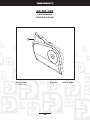
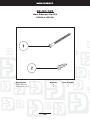
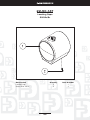
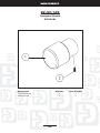
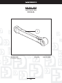
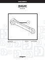
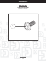
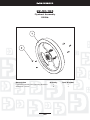
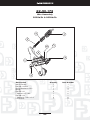
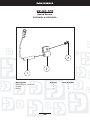
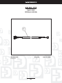
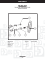
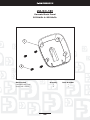
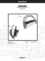
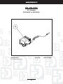
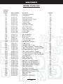
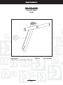
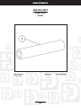
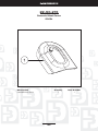
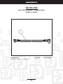
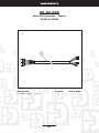
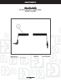
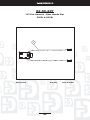
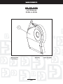
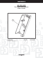
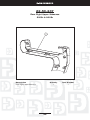
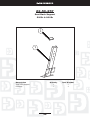
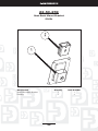
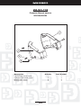
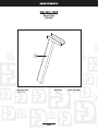
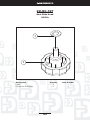
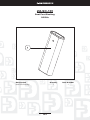
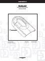
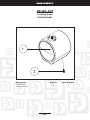
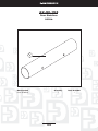
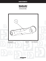
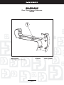
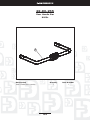
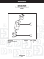
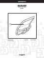
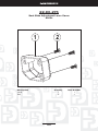
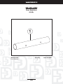
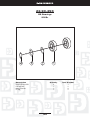
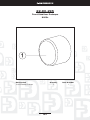
1
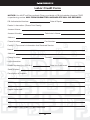
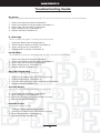
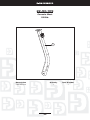
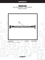
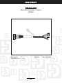
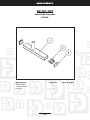
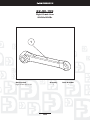
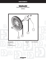
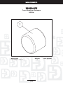
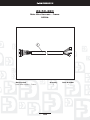
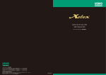
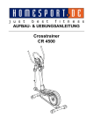
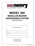
500/900
Service Manual
Product Service Policy
All Diamondback Fitness Dealers are required to agree to the following. This document outlines the
relationship between Diamondback and our authorized dealers in the areas of: a) service after sales; b)
warranty parts support and purchase; and c) labor authorization and support.
1.
It is the responsibility of the Dealer to diagnose/troubleshoot, service, repair or otherwise correct any
problems that may occur with a Diamondback Fitness Product that they sell, regardless of where the
product has been placed.
2. Initial assembly of each Diamondback Fitness unit is the responsibility of the dealer. The Dealer is
responsible for any damage and or costs incurred due to improper assembly, accident, misuse, improper maintenance or failure to follow instructions, and or warnings in the owner’s manual.
3. All warranties are valid from the original date of purchase to the original purchaser only [proof of purchase is required]. In the event that the original date of purchase cannot be verified, the warranty will
be valid from six (6) months after the manufacturing date of the unit.
4. Warranty exclusions for Diamondback products placed under light commercial warranty include:
health clubs, schools or correctional facilities.
5. Diamondback Fitness will credit the Dealer’s account a flat rate of US$85 for each pre-authorized
labor claim. The credit will be issued one time to correct a problem on a unit. Additional labor claims
can be submitted against the unit if another [different] problem occurs during the labor period.
6. If, after working with the Diamondback Fitness Warranty/Technical department a minimum of three
separate occasions, it is determined that we cannot repair a specific problem with a unit, Diamondback will RA the unit and replace, freight prepaid.
7. Defective return units must be boxed in suitable packaging and include all parts and accessories
originally included with the unit. Any parts missing or damage incurred due to improper packaging will
be deducted from the total credit at listed dealer cost.
8. All Diamondback Fitness Dealers will be billed for warranty replacement parts. Dealers receive credit
upon return of the replacement parts to Diamondback. See Warranty Credit Processing policy for
more details.
9. All returned, potentially defective, items are tested on arrival to Diamondback. Dealer will incur a
bench charge for any items that are determined to be in good working order and not defective.
Dealer will incur a bench charge, be re-invoiced for the original cost of the item[s], and will have
item[s] returned freight collect if defective due to abuse; improper installation. See Warranty Credit
Processing policy for more details.
2
Table of Contents
Warranty Information
Product Service Policy ............................................................................................................................. 2
Domestic Warranty Information ............................................................................................................. 4
Ordering Replacement Parts .................................................................................................................. 6
Warranty Order/Credit Processing ........................................................................................................ 7
Labor Credit Policy ................................................................................................................................... 8
Labor Credit Form .................................................................................................................................... 9
Product History Report .......................................................................................................................... 10
Troubleshooting Guide
Electrical System ...................................................................................................................................... 11
Mechanical System ................................................................................................................................ 13
Repair Procedures
Procedure 1 - Checking the wall socket for power ........................................................................... 14
Procedure 2 - Checking the AC adapter for correct output ........................................................... 14
Procedure 3 - Checking the input jack for power ............................................................................. 14
Procedure 4 - Checking wiring harness ............................................................................................. 14
Procedure 5 - Replacing the console ................................................................................................. 14
Procedure 6 - Checking/replacing the RPM sensor ........................................................................ 14
Procedure 7 - Checking the hand pulse wire harness and sensor ................................................ 15
Procedure 8 - Replacing the hand grip pulse sensor ....................................................................... 15
Procedure 9 - Checking /replacing the brake assembly ................................................................. 15
Procedure 10 - Checking /replacing the flywheel assembly ........................................................... 16
Procedure 11 - Checking belt alignment ............................................................................................. 16
Procedure 12 - Checking/replacing the belt tensioner .................................................................... 16
Procedure 13 - Checking/replacing the bottom bracket bearings ................................................ 16
Procedure 14 - Checking/replacing the pedals ................................................................................. 17
Procedure 15 - Checking/replacing the crank arms ......................................................................... 17
Procedure 16 - Removing/Replacing the sidecase .......................................................................... 18
500Ub.Sr Service Menus ............................................................................................................................... 19
900Ub.Sr Service Menus ............................................................................................................................... 21
500Ub Wiring Diagram .................................................................................................................................. 24
900Ub Wiring Diagram .................................................................................................................................. 25
500Sr & 900Sr Wiring Diagram .................................................................................................................... 26
Parts Lists and Exploded Drawings
500Ub Parts List ..................................................................................................................................... 27
500Ub Exploded Drawing .................................................................................................................... 28
500Sr Parts List ....................................................................................................................................... 72
500Sr Exploded Drawing ...................................................................................................................... 74
900Ub Parts List .................................................................................................................................... 114
900Ub Exploded Drawing .................................................................................................................... 116
900Sr Parts List ..................................................................................................................................... 142
900Sr Exploded Drawing .................................................................................................................... 144
3
Domestic Warranty Information
(Applies to all product sold and placed within the continental US, Alaska, Hawaii, and Puerto Rico only)
Effective: May 2008
Diamondback warrants its 500 and 900 model units to be free from defects in material and workmanship under normal use in the home and light instructional environments. Diamondback’s obligation under
this Warranty is limited to repair or replacement of any defective part without charge through an authorized service agent to the original purchaser with the following parameters:
Who is covered:
The Warranty is extended to the individual or legal entity whose name appears on the Warranty registration card filed with Diamondback and may not be transferred to any other individual or legal entity.
To obtain service:
To obtain service you must contact your authorized Diamondback Fitness dealer. Your dealer is also your
authorized service agent. An authorized service agent must diagnose your unit in order to determine
Warranty claims/issues.
Sales where the unit is delivered unassembled (in a carton) to the end user (e.g. mail order or Internet
sales) without a service contract purchased through the dealer voids the Warranty.
Warranty Registration:
Warranty commitments are valid only with a completed Warranty card that is returned within 15 days
from the date of purchase and includes the product serial number. Registration is available at www.diamondbackfitness.com.
Proof of purchase from Diamondback’s authorized dealer will be required if the Warranty card is not registered prior to any consideration of Warranty claim.
What is covered
Home use only
Frame:
Brake:
Parts & Electronics:
Labor:
Lifetime limited Warranty, covers defects in welds, materials, and workmanship.
Lifetime limited Warranty
3 Years
1 Year
Warranty voided if:
The Warranty does not apply to any failure of the product, or any parts of the product, due to: assembly
errors, alterations, modifications, misuse, abuse, accident, improper maintenance, or if the serial number
on the product has been removed, altered or defaced. Assembly errors include but are not limited to:
Damaged wire harness.
Stripped crank arms and/or pedals.
Bolts used in the wrong location.
Parts & Service:
Contact the authorized Diamondback dealer where unit as originally purchased. If you have moved, or
that retailer is unavailable, use our dealer locator at www.diamondbackfitness.com to help find another
authorized dealer.
4
Domestic Warranty Information (Continued)
Diamondback is not responsible for arranging Warranty service and/or honoring extended warranties
provided by dealers.
Exclusions:
Warranty is void if the 500 or 900 model units are placed in a commercial or light commercial environment, such as health club, school, or correctional facility.
Additional Rights:
This Warranty is expressly in lieu of all other warranties, and any implied warranties of merchantability or
fitness for a particular purpose created hereby, are limited to the same duration as the express Warranty
herein. Raleigh America, Inc. shall not be liable for any incidental or consequential damages. Some states
do not allow the exclusion or limitations of implied warranties, incidental or consequential, so the above
limitations and exclusions may not apply to you.
Retailers and wholesale outlets for Diamondback Fitness Inc. products are not authorized to modify this
Warranty in any way.
This Warranty gives the original owner specific legal rights. Other additional rights may vary from state to
state.
Diamondback Fitness
c/o Raleigh America Inc.
6004 S. 190Th St. Suite 101
Kent, WA 98032
5
Ordering Replacement Parts
Please review the following information before placing any order with the Diamondback Warranty Department:
1.
Look up the needed part the Diamondback exercise unit in the appropriate Service Manual. There
are pages that list all sub assembly parts in the Service Manual.
2. The part will be marked with a three (3) digit number. This number corresponds to the last three (3)
numbers in the DB SKU (DB stock keeping unit number). On the Parts List page, all drawing numbers
are listed in ascending numerical order. Next to the drawing number, we list the full DB SKU number,
part description, and page number where you will find the exploded view of the part you have selected.
3. When you turn to the proper page, the Diamondback SKU number will be at the top and the picture
will show all the items that are included with that specific part.
4. If the part is to be ordered as a warranty replacement, be prepared to give the following information
at your time of order placement:
a. The type and model unit.
b. The purchase date.
c. The serial number of the unit.
d. The symptoms the unit is displaying.
5. Diamondback National Warranty can be reached at 800.776.7642 to place parts orders or get troubleshooting advice.
6
Warranty Order/Credit Processing
When a warranty parts order is placed and shipped your account will be invoiced for
the parts that need to be returned. To receive a credit for these defective warranty
parts you will need to return them to Diamondback. To ensure your credit is properly
processed, please follow these steps:
STEP 1: KEEP IT
Keep all warranty order "packing slips" along with all defective parts that have a $ amount in the right column of the form. Destroying of any Warranty part with a cost of more than $0.00 will result in the invoicing of that part to your account.
STEP 2: REVIEW IT
If you have any questions or aren't sure of which parts need to be returned, contact the Diamondback
Warranty Department to review the packing slip and items.
STEP 3: SENT IT
If any of the item(s) on the packing slip have a cost greater than $0.00 a DHL EZ Return tag will be included. Send the return item(s) along with the "packing slip" via DHL using our DHL EZ Return tag WITHIN 45 DAYS TO EXPEDITE CREDIT
WHAT IF?
Q: What if all the items on the packing slip show a cost of $0.00?
A: If all the items on the form have a cost of $0.00 please immediately and properly destroy the defective
parts. No credit to you account is needed since you will be invoiced for $0.00.
Q: What if there are items that you need to return but didn't receive a DHL EZ Return tag?
A: Call Diamondback's National Customer Service/Warranty at (800) 776-7642 and we will mail a tag to
you.
If you have any other questions, don't hesitate to call the Diamondback warranty department - (800)
776-7642.
Effective Date: August 2008
7
Labor Credit Policy
In the event a Diamondback Fitness unit is delivered with a factory defect or if a malfunction occurs within the prescribed warranty period, an authorized Diamondback Fitness dealer can file for a labor stipend.
To ensure prompt credit for your labor, follow the guidelines listed below:
1. Verify the purchase date of the unit. Proof of Purchase may be required. In the event that the original
date of purchase cannot be verified, the warranty will be valid from six (6) months after the manufacturing date of the unit.
2. Verify the warranty of the unit. The Warranty for a Diamondback Fitness unit can be found in the back
of the original owner's manual.
3. Call Diamondback's National Warranty / Customer Service prior to attempting any repairs to receive
a work authorization number. Please be prepared to give the following information:
a. Your Diamondback account number and location
b. Model of unit
c. Specific problem the unit is experiencing
d. Date of purchase
e. Serial number of unit
4. Your Diamondback Tech Rep will issue a work authorization number and/or enter an order for the
necessary parts.
5. Once the servicing Diamondback Fitness dealer receives the parts, he should make the necessary
repairs and complete the labor credit form.
6. NOTE: completed forms help expedited the claim reimbursement. Once the labor credit form has
been filled out, return it to the address listed below or fax it to Diamondback Warranty at (800) 3959548.
7. If the labor claim meets all the above listed criteria, Diamondback Fitness will credit the dealer's account a flat rate [based on 2008 leveling program] for each pre-authorized claim. The credit will be
issued on time to correct a problem on a unit. Additional labor claims can be summated against the
unit if another problem occurs during the labor period.
8. ALL returned, potentially defective, items will be tested on arrival. Dealer may incur a $30.00 bench
charge for any items that are determined to be in good working order and not defective. Dealer may
incur a $30.00 bench charge, be re-invoiced for the original cost of the item(s) returned freight collect if defective due to abuse; improper installation.
If you have any questions, contact National Warranty/Customer Service Department @ (800) 776-7642.
Effective Date: August 2008
8
Labor Credit Form
NOTICE: You MUST call Diamondback Fitness and obtain a DB Authorization Number PRIOR
to performing service. ANY FORM SUBMITTED INCOMPLETE WILL BE REFUSED.
DB Authorization Number:
Date of Repair:
Dealer’s Information: (Please Print Clearly)
Account Name:
Account Number:
Technician’s Name:
Address:
Phone Number:
Fax Number:
Facility’s / Consumer’s Information that Received Service:
Name:
Address:
Phone Number:
Contact:
Unit Information:
Date Unit Purchased:
Model Repaired (i.e.: 500Ub ):
Serial Number:
Description of Problem:
Repair Performed:
FAX COMPLETED FORM TO 1-800-395-9548
9
Product History Report
Dealer:
Service Date
Account Number:
1
Technician:
2
Phone:
3
Fax:
4
Model:
5
Sales Order
RA Number
Serial Number:
Consumer's Name:
Sales Order # for any parts received for repair.
Date of Purchase:
RA Number for labor authorization for repair.
Consumer Phone/Fax/Contact:
Consumer's Address:
-----Service Information----All fields must be filled out completely including the sales order number which replacements parts (if any) were ordered under.
Original Complaint
1st Service (parts replaced)
2nd Service (parts replaced)
3rd Service (parts replaced)
Fill out form completely and fax to the Diamondback Fitness Warranty Department at 1.800.395.9548. Any potential unit
return must meet criteria set forth in the Product Service Policy, line item 7, a copy of which is attached with this sheet.
10
Troubleshooting Guide
No power
There is no apparent power to the console. LEDs and LCDs are not lit up and keys are not functioning.
1.
2.
3.
4.
5.
Check wall socket for power (Procedure 1).
Check AC adapter for correct output (Procedure 2).
Check input jack for power (Procedure 3).
Check wiring harness (Procedure 4).
Replace console (Procedure 5) .
E-1 Message
There is an error message E-1 showing on the data matrix.
1.
2.
3.
4.
Unplug the power cord and plug back in.
Check motor on brake assembly (Procedure 9).
Check wiring harness (Procedure 4).
Replace brake assembly (Procedure 9).
Partial LED's
The console has power but some of the console lights are dim or out completely.
1.
2.
3.
4.
5.
Check wall socket for power (Procedure 1).
Check AC adapter for correct output (Procedure 2).
Check input jack for power (Procedure 3).
Check wiring harness (Procedure 4).
Replace console (Procedure 5).
Keys Not Responding
No changes when keys are depressed.
1.
2.
3.
4.
Check user’s programming (See owner’s manual).
Check wiring harness (Procedure 4).
Run console test program (See test program instructions).
Replace console (Procedure 5).
Console Resets
The console starts normally then resets during workout.
1.
2.
3.
4.
Check input jack for power (Procedure 3).
Check wiring harness (Procedure 4).
Check user’s programming (See owner’s manual).
Replace console (Procedure 5).
Console Frozen
No change in display or data.
1.
2.
3.
4.
Unplug the power cord and plug back in.
Check user’s programming (See owner’s manual).
Check wiring harness (Procedure 4).
Replace console (Procedure 5).
11
Troubleshooting Guide (Continued)
No RPM
RPM, Calories, Distance show "0" on Data window.
1.
2.
3.
4.
Check other console function (time, pulse, level).
Check wiring harness (Procedure 4).
Check RPM sensor (Procedure 6).
Replace console (Procedure 5).
Max Resistance
Get max resistance at Level 1 or it is very hard to pedal right after power on.
1.
2.
3.
4.
5.
Check user’s programming (See owner’s manual).
Check to see if all moving components spin freely.
Check wiring harness (Procedure 4).
Check belt alignment (Procedure 10).
Check brake assembly (Procedure 9).
No Resistance Change
Unit turns on but the resistance won't change when requested at the console.
1.
2.
3.
4.
Check user’s programming (See owner’s manual).
Check wiring harness (Procedure 4).
Check brake assembly (Procedure 9).
Replace console (Procedure 5).
Hand Grip Pulse Heart Rate Problem
Erratic heart rate reading; too low, too high, or not working at all.
1.
2.
3.
4.
5.
Moisten hands lightly and retry.
Check results with another user.
Check hand pulse wire harness (Procedure 7).
Check hand grip pulse sensors (Procedure 8).
Replace the console (Procedure 5).
Chest Strap Heart Rate Problem
Erratic heart rate reading; too low, too high, or not working at all.
1. Check the chest strap belt transmitter.
2. Check for interference from outside source.
3. Replace console (Procedure 5).
Programming Problem
Not starting correctly, not accepting program time, not taking user info, etc.
1. Check user’s programming (See owner’s manual).
2. Run console test program (See test program instructions).
3. Replace console (Procedure 5).
12
Troubleshooting Guide (Continued)
Mechanical Noise
Grinding, Ticking & Clicking. Thumping, Squeaking & Squealing. Twanging/Spring noise.
1.
2.
3.
4.
5.
6.
7.
Check bottom bracket bearings (Procedure 12).
Check pedals (Procedure 13).
Check crank arms (Procedure 14).
Check to see if all moving components spin freely.
Check belt alignment (Procedure 10).
Check belt tensioner (Procedure 11).
Check brake assembly (Procedure 9).
Pedal Slipping
Sudden resistance change in pedals under higher resistance and/or RPM.
1. Check belt alignment (Procedure 10).
2. Check belt tensioners (Procedure 11).
3. Clean Pulley surface and replace belt .
13
Repair Procedures
Procedure 1
Checking the wall socket for power
1.
2.
3.
4.
Check whether there is a wall switch controlling this wall socket.
Set the voltmeter to the appropriate setting for your country. (U.S. = AC/200 volt setting)
Place the test leads into the hot and neutral receptacles on the outlet.
Your meter should display the appropriate output for your region. (U.S. = 110-120 volts)
Procedure 2
Checking the AC adapter for correct output
1. Plug the AC adapter into functioning outlet.
2. Check the output with your voltmeter by setting it to the DC/20 volt setting.
3. Place the test lead inside the male plug end of the adapter and the second lead on the outer metal
surface of the plug.
4. The voltmeter should read between 10 and 20 DC volts. 1
Procedure 3
Checking the input jack for power
1.
2.
3.
4.
Remove the left sidecases from the unit (Procedure 15).
Leave the AC adaptor plugged in to wall & input jack.
Set the voltmeter to the DCV/20 Volt setting.
Locate the two wires from the main wire harness which connect with the back of the input jack.
Touch the two test leads to these connection points, being sure to make contact with metal.
5. The voltmeter should read between 10 and 20 DC Volts.
Procedure 4
Checking wiring harness
1.
2.
3.
4.
5.
6.
Remove the sidecases from the unit (Procedure 15).
Inspect all the connecting points and that the pins are correctly inserted into the plugs.
Visually inspect each wiring harness for cuts, burns or melted spots.
Check that the harness that runs to the console is not pinched.
Note: During installation of the console mast the wiring harness may get pinched or cut.
With the unit plugged in, check the voltage at the harness/console connector, P1 (referring to wiring
diagram). Set the voltmeter to a 20VDC setting.
Procedure 5
Replacing the console
1.
2.
3.
4.
Remove the 4 Phillips screws from the console back panel on the back of the console.
Unplug the connectors from the back of the console.
Remove the 4 Phillips screws from the back of the console
Reverse the process for installation.
Procedure 6
Checking/replacing the RPM sensor
1.
Checking the RPM sensor
a. Remove the sidecases from the unit (Procedure 15).
b. Verify that the drive pulley magnet is still in its slot on the interior face of the pulley.
14
Repair Procedures (Continued)
c.
d.
e.
f.
g.
h.
Make sure that the RPM sensor is sufficiently close to the pulley (approx. 6/16 inch).
Verify that the RPM sensor is plugged in to the wire harness by following the wire.
Set the multimeter to read resistance (0hms).
Detach sensor wiring from main wire harness, and place test leads inside sensor connector.
With the magnet rotated away from the sensor, the multimeter should read infinite resistance.
With the magnet rotated adjacent to the sensor, the multimeter should read close to 0 Ohms.
2. Replacing the RPM sensor
a. Remove the original RPM sensor by unscrewing and unplugging it from the wire harness.
b. Install the new RPM sensor by screwing in place and plugging in it to the wire harness.
c. Be sure to place the sensor close to the pulley magnet while making sure that no physical contact occurs (approx. 6/16 inch).
Procedure 7
Checking the hand pulse wire harness and sensor
1. Remove the 4 Phillips screws from the back panel of the console.
2. Check that the hand pulse wire connector is plugged into the wires coming out of the console securely.
3. Use a multimeter to check continuity from the connector plug to stainless steel hand pulse sensor.
4. If there is no continuity, proceed to remove the grip sensor steel plates as described in Procedure 8
to check connection of wire harness to the sensor.
Procedure 8
Replacing the hand grip pulse sensor
1.
2.
3.
4.
Remove the Phillips screw on the bottom of the handlebar.
Unplug the two connectors on the back of the hand grip pulse sensor.
Remove the hand grip pulse sensor.
Reverse the process for installation.
Note: Be careful while putting the screw back on not to pinch the wire harness
Procedure 9
Checking /replacing the brake assembly
1.
Checking the Motor Assembly
a. Remove the sidecases from the unit (Procedure 15).
b. Verify that the motor wire harness is plugged in to the main wire harness.
c. Check the solder connections on motor and position sensors.
d. With unit plugged in, raise the resistance up to maximum and observe whether the motor rotates.
If possible, plug in another similar console and repeat previous procedure.
e. With unit plugged in, raise the resistance up to maximum and observe whether the arch of magnets rub against the flywheel. This will create noise and/or stop the flywheel from spinning. Adjust if necessary, see replacement procedure.
2. Replacing the brake assembly
a. Remove the sidecases from the unit (Procedure 15).
b. Unplug the motor from the main wire harness.
c. Remove the two bolts that attach the brake assembly to the frame
d. Reverse the process for installation.
Note: Increase the resistance to level 16 and make sure the arch of magnets is 2mm away from
the flywheel. Loosen the mounting bolt right next to the motor and using the adjustment nuts on
15
Repair Procedures (Continued)
the side of the brake adjust this distance if necessary.
Procedure 10
Checking /replacing the flywheel assembly
1.
Checking the flywheel assembly
a. Remove the sidecases from the unit (Procedure 15).
b. Derail the drive belt from off the drive pulley.
c. Spin the flywheel by hand and inspect for noise and/or motion impediment.
d. Verify that flywheel is securely mounted in place.
2. Replacing the flywheel assembly
a. Remove the sidecases from the unit (Procedure 15).
b. Derail the drive belt from off drive pulley.
c. Loosen the flywheel mounting bolts.
d. Remove the flywheel.
e. Reverse procedure with new brake to install.
Procedure 11
Checking belt alignment
1.
Inspecting for belt slip
a. Remove the sidecases from the unit (Procedure 15).
b. Check the belt and belt tensioners for proper tension and adjust if necessary.
c. Pedal the unit above 60 RPM and adjust the resistance up to its highest setting.
d. Keep pedaling and have an assistant visually check all the belts and pulleys for slipping.
2. Adjusting for proper tension
a. The belt tensioner should be centered on the belt while pedaling and holding it taut.
b. Raising the tension by tighten the bolt at the end the tensioner spring pulling the tensioner. Tighten the bolt one turn at a time until the proper tension is reached.
Procedure 12
Checking/replacing the belt tensioner
1.
Checking the belt tensioner
a. Remove only the right side case from the unit (Procedure 15).
b. By hand, turn the pedal backward and observe the belt position on the belt tensioner.
c. Switch directions to turn pedal forward and observe whether belt changes direction on the tensioner.
2. Replacing the belt tensioner
a. Remove the sidecase from the unit (Procedure 15).
b. Derail the poly-v Drive Belt.
c. Remove the four bolts that hold the belt tensioner assembly in place.
d. Add grease on the surface of the replacement tensioner which is contacting the frame of the unit.
e. Reverse the process for installation.
Procedure 13
Checking/replacing the bottom bracket bearings
1.
Basic test for bad crank bearings
a. Check for bearing play by pulling the crank arms laterally. Replace if there is any lateral move-
16
Repair Procedures (Continued)
ment.
b. Sit on the bike and pedal above 80RPM. Stop pedaling and allow the bike to freewheel. If the
noise continues, the damage is most likely to the flywheel. If the noise stops, the damage is most
likely to the crank bearings or idler bearings.
c. Slide off the drive belt from the drive pulley.
d. Spin crank by hand to see if there is noise.
e. Spin belt tensioner to see if there is noise.
2. Replacing the bottom bracket bearings
a. Remove the pedals and crank arms from the unit (Procedures 13 & 14)
b. Remove the sidecases from the unit (Procedure 15).
c. Derail drive belt from pulley.
d. Remove the C-ring from the left side of the crank axle.
e. Slide the Drive Pulley with crank axle off the unit. You may have to use a hammer on the left side
to tap on the axle
f. Punch out the defective ball bearings using a shaft and a hammer.
g. Insert the new bearing into the frame of the unit.
h. Install the Drive Pulley and Axle onto the frame from the right side.
i. Keeping pressure on both bearing surfaces, press the bearings so they fit securely within the
frame.
j. Secure the C-Ring clip into place just beyond this second bearing.
k. Install the sidecases.
l. Install the crank arms, making sure to tighten the crank bolts or nuts to at least 450 kg-cm of
torque.
Procedure 14
Checking/replacing the pedals
1.
Pedal inspection
a. Check that the pedals are firmly tightened to the crank arms.
b. Spin the pedals with your hand. The bearings should feel smooth.
c. While grabbing the outside edge of the pedal, move it up and down to check for play. They
should have no play
2. Pedal replacement
a. Remove the pedals with a 15mm open end or adjustable wrench (Note: The left pedal is reverse
thread).
b. Reverse the process for installation. Retighten pedals after each 8 hours of use.
Procedure 15
Checking/replacing the crank arms
1.
Crank arm inspection
a. Check that the crank spindle bolts or nuts are tight.
b. Check for play by pulling the crank arms laterally. Be sure it isn't a bad crank bearing assembly
causing any movement.
2. Crank arm replacement
a. Remove the pedals with a 15mm open end or adjustable wrench
b. Remove the spindle bolts or nut from the crank arms.
c. Using a standard bicycle crank puller, remove the crank arms.
d. Reverse the process for installation.
17
Repair Procedures (Continued)
Procedure 16
Removing/Replacing the sidecase
1. Remove the bolts from the crank arms.
2. Use a standard bicycle crank puller to remove the crank arms.
3. Remove the Phillips head screws from the sidecases.
4. Reverse the process for installation.
18
500Ub.Sr Service Menus
There are two service menus on this console:
A. The Console Diagnostics menu which checks the functionality of the console. It also displays the
software version and the accumulated run time. In addition it has a Model Switching feature that
changes the active model the console is operating on from 2 options: Cycles and ellipticals
B. The English and Metric switching menu which changes the display units from pounds, miles, and
miles/hour to kg, km and km/hour.
A. Console Diagnostics
1. Press and hold the Enter Key for 2 seconds
2. Press Enter Key to toggle through the Service Mode states. To terminate the Service mode without
going through all the steps, press & hold “Stop” key for 2 seconds to reset the console.
3. Software Version – The Dot Matrix display will display the software as “SW” “1.0”
a. First display “SW”
d. Then display “1.0” and it will Wait for the Enter key to be pressed
4. Reset to Factory Defaults – When the Enter key is pressed after the software version is displayed, it
will allow for the console to be reset to Manufacture defaults.
a. The Dot Matrix will flash “RS”, and then display an “N”. The Up and Down keys can be use to
toggle between an “N” and a “Y”.
b. If the Enter key is pressed while the “N” is on the display nothing will change.
c. If the Enter key is pressed while the “Y” is on the display the model setting will change to UR, Age
will rest to 35years, the Weight will reset to 155lbs, the Custom Trainer profile will reset to its default profile (see section 11.3.4 for profile)
5. Model Setting: When the Enter key is pressed after the Reset to Facture selection is done the Dot
Matrix will display configuration of the console as “UR” or “EF”.
a. Up/Down keys can be pressed at this point to switch the mode. The mode determines which
Watt table and Calorie calculation is used.
b. Wait for the Enter key to be pressed to move to the next step in Service Mode.
6. Memory Test – When the Enter key is pressed after the Model Setting is done, it will test the memory,
if OK it will display “OK” in Dot Matrix or “NG” if it is bad.
7. Accumulated time – When the Enter key is pressed after the memory test is completed, it will display
the accumulated time in the time display.
8. Perform Display test – When the Enter key is pressed after the accumulated time is displayed, enter
the display test.
a. All of the LEDs, and in the LCD will light up at once.
b. All LEDs and displays will turn off
19
500Ub.Sr Service Menus (Continued)
c. The Dot Matrix will light up row-by-row and column-by-column. At the same time the program
LED Indicators will light up one by one.
d. Every segment in of the digits in the data display windows will light up segment by segment.
e. All messages will light up.
f. This process will repeat itself until the enter key is pressed
9. Perform Key test – When the Enter key is pressed after the Display Test, enter the Key test. When
Display Test is completed, all program LED Indicators will light up, and the LDC will turn off
a. Press Program key and its associated LEDs will turn off and the default workout profile will be
displayed in the Dot matrix.
b. Press function key, the Pulse display will display an associated number to indicate each key, see
table below.
Up
Down
Enter
Start
Stop
Fan
1
2
3
4
5
6
c. Press ENTER key during keypad test, 1st time “Enter” key is pressed, the pulse display will show
the number 3 to indicate this key test. 2nd time pressed, it will go into the next test state.
10. Perform RPM and Pulse test - When the Enter key is pressed after the Key test, enter the RPM & HR
test.
a. The massages RPM and Pulse will light up
b. If there is an RPM signal detected, the RPMs will be displayed in the RPM display. Otherwise,
“---” will be displayed.
c. If a HR device is engaged it will display the current HR in the Pulse display. Otherwise, “---” will be
displayed.
11. Perform Brake Motor Test - When the Enter key is pressed after the RPM and Pulse test, enter the
Brake test. It will increase the resistance from level 1 to level 16 and back down to level 1. The brake
motor feedback voltages will be:
Level
1
2
3
4
5
Voltage 0.05 0.39 0.52 0.63 0.69
Level
9
Voltage 0.89
6
7
8
0.76
0.81
0.85
10
11
12
13
14
15
16
0.91
0.94
0.97
1.0
1.02
1.04
1.06
12. End Self Diagnostics - When the Enter key is pressed after the Brake test, reset to Idle mode
B. Metric/English Units Setting
Factory Default display is English system: Weight = lbs, speed = mile/hr, distance = miles
1. Switch English to Metric System: Press and hold the START & ENTER keys at the same in idle mode.
2. The dot matrix window will display “EN” message when it is in English units or “ME” when it is in Metric
units.
3. Press “UP or DOWN” key to switch ENGLISH units to METRIC units or Metric to English.
4. Press “ENTER” key to accept the new setting and return to idle mode.
Note: A Reset to Factory Defaults (from Service Mode) will reset the console to English units.
The Service Menus allow testing of proper console function as well as adjustment of basic features of
the console.
20
900Ub.Sr Service Menus
Basic Operation
Service Menus are accessed from Idle Mode by holding down the “Enter” key for 2 seconds. The Up
and Down keys can be pressed to scroll through the following 5 menu choices:
A.
B.
C.
D.
E.
Self Tests
Units Setup
Model Setting
Sound Setup
Reset to Factory Defaults
To activate a menu function, scroll to the function, then press Enter key. If there is no key pressed within
5 seconds, the console will automatically return to Idle Mode.
A. Self Tests
1. Scroll to the Self Tests menu choice in the Service menu choices and press the Enter key.
2. Once the self tests are entered the Star/Stop key can be pressed and help for 2 seconds to return to
Idle Mode.
3. Software Version Test: the console will show the software version on the alphanumeric display with a
message that will read “SOFTWARE V1.0”; the number will change according to the software version.
Press the Enter key
4. Total Console Hours Test: The total use hours of the console will be shown on the alphanumeric display with the message “TOTAL USE = XXXXHR”. Press the Enter key
5. Memory Test: The memory of the console will be tested and the message display will display “RAM
OK” to indicate that there are no problems with the memory, if it finds a problem it will display “RAM
NOT OK”. Press the Enter key
6. Display Test: The Alphanumeric window will show the message “DISPLAY TEST”. Then it will start its
activity as below.
a. All the LEDs turn on at once including the segments and messages in the Main Display and Alphanumeric Display.
b. All LEDs will turn off. In the Main LCD everything will turn off, only the Messages will stay on with
the message “DISPLAY TEST”.
c. The message display will turn off the message “DISPLAY TEST” and will light up one segment of
every character at the time.
d. Every program will be tested and the program name will be display in the message display and
the profile will be displayed in the dot matrix.
e. This process will repeat itself until the enter key is pressed
7. Key Test: The message display will show the message “KEY TEST”.
a. Press any key to test that it is working. When a key is pressed, the message display will show the
name of program under that key or the name of that key. The associated LED(s) with that key will
light up. The display will show the following names for the keys:
Manual Program Key: MANUAL
Random Program Key: RANDOM
Interval Program Key: INTERVAL TRAINER
Hill Climb Program Key: HILL CLIMB
Fitness Test Program Key: FITNESS TEST
Strength Program Key: STRENGTH
Custom Trainer Program Key: CUSTOM TRAINER
Target HR Program Key: TARGET HR
HR Interval Program Key: HR INTERVALS
21
900Ub.Sr Service Menus (Continued)
Data display Key: SELECT
Start/Stop Key: START/STOP
Enter Key: ENTER
Display Key: DISPLAY
Level Up Key: LEVEL UP
Level Down Key: LEVEL DOWN
Fan Key: FAN
b. The first time the Enter key is pressed, it will show the key name on the display. The second time
Enter is pressed the console will move to the Heart Rate/RPM Test.
8. Heart Rate/RPM Test: The alphanumeric display will show the message “RPM/HR TEST”. The display will then show “RPM = XXX HR = XXX” if there is a RPM or HR device engaged. Otherwise, it will
display “RPM = - - - HR = - - -”. When Enter is pressed, the console will move to the Brake Test.
9. Brake Test: The display will show the following message “BRAKE TEST” then “INTENSITY = 1”.
a. The test will begin with the brake motor set to Level 1.
b. Press the Up key to increase the resistance to the next level or Down to decrease by one level.
c. For each change in the brake motor setting, the display will show the next intensity level. The
brake motor feedback voltage will be:
Level
1
2
3
4
5
Voltage 0.05 0.39 0.52 0.63 0.69
Level
9
Voltage 0.89
6
7
8
0.76
0.81
0.85
10
11
12
13
14
15
16
0.91
0.94
0.97
1.0
1.02
1.04
1.06
d. When the Enter key is pressed the console will return to Idle Mode.
B. Units Setup
1. When Enter is pressed on this menu choice, the Alphanumeric will display “ENGLISH” or “METRIC”
depending on the setting of the console. The Up/Down keys can then be used to scroll between the
two.
2. If Enter is pressed while “METRIC” is shown on the display, the console will be set to use metric units
(kg, km) for all distance, speed, and weight displays.
3. If Enter is pressed while “ENGLISH” is shown on the display, the console will be set to use English
units (lb, miles) for all distance, speed, and weight displays.
4. Once Enter is pressed and the console units are set, the console will return to the Idle Mode.
5. A Reset to Factory Defaults will always return the console to using English units.
C. Model Setting
1. When Enter is pressed on this menu choice, the console will display the current model setting of the
console:
“ER” = Rear drive elliptical
“UR” = Upright/recumbent
More model choices may be added to the software in the future to support more products.
2. The Up/Down keys can then be used to scroll between the models.
3. When Enter is pressed again, the model will be selected and the model selected.
Note: A Reset to Factory Defaults will all rerun the console to UR model setting
D. Sound Setup
1. When Enter is pressed on this menu choice, the message display will display “SOUND ON” or
“SOUND OFF”, depending on the setting
22
900Ub.Sr Service Menus (Continued)
2. The Up/Down keys can then be used to scroll between the two
3. If Enter is pressed while “SOUND ON” is shown on the display, the console beeper will be active.
4. If Enter is pressed while “SOUND OFF” is shown on the display, the console beeper will be disabled.
No sound at all will come from the console in any mode or when any key is pressed.
5. Once Enter is pressed and the beeper will start or stop beeping depending on what was selected
and the console will return to the Idle Mode.
Note: A Reset to Factory Defaults will always return the console to “sound on”.
E.
1.
2.
3.
Reset to Factory Defaults
When Enter is pressed on this menu choice, the message display will show “FACTORY RST = NO”
Use the Up/Down keys to scroll between “YES” and “NO”.
If Enter is pressed on the “YES” choice, the console will reset all memory locations to factory defaults.
The model setting will change to UR, Age will rest to 35years, the Weight will reset to 155lbs, the Custom Trainer profile will reset to its default profile
4. If “NO” is chosen, console will return to Idle Mode without resetting anything.
Note: Performing a Reset to Factory Defaults will NOT reset the Total Console Hours value inside the
Service Menu.
23
500Ub Wiring Diagram
24
900Ub Wiring Diagram
25
500Sr & 900Sr Wiring Diagram
26
500Ub Parts List
Exploded
Drawing
Number
101
103
105
107
109
111
113
115
117
119
121
123
125
127
129
131
133
135
137
139
141
143
145
147
149
151
153
157
159
161
163
165
167
169
171
173
175
177
179
181
281
354
900
183
DB Part Number
Description
22-50-101
22-50-103
22-50-105
22-50-107
22-50-109
22-50-111
22-50-113
22-50-115
22-50-117
22-50-119
22-50-121
22-50-123
22-50-125
22-50-127
22-50-129
22-50-131
22-50-133
22-50-135
22-50-137
22-50-139
22-50-141
22-50-143
22-50-145
22-50-147
22-50-149
22-50-151
22-50-153
22-50-157
22-50-159
22-50-161
22-50-163
22-50-165
22-50-167
22-50-169
22-50-171
22-50-173
22-50-175
22-90-177
22-50-179
22-50-181
22-50-281
22-09-354
22-50-900
22-50-183
Console Assembly
Handle Bar Assembly
HP Sensors
HR Wire Harness - Handle Bar
Console Mast
Water Bottle Set
Console Mount Covers
Handle Bar Covers
Console Mount
Main Wire Harness - Console Mast
Main Wire Harness - Frame
Seat Post
Seat Slide Adjuster
Seat Slide Knob
Saddle
Seat Post Bushing
Seat Post Cover
Seat Pin Assembly
Console Mast Cover
Left Sidecase
Right Sidecase
Crank Insert
Main Sidecase Bolt Kit
Leveling Caps
Transport Wheels
Front Stabilizer
Rear Stabilizer
Left Crank Arm
Right Crank Arm
Crank Arm Hex Bolt
Flywheel
Brake Assembly
Drive Pulley
Drive Belt
BB Bearing Kit
Idler Assembly
Speed Sensor
Input Jack
Handle Bar Adjustment Knob & Hardware
Console Back Panel
Pedals & Straps
AC Adapter
Owner's Manual
Assembly Hardware Kit
Page No.
27
30
31
32
33
34
35
36
37
38
39
40
41
42
43
44
45
46
47
48
49
50
51
52
53
54
55
56
57
58
59
60
61
62
63
64
65
66
67
68
69
70
71
-
500Ub Explo
oded Drawing
22-50-101
Console Assembly
500Ub/500Sr
Description
Console assembly
Screw M5 x 10mm
Quantity
1
4
30
Item Number
1
2
22-50-103
Handle Bar Assembly
500Ub
Description
Handle Bar Assembly
Quantity
1
31
Item Number
1
22-50-105
HP Sensors
500Ub/Sr & 900Ub
Description
HP Sensor
Screw M3 x 20mm
Quantity
2
2
32
Item Number
1
2
22-50-107
HR Wire Harness - Handle Bar
500Ub
Description
HR Wire Harness Handle Bar
Quantity
1
33
Item Number
1
22-50-109
Console Mast
500Ub
Description
Console Mast
Quantity
1
34
Item Number
1
22-50-111
Water Bottle Set
500Ub/Sr & 900Ub
Description
Water bottle
Cage
Screws M4 x 14mm
Quantity
1
1
2
35
Item Number
1
2
3
22-50-113
Console Mount Covers
500Ub/Sr
Description
Right Console Mount Cover
Left Console Mount Cover
Screws M3 x 14mm
Screws M5 x 14mm
Quantity
1
1
3
2
36
Item Number
1
2
3
4
22-50-115
Handle Bar Covers
500Ub
Description
Top Handle Bar Cover
Bottom Handle Bar Cover
Screws M5 x 25mm
Screws M3 x 14mm
Quantity
1
1
4
2
37
Item Number
22-50-117
Console Mount Bracket
500Ub/Sr & 900Ub/Sr
Description
Console Mount Bracket
Screws M5 x 10mm
Quantity
1
4
38
Item Number
1
2
22-50-119
Main Wire Harness - Console Mast
500Ub & 900Ub
Description
Main Wire Harness - Console Mast
Quantity
1
39
Item Number
1
22-50-121
Main Wire Harness - Frame
500Ub
Description
Main Wire Harness - Frame
Quantity
1
40
Item Number
1
22-50-123
Seat Post
500Ub
Description
Quantity
41
Item Number
22-50-125
Seat Slide Adjuster
500Ub
Description
Seat Support
Locking Bracket
End Cap
Quantity
1
1
2
42
Item Number
1
2
3
22-50-127
Seat Slide Knob
500Ub
Description
Knob
Flat Washer 14.3 x 25 x 2T
Quantity
1
1
43
Item Number
1
2
22-50-129
Saddle
500Ub
Description
Saddle
Quantity
1
44
Item Number
1
22-50-131
Seat Post bushing
500Ub
Description
Seat Post Bushing
Quantity
1
45
Item Number
1
22-50-133
Seat Post Cover
500Ub
Description
Seat Post Cover
Quantity
1
46
Item Number
1
22-50-135
Seat Pin Assembly
500Ub
Description
Seat Pin Assembly
Quantity
1
47
Item Number
1
22-50-137
Console Mast Cover
500Ub
Description
Console Mast Cover
Quantity
1
48
Item Number
1
22-50-139
Left Sidecase
500Ub & 900Ub
Description
Left Sidecase
Quantity
1
49
Item Number
1
22-50-141
Right Sidecase
500Ub & 900Ub
Description
Right Sidecase
Quantity
1
50
Item Number
1
22-50-143
Crank Arm Insert
500Ub/Sr & 900Ub/Sr
Description
Crank Arm Insert
Quantity
1
51
Item Number
1
22-50-145
Main Sidecase Bolt Kit
500Ub & 900Ub
Description
Screw M4 x 50
Screw 3/16" x 3/4"
Quantity
5
6
52
Item Number
1
2
22-50-147
Leveling Caps
500Ub/Sr
Description
Leveling Cap
Screw 3/16" x 3/4"
Quantity
2
2
53
Item Number
1
2
22-50-149
Transport Wheels
500Ub/Sr
Description
Transport Wheel
Screw M3 x 8
Quantity
2
2
54
Item Number
1
2
22-50-151
Front Stabilizer
500Ub
Description
Front Stabilizer
Quantity
1
55
Item Number
1
22-50-153
Rear Stabilizer
500Ub
Description
Rear Stabilier
Quantity
1
56
Item Number
1
22-50-157
Left Crank Arm
500Ub/Sr
Description
Left Crank Arm 9/16"
Quantity
1
57
Item Number
1
22-50-159
Right Crank Arm
500Ub/Sr
Description
Right Crank Arm 9/16"
Quantity
1
58
Item Number
1
22-50-161
Crank Arm Hex Bolt
500Ub & 900Ub
Description
Hex Bolt M8xP1.0x20L
Quantity
2
59
Item Number
1
22-50-163
Flywheel Assembly
500Ub
Description
Flywheel Assembly with mounting brackets
Screw M5 x 10mm
60
Quantity
1
6
Item Number
1
2
22-50-165
Brake Assembly
500Ub & 900Ub
Description
Bolt M6 x 16mm
Lock Washer
Flat Washer 6 x 13 x 1
Brake Assembly
Flat Washer 8 x 19 x 2
Spacer
Adjustment Bolt M6 x 63mm
Bolt M8 x 22mm
Hex Nuts M6
Quantity
2
2
2
1
1
1
1
1
2
61
Item Number
1
2
3
4
5
6
7
8
9
22-50-167
Drive Pulley (Assemble)
500Ub
Description
Permanent Magnet
Drive Pulley
Axle
Bolt M8 x 12mm
Quantity
1
1
1
3
62
Item Number
1
2
3
4
22-50-169
Drive Belt
500Ub & 900Ub
Description
Drive Belt J6 1059
Quantity
1
63
Item Number
1
22-50-171
BB Bearing Kit
500Ub
Description
C Clip 17 x 65
Wavy Washer
Flat Washer
C Clip 40 x 65
Bearings 6203 (RS)
Quantity
1
1
1
2
2
64
Item Number
1
2
3
4
5
22-50-173
Idler Assembly
500Ub/Sr & 900Ub/Sr
Description
Idler Assembly
Bolt M6 x 40mm
Spring Bracket 14 x 30
Spring
Bolt M5 x 10
T Spacer 9 x 5 x 6.5
Bolt M8 x 16
T Spacer 13.7 x 8.2 x 5.5
Flat Washer
Quantity
1
1
1
1
3
1
1
3
1
65
Item Number
1
2
3
4
5
6
7
8
9
22-50-175
Speed Sensor
500Ub/Sr & 900Ub/Sr
Description
Speed Sensor with Wires
Bracket
Screw
Quantity
1
1
1
66
Item Number
1
2
3
22-90-177
Input Jack
500Ub & 900Ub
Description
Input jack
Quantity
1
67
Item Number
1
22-50-179
Hanble Bar Adjustment Knob
500Ub & 900Ub
Description
Knob
Bolt M7 x 30mm
Sleeve
Lock Washer
Flat Washer
Bracket
Quantity
1
1
1
2
2
1
68
Item Number
1
2
3
4
5
6
22-50-181
Console Back Panel
500Ub/Sr & 900Ub/Sr
Description
Console Back Panel
Screw M5 x 10mm
Quantity
1
4
69
Item Number
1
2
22-50-281
Pedals & Straps (PR)
500Ub/Sr
Description
Right Pedal & Strap
Left Pedal & Strap
Quantity
1
1
70
Item Number
1
2
22-09-354
AC Adapter
500Ub/Sr & 900Ub/Sr
Description
AC Adapter 9V 1Amp
Quantity
1
71
Item Number
1
500Sr Parts List
Exploded
Drawing
Number
101
105
111
113
117
143
147
149
157
159
161
168
169
173
175
177
181
203
209
211
215
217
219
221
223
225
227
233
235
239
241
243
245
247
255
257
259
261
263
265
267
DB Part Number
Description
22-50-101
22-50-105
22-50-111
22-50-113
22-50-117
22-50-143
22-50-147
22-50-149
22-50-157
22-50-159
22-90-161
22-50-168
22-90-169
22-50-173
22-50-175
22-50-177
22-50-181
22-50-203
22-90-209
22-50-211
22-50-215
22-50-217
22-50-219
22-50-221
22-50-223
22-50-225
22-50-227
22-50-233
22-50-235
22-50-239
22-50-241
22-50-243
22-50-245
22-50-247
22-50-255
22-50-257
22-50-259
22-50-261
22-50-263
22-50-265
22-50-267
Console Assembly
HP Sensors
Water Bottle Set
Console Mount Covers
Console Mount
Crank Insert
Leveling Caps
Transport Wheels
Left Crank Arm
Right Crank Arm
Crank Arm Hex Nut
Drive Pulley
Drive Belt
Idler Assembly
Speed Sensor
Input Jack
Console Back Panel
Console Mast
Handle Bar Endcaps
Foam Grips
Console Mast Cover
HP Wire Harness - Console Mast
Main Wire Harness - Console Mast
HP Wire Harness - Frame
Main Wire Harness - Frame
HP Wire Harness - Frame Rear
HP Wire Harness - Rear Handle Bar
Left Sidecase
Right Sidecase
Sidecase Bolt Kit
Rear Left Lower Sidecase
Rear Left Upper Sidecase
Rear Right Lower Sidecase
Rear Right Upper Sidecase
Rear Handle Bar
Seat Back Support
Seat Back Mount Bracket
Seat Back Adjusment Knob
Seat Back Pad
Seat Pad
Seat Mount Bracket
Page No.
72
30
32
35
36
38
51
53
54
57
58
76
77
78
65
66
79
69
80
81
82
83
84
85
86
87
88
89
90
91
92
93
94
95
96
97
98
99
100
101
102
103
500Sr Parts List (Constinued)
Exploded
Drawing
Number
269
271
273
281
283
285
289
291
293
295
297
354
185
900
DB Part Number
Description
22-50-269
22-50-271
22-50-273
22-50-281
22-50-283
22-50-285
22-50-289
22-50-291
22-50-293
22-50-295
22-50-297
22-09-354
22-50-185
22-50-900
Seat Slide Frame
Seat Slide Adjustment Knob
Seat Tube
Pedals & Straps
Brake Assembly
Flywheel
Front Stabilizer
Rear Stabilizer
BB Bearing Set
Seat Slide Bushing Set
Seat Mount Bracket Bushing
AC Adapter
Assembly Hardware Kit
Owner's manual
Page No.
73
104
105
106
70
107
108
109
110
111
112
113
71
-
500Sr Explod
ded Drawing
22-90-161
Crank Arm Hex Nut
500Sr & 900Sr
Description
Hex Nut M10xP1.25x10T
Quantity
2
76
Item Number
1
22-50-168
Drove Pulley (Assemble)
500Sr
Description
Permanent Magnet
Drive Pulley
Spacer
Axle
Bolt M8 x 12mm
Quantity
1
1
1
1
3
77
Item Number
1
2
3
3
4
22-90-169
Drive Belt
500Sr & 900Sr
Description
Drive Belt J6 960m/m
Quantity
1
78
Item Number
1
22-50-177
Input Jack
500Sr & 900Sr
Description
Input Jack
Quantity
1
79
Item Number
1
22-50-203
Console Mast
500Sr
Description
Console Mast w/ Foam Grips & Endcaps
80
Quantity
1
Item Number
1
22-90-209
Handle Bar Endcap
500Sr & 900Sr
Description
Endcaps
81
Quantity
Item Number
4
4
22-50-211
Foam Grip
500Sr
Description
Foam Grip
82
Quantity
Item Number
2
1
22-50-215
Console Mast Cover
500Sr
Description
Console Mast Cover
Quantity
1
83
Item Number
1
22-50-217
HP Wire Harness - Console Mast
500Sr & 900Sr
Description
HP Wire Harness - Console Mast
Quantity
1
84
Item Number
1
22-50-219
Main Wire Harness - Console Mast
500Sr & 900Sr
Description
Main Wire Harness - Console Mast
Quantity
1
85
Item Number
1
22-50-221
HP Wire Harness - Frame
500Sr & 900Sr
Description
HP Wire Harness - Frame
Quantity
1
86
Item Number
1
22-50-223
Main Wire Harness - Frame
500Sr & 900Sr
Description
Main Wire Harness - Frame
Quantity
1
87
Item Number
1
22-50-225
HP Wire Harness - Frame Rear
500Sr & 900Sr
Description
Hp Wire Harness - Frame Rear
Quantity
1
88
Item Number
1
22-50-227
HP Wire Harness - Rear Handle Bar
500Sr & 900Sr
Description
Quantity
89
Item Number
22-50-233
Left Sidecase
500Sr & 900Sr
Description
Left Sidecase
Quantity
1
90
Item Number
1
22-50-235
Right Sidecase
500Sr & 900Sr
Description
Quantity
Item Number
Right Sidecase
1
1
91
22-50-239
Sidecase Bolt Kit
500Sr & 900Sr
Description
Screw M4 x 40mm
Screw 3/16" x 3/4"
Quantity
13
12
92
Item Number
22-50-241
Rear Left Lower Sidecase
500Sr & 900Sr
Description
Rear Left Lower Sidecase
93
Quantity
Item Number
1
1
22-50-243
Rear Left Upper Sidecase
500Sr
Description
Rear Left Upper Sidecase
Quantity
1
94
Item Number
1
22-50-245
Rear Right Lower Sidecase
500Sr & 900Sr
Description
Rear Right Lower Sidecase
95
Quantity
Item Number
1
1
22-50-247
Rear Right Upper Sidecase
500Sr & 900Sr
Description
Rear Right Upper Sidecase
Quantity
1
96
Item Number
1
22-50-255
Rear Handle Bar
500Sr
Description
Rear Handle Bar (Assembly)
97
Quantity
Item Number
1
1
22-50-257
Seat Back Support
500Sr & 900Sr
Description
Seat Back Support
End Cap
Quantity
1
1
98
Item Number
1
2
22-50-259
Seat Back Mount Bracket
500Sr
Description
Seat Back Mount Bracket
Bushing
Quantity
1
1
99
Item Number
1
2
22-50-261
Seat Back Adjustment Knob
500Sr & 900Sr
Description
Seat Back Adjustment Knob
Quantity
1
100
Item Number
1
22-50-263
Seat Back Pad
500Sr
Description
Quantity
Item Number
Seat Back Pad
1
1
101
22-50-265
Seat Pad
500Sr
Description
Seat Pad
Quantity
1
102
Item Number
1
22-50-267
Seat Mount Bracket
500sr
Description
Seat Mount Bracket
End Cap
Quantity
1
4
103
Item Number
1
2
22-50-269
Seat Slide Frame
500Sr
Description
Seat Slide Frame
Front Bushing
Rear Bushing
Quantity
1
1
1
104
Item Number
1
2
3
22-50-271
Seat Slide Adjustment Knob
500Sr
Description
Seat Slide Adjustment Knob
Quantity
1
105
Item Number
1
22-50-273
Seat Tube
500Sr
Description
Seat Tube
Quantity
1
106
Item Number
1
22-50-283
Brake Assembly
500Sr & 900Sr
Description
Brake Assembly
Bolt M6 x 16mm
Flat Washer 6 x 13 x 1
Lock Washer
Adjustment Bolt M6 x 63mm
Bolt M8 x 22mm
Hex Nuts M6
Spacer
Flat Washer 8 x 19 x 2
Quantity
1
2
2
2
1
1
2
1
1
107
Item Number
1
2
3
4
5
6
7
8
9
22-50-285
Flywheel Assembly
500Sr
Description
Flywheel Assembly with mounting brackets
Screw M5 x 10mm
108
Quantity
1
6
Item Number
1
2
22-50-289
Front Stabilizer Bar
500Sr
Description
Front Stabilizer Bar
Quantity
1
109
Item Number
1
22-50-291
Rear Stabilizer Bar
500Sr
Description
Rear Stabilizer Bar
110
Quantity
Item Number
1
1
22-50-293
BB Bearing Set
500Sr
Description
Bearings 6203 (RS)
Flat Washer
Wavy Washer
C Clip
Quantity
2
1
1
1
111
Item Number
1
2
3
4
22-50-295
Seat Slide Bushings
500Sr
Description
Front Bushing
Rear Bushing
Quantity
1
1
112
Item Number
1
2
22-50-297
Seat Mount Bracket Bushing
500Sr
Description
Bushing
Quantity
1
113
Item Number
1
900Ub Parts List
Exploded
Drawing
Number DB Part Number
101
103
105
107
109
111
113
115
117
119
123
125
127
129
131
135
137
139
141
143
145
147
149
151
153
157
159
161
163
165
167
169
171
173
173
175
177
179
181
220
281
22-90-101
22-90-103
22-50-105
22-90-107
22-90-109
22-50-111
22-90-113
22-90-115
22-50-117
22-50-119
22-90-123
22-50-125
22-90-127
22-90-129
22-90-131
22-90-135
22-90-137
22-50-139
22-50-141
22-50-143
22-50-145
22-90-147
22-90-149
22-90-151
22-90-153
22-90-157
22-90-159
22-50-161
22-50-163
22-50-165
22-90-167
22-50-169
22-90-171
22-50-173
22-90-173
22-50-175
22-90-177
22-50-179
22-50-181
22-50-220
22-90-281
Description
Page No.
Console Assembly
Handle Bar Assembly
HP Sensors
HP Wire Harness - Handle Bar
Console Mast
Water Bottle Set
Console Mount Covers
Handle Bar Covers
Console Mount
Main Wire Harness - Console Mast
Seat Post
Seat Slide Adjuster
Seat Slide Knob
Saddle
Seat Post Bushing
Seat Pin Assembly
Console Mast cover
Left Sidecase
Right Sidecase
Crank Insert
Main Sidecase Bolt Kit
Leveling Caps
Transport Wheels
Front Stabilizer
Rear Stabilizer
Left Crank Arm
Right Crank Arm
Crank Arm Hex Bolt
Flywheel
Brake Assembly
Drive Pulley
Drive Belt
BB Bearing Kit
Idler Assembly
Front Stabilizer Endcaps
Speed Sensor
Input Jack
Handle Bar Adjustment Knob & Hardware
Console Back Panel
Main Wire Harness - Frame
Pedals & Straps
114
118
119
32
120
121
35
122
123
38
39
124
42
125
126
127
128
129
49
50
51
52
130
131
132
133
134
135
59
60
61
136
63
137
65
138
66
67
68
69
139
140
900Ub Parts List (Continued)
Exploded
Drawing
Number DB Part Number
354
183
900
22-09-354
22-90-183
22-90-900
Description
AC Adapter
Assembly Hardware Kit
Owner's Manual
115
Page No.
71
-
900Ub Explo
oded Drawing
22-90-101
Console Assembly
900Ub/900Sr
Description
Console
Screw M5 x 10mm
Quantity
1
4
118
Item Number
1
2
22-90-103
Handle Bar Assembly
900Ub
Description
Handle Bar Assembly
Quantity
1
119
Item Number
1
22-90-107
HP Wire Harness - Handle Bar
900Ub
Description
HP Wire Harness
Quantity
1
120
Item Number
1
22-90-109
Console Mast
900Ub
Description
Console Mast
Quantity
1
121
Item Number
1
22-90-113
Console Mount covers
900Ub/900Sr
Description
Left Console Mount Cover
Right Console Mount Cover
Screws M3 x 14mm
Screws M5 x 14mm
Quantity
1
2
3
2
122
Item Number
1
2
3
4
22-90-115
Handle Bar Covers
900Ub
Description
Top Handle Bar Cover
Screws M5 x 25mm
Bottom Handle Bar Cover
Screws M3 x 14mm
Quantity
1
4
1
2
123
Item Number
1
2
3
4
22-90-123
Seat Post
900Ub
Description
Seat Post
Quantity
1
124
Item Number
1
22-90-127
Seat Slide Knob
900Ub
Description
Knob
Flat Washer 14.3x25x2t
Quantity
1
1
125
Item Number
1
2
22-90-129
Saddle
900Ub
Description
Saddle
Quantity
1
126
Item Number
1
22-90-131
Seat Post Bushing
900Ub
Description
Seat Post Bushing
Quantity
1
127
Item Number
1
22-90-135
Seat Pin Assembly
900Ub
Description
Seat Pin Assembly
Quantity
1
128
Item Number
1
22-90-137
Console Mast Cover
900Ub/900Sr
Description
Console Mast Cover
Quantity
1
129
Item Number
1
22-90-147
Leveling Caps
900Ub/900Sr
Description
Leveling Cap
Screw 3/16"x3/4"
Quantity
2
2
130
Item Number
1
2
22-90-149
Transport Wheels
900Ub/900Sr
Description
Transport Wheel
Screw M5 x 12mm
Quantity
2
4
131
Item Number
1
2
22-90-151
Front Stabilizer
900Ub
Description
Front Stabilizer
Quantity
1
132
Item Number
1
22-90-153
Rear Stabilizer
900Ub
Description
Rear Stabilizer
Quantity
1
133
Item Number
1
22-90-157
Left Crank Arm
900Ub/900Sr
Description
Left Crank Arm 9/16"
Quantity
1
134
Item Number
1
22-90-159
Right Crank Arm
900Ub/900Sr
Description
Right Crank Arm 9/16"
Quantity
1
135
Item Number
1
22-90-167
Drive Pulley (Assemble)
900Ub
Description
Bolt M8 x 12mm
Axle
Drive Pulley
Permanent Magnet
Quantity
3
1
1
1
136
Item Number
1
2
3
4
22-90-171
BB Bearing Kit
900Ub
Description
Bearing 6004RS
Flat Washer
Wavy Washer
C Clip
Quantity
2
1
1
1
137
Item Number
1
2
3
4
22-90-173
Front Stabilizer Endcaps
900Ub
Description
Front Stabilizer Endcap
Quantity
2
138
Item Number
1
22-50-220
Main Wire Harness - Frame
900Ub
Description
Main Wire Harness - Frame
Quantity
1
139
Item Number
1
22-90-281
Pedals & Straps (PR)
900Ub/900Sr
Description
Left Pedal & Strap
Right Pedal & Strap
Quantity
1
1
140
Item Number
1
2
141
900Sr Parts List
Exploded
Drawing
Number
101
105
113
117
137
143
147
149
157
159
161
168
169
173
175
177
181
203
209
211
213
217
219
221
223
225
227
233
235
239
241
243
245
247
255
257
259
261
263
265
267
269
271
273
DB Part Number
Description
22-90-101
22-90-105
22-90-113
22-50-117
22-90-137
22-50-143
22-90-147
22-90-149
22-90-157
22-90-159
22-90-161
22-90-168
22-90-169
22-50-173
22-50-175
22-50-177
22-50-181
22-90-203
22-90-209
22-90-211
22-90-213
22-50-217
22-50-219
22-50-221
22-50-223
22-50-225
22-50-227
22-50-233
22-50-235
22-50-239
22-50-241
22-90-243
22-50-245
22-90-247
22-90-255
22-50-257
22-90-259
22-50-261
22-90-263
22-90-265
22-90-267
22-90-269
22-90-271
22-90-273
Console Assembly
HP Sensors
Console Mount Covers
Console Mount
Console Mast Cover
Crank Insert
Leveling Caps
Transport Wheels
Left Crank Arm
Right Crank Arm
Crank Arm Hex Nut
Drive Pulley
Drive Belt
Idler Assembly
Speed Sensor
Input Jack
Console Back Panel
Console Mast
Handle Bar Endcaps
Foam Grips
Water Bottle Set
HP Wire Harness - Console Mast
Main Wire Harness - Console Mast
HP Wire Harness - Frame
Main Wire Harness - Frame
HP Wire Harness - Frame Rear
HP Wire Harness - Rear Handle Bar
Left Sidecase
Right Sidecase
Main Sidecase Bolt Kit
Rear Left Lower Sidecase
Rear Left Upper Sidecase
Rear Right Lower Sidecase
Rear Right Upper Sidecase
Rear Handle Bar
Seat Back Support
Seat Back Mount Bracket
Seat Back Adjustment Knob
Mesh Seat Back
Seat Pad
Seat Mount Bracket
Seat Slide Frame
Seat Slide Adjustment Lever
Seat Track
Page No.
142
118
146
122
38
129
51
130
131
134
135
76
147
78
65
66
79
69
148
81
149
150
84
85
86
87
88
89
90
91
92
93
151
95
152
153
98
154
100
155
156
157
158
159
160
900Sr Parts List (Continued)
Exploded
Drawing
Number
275
277
281
283
285
289
291
293
295
354
185
900
DB Part Number
Description
22-90-275
22-90-277
22-90-281
22-50-283
22-90-285
22-90-289
22-90-291
22-90-293
22-90-295
22-09-354
22-90-185
22-90-900
Seat Slide Adjustment Lever Cover
Seat Slide Roller Kit
Pedals & Straps
Brake Assembly
Flywheel
Front Stabilizer
Rear Stabilizer
BB Bearing Set
Front Stabilizer Endcaps
AC Adapter
Assembly Hardware Kit
Owner's Manual
Page No.
143
161
162
140
107
163
164
165
166
167
71
-
900Sr Explod
ded Drawing
22-90-105
HP Sensors
900Sr
Description
Sensor
Screw M3 x 20
Quantity
2
2
146
Item Number
1
2
22-90-168
Drive Pulley (Assemble)
900Sr
Description
Drive Pulley
Spacer
Axle
Bolt M8 x 12mm
Permanent Magnet
Quantity
1
1
1
3
1
147
Item Number
22-90-203
Console Mast
900Sr
Description
Console Mast w/ Foam Grips & Endcaps
148
Quantity
1
Item Number
1
22-90-211
Foam Grips
900Sr
Description
Foam Grip
Quantity
2
149
Item Number
1
22-90-213
Water Bottle Set
900Sr
Description
Bottle
Bottle Holder
Clip
Screw M4 x 20
Quantity
1
1
2
2
150
Item Number
1
2
3
4
22-90-243
Rear Left Upper Sidecase
900Sr
Description
Rear Left Upper Sidecase
Quantity
1
151
Item Number
1
22-90-247
Rear Right Upper Sidecase
900Sr
Description
Rear Right Upper Sidecase
Quantity
1
152
Item Number
1
22-90-255
Rear Handle Bar
900Sr
Description
Rear Handle Bar Assembly
Quantity
1
153
Item Number
1
22-90-259
Seat Back Mount Bracket
900Sr
Description
Seat Back Mount Bracket
Bushing
Quantity
1
2
154
Item Number
1
2
22-90-263
Mesh Seat Bac
900Sr
Description
Mesh Seat Back
Quantity
1
155
Item Number
1
22-90-265
Seat Pad
900Sr
Description
Seat Pad
Quantity
1
156
Item Number
1
22-90-267
Seat Mount Bracket
900Sr
Description
seat Mount Bracket
Quantity
1
157
Item Number
1
22-90-269
Seat Slide Frame
900Sr
Description
Seat slide frame
Seat locking Mech. (installed)
cover (intalled)
Roller Assy. (installed)
Quantity
1
1
1
8
158
Item Number
1
2
3
4
22-90-271
Seat Slide Ajustment Lever
900Sr
Description
Lever
Locking Nut M8
Locking Pin
Flat Washer
Hex Nut
Spring
Bolt
Quantity
1
1
1
1
1
1
1
159
Item Number
1
2
3
4
5
6
7
22-90-273
Seat Track
900Sr
Description
Seat Track
Seat Positioning Track
Bolt M5 x 14mm
Bolt M5 x 25mm
Bolt M8 x 20mm
Flat Washer
Seat Track Stop
Quantity
1
1
3
4
4
4
4
160
Item Number
1
2
3
4
5
6
7
22-90-275
Seat Slide Adjustment Lever Cover
900Sr
Description
Cover
Bolt
Quantity
1
3
161
Item Number
1
2
22-90-277
Seat Slide Roller Kit
900Sr
Description
Roller
Tension Axle
Shaft Sleve
Flat Washer 8x25x2t
Hex Nut M8
Hex Nut M14
Flat Washer 14.3x25x2t
Flat Washer 8x16x2t
Bolt M8 x 16mm
Bolt M8 x 40
Quantity
8
4
4
4
4
4
4
8
4
4
162
Item Number
1
2
3
4
5
6
7
8
9
10
22-90-285
Flywheel Assembly
900Sr
Description
Flywheel Assembly with mounting brackets
Screw M5 x 10mm
163
Quantity
1
6
Item Number
1
2
22-90-289
Front Stabilizer
900sr
Description
Front Stabilizer
Quantity
1
164
Item Number
1
22-90-291
Rear Stabilizer
900Sr
Description
Rear Stabilizer
Quantity
1
165
Item Number
1
22-90-293
BB Bearings
900Sr
Description
Bearings 6004RS
Flat Washer
Wavy Washer
C Clip
Quantity
2
1
1
1
166
Item Number
1
2
3
4
22-90-295
Front Stabilizer Endcaps
900Sr
Description
Front Stabilizer Endcap
Quantity
2
167
Item Number
1