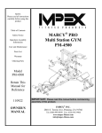
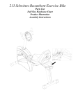
1
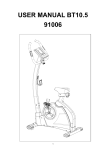
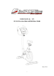
USER MANUAL CROSSTRAINER XT10.5 93004 Assembly Stage #1 1. Loose the pre-assembly screws on the front (J) and rear (J4) stabilizer. 2. Fasten front and rear stabilisers to the main frame using 2 carriage bolts (K2), nuts (K2) and washers (K1) for each one. After assembly, the Trainer can be adjusted to slightly uneven ground by adjusting the height of the foot caps at the back. The pre-assembled transportation wheels in the front allow easy manoeuvring of the Elliptical and therefore during assembly, need to be pointing down at the front (45°). Assembly Stage #2 1. Pull the computer and tension cable out of the handlebar post and before assembling Step 2. Please ensure the tension knob is at lightest position (minimum position). 2. Connect the tension cable (C3) by pushing the head into the notch of the cable (C3) coming from the main frame (see drawing). Connect the computer cables(C3 and F3). 3. First, loosen the pre-assembled screws. Then, put the upper cover(L) and handlebar post(C) into the main frame and fix it with 4 hexagon screws (F4). Assembly Stage #3 1. Disassemble one side of the pre-assembled screw on axle, insert the axle into the whole movable handlebars and handlebar post . Then tighten the end using one wave washer (K17), flat washer (K15) and screw (K18) in each side. 2 Assemble the bottle crag (L5) with screws (C5). Assembly Stage #4 1. Connect moveable handlebar and pedal arm. Use screw (K3), flat washers (K4),bushing and nylon nut (K5) to lock moveable handlebar and pedal arm in each side(E&E1). Assembly Stage #5 1. Assemble pedal arm cover, using cross screws (E8 & K20) to lock cover for pedal arm (L1) (L2). 2. Put left pedal(L3) onto the pedal arm and tighten it, using 2 dimple screws (K9), flat washers (K6), spring washers (K8) and bolts(K10) in each side Please note that the left and right pedals need to be placed in identical positions. Assembly Stage #6 1.Put the right and left upper movable handlebar (D4)(D5). Handlebars into the upright tubes and tighten it with bolt (K19) , washer (K2) and nut (K16). Assembly Stage #7 1. Mount the fixing handlebar (B) onto the handlebar post and tighten the cover for handlebar post with screws (K14) and washers (K12). Assembly Stage #8 1. Mount the fixing the computer(A) on the plate with 4 screws(A-1). Exploded drawing. Parts List Part no. A Description Q’ty Computer 1PCS Screw M5*10 for Computer 4PCS Front handlebar 1PCS B-1 Foam grip for front handlebar 2PCS B-2 Hand pulse set 1SET B-3 Hand pulse wire 1PCS B-4 End cap for front handlebar 2PCS B-5 Screw M3x20L 2PCS Hand post 1PCS C-2 Alex for handlebar 1PCS C-3 Computer cable (Upper) 1PCS C-4 Screw M5x30L 2PCS C-5 2PCS C-6 Screw M5xP0.8x20L Flat washerφ8*φ19*2T C-7 Spring washerφ8 4PCS C-8 Screw M8*P1.25*16L(6m/m) 4PCS Lower moveable handlebar (right) set 1SET D-1 Lower moveable handlebar (left) set 1SET D-3 Foam grip for moveable handlebar (Upper) 2SET D-4 Upper handlebar (right) 1PCS D-5 Upper handlebar (left) D-6 End cap for upper moveable handlebar 2PCS Pedal arm ( right) set 1SET 1SET E-4 Pedal arm ( left) set Flat Washerφ8.5xφ25x3T 2PCS E-5 Spring washerφ8*φ14*2T 2PCS E-6 Screw M8*P1.25*16L(6m/m) 2PCS E-7 Cap for pedal arm 2PCS E-8 Screw M5xP0.8x14L 8PCS F Main Frame 1PCS F-1 Sensor box 1PCS F-2 Screw M4x10L 1PCS F-4 Screw M5xP0.8x14L 1PCS A-1 B C D E E-1 4PCS 1PCS F-5 Adaptor 1PCS F-6 DC wire 1PCS G Shaft set 1PCS G-1 Screw M8xP1.25x12Lx5t 3PCS G-2 Bearing 6004RS 2PCS G-3 Big pulley wheel 1PCS G-4 Belts 1PCS G-5 Cap for disc 1PCS G-6 Pattern nut M10xP1.25x10T 2PCS G-7 Disk 2PCS G-8 2PCS G-9 Cross frame Flat washerφ5xφ16x1t G-10 Screw M4x14L 8PCS G-11 Screw M5x16L 6SET G-12 Screw M4x50L 5PCS G-13 Left chain cover 1PCS G-14 1PCS G-15 C type ring Flat washerφ20.3xφ30x1t G-16 Wave washerφ20xφ30x0.3t 1PCS G-17 Right chain cover Sleeveφ20xφ26x5.3mmL 1PCS Fly wheel set 1SET Magnetic system with gear box set 1SET Front stabilizer 1PCS J-1 Adjustment end cap 1PCS J-2 Screw 3/16"(#10)x3/4" 2PCS J-3 Adjustment end cap 1PCS J-4 Rear stabilizer 1PCS J-5 Adjustment end cap (small) 2PCS J-6 Nut 3/8"-16x3t 2PCS J-7 Adjustment end cap 1PCS 4PCS K-1 Screw M8xP1.25x55L Flat washerφ8*φ19*2T K-2 Nut M8 8PCS K-3 2PCS K-4 Screw M8xP1.25x55L Flat washerφ8xφ16x1t K-5 Nylon nut M8 2PCS G-18 H~H-8 I~I-8 J K 8PCS 1PCS 1PCS 4PCS 2PCS K-6 Bushingφ7xφ12x30mmL 4PCS K-7 Flat washerφ6xφ13x1t 8PCS K-8 Spring washerφ6 8PCS K-9 Knob for pedal 8PCS K-10 Screw M6xP1.0x50L 8PCS K-11 1PCS K-12 Metal cover for hand post Flat washerφ7xφ12x1t K-13 Spring washerφ7x2t 2PCS K-14 2PCS K-15 Screw M7xP1.0x30L Wave washer φ17.5xφ25x0.3t K-16 Curved Washers φ8xφ19x2t 4PCS K-17 Washer 2PCS K-18 Screw M8xP1.0x30L 2PCS K-19 Screw M8xP1.25x40L 4PCS K-20 Screw M3x25L 2PCS Cover for hand post 1PCS L-1 Cover (L) for pedal arm 2PCS L-2 Cover (R) for pedal arm 2PCS L-3 Pedal(LEFT) 1PCS L-4 Pedal(RIGHT) 1PCS L-5 Water bottle 1PCS L-6 Cover for handlebar 1PCS Idler set 1PCS L M~M9 2PCS 2PCS KIT XT10.5 K-16: Curved Washer 8* 9*2T (4) K-2:Acorn Nut for M8 Bolt (8) K-6:Bushing K-9: Knob (foot pedal)M6*P1.0 (8) K-4: flat washer 8* 16*1T (2) K-5: lock nut for M8 (2) K-3: allen bolt M8*P1.25*55L (2) K-7: flat washer 6* 13*1T (8) 7* 12*30L (4) K-8:Spring Washer for K-15: Curved Washer 17.5* 25*0.3T (2) handlebarboltφ6(8) K-1:flat washer 8* 19*2T (4) XT10.5 K:Carriage Bolt M8*P1.25*55L (4) K-11:Metal cover (1) K-17: flat washer 8.2* 50.8*6.6T (2) K-12: flat washer 7* *1T (2) K-10:Carriage Bolt M6*P1.0*50L (8) K-18: allen bolt M8*P1.0*30L (2) K-20:Screws M3*25L Black (2) K-13: Spring Washer for handlebarbolt φ7*2T(2) Allen Key(2) K-14: Allen Bolt M7*P1.0*30L(2) K-19: Carriage Bolt M8*P1.25*40L (4) Box Spanner (1) INSTRUCTION MANUAL OF SM2704-67 BUTTON FUNCTION: In stop mode, the mode is to confirm all exercise data setting, and enter into program. MODE/ENTER In stop mode, press the button back to main menu. RESET To start or stop exercise. START/STOP To test hear rate recovery status. RECOVERY To select training mode and adjust function value up. UP To select training mode and adjust function value down. DOWN For body fat measurement BODY FAT DISPLAY EXERCISE DATA: TIME Display range 0:00~99:99 ; Setting range 0:00~99:00 DISTANCE Display range 0.00~99.99 ; Setting range 0.00~99.90km CALORIES Display range 0~9999 ; Setting range 0.00~9990 PULSE Display range P-30~240 ; Setting range 0-30~240 WATT Display range 0~999 ; Setting range 10~350 SPEED 0~99.9km RPM 0~999 OPERATION PROCEDURE 1. Connect power supply and computer will power on with a long beep sound, LCD display all segments for 2 seconds and enter into personal data setting mode (gender, age, height and weight) for U1~U4. (drawing A~F) 2. After user data set up, computer will display main menu (drawing G). A C D B E F G 3. In main menu, first exercise program MANUAL will flash, user may press UP and DOWN button to select MANUAL PROGRAM (12 profiles) USER PROGRAMHRCWATT. (Drawing H~K) H I J K 4. Quick Start and Manual : Before exercise in Manual mode, user my set up TIME, DISTANCE, CALORIES and PULSE target. After power on, user may press START/STOP button to start exercise in MANUAL immediately without any setting. Level can be adjusted during exercise by press UP or DOWN. 5. PROGRAM: Before exercise in Program mode, user may set up TIME target. Press UP and DOWN to select Program with 12 profiles and press ENTER/MODE to confirm. Level can be adjusted during exercise by press UP or DOWN. 6. H.R.C.: Before exercise, computer will ask for user AGE first to calculate TARGET pulse. User may still press UP and DOWN to change target pulse from 30 to 240. 7. USER PROGRAM: User may press UP, DOWN and then press MODE to create his own profile. (from column 1 to column 20) User may hold on pressing MODE button for 2 seconds to quit profile setting. 8. WATT : The preset watt value 120 is flashing on screen in WATT setting mode. User may use UP, DOWN button to set target value from 10 to 350. Press MODE button for confirm. 9. RECOVERY : After exercising for a period of time, keep holding on handgrips and press “RECOVERY” button. All function display will stop except “TIME” starts counting down from 00:60 to 00:00. Screen will display your heart rate recovery status with the F1,F2….to F6. F1 is the best, F6 F6 is the worst. User may keep exercising to improve the heart rate recovery status. (Press the RECOVERY button again to return the main display.) 10. BODY FAT: 10-1 In STOP mode, press the BODY FAT button to start body fat measurement. 10-2 Then selected user (U1~U9) will blinking for 2 seconds. Then start measuring. 10-3 During measuring, user have to hold both hands on the handgrip. And the LCD will display “--” “--“ for 8 seconds until computer finish measuring. 10-4 LCD will display BODY FAT advice symbol, BODY FAT percentage, BMI for 30 seconds. NOTE: 1. This computer require 9V, 0.5mA adaptor. 2. When user stop pedaling for 4 minutes, computer will enter into power save mode, all setting and exercise data will stored until user start exercise again. 3. When computer act abnormal, please plug out the adaptor and plug in again. Exercise Computer ST2780 BUTTON FUNCTION: MODE/ENTER In stop mode, the mode is to confirm all exercise data setting, and enter into prog RESET In stop mode, press the button back to main menu. START/STOP To start or stop exercise. RECOVERY To test hear rate recovery status. UP To select training mode and adjust function value up. DOWN To select training mode and adjust function value down. BODY FAT For body fat measurement DISPLAY EXERCISE DATA: TIME Display range 0:00~99:99 ; Setting range 0:00~99:00 DISTANCE Display range 0.00~99.99 ; Setting range 0.00~99.90km CALORIES Display range 0~9999 ; Setting range 0.00~9990 PULSE Display range P-30~240 ; Setting range 0-30~240 WATT Display range 0~999 ; Setting range 10~350 SPEED 0~99.9km RPM 0~999 OPERATION PROCEDURE 9. Connect power supply and computer will power on with a long beep sound, LCD display all segments (drawing A) for 2 seconds and enter into personal data setting mode (gender, age, height and weight) for U1~U4. (drawing B~C) 10. After user data set up, computer will display main menu (drawing D). A B C D 11. In main menu, first exercise program MANUAL will flash, user may press UP and DOWN button to select MANUAL PROGRAM (12 profiles) (drawing E)PROGRAMUSER PROGRAMHRCWATT. 圖5 圖6 12. Quick Start and Manual : Before exercise in Manual mode, user my set up TIME, DISTANCE, CALORIES and PULSE target. After power on, user may press START/STOP button to start exercise in MANUAL immediately without any setting. Level can be adjusted during exercise by press UP or DOWN. 13. PROGRAM: Before exercise in Program mode, user may set up TIME target. Press UP and DOWN to select Program with 12 profiles and press ENTER/MODE to confirm. Level can be adjusted during exercise by press UP or DOWN. 14. H.R.C.: Before exercise, computer will ask for user AGE first to calculate TARGET pulse. User may still press UP and DOWN to change target pulse from 30 to 240. 15. USER PROGRAM: User may press UP, DOWN and then press MODE to create his own profile. (from column 1 to column 20) User may hold on pressing MODE button for 2 seconds to quit profile setting. 16. WATT : The preset watt value 120 is flashing on screen in WATT setting mode. User may use UP, DOWN button to set target value from 10 to 350. Press MODE button for confirm. 17. BODY FAT: 9-1 In STOP mode, press the BODY FAT button to start body fat measurement. 9-2 Then selected user (U1~U4) will blinking for 2 seconds. Then start measuring. 9-3 During measuring, user have to hold both hands on the handgrip. And the LCD will display “--” “--“ for 8 seconds until computer finish measuring. 9-4 LCD will display BODY FAT advice symbol, BODY FAT percentage, BMR, BMI for 30 seconds. 10. RECOVERY : After exercising for a period of time, keep holding on handgrips and press “RECOVERY” button. All function display will stop except “TIME” starts counting down from 00:60 to 00:00. Screen will display your heart rate recovery status with the F1,F2….to F6. F1 is the best, F6 F6 is the worst. User may keep exercising to improve the heart rate recovery status. (Press the RECOVERY button again to return the main display.) NOTE: 4. This computer require 9V, 0.5mA adaptor. 5. When user stop pedaling for 4 minutes, computer will enter into power save mode, all setting and exercise data will stored until user start exercise again. 6. When computer act abnormal, please plug out the adaptor and plug in again. Website: www.cross-ir.com/