1
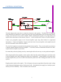
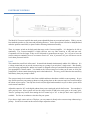
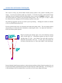
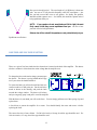
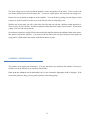
Sanders Sound Systems Model 10b Electrostatic Speaker System OWNERS MANUAL Table of Contents UNPACKING and ASSEMBLY ............................................................................... 2 POSITIONING ........................................................................................................... 4 ELECTRICAL CONNECTIONS .............................................................................. 5 ELECTRONIC CONTROLS ..................................................................................... 7 Level ............................................................................................................................ 7 Up/down Arrows......................................................................................................... 8 Midrange ..................................................................................................................... 8 Bass ............................................................................................................................. 8 Loss of Power.............................................................................................................. 8 ESL/WOOFER PHASING......................................................................................... 9 ADVANCED POSITIONING TECHNIQUES ...................................................... 10 LINE FUSE AND VOLTAGE SELECTOR ........................................................... 12 CLEANING / MAINTENANCE ............................................................................. 13 TROUBLESHOOTING ........................................................................................... 14 REMOTE CONTROL .............................................................................................. 17 SPECIFICATIONS................................................................................................... 18 SETTING UP YOUR SPEAKERS Setting up your new speakers is a three-part process that includes the following: Unpacking / Assembly / Positioning Electrical connections Adjustment of the balance between the woofers and electrostatic loudspeaker (ESL). UNPACKING and ASSEMBLY When you open the boxes, observe carefully how the packaging is arranged so you can repack items correctly in the future. When removing the woofer cabinets from their boxes, it is easier to lift the box off the speaker cabinet than to lift the cabinet out of the box. To do so, open the box and remove the roll of bubble wrap and the foam pad. Then roll the box over with the speaker in it, and lift the box up and away from the cabinet. The roll of bubble wrap contains the power cord, feet, cones, nuts, and screws. Be sure to unpack these items before discarding the bubble wrap. Begin assembly by turning the woofer cabinet on its back on a padded surface like a carpeted floor or a towel on a table. Never place the cabinet facedown (woofer down) as this will damage the woofer. 1) Attach either smooth feet or cones into the base of the cabinet. The smooth feet are for use on floors, while the sharp cones are for use on carpet. Speakers are not stable on carpet, so cones should be used to penetrate through the carpet and rest firmly on the floor below. You may prefer to install the smooth feet first, even on carpet, so you can easily move the speakers around to find the location you prefer. Then install the cones after you have decided on the ideal position. Both types of feet screw into steel inserts on the bottom of the speaker and can be adjusted by rotating them in or out to get the speaker level and stable. Lock nuts are provided to insure the feet or cones won't shift position or rattle. Put them on the threaded shaft of the foot or cone before screwing it into the bottom of the speaker. Once you have the feet or spikes adjusted to your satisfaction, gently tighten the nut against the bottom of the speaker to lock the foot or spike into position so it will not shift over time. 2 2) Attach the steel beams to the front edges of the woofer cabinet. Each beam is held in place by four socket-head screws that are in a small bag with an Allen wrench you can use to tighten them. Note that the side of the beams with the Velcro faces towards you (when you are looking at the front of the cabinet). Install the screws by first mounting them on the end of the Allen wrench. Then insert them through the hole in the Velcro side of the beam. The end of the screw will then stick through the beam where you can screw it into the cabinet. When the beams are secure, it is a simple matter to attach the electrostatic panels, grill, and trim to them using the Velcro that is already attached to these parts for your convenience. 3) Position the electrostatic panels approximately 1/4 of an inch (1/2 centimeter) above the top of the steel tubing. The edge of the panels should be flush with the sides of the beams. The panels' electrical connector hangs down near the left side of the woofer where you will see a mating connector on the woofer cabinet. The panels will only fit one way as if you try to install them backwards, the Velcro won't work. Because the panel is held with Velcro, you can remove and readjust its position to get it fitted correctly. 4) Plug the panel's electrical connector into its mate on the woofer cabinet. The connectors are keyed so that they will only fit one way so you cannot make a mistake. Note that the wires on the connector coming from the cabinet can be pulled out of the cabinet by several inches so you can easily position the connector. Adjust the connectors so that the connector will be hidden under the woofer grill and does not touch the woofer. Push any excess wire back inside the woofer cabinet. Should you ever want to disconnect the panel, you can unplug the connector. Just remember to press the little lever on the connector to disconnect the catch so you can pull the connectors apart. They come apart very easily — but only if you have released the catch. 5) Attach the woofer grill. It is held in place with Velcro like the panel. Press it firmly into the bottom of the electrostatic panel so there is no gap between the panel and the grill as you press it into place on the rails. See the photograph. 6) There are wood trim strips that run the full length of the beams. These fit with their narrow side facing forward and their wide side on the side of the speaker. These are symmetrical so fit either way. They are held in place with Velcro. 3 POSITIONING All speakers sound best when they are equidistant from you. Because the Model 10's imaging is so much more precise than conventional speakers, they will reveal errors in equidistant placement more than conventional speakers. The section of this manual called “Advanced Positioning Techniques” will assist you in obtaining the exact positioning needed. Aim the speakers directly at your listening location — do not place them parallel to the wall. Equidistant to speakers The speakers are designed to have a hard, reflective wall behind them — this will disperse the high frequencies throughout the room so they sound good when you are out of the sweet-spot. So do not put damping material on the wall behind the speakers unless you only listen at the sweet-spot and do not care about the sound when you are off-axis. The speakers may be positioned close to a wall — any wall, side or rear walls work equally well. You do not have to place them out in the room. Corner placement exaggerates undesirable bass and room resonances — it is best to avoid corner placement for speakers. The bass frequencies in all speakers are adversely affected by room acoustics. Depending on your room dimensions and the positions of the speakers, bass resonances will occur that cause ragged bass frequency response. This problem cannot be avoided — but it can be minimized by trying to produce an infinite number of infinitely small resonances instead of just a few large ones. Therefore, the worst bass will be produced with both speakers are positioned symmetrically in the room. This will have them at the same distances from walls and corners, which will cause them to produce the same two or three resonances and double their magnitude. It is much better to place the speakers randomly in the room so that they are each at different distances from walls and corners. This will produce more resonances at many frequencies and will reduce the magnitude of those resonances so the bass response will be smoother than symmetrical placement. You don't have to use random placement, you can place the speakers symmetrically (most listeners do), but symmetrical placement will compromise the smoothness of the bass. Random placement of the speakers refers only to their relationship to the walls and corners of the room. It does not apply to the relationship of the speakers to your listening location, which must always be set up so that the speakers are equidistant from you and pointed directly at you. 4 ELECTRICAL CONNECTIONS The block diagram above shows how to connect the electronics to the speakers. The Model 10b is bi-amplified, which means that two amplifiers are required, one to drive the woofers and another to drive the electrostatic panels. So that you do not have to buy a n extra amplifier, Sanders Sound Systems supplies a very high quality, bass amplifier in the same chassis as the electronic crossover — which is why the unit is called a “Crossover/amplifier.” Connect your preamplifier outputs to the Crossover/amplifier inputs using either balanced or single-ended interconnects. Connect the “High Pass” outputs on the back of the Crossover/amplifier to the amplifier that will drive the electrostatic section of the Eros speakers. The “Low Pass” outputs are not used when using the built-in bass amplifier. They are only used if you want to use a different amplifier than the built-in bass amplifier. To use them, connect an interconnect from the “Low Pass” outputs to the bass amplifier of your choice. Be certain that you have the phasing correct by connecting the cables the same way on each speaker and amplifier. When using the built-in bass amplifier, connect speaker cables from the speaker binding posts on the back of the Crossover/amplifier to the “Bass” binding posts on the rear of each speaker. Connect another set of speaker cables from the amplifier that you will use to drive the electrostatic panels to the “ESL” binding posts on the rear of the speakers. Plug the speakers into the wall receptacle. This will energize a tiny power supply that will produce a static voltage on the electrostatic diaphragms so they will play music loudly. Note that this power supply uses virtually no power and may be left on continually. There is no need to turn it on and off. 5 COMMENTS ON CABLES Surprisingly, some expensive interconnects are poorly designed in that they lack shielding. Avoid these as they often cause buzzing sounds or even allow radio stations to be produced through your speakers. Properly shielded interconnects will have an outer covering made of fine braided wire that forms a metal shield around the wire(s) inside the shield. This is known as coaxial wire. Always used shielded interconnects. Some speaker cable has very high capacitance and can cause high-quality, wide-bandwidth amplifiers to oscillate at very high frequencies. You cannot hear this oscillation as it is supersonic, but it will cause the amplifier to operate at full-power and can overheat and damage both the amplifier and the speakers. If you notice that one or both channels of any amplifier is running much hotter than normal, suspect a supersonic oscillation. One brand of cable is notorious for causing this problem and that is Goertz (Alpha core) cable. It is built as two thin ribbons sandwiched together, one on top of the other. Do not use this brand or type of cable on wide-bandwidth solid-state amplifiers (these are amplifiers that are capable of linear high frequency response to 100 KHz or beyond). You may use it on tube amplifiers because they have much more limited bandwidth and cannot reproduce the high frequencies where the oscillation occurs. But because electrostatic speakers are capacitors, it is best to avoid all high capacitance cables as this just taxes your amplifier more. Speaker cables exert most of their influence on the sound of speakers by interacting with passive, high-level crossovers present in most speaker systems to change the frequency response of the speaker. B ecause Sanders Sound Systems speakers do not have passive crossovers, cables will have little if any effect. The only basic requirement for the woofer cables is that they be large — at least 14 gauge, so that the amplifiers will not be isolated from their drivers by excessive impedance. Electrostatic speakers will operate best with cables that have extremely low inductance, moderately low capacitance, and moderately high impedance. Sanders Sound Systems manufactures cables that are ideal for this purpose, but most other cables will be satisfactory as l ong as t heir inductance is very low (excessive inductance will adversely affect the high frequency response of the speakers). You can find a d etailed discussion of this on the "Cable White Paper" found on the website www.sanderssoundsystems.com. Each speaker has an internal POWER SUPPLY to energize the electrostatic panels. T his is why each speaker must be plugged into the mains. You may use the supplied 10-foot power cord, or the any special power cord you prefer. Note that since the power supply is not involved in any audio circuits, there is no reason to believe that using a special cord or power conditioner would have any effect on the sound. COMMENTS ON AMPLIFIER POWER What good does it do t o have a wonderfully designed amplifier if it is usually overloaded and full of distortion? Power is the most important amplifier specification. While most of the power is required in the bass (which is why the included bass amplifier is very powerful), the electrostatic element requires a surprisingly large power amplifier at high frequencies because the impedance drops to 2 ohms. Therefore, it is best to drive it with at least a 60 watt/channel tube amplifier or a 250 watt/channel solid state amplifier. Low-power amplifiers will work, but they will cause distortion if you play them loudly on dynamic material. They may not sound obviously distorted, but they may sound “strained”, “harsh”, lack detail and dynamics, or have other audible flaws. Sanders Sound Systems strongly recommends very powerful amplifiers. 6 ELECTRONIC CONTROLS The Model 10 Crossover/amplifier has much greater adjustability than any conventional speaker. With it, you can best match the speakers to your room and personal preferences. Such a powerful tool can also be misadjusted and make the speakers sound awful, so please read the following information carefully: There is a m aster switch on the back panel that turns on the Crossover/amplifier. It is designed to be left on continually. T he Crossover/amplifier is highly efficient, uses very little electricity at idle, and runs cool. Components will last far longer if they are not subjected to repeated turn-on surges. So it is best to leave the crossover/amp on continually, there is no reason to turn it off. Also, if you turn it off, you will have to reset its levels when you turn it back on. Level This controls the overall level of the sound. It controls both channels simultaneously and has 100, 1 dB steps. It is a volume control and you can use the crossover/amp as a preamp if you only have a single source. But normally, you will be using a preamplifier, and the level control is designed so that you can obtain the optimum sensitivity of your preamplifier's volume control. You should set the Crossover/amp level so that you use most, or all of your preamplifier's volume control when playing music at the loudest level. This way, you will have the most sensitivity and linearity from your preamp's control. The crossover/amp's level control is the finest available and better than those available on most preamps. So you may find it best to turn your preamp up about to a loud position, then use the crossover/amp's level control to adjust the volume of your system. Not only does it work well, the digital readout makes it easy to see where you are and it can be remote controlled. Adjust this control to “90” on the digital readout when you are starting the unit for the first time. You can adjust it more precisely later. M ost systems will use the range from 80 ( 10 dB below unity gain) to 90 ( unity gain). "Passive" preamps may benefit from turning the level control up t o "99" so that you have more output level available. Feel free to use whatever value best fits your system. If you have a single source such as a CD player, you can connect it directly to the crossover/amp without using a preamp. Use the level control on the crossover/amp to adjust the volume. 7 Up/down Arrows These controls increase or decrease the level of the three functions to their left (BASS, MIDRANGE, and LEVEL). The digital readout shows the value you have selected. Midrange This is an extremely critical control. Adjust it so that the speaker's midrange is full and rich, but perfectly clear. If the speaker sounds too “thin”, you need to increase the midrange level. If the speaker sounds less than perfectly clear (“muddy”), then you have the midrange set too high — reduce it. This control is so important that often only one or two dB will be all the adjustment needed. There is no “right” or “correct” position for this control since its level depends on the sensitivity and power of your amplifiers. Turn it up to “90” as a starting point and then adjust it further based on listening to a wide variety of music over an extended period of time. This control can be very useful when you encounter poor source material (very common if you use your system for video). You can temporarily alter your “normal” midrange setting to make thin sounding material more rich and full. Conversely, if the source lacks high frequencies and clarity, you can turn the midrange down to improve detail and highs. After you have finished listening to the poor source material, you can then easily return to your normal setting using the digital readout. Because these settings can be done by remote control, you can easily get good sound from most any source material without even leaving your listening chair. Bass The bass adjustment allows you to trim the deep bass of the speaker to match the room acoustics. It is a well-known fact that rooms affect the bass performance of speakers tremendously. Even if a speaker has perfectly flat bass response in one room, it will not be flat in another. Also, it is sometimes desirable to alter the bass response to fit your taste. This control varies the bass response below 100 Hz over a 12 dB range. Start with the bass control at “4”. Add or subtract bass to your taste after you have obtained a reasonable setting for the midrange. Loss of Power If the unit loses power, the on-board micro-processor will have to “reboot” just like a small computer (which it is). All the settings will go to their “fail-safe” modes, which means all levels will be at zero. You will have to reset your preferred levels for Bass, Midrange, and Level before you will hear any music. So it is a good idea to write the values down where they are handy for the rare occasion when you might need them. 8 ESL/WOOFER PHASING The ESL and woofer leave the factory in-phase with each other when the ESL is driven by a non-inverting amplifier. Most amplifiers are non-inverting (a positive input signal produces a positive output signal, not a negative one). As long as you connect the positive (red) terminal of the ESL to the positive (also probably red) terminal on your amplifier, and the red terminals on the bass amplifier to the red terminals on the woofer, the ESL and woofer will be in-phase. If you have an inverting amplifier, the drivers will be out-of-phase when connected as described above. Out-of-phase drivers have a very subtle, adverse effect on the sound. Because you probably do not know if your amplifier(s) are inverting or not, it is best to test the system for phasing. First, listen to the speakers as they are currently wired. Then reverse the leads to either the ESLs or woofers (but not both), and listen carefully. Probably you will have to reverse the leads several times to hear any difference. If you do hear a difference, choose the phase that sounds the best to you. 9 ADVANCED POSITIONING TECHNIQUES This section is to help you position Sanders Sound Systems speakers so they produce incredibly precise images — far more precise than any other type of speaker. To do this, the speakers must be placed exactly equidistant from you so that the sound from each speaker arrives at your ears at exactly the same time. Also, each speaker needs to be aimed at your preferred listening location. This “sweet spot” or “focus” is where the sound will be best, although it will be satisfactory anywhere in the room. The following suggestions can help you achieve precise positioning. will be very helpful during this process. Although not essential, an assistant Place the speakers about where you want them and connect the speaker cables. The exact speaker position and geometry are critical and can be disturbed by connecting the cables. So connect the cables now — before you finalize speaker position. Begin by adjusting the listening angle. H ow wide should the listening angle (“sound stage”) be? Conventional speakers can only fill a listening-angle about 30° wide — their distance from each other can only be about half their distance from you. If wider, they will produce the well-known fault where there is a “hole-in-the-middle” of the sound image. Because Sanders Sound Systems speakers are phase-coherent and have a dipole dispersion pattern, they can be placed much further apart than most speakers and still completely fill the sound-stage. We encourage you to take advantage of this fact and place them very widely so you can enjoy a huge sound stage. 10 Sanders' speakers are deliberately made to be directional so that the sound quality is the most realistic possible. It is three-dimensional and has a “holographic” quality. Wide-dispersion speakers send most of their sound away from you into the room where it reflects off room surfaces before reaching you. You are actually listening to the room more than the speakers. B ecause these reflections travel varying distances before they reach you, they are delayed by varying amounts. When the speaker produces a transient sound (and music is mostly transient in nature), you hear the sound from many directions and at slightly different times. T his “smears” the transient and produces “muddy” sound and a poor image. Sanders' speakers direct the sound directly to you instead of throughout the room. You hear the speaker instead of the room. T his is why Sanders' speakers sound more clear than even very good conventional speakers. Sound clarity and image quality is a function of timing and distance. So to get the best performance, you will need to get your speakers precisely positioned. T his requires that you have both speakers an equal distance from you and that they are pointed directly at you. To avoid reflections from the wall behind you, it is best that your listening chair be well-away from the wall or that the wall has an absorbent surface in the area directly behind your head. This may seem like extra effort that is unique to Sanders' speakers, but this is not true. All speakers perform best when they are accurately positioned. Because wide-dispersion speakers confuse the sound from the speakers with the sound from the room, they are incapable of producing high-quality images. T herefore, errors in positioning are not as obvious as with Sanders' speakers. Position the base of each speaker equidistant from your ideal listening location. Y ou can use a tape measure, string, or thread to gauge the distance from your chair to each speaker. Use the center of the back or seat of your chair as one reference point and the inner edge of each speaker as the other. You can have an assistant at your chair hold one end of the tape or string while you check the distance to each speaker. Equidistant inner corners If you don't have an assistant, you can use a pin to hold the end of the string by sticking the pin in the center or back of your chair and tying the string or thread to it. The anchor point must be solid and stable to get accurate measurements! Next, adjust each speaker so it is pointed directly at your chair. Although you can do this by obtaining identical measurements to both lower corners of each speaker, an easier and more precise way to do this is to observe the reflection of a flashlight in the ESL diaphragms. Hold the flashlight just above your head while you search for its reflection. Center your reflection Get your reflection in both speakers centered from side-to-side while sitting in your listening chair. To avoid altering the previous measurement, pivot the speakers on their inner corners — the one you used as the reference point. When your reflection is centered side-to-side in both speakers, check to see that it is at the same height in both speakers. It doesn't have to be centered from top to bottom, but the reflection of your ears should be at least a foot from the bottom edge of the ESL. If not, the rear foot of the speaker can be screwed in or out to adjust the vertical angle of the speaker. the speakers should now be correctly positioned, but it is a good idea to double-check by measuring from your chair to your reflection in each speaker's electrostatic cell. 11 How precise should you be? The wavelength of a 10 KHz tone is about one inch. An error of 1/2" will place this frequency a full 180o out-of-phase — just like you had reversed the wires to one speaker. S o ideally, the speakers should be within a quarter wave — for 10 KHz, this would be a quarter inch of being equidistant from you. NOTE: If your speakers do not sound balanced (left to right), the most likely reason is that they are not equidistant from you. An error of one just inch will ruin left/right balance. Balance also will be ruined if the speakers are not pointed directly at you. Equidistant to reflections LINE FUSE AND VOLTAGE SELECTOR There are a pair of line fuses inside the fuse drawer that is located on the back of the amplifier. This drawer also has a window in it that shows the mains voltage that the amplifier uses. To change the fuses or the mains voltage you must open the drawer. The drawer is spring loaded and will pop out if you release the latch that holds it. To release the latch, you will need a small tool such as a small screwdriver or ball point pen. Put the tool in the notch as shown in the drawing, and push the latch towards the voltage window. The drawer will release and you can gently grasp it and pull it out of the amplifier. With the drawer in your hand, you will see the fuses. You can simply pull them out of their spring clips and replace them. A fuse blows to protect the amplifier for a reason. Y ou should identify the cause and correct it before replacing the fuses. The correct fuse size is 5mm x 20mm. For 200 volt circuits, a 10 amp, slow-blow type should be used. For 100 volt circuits, a 15 amp, slow-blow type should be used. 12 The mains voltage can be selected so that the amplifier can be used anywhere in the world. To do so, remove the fuse drawer and look inside where the drawer fits. You will see a white plastic "star" that shows the voltage on it. Remove this star by pulling it straight out of the amplifier. You can do this by putting your little finger or a ball point pen or small screwdriver into the recess on the left side of the star and pulling it out. With the star in your hand, you will see that it has four sides and each side has a different voltage printed on it. These are 100, 120, 220, and 240. Pick the one that best matches the mains voltage in your location. If your mains voltage is 230, use 240 volts on the star. Orient the star so that your voltage will face outward from the amplifier and show through the window in the drawer, then push it back into the amplifier. You can now slide the drawer back into place and press firmly against its spring until it is flush and the latch "snaps" and holds the drawer in place. CLEANING / MAINTENANCE The speakers do not require any maintenance. You may dust them as you would any fine furniture. You may use furniture wax on the cabinets as you would any fine furniture. Never spray any substance into the electrostatic cells, as the electrostatic diaphragms could be damaged. If the electrostatic panels are dusty, you may gently wipe them with a damp sponge. 13 TROUBLESHOOTING The speakers are rugged and reliable, and problems are extremely rare. This section is included to just make it easy to correct problems if they arise. ELECTROSTATIC AMPLIFIER FUSE-BLOWING — may be of two types. The first is where the amplifier blows fuses on loud music. The other is when it blows fuses the moment you turn it on. This will not occur in amplifiers that have a turn-on delay circuit, and is rare in modern amplifiers. Blowing fuses at turn-on is due to the fact that most amplifiers require a couple of seconds to stabilize their power supplied when turned on. When connected to an ESL, they may blow fuses only during this unstable period. To be sure, you first must check to be sure that it is just a simple turn-on instability problem and not a short-circuit or other amplifier problem. To test, disconnect one of the speaker wires from each channel. Then turn on the amplifier — it should not blow fuses with the speakers disconnected. If it does, the amplifier is defective. If it works properly, leave the amplifier on while you reconnect the speaker wires (being careful not to short the amplifier terminals with the loose wires). It should NOT blow fuses, and it should play music properly. If so, probably you can solve the problem by increasing the size of the fuses up t o the manufacturer's maximum allowed value. If despite larger fuses the problem persists, then you will have to connect the amplifier to the speakers through a delay relay (a delay of between 2 and 5 seconds is adequate). External, electronic delay relays are available from electronic parts houses, and your dealer probably can help install it. The amplifier manufacturer may be helpful as well. When playing music loudly through an ESL, even high quality amplifiers may blow fuses. If this occurs, consult the owner's manual, your dealer, or the manufacturer to find the largest fuse that is safe to use with your amplifier. R eplacing the stock one with a l arger one (within the safe range specified by the manufacturer) will often solve this problem. If it doesn't, you will need a more powerful amplifier. AMPLIFIER OVER-HEATING — should never occur. ESLs are “wattless” speakers. This means they don't dissipate your amplifier's power as heat like magnetic speakers do. Therefore, the amplifier should run cool — only a bit warmer than if it were just idling. If either channel of the amplifier runs hot, something is wrong. That “something” usually is supersonic oscillation caused by high-capacitance speaker cables or a defective component elsewhere in your system. DC offset in the output stages of the amplifier can also be a problem. This is not a speaker problem — it means there is a problem with the cables or in the electronics. Try changing cables. If that doesn't work, you will need to service the amplifier or other offending component. 14 TUBE AMPLIFIER OUTPUT IMPEDANCE — should be set as low as possible. As a minimum requirement, you must use the amplifier's 4• connection. If a lower one is available, us it. If your amplifier doesn't have a 4• (or lower) connection, it probably will not be suitable for driving electrostatic loads as it will tend to roll-off the high frequencies. AMPLIFIER INSTABILITY — can be a problem if the amplifier was designed to only drive resistive loads, not capacitive loads like electrostatic speakers. Oscillation may be noticed as a harsh quality in the high frequencies and/or amplifier overheating. If this happens, try a different amplifier. Be sure you are not using high capacitance speaker cables. If a d ifferent amplifier solves the problem, then your amplifier may need service. If different speaker cables solve the problem, then retire the problem-causing ones. MOMENTARY AMPLIFIER SHUT-DOWN — is caused by inappropriate activation of an amplifier's protection circuitry. You may experience this problem when playing music loudly and the amplifier completely shuts down for several seconds, then returns to normal operation — only to trip off again a few moments later. It will repeat the cycle as long as you try to play music loudly. The problem here is that the amplifier is not designed to drive low impedance, electrostatic loads. Although the amplifier may not seem to be harmed when it shuts down in this way, repeated activation may eventually lead to failure of the output transistors. You should switch to a different amplifier. BUZZING NOISES — are caused either by “ground loops” or unshielded interconnects. G round loops grounding problems with your equipment — most commonly your preamp. It is not a failing of any part of your system, it is simply an interaction. The problem usually is caused by having one or more components grounded to the mains circuit. Lifting the ground (by using a 3 pin to 2 pin adaptor on the power cable) often will stop the buzz. Also, it is good practice to have all components plugged into the same outlet strip. Surprisingly, some expensive interconnecting cables have no shielding. If lifting the mains ground doesn't stop the buzz, change interconnects. Be sure the test interconnect has a metal shield around a central conductor (“coaxial cable”). For testing at least, use an inexpensive cable because you can be sure they are properly designed and shielded. CROSSOVER/AMPLIFIER PROBLEMS — If one woofer fails to work, check the indicator lights on the front panel of the Crossover/amplifier. If both lights are on, then check the speaker fuses on the back of the unit. The fuse holder is the round unit between the speaker binding posts. To open the fuse holder, press in on the cap while you turn it ¼ turn counter-clockwise. It will release and you can remove it and the fuse for inspection. If the fuse appears blackened, or if the wire inside is broken, replace it. Some fuses are ceramic and you cannot see inside. If so, you will either need to measure the fuse with an ohm meter or substitute a new fuse to see if that solves the problem. A pair of spare amp fuses are supplied with the crossover/amp. 15 It is almost impossible to blow a amp fuse while playing music. So a blown fuse suggests that the problem was caused by shorting out the speaker cables while the amplifier is on. It is hard to avoid touching the cables together when changing them, so make it easy on y ourself (and the amplifier) by turning off the amplifier and waiting for the lights to fade out before changing speaker cables. If an indicator light is out, then that amplifier module may have failed. There are power supply fuses inside the amplifier, but these will usually blow only if a failure has occurred in the amplifier. So do not open the top and replace a blown fuse as it will almost surely just blow again. Instead, contact the factory for advice. Phone 303 838 8130. All contact information is on the website www.sanderssoundsystems.com. 16 REMOTE CONTROL The Crossover/amplifier may be operated by a remote control. operation. The remote comes pre-programmed for correct The “Bass”, “Midrange”, and “Level” function may directly be selected by the numbers 1, 2, or 3 on the keypad. Or you may sequence through them by repeatedly pressing the silver button in the middle of the upper cursor pad. The level of each of the functions may be increased or decreased by pressing either the Volume up/down keys or the Channel up/down keys. If you have a Sanders Sound Systems’ Remote Control Preamplifier, the Crossover/amplifier also can be operated by the remote control transmitter that comes with the preamp. The preamp's remote comes pre-programmed for crossover operation. Operation is done by first being sure that the word “AUDIO” appears at the top of the display. If the “MAIN” menu is on the screen, select “AUDIO” to get to the preamp's audio control screen. The crossover/amp control functions are on the second page of the “AUDIO” control screen. Press either the “pgup” or the “pgdn” button to get to the second page. On the second page, you will see “XOVER.” This is the Function Selector that will sequence through the three functions (Bass, Midrange, Level). When the appropriate indicator light is on, press the “Channel UP or DOWN” buttons to increase or decrease the level. Do not press the “Volume UP or DOWN” buttons as these control the preamplifier volume — use the Channel buttons instead. This is a very sophisticated, computer-controlled transmitter, into which you can put the IR codes from all your remotes and eliminate the pile of remotes that you now have to dig through every time you want to operate something. So don't waste it. Use it to control all your components from one unit. This is a truly amazing unit and you will be richly rewarded by reading its booklet and taking the time to program it. 17