1
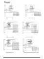
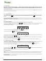
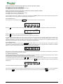
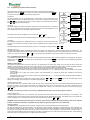
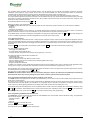
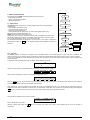
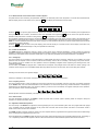
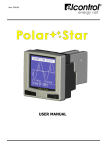
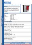
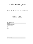
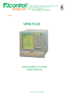
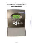
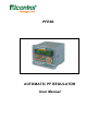
PFR96
AUTOMATIC PF REGULATOR
User Manual
Control of 5 banks Fig.1
Control of 10 banks Fig.3
Control of 12 banks
2
Fig.5
Control of 6 banks Fig.2
Control of 11 banks Fig.4
Connection of the Power Factor Correction CT Fig.6
ENGLISH - Instruction manual
1 - INTRODUCTION………………………………………. 4
2.1 - EC Declaration of Conformity ......................................................................................4
2.2 - Operator Safety ...........................................................................................................5
3 - POWER SUPPLY AND CONNECTION……………..5
3.1 - Power Supply ..............................................................................................................5
3.2 - Voltage Measurement .................................................................................................5
3.3 - Line Current Measurement ..........................................................................................5
3.4 - Power Factor Correction Current Measurement…5
4- START UP ……………………………………………... 5
4.1 - Initial Settings ..............................................................................................................6
4.1.1 - Language Selection...............................................................................................6
4.1.2 - Basic Programming ...............................................................................................6
4.1.3 - Setting the Desired Cosϕ.......................................................................................6
4.1.4 - Start-up Checks.....................................................................................................6
4.1.5 - Operating Test 1....................................................................................................7
4.2.1 - Programming the Measurement Parameters.........................................................8
4.2.3 - Alarm Programming...............................................................................................9
4.2.4 - Programming the Auxiliary Relays (for alarm signalling or fan control) .................9
4.2.5 - Programming the RS485 Communication Port......................................................9
5 - REGULATOR FUNCTIONS...………………….…10
5.1 - Measurement.............................................................................................................10
5.1.1 - Counters ..............................................................................................................10
5.1.2 - Measurements on the Power Factor Correction System .....................................11
5.2 - Control and Protection...............................................................................................11
5.2.1 - Voltage Dip .............................................................................................................11
5.2.2 - Frequency Control ..................................................................................................11
5.2.3 - Other Checks..........................................................................................................11
5.3 - Adjustment–Automatic Operation ..............................................................................11
5.4 - Adjustment–Manual Operation ..................................................................................12
6 - TECHNICAL FEATURES………………………12
6.1 - Constructive Characteristics ......................................................................................12
6.2 - Electrical and Operating Characteristics....................................................................12
6.3 - Environmental and Working Conditions.....................................................................12
7 - USE AND MAINTENANCE…………………….12
3
1 - INTRODUCTION
The PFR96 is a state-of-the-art device equipped with 16bit microprocessor for the control and the automatic adjustment of the reactive
power absorbed by the electric system; it enables the power factor correction of an average balanced three-phase line, by voltage and
current measurements referred to a single phase.
The standard measurement connection is of the type called ‘wattless’, but different connection modes may be set.
It can work without distinction on 50Hz and 60Hz mains, with admissible power supply/measurement voltage falling within a wide range
about the nominal value; the measurement may also be made using a voltage transformer. Current should be measured using an AT,
characterised by nominal secondary current of 5A and suitable power.
The PFR96 uninterruptedly controls the value of the reactive power circulating in the line and controls the outputs for keeping the cosϕ to
the preset value, with a high efficiency level. Connection and disconnection operations only occur for reactive power variations exceeding a
fraction of the power of the 1st step forming the power factor correction system and only if the intervention request lasts for a preset time.
The PFR96 can control the reactive power on the 4 quadrants to carry out the power factor correction of both loads and generators.
The PFR96 is equipped with a basic simplified programming page that enables low demanding users to start the instrument without the
need of setting the several data that the PFR96 can manage.
The PFR96 optimises the use of the power factor correction banks, balancing the operating hours thereof while trying to reach the preset
cosϕ in the shortest possible time and with the smallest number of manoeuvres (see Advanced Programming).
The PFR96 allows the setup of the status of each bank choosing between direct regulator control or always-on or always-off status, thus
eliminating the need of specific switches to be installed on the front of the control panel.
The PFR96 is equipped with a ‘recommended maintenance’ signalling system to inform the system manager that it is necessary to check
the power factor correction system components; the operating hour and manoeuvring number counters for each capacitor bank are
available on the display.
The PFR96 is equipped with a large number of outputs, 6 outputs or 12 outputs, of which 1 and 2 respectively can be associated to the
control of an external fan or to the signalling of abnormal conditions. The STATIC RELAY version is equipped with static relay outputs of
the zero crossing type to obtain a substantially endless life of the control device and a perfect control of the power contactor, with
consequent improvement of its performance.
The PFR96 is equipped with an internal thermal probe for the management of the ventilation of the panel housing the power factor
correction system and for the management of the automatic thermal overload protection procedures.
The plus version of the PFR96 is equipped with a second current input used to measure the current absorbed by a phase of the power
factor correction system; in this way, it is possible to directly control the harmonic stresses that affect the power factor correction system,
as well as its yield in terms of power.
The plus version of the PFR96 may be equipped with RS485 serial communication port with standard MODBUS RTU communication
protocol, thus allowing the operating parameters and the output status to be checked by a remote enquiry.
The PFR96 is equipped with a backlit alphanumerical display for complete display of measurements, anomalies and operating parameters.
The PFR96 displays the following measures: cosϕ, voltage, current, active and reactive power, voltage and current harmonic distortion,
working hours and number of manoeuvres for each bank.
The PFR96 is equipped with an easy level-based programming system for an intuitive management of the operating parameters.
The PFR96 is equipped with a page to select the display language of on-screen texts, where you may choose among 5 languages
(English, Italian, Spanish, French, German).
The PFR96 is equipped with removable terminal boards, with retaining screws for the signals coming from the AT and for the bank control
signals, so as to prevent any hazards related to the accidental release of the connectors.
The PFR96 is seated in a 96x96 flush-mounting container, made of shock-resistant plastic material.
The PFR96 features intelligent functions for the protection of capacitor banks in the event of a low power quality level.
2 - SAFETY
This instrument is designed and tested in conformity with the regulations and is supplied by the manufacturer in perfect technical safety
conditions. In order to maintain these conditions and ensure safe operation, the user should follow the instructions and the markings in
these use instructions.
•
Before connection, ensure that the operating voltage of the equipment and the mains voltage are the same.
•
The connection points may be powered; before performing any handling, maintenance or repairs, the instrument should be
disconnected from any power sources.
•
The capacitors inside the instrument may be charged even after the instrument has been disconnected from all power sources.
•
Ensure that any replacement guards are of the required type and nominal value. The use of repaired guards is forbidden. Once it has
been proven that safe operation is not possible anymore, the instrument should be taken out of service and ensured against
accidental use. Safe operation is not possible anymore in the following cases:
•
when the instrument exhibits clearly visible damages;
•
when the instrument is not working anymore;
•
after long storage under negative conditions;
•
after serious damages undergone during transport.
2.1 - EC Declaration of Conformity
Declaration of conformity to Directive EEC 89/336 (electromagnetic compatibility) and to directives EEC 73/23 and EEC 93/68 / modified
low voltage).
Manufacturer:
ELCONTROL ENERGY NET S.r.L.
Via Vizzano no. 44
40037 - Pontecchio Marconi (BO) - Italia
Product:
Automatic Power Factor Regulator PFR96
Reference standards EMC in industrial environments:
emission EN61326-1
Electrical safety
EN61010-1
Conformity:
EEC 89/336– EEC 72/23 – EEC 93/68
Mark affixing date: 2006
4
2.2 - Operator Safety
Read these pages carefully before installing and using this equipment.
The instrument described in this manual is intended to be used only by properly trained personnel. Any maintenance
and/or repair operations on the open instrument should be carried out only by qualified and authorised personnel.
For proper and safe use of the instrument and for maintenance and/or repair, the individuals in charge of maintenance and/or repair should
observe standard safety procedures.
Symbol affixed on the instrument or elsewhere means that reference should be made to the instruction manual.
3 - POWER SUPPLY AND CONNECTION
3.1 - Power Supply
The PFR96 regulator is equipped with two terminals for the power supply voltage. The nominal value of the active voltage is shown on the
back of the instrument, with a tolerance of +/-10%. Frequency may be, without distinction, 50Hz or 60Hz.
The PFR96 regulator is not equipped with internal fuse protection; two 200mA delayed fuses should therefore be added on the power
supply conductors.
Power the regulator through the terminals marked with V2-V3.
3.2 - Voltage Measurement
Voltage is measured through the same connection that refers to the power supply; the same limits and features therefore apply.
If the voltage to be measured is obtained through a potential transformer (PT), the nominal transformation ration should be input in the
programming, so as to make a correct adjustment.
3.3 - Line Current Measurement
The line current measurement (i.e., measurement of the total current absorbed by the system, correction capacitors included) is necessary;
for this reason, it is always provided on all PFR96 models; it must be made through an current transformer (CT) with nominal secondary
current of 5A. The value of the nominal primary current must be higher than the maximum value of current absorbed by the system to be
corrected, but not as high as to make the measurement unreliable for low loads; to this end, it may be convenient to note that the
amperometric sensitivity of the PFR96 is equal to 1/50 of the full scale (i.e., 100mA on the CT secondary circuit).
The CT used must be of good quality (class 1 minimum) and of suitable power (note that the amperometric loss of the PFR96 is equal to
1VA).
Connect the amperometric signal of the line current to the terminals marked with CS1-CS2.
In preparing the measurement circuit, note that the standard connection preset in the regulator requires the CT to be placed upstream of
both the load and the power factor correction device and connected to phase L1 (L2 and L3 are used for voltage measurement).
3.4 - Power Factor Correction Current Measurement
The plus version of the PFR96 regulator is equipped with an additional current measurement input for monitoring the consumption of the
power factor correction system. AS with the line current, also the power factor correction current measurement must be made through an
amperometric transformer (CT) with nominal secondary current of 5A. The primary current value should be selected taking into account a
value higher than the nominal current of the automatic power factor equipment. Such value must be less than the current absorbed by the
first bank of the power factor correction system multiplied by 50. The CT used must be of good quality (class 1 minimum) and of suitable
power (note that the amperometric loss of the PFR96 is equal to 1VA). Connect the amperometric signal of the power factor correction
current to the terminals marked with CS1-CS2.
3.5 - Control Outputs
The PFR96 regulator is equipped with a series of relay outputs (of the static type with zero crossing in the STATIC RELAYS version) for
the AC control of contactor reels.
There are 6 or 12 available outputs, all programmed to control the contactors; 1 or 2 outputs may be re-programmed to control the
ventilation or for alarm signalling purposes (respectively in the version with 6 and 12 outputs). The re-programmed outputs will not be
available to control capacitor banks. The control circuit requires a maximum switching voltage and current of 400V (230V in the STATIC
RELAYS version) with one common and one control for each contactor. Protect the control circuit using a delayed 4A fuse for the regulator
common(s).
Make the control and measurement circuit as shown in the figures listed below.
Control of 5 banks
Control of 6 banks
Control of 10 banks
Control of 11 banks
Control of 12 banks
Cap’s CT connection
see figure 1
see figure 2
see figure 3
see figure 4
see figure 5
see figure 6
4 - START-UP
The PFR96 regulator is designed to allow very easy start-up and operation.
In order to allow proper start-up, in the simplest cases, without having to set the several parameters that can be managed by the device
while allowing the most demanding users to control all the available parameters, the regulator programming is divided into two levels: basic
programming and advanced programming.
The basic programming only requires 2 functional system parameters.
The advanced programming manages several additional parameters intended for optimising the adjustment and control work of the
PFR96.
5
4.1 - Initial Settings
With reference to what described above (Section 3 – Power Supply and Connection), check that the electrical connections have been
made properly. Note that the CT for measuring the electrical system current must be placed upstream of both the load and the
power factor correction device and connected to phase L1 (L2 and L3 are used for voltage measurement). After these checks, the
regulator is ready to be started.
When it is started, the regulator displays the message “Elcontrol Energy Net” for 5 seconds; after that, the PFR96 model and the internal
firmware version are displayed for 5 seconds.
4.1.1 - Language Selection
Once the model and firmware version have been displayed, the regulator displays the language selection page; the active language is
shown flashing. Press the PAG key to scroll the list and select the desired language (flashing); press the SEL key to select, or wait 10
seconds.
After that, the instrument switches to warm up mode, which lasts 60 seconds and is displayed on the screen to prevent any operations on
the banks when the capacitors may still be loaded.
After 60 seconds, the regulator is ready for the adjustment operations. The programming may also be performed during the initial ‘warm up’
phase.
4.1.2 - Basic Programming
For proper start-up, only two basic parameters need to be set for a proper measurement and adjustment.
To access the programming page, press and hold + and - simultaneously for 3 seconds (access to programming causes the
disconnection of all connected banks and the adjustment lock, until you switch back to the automatic or manual operation mode).
The on-screen display changes into
S T ANDARD
CT
RAT I O
S E TUP
5 0 0 / 5 A
The original CT ratio is 500/5A; set the correct value pressing + or - .
To go to the next page, press PAG . The display changes into
S T ANDARD
S T EP
° 1
S E TUP
5 0 KVAR
The original power value of the 1st bank is 50kvar; set the correct value, referring to the technical documentation of the automatic power
factor equipment, if required, pressing + or - .
NOTE: the automatic determination of the first step was intentionally avoided since in the event of load variations during the acquisition
process, any regulator would determine the value incorrectly.
To exit the basic programming, press and hold the PAG key for three seconds; the initial measurement page will be displayed.
4.1.3 - Setting the Desired Cosϕ
This setting, only accessible if the regulator is set to automatic mode, allows the setting of the cosϕ to be maintained in the system. The
preset value is 0.94 inductive; such setting is correct in most cases; for this reason, this setting may be skipped.
If the user wants to change this parameter, while the regulator is in automatic mode, press and hold the PAG key for 3 seconds.
The on-screen display changes into the following.
COS ϕ T ARGE T SE T UP
COS ϕ = 0 , 9 4 I ND
To change the value, press + and/or - . At the end of the programming, press and hold PAG again for 3 second to exit the pages and
return to the previous operation.
NOTE: after 30 seconds, the regulator automatically switches back to standard operation.
4.1.4 - Start-up Checks
When switched on or when you exit the programming, the regulator switches to the (automatic or manual) operating mode that was set
before.
The operating mode set is displayed on the top right of the screen, with AUT meaning automatic mode and MAN meaning manual mode.
In the second line, the screen displays the measurements made by the regulator; the proper CT connection may be checked by analysing
the measured values.
The following table may be used as a reference.
6
System consisting of conventional loads, without any correction capacitors enabled.
The displayed cosϕ must have the IND message.
The displayed kW must not have the GENERATED message.
The displayed kvar must have the IND message.
System consisting of asynchronous generators, without any correction capacitors enabled.
The displayed cosϕ must have the IND message.
The displayed kW must have the GENERATED message.
The displayed kvar must have the IND message.
If such conditions are not met, check the CT signal; this is allowed by the PFR96 regulator through a specific programming page without
directly operating on the CT (see “Advanced Programming”, Paragraph 4.2.1).
4.1.5 - Operating Test 1
Set the regulator to manual mode pressing AUT/MAN (the screen displays “MAN” on the top right side).
+ + +
COS ϕ = 0
MA N
,
8 I ND
7
Press the + key; the bank status indicator will show the ON status at position 1; connect the corresponding capacitor control contactor.
+
COS ϕ = 0
MA N
,
8 I ND
7
Press the + key again to connect the remaining banks in a sequence.
Press the – key to progressively disconnect the active banks, starting from the first one.
The bank connection/disconnection must cause a change of the cosϕ read by the regulator; in particular, starting from the inductive cosϕ
condition, with the bank connection the value must increase (once 1 is reached, the value read decreases again but with the CAP
capacitive identification). If this does not happen, either the banks are not working (not powered) or the AT is placed downstream of the
power factor correction banks. If the test is successful, continue with the operating test 2.
4.1.6 - Operating Test 2
Set the regulator to automatic mode pressing AUT/MAN (the screen displays “AUT” on the top right side). If the regulator is properly
connected, the measurements give an inductive cosϕ and a positive active power value kW. If the load power is sufficient, the regulator
displays an up arrow meaning that the automatic step connection procedure has started;
AUT
COS ϕ = 0
,
8 I ND
7
the connection continues until the measured cosϕ is close to the value set (default value: 0.94 inductive). No indications in the last box of
the first line on the screen denotes a balance condition.
4.2 - Advanced Programming
The basic programming described in Paragraph 4.1.2 is sufficient for a proper adjustment. The advanced programming section contains
several additional parameters to optimise and customise the device operation.
For a simple use of the regulator, setting these parameters is not required as they are factory preset.
To access this programming, press and hold the + and - simultaneously for 3 seconds while the regulator is on. The on-screen display
changes into the basic CT setup and first bank power pages. Press the PAG key again to display the page to access the advanced
programming.
ADVANCED S E TUP
S E L
T O ENT ER
To access the advanced programming, press the SEL key.
The advanced programming menu structure is as described below; to go to the next menu, press the PAG key; to open the displayed
menu, press the SEL key; to exit the displayed menu and return to the previous level, press and hold the PAG key for 3 seconds.
7
4.2.1 - Programming the Measurement Parameters
The measurement programming menu allows the setup of some measurement-related
parameters. Press the PAG key to proceed with a new parameter, press and hold PAG for
3 seconds to exit the measurement parameter programming.
CT Direction
The first parameter that can be programmed is the direction of the amperometric signal
coming from the main CT; the default value is direct, which can be changed into reverse using
the + and - keys. This allows the correction of the CT direction, thus eliminating the need of
physically modifying the assembly/wiring.
CT Phase
This is the setting of the phase to be used to measure the current through the CT. The default
value is L1, assuming that the voltage is measured through the signal between the two
remaining phases (L2 and L3), making a wattless connection.
PAG 3''
Measurement
paramete
programming
SEL
Main CT direction and Phase
PT ratio
Ratio of power factor
correction AT
PAG
SEL
Adjustment
programming
Active banks
Discharge and delay time
Bank status and power
PAG 3''
PAG
PAG 3''
SEL
Alarm
programming
RMS voltage and peak
threshold
Harmonic threshold
Temperature threshold
PAG
PAG 3''
SEL
The default value may be changed into L2 or L3 using the + and - keys.
This selection eliminates the need of disassembling the CT to place it on a different phase.
Auxiliary
Relay
programming
Auxiliary relay
function
PAG
PAG 3''
SEL
RS485
programmin
g
CT Setting
If the regulator is powered by a voltage transformer, it is possible to set its transformation ratio
(of course, the transformer secondary voltage must be compatible with the regulator nominal
voltage).
The default setting does not require the presence of the CT; the setting is changed pressing + and - .
Communication
parameters
PAG
Setting the Cap’s CT
The plus type regulator allows measuring the current of a phase of the power factor correction system through a dedicated CT. The
measures associated thereto and the relevant controls are available in the automatic process. The transformation ratio of the power factor
correction CT may be set using the + and - keys; a value below 5/5A disables the power factor correction measurement function.
4.2.2 - Programming the Adjustment
The adjustment programming menu allows the setup of the parameters required to obtain optimum adjustment, compatible with the system
features. Press the PAG key to proceed with a new parameter, press and hold PAG for 3 seconds to exit the adjustment parameter
programming.
Number of Active Banks
The regulator is equipped with a number of relays (6 or 12) depending on the model; such relays may all or partly be used to control the
capacitor connecting devices. Some relays may also be used to control a forced ventilation system and/or for alarm signalling. However,
since the step control activity has priority, only unused AUX type relays should be used for the optional control.
The regulator has a default programming of the number of banks equal to the number of relays provided on the instrument;
if the regulator has 6 relays, the number of banks may be decreased (5, 4, 3, 2) leaving the AUX1 relay available for the optional
programming;
if the regulator has 12 relays, the number of banks may be decreased to 11, leaving the AUX2 relay available for the optional
programming;
if the regulator has 12 relays, the number of banks may be decreased (10, 9, …, 2), leaving the AUX1 and AUX2 relays available for
the optional programming.
Set a number of active banks equal to their actual number, using the + and - keys; press PAG to go to the next parameter e briefly
display the availability of the AUX relays for the optional programming.
Capacitor Discharge Time
The capacitors must have a residual voltage of less than 10% of the nominal value before they are powered; dedicated discharge devices
(resistors or reactors) are provided, which operate in a predetermined time; this is the discharge time. The value normally used is 30
seconds; such value is factory preset. The value may be changed from a minimum of 5 second to a maximum of 300 seconds using the
+ and - keys.
WARNING: it is necessary to set the correct value, compatible with the system used to discharge the capacitors.
Capacitor Delay Time
To avoid useless manoeuvres on the capacitors, both connection and disconnection times should be delayed by a few seconds. The
manoeuvring time is the time the insertion signal must remain active for the adjustment to be made. The default value is 30 seconds, the
minimum settable value is 5 seconds, the maximum value is 300 seconds, using the + and - keys.
WARNING: before decreasing the time below 30 seconds, check that the maximum manoeuvre frequency that can be obtained
(number of switches per minute) is compatible with the manoeuvring devices (capacitor control contactors).
Adjustment Method
The PFR96 regulator is equipped with two automatic operating modes: geometrical method and equalized method.
The default configuration is geometrica method. The adjustment is performed with connections and disconnections, always starting from
the lower-order banks available for the operation. The geometrical logic exhibits the advantage of being foreseeable in its operation and
only requires the setting, in the basic setup, of the power of the first bank. In the composition of the power factor correction system, a
proper geometrical adjustment requires the banks to be made by associating the one of the lowest power to the first step, and the following
ones of the same or increasing power to a multiple value of the first bank.
8
The equalized method combines several important features, and the following goal is achieved: the regulator manoeuvres the banks
irrespective of their sequence, trying to obtain the set cosϕ in the shortest possible time, and with the lowest number of manoeuvres,
compatibly with the discharge times and giving priority to the batteries with a lower number of working hours.
An even system wear level is thus obtained, keeping under control the ageing parameters of the capacitors/contactors of each bank.
The proper balanced adjustment requires the first bank to be associated to the unit of the lowest power and the following banks to be made
with powers of increasing value/equal to the previous one, with a multiple value of the first bank. The power of each bank, moreover, must
be known and set in the advanced setup.
Set the desired adjustment method using + and - .
Managing the Status of the Single Banks
The PFR96 regulator allows the setup of the operating status for each active bank, except for the first one. Three modes are available:
- always on,
- always off,
- managed by the regulator.
This feature allows to setup a bank as always on, for example with the MV/LV transformer power factor correction function, or a bank that
requires maintenance and thus, must not be activated, may be excluded from the regulator controlled operation.
In the default setting, each bank is managed by the regulator according to the programming made; the + and - keys allow selecting ON
or OFF. The status programmed in each bank is applied both in automatic and in manual mode.
4.2.3 - Alarm Programming
The PFR96 regulator can control and intervene in a large number of dangerous events. Some events are regarded as dangerous when the
value of the associated parameter continuously exceeds the threshold set for a preset time (120 seconds); the alarm condition ends when
the associated parameter drops below the trigger threshold reduced by a hysteresis equal to 2% of the alarm value, continuously and for a
preset time.
Press the PAG key to proceed with a new parameter, press and hold PAG for 3 seconds to exit the alarm programming.
The alarm condition triggering causes:
- quick trigger of all active banks
- on-screen display of the triggered alarm
- closing of the alarm relay (if set in the auxiliary relay programming – see 5.2.4).
The parameters that can generate alarm conditions are:
- voltage RMS value,
- instant voltage peak value,
- harmonic distortion (THD) of the electrical system current,
- harmonic distortion of the current circulating in the capacitors (plus versions only),
- harmonic voltage distortion,
- dangerous temperature threshold.
In addition, it is possible to set the temperature threshold to start the forced ventilation, which does not cause the bank trigger/alarm relay
closing, but the closing of the auxiliary relay associated to the start of the forced ventilation (if programmed – see 4.2.4).
Alarm thresholds have a factory preset value that usually allows an effective control of the power factor correction system/mains; however,
such thresholds may be changed using the + and - keys.
The value set to 0 / OFF disables the corresponding alarm.
WARNING: the alarm threshold values must be assessed and changed, if required, by authorised and qualified personnel. Wrong
alarm threshold values may seriously damage the power factor correction system and the electrical system.
4.2.4 - Programming the Auxiliary Relays (for alarm signalling or fan control)
The PFR96 regulator is equipped with an auxiliary relay (called AUX1) in the 6 output version and two auxiliary relays (called AUX1 and
AUX2) in the 12 output version.
Such relays, of the normally open type and each equipped with two dedicated terminals connected to the terminal board, may be used to
control power factor correction banks or an external fan, or for signalling alarms in progress. The possibility of using the auxiliary relay(s)
for fan control or for alarm signalling depends on the setting of the number of banks to be controlled (Par. 5.2.2).
If the auxiliary relays are associated to the control of capacitor banks, access to this menu displays (NOT AVAILABLE); otherwise, using
+ and - it is possible to select between the fan control function and the alarm signalling function. Press the PAG key to proceed with
the following auxiliary relay, press and hold PAG for 3 seconds to exit the auxiliary relay programming.
4.2.5 - Programming the RS485 Communication Port
The PFR96 plus regulator is equipped with RS485 port with MODBUS RTU communication protocol with BCD coding. The parameters
that can be set using the + and - keys are:
- Instrument address
- baud rate
- parity bit.
Press the PAG key to proceed with a new
parameter, press and hold PAG for 3 seconds
to exit the RS485 communication parameter programming.
9
5 - REGULATOR FUNCTIONS
Cosϕ display
The operation of the PFR96 automatic regulator allows carrying out:
- measurement operations
- control and protection operations
- adjustment operations.
PAG
Active power display
PAG
5.1 - Measurement
The PFR96 regulator refreshes the on-screen display every second; the parameters
measured are:
- mains voltage (real effective value),
- mains current (real effective value),
- instrument internal temperature,
- current absorbed by the power factor correction system (plus versions only).
With the directly measured parameters, the
PFR96 can process three-phase reactive and
active power value, load cosϕ, voltage and current THD. In the plus versions there are
also the data relating to the specific consumption of the power factor correction system,
that is, three-phase reactive power, current and current THD.
The measured parameters are displayed in the second line of the screen; to display the
next parameter, press the PAG key; the regulator displays all the available measures in a
sequence.
Reactiva power display
PAG
Voltage and current
PAG
Voltage and current THD display
Fan operation
and temperature
PAG
SEL
Access to
counters
PAG
Access to measurements
on power factor correction
system (Plus version only)
Operating hours
Number
of manoeuvres
SEL
Power
Current
Current THD
PAG
5.1.1 - Counters
The PFR96 regulator can measure and display some parameters related to the operating history of each bank and in particular, the
number of operating hours and the number of manoeuvres made (the relevant data are stored to the memory every 10 hours of activity).
In this way it is possible to monitor the ageing level of the main components of the power factor correction bank, that is, capacitors and
control contactors.
To display the bank operating data, open the specific menu displayed as follows
OP ERAT I O
S E L
T O
N
I NF O
ENT ER
Open the counters page to immediately display the number of operating hours of bank 1.
OP E R A T I N G T I ME
S T EP . 1
1 2 3 0 H
Wait 3 seconds to display the number of manoeuvres performed by bank 1.
T OT AL
I NS E R T I ONS
S T EP . 1
5 6 7 0 MA N
Press the PAG key to go to the next bank; press and hold the key for 3 seconds to return to the display of the mains cosϕ (this condition
is obtained automatically if no keys are pressed for 30 seconds).
When 5000 hours or 5000 manoeuvres are reached, the symbol of an adjustable spanner ‘Ψ’ is shown near the active bank symbol to
suggest the check of the components in order to carry out a preventive maintenance. The symbol may be cleared pressing and holding the
SEL key for 5 consecutive seconds when you are in the counter display page, at the step being examined.
The operation is displayed on the screen as follows
T OT AL
I NS E R T I ONS
Ψ ERASED
and it is displayed for 2 seconds.
Warning: pressing and holding the SEL key for 5 seconds more resets the counters of the operating hours and of the number of
manoeuvres.
10
5.1.2 - Measurements on the Power Factor Correction System
The plus versions allow measuring the parameters relating to the automatic power factor equipment. To access these measurements,
after the display of the counter access menu, press the PAG key to display the measurement access menu.
F C
S E L
EQP
T O
ME A S U R E
ENT ER
Press the SEL key to open the pages used for the power factor correction measurements; the value of the reactive power supplied at that
time by the power factor correction, the effective value of the absorbed current (pressing PAG ) and the value of the percent harmonic
distortion of the power factor correction current (pressing PAG ) are displayed in a sequence.
Such parameter indicates the real harmonic overload that must be sustained by the power factor correction system; this parameter can be
associated to an alarm/protection condition to control the harmonic overload aimed to protecting the system if the limits set are exceeded.
NOTE: for a correct measured value, the power factor correction CT ratio should be set (see 5.2.1) and the amperometric signal should be
connected as indicated in figure 6).
Press the PAG key again to return to the power display; press and hold the key for 3 seconds to return to the display of the mains cosϕ
(this condition is obtained automatically if no keys are pressed for 30 seconds).
5.2 - Control and Protection
The PFR96 regulator is designed to perform a series of cyclic checks of the measured parameters, in order to signal any abnormal
situations and protect the system from potentially dangerous operating conditions. A part of the parameters checked is associated to the
programming of thresholds and of intervention modes (see 4.2.3), while other parameters are checked irrespective of the settings.
5.2.1 - Voltage Dip
The mains voltage may be subject to micro-interruptions or sudden RMS value drops (commonly called dip); such condition may cause
problems since the capacitor control contactors could become unsteady, with the risk of uncertainty in the closing of the power contacts.
Such situation should be avoided since the capacitors would be repeatedly energised without respecting the discharge times, with
consequent damaging.
For this reason, the PFR96 is equipped with a measurement circuit/quick and privileged action that allows the instant opening of all
contactor control relays as soon as the RMS voltage value drops below 50% of the nominal value, with a 10ms delay (8ms at 60Hz).
Following such intervention, the regulator displays:
D I P
5 0 %
remaining in standby for 120 seconds; at the end of this time, the regulator resumes normal operation.
5.2.2 - Frequency Control
The mains voltage frequency value may differ from the nominal value and may be variable over time. Such value is constantly measured
by the PFR96, which uses it as internal standard for the calculations. An active check reports any excessive deviation of the frequency
measured from the admissible value; if the frequency differs by more than 5% from 50/60Hz, the regulator interrupts all the operations,
opens all capacitor control contacts and displays
WR O N G
F REQUENCY
Normal operation resumes automatically if the frequency returns within the admissible range.
5.2.3 - Other Checks
The other parameters managed by the PFR96 to check the power factor correction system operating status are subject to setup and
activation. For specific information, see 4.2.3.
5.3 - Adjustment–Automatic Operation
The main activity of the PFR96 is the adjustment, meaning keeping the cosϕ of the electrical system close to a programmed value (target
cosϕ), compatibly with the possible dynamics for the power factor correction and with the division into banks. The automatic mode is
shown on the screen with the “AUT” indication.
The PFR96 regulator constantly checks the system cosϕ and responds with the programmed times (capacitor intervention time/discharge
time), according to the programmed logic (see 4.2.2).
During the adjustment, the PFR96 provides the status of each bank, lighting the ╬ symbol at the connected capacitor banks. The lighting of
↓ or ↑ respectively means that the regulator is about to disconnect/connect one of the available capacitor banks from/to the mains.
11
5.4 - Adjustment–Manual Operation
The PFR96 regulator may be set to manual operating mode (indicated on the screen by the with the “MAN” indication). In this mode, the
regulator always makes the standard measurements, checks and protections, but does not autonomously operate on the banks to reach
the target cosϕ.
The banks may be manually connected and disconnected, using the + and - keys, always actuating a sequence that controls the banks
starting from the first one and proceeding to the next ones.
In the manual bank connection mode, the PFR96 can manage the discharge times; the regulator, therefore, may not connect a bank when
the + key is pressed. In this case, if the cause depends on the need of waiting for the capacitor to be discharged, the symbol of the bank
concerned flashes for a few seconds; wait for the discharge time to elapse and then, press the + key again to make the connection.
6 - TECHNICAL FEATURES
6.1 - Constructive Characteristics
Plastic container for panel mounting
Dimensions: front 96x96mm, depth 116mm
Cut-out template: 91x91mm
Maximum weight: 800g
2
Removable terminal board with nominal section of 2.5mm , IP20, with safety flanges (power supply terminal board excluded).
6.2 - Electrical and Operating Characteristics
Voltage power supply according to the model:
230V model: 215-250V ±10%
400V model: 380-440V ±10%
Voltage consumption: 10VA max
Amperometric power supply: 0.1-5A, maximum overload: 6A
Amperometric consumption: 1VA max
Frequency: 50/60Hz ±5%
Zero setting for voltage failure and mains loss.
Filter ensuring normal operation even in case of considerable line interference.
Cosϕ adjustment range from 0.7 inductive to 0.7 capacitive.
CT setting range: 5/5A to 5000/5A.
Minimum setting value of the first step power: 1kvar
Intervention time between steps: settable between 5sec and 300sec.
Capacitor discharge time: settable between 5sec and 300sec.
Number of output contacts according to the model:
- 6 output model: 5 NO relays with single common and 1 NO relay with two terminals
- 12 output model: 10 NO relays with two commons and 2 NO relay with two terminals
Contact capacity according to the model:
- model with electro-mechanical relay: 5A-250V / 2A-400V 50/60Hz
- model with static zero-crossing relay: 1A 230V 50/60Hz
Relay common capacity: 8A at 40°C
2
Removable contacts with nominal section of 2.5mm
Communication port (optional): RS485 – MODBUS RTU protocol with BCD coding
6.3 - Environmental and Working Conditions
Protection rating of front panel: IP40
Operating temperature range: -10+50°C, condensation not allowed
Storage temperature: -25+70°C
Indoor installation away from heat sources and from direct sunlight.
7 - USE AND MAINTENANCE
For a proper use and maintenance of both regulator and operating system, please note the following:
keep all parts thoroughly clean,
make sure all terminals are tight,
remedy or replace any faulty parts or connections,
carry out maintenance operations during installation and then, every 3 months.
12