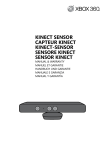
1
404 416
Max Air Surfaces
Installation Manual
Document Revision: A
Part Number: 840-11316-01
Release Date: August 2010
Euphonix is Avid. Learn more at www.avid.com
Regulatory and Safety Notices
FCC Notice
Part 15 of the Federal Communication Commission Rules and Regulations has established Radio
Frequency (RF) emission limits to provide an interference free radio frequency spectrum. Many
electronic devices produce RF energy incidental to their intended purpose.
These rules place electronic equipment into two classes, A and B, depending on the intended use.
Class A devices are those that may be expected to be installed in a business or commercial environment.
Class B devices are those that may be expected to be installed in a home or residential environment. The
FCC requires devices in both classes to be labeled with the interference likelihood and additional
operating instructions. The rating label on the equipment will show which class the product is (A or B).
Class A product will not have an FCC logo. Class B equipment will have an FCC logo. The information
statements differ on the two classes.
Class A Equipment
This equipment has been tested and found to comply with the limits for a Class A digital device,
pursuant to Part 15 of the FCC rules. These limits are designed to provide reasonable protection against
harmful interference when the equipment is operated in a commercial environment. This equipment
generates, uses, and can radiate radio frequency energy and, if not installed and used in accordance
with the instructions, may cause harmful interference to radio communications. Operation of this
equipment in a residential area is likely to cause harmful interference, in which case the user will be
required to correct the interference at personal expense.
Euphonix is Avid. Learn more at www.avid.com
Modifications
The FCC requires the user to be notified that any changes or modifications made to Avid hardware that
are not expressly approved by Avid Technology may void the user’s authority to operate the equipment.
Cables
Connections to Avid hardware must be made with shielded cables with metallic RFI/EMI connector
hoods in order to maintain compliance with FCC Rules and Regulations.
PRODUCTS WITH MULTIPLE POWER INPUTS:
WARNING: Each power input is intended to be connected to a separate branch circuit. Risk of high
leakage exists if multiple inputs are connected to a single source and protective earth is not present. A
QUALIFIED SERVICE PERSON shall verify that each socket-outlet from which the equipment is to be
powered provides a connection to the building protective earth. If any do not provide this connection,
the QUALIFIED SERVICE PERSON shall arrange for the installation of a PROTECTIVE EARTHING
CONDUCTOR from the separate protective earthing terminal to the protective earth wire in the building.
Canadian ICES-003
Class A Equipment
This Class A digital apparatus meets all requirements of the Canadian Interference-Causing Equipment
Regulations.
Cet appareil numérique de la classe A respecté toutes les exigences du Règlement sur le matériel
brouilleur du Canada.
Euphonix is Avid. Learn more at www.avid.com
European Union Declaration of Conformity
Declaration of conformity
Konformitätserklärung
Déclaration de conformité
Declaración de Confomidad
Verklaring de overeenstemming
Dichiarazione di conformità
We/Wir/ Nous/WIJ/Noi:
Avid Technology
1925 Andover Street
Tewksbury, MA, 01876 USA
European Contact: Nearest Avid Sales and Service Office or
Avid Technology International B.V.
Sandyford Industrial Estate
Unit 38, Carmanhall Road
Dublin 18, Ireland
declare under our sole responsibility that the product,
erklären, in alleniniger Verantwortung,daß dieses Produkt,
déclarons sous notre seule responsabilité que le produit,
Euphonix is Avid. Learn more at www.avid.com
declaramos, bajo nuestra sola responsabilidad, que el producto,
verklaren onder onze verantwoordelijkheid, dat het product,
dichiariamo sotto nostra unica responsabilità, che il prodotto,
Product Name(s) : Max Air Surface Modules
Model Number(s): 404, 416
Product Options: This declaration covers all options for the above product(s).
to which this declaration relates is in conformity with the following standard(s) or other normative
documents.
auf das sich diese Erklärung bezieht, mit der/den folgenden Norm(en) oder Richtlinie(n)
übereinstimmt.
auquel se réfère cette déclaration est conforme à la (aux) norme(s) ou au(x) document(s)
normatif(s).
al que se refiere esta declaración es conforme a la(s) norma(s) u otro(s) documento(s)
normativo(s).
waarnaar deze verklaring verwijst, aan de volende norm(en) of richtlijn(en) beantwoordt.
a cui si riferisce questa dichiarazione è conforme alla/e seguente/i norma/o documento/i
normativo/i.
The requirements of the European Council:
Safety: Directive 2006/95/EC
EN 60065:2002 /A1:2006
EMC: Directive 2004/108/EC
EN 55103-1:1996
EN 55103-2:1996
Euphonix is Avid. Learn more at www.avid.com
LED Safety Notices
Avid hardware might contain LED or Laser devices for communication use. These devices are compliant
with the requirements for Class 1 LED and Laser Products and are safe in the intended use. In normal
operation the output of these laser devices does not exceed the exposure limit of the eye and cannot
cause harm.
Standard to which conformity is declared: (IEC 60825-1)
Optical connections are located on the rear panel and are typically labeled “Optical” or “SPDIF/ADAT.”
The exact location of optical connections is identified more clearly elsewhere in the documentation for
the Avid hardware device.
Disposal of Waste Equipment by Users in the
European Union
Euphonix is Avid. Learn more at www.avid.com
Rack-mount Requirements
The following rack-mount requirements are listed below:
• Elevated Operating Ambient — If installed in a closed or multi-unit rack assembly, the operating ambient
temperature of the rack environment might be greater than room ambient. Therefore, consider installing the
equipment in an environment compatible with the maximum ambient temperature (Tma) specified by the
manufacturer.
• Reduced Air Flow — Installation of the equipment in a rack should be such that the amount of air flow
required for safe operation of the equipment is not compromised. Do not block vents.
• Mechanical Loading — Mounting of the equipment in the rack should be such that a hazardous condition is
not achieved due to uneven mechanical loading.
• Circuit Overloading — Consideration should be given to the connection of the equipment to the supply
circuit and the effect that overloading of the circuits might have on overcurrent protection and supply wiring.
Appropriate consideration of equipment nameplate ratings should be used when addressing this concern.
• Reliable earthing — Reliable earthing of rack-mounted equipment should be maintained. Particular
attention should be given to supply connections other than direct connections to the branch circuit (for
example, use of power strips).
Euphonix is Avid. Learn more at www.avid.com
Lithium Battery Replacement
If a battery is supplied in this Avid product it must only be replaced by qualified personnel. Contact Avid
Customer Support for assistance.
WARNING
Danger of explosion if battery is incorrectly replaced. Replace with only the same or equivalent type
recommended by the manufacturer. Dispose of used batteries according to the manufacturer’s
instructions.
ADVARSEL!
Lithiumbatteri - Eksplosionsfare ved fejlagtig håndtering. Udskiftning må kun ske med batteri af
samme fabrikat og type. Levér det brugte batteri tilbage til leverandøren.
ADVARSEL!
Lithiumbatteri - Eksplosjonsfare. Ved utskifting benyttes kun batteri som anbefalt av
apparatfabrikanten. Brukt batteri returneres apparatleverandøren.
VARNING
Explosionsfara vid felaktigt batteribyte. Använd samma batterityp eller en ekvivalent typ som
rekommenderas av apparattillverkaren. Kassera använt batteri enligt fabrikantens instruktion.
VAROITUS
Paristo voi räjähtää, jos se on virheellisesti asennettu. Vaihda paristo ainoastaan laitevalmistajan
suosittelemaan tyyppiin. Hävitä käytetty paristo valmistajan ohjeiden mukaisesti.
Euphonix is Avid. Learn more at www.avid.com
Euphonix Max Air Control Surface Manual
Table of Contents
System Startup Sequence ..........................................................................................7
Description ................................................................................................................7
Overview.........................................................................................................7
Self Test Procedure ...................................................................................................9
Initiating Self Test...........................................................................................9
Switch and Knob Test .....................................................................................9
LED Test .......................................................................................................10
Fader Test......................................................................................................10
Display Test ..................................................................................................11
Memory Test .................................................................................................11
Selecting and Adjusting the Onscreen Display .......................................................12
Touchscreen Alignment ..........................................................................................13
Changing the ID of a CM416 Module ....................................................................15
System Ethernet IP Addresses.................................................................................15
Technical Specifications .........................................................................................16
Power ............................................................................................................16
Environmental Requirements........................................................................16
Dimensions....................................................................................................17
User Reference ........................................................................................................19
Internal Components .....................................................................................19
Fans ...............................................................................................................20
v
Euphonix Max Air Control Surface Manual
List of Figures
1
Typical Console Layout ......................................................................................................7
2
CM404 Rear Panel ..............................................................................................................8
3
CM416 Rear Panel ..............................................................................................................8
4
Control surface self-test keys ..............................................................................................9
5
12
6
13
7
13
8
14
9
Changing the CM416 ID ...................................................................................................15
10
Side Dimensions ...............................................................................................................17
11
CM416 Bottom Dimensions .............................................................................................17
12
CM404 Bottom Dimensions .............................................................................................18
13
Max Air Top Dimensions .................................................................................................18
14
CM404 ..............................................................................................................................19
15
CM416 ..............................................................................................................................19
vi
Euphonix Max Air Control Surface Manual
System Startup Sequence
See page 21 in the Max Air Operation Manual for the system startup sequence.
Description
The Max Air Console consists of a configurable number of Control Modules that comprise the Control Surface. The Max Air Control Surface is the digital control center for
all Max Air system components and communicates with them via Ethernet network
connections. Control signals are transmitted via the Ethernet switch and distributed to
the Max Air system components. No audio passes through the Control Surface.
Overview
The Max Air console must contain a CM404 center section module and can have up to
three fully loaded CM416 16-channel Modules, each with 16 physical faders. The system
can have up to 48 faders, not including the eight faders in the CM404 master section.
The CM416HL and CM416HR are half-loaded (left or right) 8-fader modules that can
be used to expand your system.
CM416
Sixteen-channel Module
CM404
Center Section
CM416
Sixteen-channel Module
Figure 1 Typical Console Layout
7
Euphonix Max Air Control Surface Manual
Rear Panels
INTERNAL
EXTERNAL
TALKBACK MIC TALKBACK MIC
SERVICE
AC IN 1
SERIAL 1
T 5.0 AH
250 V
I
I
O
~100-240V
AC
50-60 Hz
250 Watts
O
Caution:
To prevent risk
of fire, replace
fuse with the
same type and
rating.
SERIAL 2
TO KVM
EXTENDER
AC IN 2
MOUSE
LAN
CM404
KEYBOARD
Figure 2 CM404 Rear Panel
~100-240V
AC
50-60 Hz
250 Watts
I
Caution:
To prevent risk
of fire, replace
fuse with the
same type and
rating.
~100-240V
AC
50-60 Hz
250 Watts
O
Caution:
To prevent risk
of fire, replace
fuse with the
same type and
rating.
I
AC IN 2
T 5.0 AH
250 V
O
AC IN 1
T 5.0 AH
250 V
LAN
SERVICE
SERIAL 1
SERIAL 2
CM416
Figure 3 CM416 Rear Panel
Power Connectors (IEC): Accepts two standard IEC power cords (provided). Two autoranging switching supplies accept voltages between 100–240 VAC, 50–60 Hz.
LAN Port (RJ45): Connect to EuCon Network Hub via RJ45 through the console
ethernet harness (provided).
To KVM Extender (RJ45): Connection to KVM extender (CM404 only)
Talkback (XLR): Connection to the internal and external talkback microphones.
Keyboard and Mouse (PS2): Connection to the keyboard and mouse or trackball.
Serial 1, 2 (DB9): RS232 serial ports (for service only).
Service (DB15HD, PS2): VGA video and keyboard connection (for service only).
8
Euphonix Max Air Control Surface Manual
Self Test Procedure
The following pages describe the operation of standalone self-test software for the Max
Air control modules. The self-test code is designed to be invoked in a module right after
power-up and before the Single Board Computer (SBC) downloads code.
Initiating Self Test
Enter self-test by pressing the self-test enter keys shown below. This must be done before the SBC code download. If code download from the SBC occurs during the selftest, the module automatically exits self-test and executes the downloaded code. Use
the keys shown below to perform the different tests. After entering the test, use the detailed description of each test on the following pages to navigate through different
modes within a test.
PUSH
Group
Group
Group
Group
1 2 3 4 5 6 7 8
1 2 3 4 5 6 7 8
1 2 3 4 5 6 7 8
1 2 3 4 5 6 7 8
9 10 11 12 13 14 15 16 9 10 11 12 13 14 15 16 9 10 11 12 13 14 15 16 9 10 11 12 13 14 15 16
Group
Group
Group
Group
1 2 3 4 5 6 7 8
1 2 3 4 5 6 7 8
1 2 3 4 5 6 7 8
1 2 3 4 5 6 7 8
9 10 11 12 13 14 15 16 9 10 11 12 13 14 15 16 9 10 11 12 13 14 15 16 9 10 11 12 13 14 15 16
17 18 19 20 21 22 23 24 17 18 19 20 21 22 23 24 17 18 19 20 21 22 23 24 17 18 19 20 21 22 23 24
17 18 19 20 21 22 23 24 17 18 19 20 21 22 23 24 17 18 19 20 21 22 23 24 17 18 19 20 21 22 23 24
25 26 27 28 29 30 31 32 25 26 27 28 29 30 31 32 25 26 27 28 29 30 31 32 25 26 27 28 29 30 31 32
25 26 27 28 29 30 31 32 25 26 27 28 29 30 31 32 25 26 27 28 29 30 31 32 25 26 27 28 29 30 31 32
33 34 35 36 37 38 39 40 33 34 35 36 37 38 39 40 33 34 35 36 37 38 39 40 33 34 35 36 37 38 39 40
33 34 35 36 37 38 39 40 33 34 35 36 37 38 39 40 33 34 35 36 37 38 39 40 33 34 35 36 37 38 39 40
41 42 43 44 45 46 47 48 41 42 43 44 45 46 47 48 41 42 43 44 45 46 47 48 41 42 43 44 45 46 47 48
41 42 43 44 45 46 47 48 41 42 43 44 45 46 47 48 41 42 43 44 45 46 47 48 41 42 43 44 45 46 47 48
Aux
Aux
1 2 3 4 5 6 7 8
Aux
1 2 3 4 5 6 7 8
Aux
1 2 3 4 5 6 7 8
Aux
1 2 3 4 5 6 7 8
Aux
1 2 3 4 5 6 7 8
Aux
1 2 3 4 5 6 7 8
1 2 3 4 5 6 7 8
1 2 3 4 5 6 7 8
9 10 11 12 13 14 15 16 9 10 11 12 13 14 15 16 9 10 11 12 13 14 15 16 9 10 11 12 13 14 15 16
9 10 11 12 13 14 15 16 9 10 11 12 13 14 15 16 9 10 11 12 13 14 15 16 9 10 11 12 13 14 15 16
17 18 19 20 21 22 23 24 17 18 19 20 21 22 23 24 17 18 19 20 21 22 23 24 17 18 19 20 21 22 23 24
17 18 19 20 21 22 23 24 17 18 19 20 21 22 23 24 17 18 19 20 21 22 23 24 17 18 19 20 21 22 23 24
Mix
Mix
A B C D E F G H
Knobset
Select
Expand
In Out
Mix
A B C D E F G H
Mix
A B C D E F G H
Mix
A B C D E F G H
Mix
A B C D E F G H
Mix
A B C D E F G H
Mix
A B C D E F G H
A B C D E F G H
*
*
*
*
*
*
*
*
Ins Inp
Ins Inp
Ins Inp
Ins Inp
Ins Inp
Ins Inp
Ins Inp
Ins Inp
Dyn
Dyn
Dyn
Dyn
Dyn
Dyn
Dyn
Dyn
EQ
EQ
EQ
EQ
EQ
EQ
EQ
EQ
Filt
Filt
Filt
Filt
Filt
Filt
Talkback Mic
Aux
Filt
Filt
Aux
Pan
Aux
Pan
Aux
Pan
Aux
Pan
Aux
Pan
Aux
Pan
Aux
Pan
Aux
Pan
Mix
Group
Mix
Group
Mix
Group
Mix
Group
Mix
Group
Mix
Group
Mix
Group
Mix
Group
Mix-
Bus
Mix-
Bus
Mix-
Bus
Mix-
Bus
Mix-
Bus
Mix-
Bus
Mix-
Bus
Mix-
Bus
Switch #
Switch #
Oscillator
Enter Self Test
Monitors
XXXX
Select
Select
Select
Select
Select
Select
Select
On
XXXX
Select
Switch Value
Setup
Switch Value
RWG
Solo
XXXX
On
On
On
On
On
On
On
On
Select
Select
Select
Select
Select
Select
Select
Select
XXXX
Control Room
Dim
Setup
Cut
Main
Spkrs
Level
Alt 1
Spkrs
Clear
Solo
Alt 2
Spkrs
On
On
On
On
On
On
On
On
Select
Select
Select
Select
Select
Select
Select
Select
RWG
Setup
Setup
Enter Self Test
Dyn
Comp
Exp / Gate
On
On
On
On
On
On
On
On
Select
Select
Select
Select
Select
Select
Select
Select
On
On
Copy
Talk
Paste
Swap
On
Copy
Talk
Swap Channel
Main Channel
Paste
Main Channel
On
Select
Aux
Masters
Aux
Sends
Group Bus
Masters
*
Copy
Mix
Masters
Chan
Select
Faders
Chan
Select
Setup
On
Solo
On
Select
Custom
M S L
Select
Threshold
Ratio
Gain
Dyn
Select
On
Select
M S L
Select
Lo Mid Q
Hi Mid Q
Low Freq
Lo Mid Freq
Hi Mid Freq
High Q
Knob Value
Setup
Talk To
All
Custom
Talk To
Mon A
Talk To
Mon B
Band
In
M S L
Select
Knob #
Shelf
Low Q
High Freq
Talkback / Slate
Solo
On
Select
M S L
Select
Chan
Select
Solo
On
Select
M S L
Select
Chan
Select
Solo
On
Select
M S L
Select
Chan
Select
Solo
On
Select
M S L
Select
Function
Select
XXXX XXXX
Version
Chan
Select
Solo
On
Select
M S L
Select
Memory
Chan
Select
Solo
On
Select
M S L
AA
Select
Displays
Chan
Select
Solo
Select
M S L
Select
LEDs
Workstation
Solo
On
Select
M S L
Select
Shelf
To
Faders
Link
Main Channel
Chan
Select
Solo
On
Select
M S L
Select
Knob Value
All
Clear
XXXX XXXX
Chan
Select
Solo
Depth
EQ
Soft Knobs
Paste
Swap
Swap Channel
In
Dyn In
Knob #
Copy
Talk
Swap
Swap Channel
Release
Soft
Knobs
On
Copy
Talk
Main Channel
Chan
Select
Solo
M S L
Select
Paste
Swap
Swap Channel
Version
On
Select
On
Copy
Talk
Main Channel
Chan
Select
Solo
M S L
Select
Paste
Swap
Swap Channel
Main Channel
On
Select
On
Copy
Talk
Memory
Chan
Select
Solo
M S L
Select
Paste
Swap
Swap Channel
Main Channel
On
Select
M S L
On
Copy
Talk
Displays
Chan
Select
Solo
On
Select
Paste
Swap
Swap Channel
Faders
Chan
Select
Solo
On
Copy
Talk
Main Channel
LEDs
Chan
Select
Select
Paste
Swap
Swap Channel
Attack
Band
In
Low Gain
Band
In
Lo Mid Gain
Insert
Knobsets
Custom
Pan
Filters
Band
In
Hi Mid Gain
EQ
In
In
Setup
Snapshots
Layouts
EQ
Select
LPF HPF BPF NCH
Type
High Gain
Soft
Knobs
LPF HPF BPF NCH
Type
Filters
Select
BB
12
48V
Lock ST
6
Mix-
12
48V
Lock ST
6
Mix-
12
48V
Lock ST
6
Mix-
12
48V
Lock ST
6
Mix-
12
48V
Lock ST
6
Mix-
12
48V
Lock ST
6
Mix-
12
48V
Lock ST
6
Mix-
12
48V
12
48V
CC
Lock ST
6
Mix-
Lock ST
6
Mix-
12
48V
Lock ST
6
Mix-
12
48V
Lock ST
6
Mix-
12
48V
Lock ST
6
Mix-
12
48V
Lock ST
6
Mix-
12
48V
Lock ST
6
Mix-
12
48V
Lock ST
6
Mix-
12
48V
Lock ST
6
Mix-
7
8
9
Soft
Knobs
In
0
0
6
Enter Other Tests
6
12
clip
18
0
6
18
0
3
6
48
12
72
24
24
30
36
42
48
60
72
18
0
3
6
48
12
72
24
24
30
36
42
48
60
72
18
0
3
6
48
12
72
24
24
30
36
42
48
60
72
18
0
3
6
48
12
72
24
24
30
36
42
48
60
72
18
0
3
6
48
12
72
24
24
30
36
42
48
60
72
18
0
3
6
48
12
72
24
24
30
36
42
48
60
72
12
clip
18
0
6
12
3
24
6
48
12
72
24
24
30
36
42
48
60
72
0
DD
12
3
24
6
48
12
72
24
0
6
6
12
clip
6
12
24
0
6
12
clip
6
12
24
0
6
12
clip
6
12
24
0
6
12
clip
6
12
24
0
6
12
clip
6
12
24
0
6
12
clip
6
12
24
0
Enter Other Tests
6
0
6
0
6
0
6
0
6
0
6
4
5
6
1
2
3
In
12
clip
FF
18
0
6
GG
30
HH
12
clip
18
0
6
12
3
24
6
48
12
72
24
24
30
36
42
48
60
72
12
clip
18
0
6
12
3
24
6
48
12
72
24
24
30
36
42
48
60
72
12
clip
18
0
6
12
3
24
6
48
12
72
24
24
30
36
42
48
60
72
12
clip
18
0
6
12
3
24
6
48
12
72
24
24
30
36
42
48
60
72
12
clip
18
0
6
12
3
24
6
48
12
72
24
24
30
36
42
48
60
72
18
0
6
12
3
24
6
48
12
72
24
24
30
36
42
48
60
72
12
clip
RTM
18
0
In
6
12
3
24
6
48
12
72
24
24
30
36
42
48
60
72
12
3
24
6
48
12
72
24
24
Clear
0
Enter
30
36
42
48
60
72
One Shot
Setup
In
Filter 2
Input A
Input B
Input
6
12
clip
Filter 1
LTM
EE
24
36
42
48
60
72
0
In
Surround
Front Pan
Balance
Pan
Select
Selected
Channel
Soft
Knobs
A On
Hi Z
B On
48 V
Input
Select
HPF
Soft
Knobs
Mic Gain
Trim
Setup
Figure 4 Control surface self-test keys
Switch and Knob Test
Momentary Switch Press
Pressing any switch toggles the switch value display from 00 to 01 and shows the
switch number in the display.
Knob Value Display
Turning any knob displays the hex value (00–60) of the knob and shows the knob number in the display.
9
Euphonix Max Air Control Surface Manual
LED Test
LED loop
This switch cycles through all the LED colors.
Color Toggle
These switches light all the LEDs of each color: green, red, yellow, orange
All LEDS
This turns all LEDs on.
NOTE: To avoid overheating, the module should not be left with All LEDS on for more
than 5 minutes.
Fader Test
All Fader Up
All faders all the way up.
All Fader Down
All faders all the way down.
Fader Echo Test
All faders follow the one fader touched.
Fader Loop Test with Speed Control
All faders cycle up and down at the speed determined by the speed control knob. This
fader cycle test times out after 5 minutes to protect the faders from burning out.
Backstop PFL Switch Test
The Backstop PFL display lights up when a fader is pulled back to enable its backstop
PFL switch. This mode is always active.
Fader I/O
•
Fader Write value display
Any value written to a fader is displayed in its designated fader write intelligent
display. This mode is always active in fader test mode.
•
Fader Read value display
All faders are continuously read and the read value is displayed in its designated fader read intelligent display.
10
Euphonix Max Air Control Surface Manual
Display Test
Clear All
Char Up
Char Down
Char E
Char W
Enumerate
Memory Test
ROM Test
This test reads the ROM and computes and displays the checksum. The user/tester can
match the checksum to a known good checksum (see below) to make sure ROM test is
successful.
CM404 Checksum - 6514
CM416 Checksum - D308
RAM Test
This tests the upper unused portion of the CPU board RAM. The Pass display shows
up when the test is done.
PC104 RAM Test
This test writes and reads the whole PC104 RAM and checks for errors. The Pass display shows up when the test is done.
11
Euphonix Max Air Control Surface Manual
Selecting and Adjusting the Onscreen Display
The Touchscreen image controls are found on the panel behind the Touchscreen. If
the image needs adjustment, access press the Menu button and follow the onscreen
instructions.
Figure 5
12
Euphonix Max Air Control Surface Manual
Touchscreen Alignment
The Max Air Touchscreen can be calibrated using the Elo Touchscreen utility. Note
that different users may have slightly different ways of touching the screen. If an operator finds they often miss onscreen objects, re-calibrate the touchscreen:
1.
Select Control Panel from the Start menu.
Figure 6
2.
Double-touch Elo Touchscreen.
Figure 7
The Elo popup appears.
13
Euphonix Max Air Control Surface Manual
Figure 8
3.
Touch Align and follow the onscreen instructions.
When asked to touch the targets on the screen, best results are achieved by touching the
targets naturally without thinking too much about it. This aligns the touchscreen to an
individual’s hand-eye coordination.
14
Euphonix Max Air Control Surface Manual
Changing the ID of a CM416 Module
1.
Power cycle the module and then simultaneously press and hold the two lower
knobs on the first strip before the module connects to the System PC (you have
about 15 seconds).
Change ID
Select
Select
Select
Select
Select
Select
Select
Select
On
On
On
On
On
On
On
On
Select
Select
Select
Select
Select
Select
Select
Select
On
On
On
On
On
On
On
On
Select
Select
Select
Select
Select
Select
Select
Select
On
On
On
On
On
On
On
On
Select
Select
Select
Select
Select
Select
Select
Select
On
On
Copy
Paste
On
Copy
Paste
On
Copy
Paste
On
Copy
Paste
On
Copy
Paste
On
Copy
Paste
On
Copy
Paste
Copy
Paste
Figure 9 Changing the CM416 ID
2.
Set the ID using the first strip only in each CM416. Do not set the ID using strip
nine.
The CM416 displays shows “Position – 0000 Use 1st fader to set module position.”
3.
Move the fader on strip one to select the ID.
The ID appears as a hexadecimal number (0=ID 1, 1=ID 2, 2=ID 3, 3=ID 4,
4=ID 5, 5=ID 6).
4.
Press strip one’s fader Select key to commit to the new ID.
The module continues to boot only after committing to the change.
System Ethernet IP Addresses
System Computer
Interface Pilot
Digital Pilot
CM404
CM416
Strip 1
Strip 9
Strip 17
Strip 25
Strip 33
Strip 41
192.168.0.1
192.168.0.208
192.168.0.200
192.168.0.19
192.168.0.10
192.168.0.11
192.168.0.12
192.168.0.13
192.168.0.14
192.168.0.15
ID 9
ID 1
ID 10
ID 1
ID 2
ID 3
ID 4
ID 5
ID 6
15
Euphonix Max Air Control Surface Manual
Technical Specifications
Power
Voltage
Power Consumption
Inrush Current
Fuse
Heat Dissipation
100–240 VAC (RMS), 50/60 Hz
2 x 50 W per module
3 A Per Input(US 117 V)
1.5 A Per Input(Europe 230 V)
3 A Per Input (Japan 100 V)
25 A
T6.3AH, 250V
CM404
520 BTU/hr
CM416
600 BTU/hr
CM416H 520 BTU/hr
Environmental Requirements
Operating Temperature
Storage Temperature
Humidity
0–35°C (Ambient)
-10 to 55°C
0–90% non-condensing
16
Euphonix Max Air Control Surface Manual
75.00°
16.25
CM416 BALANCE POINT
CM404 BALANCE POINT
Dimensions
Dimensions in inches
16.13
15.625
8.39
6.78
3.06
2.06
1.20
5.85
4.39
0
9.83
11.42
20.83
22.42
28.50
29.58
0
Figure 10 Side Dimensions
0
.900
0
.902
KEEP CLEAR FOR
VENTILATION
11.723
12.827
KEEP CLEAR FOR
VENTILATION
1/4-20 THREADED
INSERT 8 PLACES
23.400
24.300
Figure 11 CM416 Bottom Dimensions
17
.53
0
8.742
9.83
11.42
20.83
22.42
23.648
24.300
Euphonix Max Air Control Surface Manual
0
.90
1.79
KEEP CLEAR
FOR PROPER
VENTILATION
1/4-20 THREADED
INSERT 8 PLACES
19.46
.53
0
8.742
9.83
11.42
20.83
22.42
21.40
22.30
Figure 12 CM404 Bottom Dimensions
35.43
29.58
0.00
0.00
5.85
Figure 13 Max Air Top Dimensions
18
24.30
0.00
22.30
16.15
0.00
1.0
1.0
Euphonix Max Air Control Surface Manual
User Reference
Internal Components
Power
Distribution
Dual Power
Connections
Dual Power
Supplies
Single Board
Computer
KVM Extender
Figure 14 CM404
Dual Power
Connections
Dual Power
Supplies
Power
Distribution
Single Board
Computer
Figure 15 CM416
19
Euphonix Max Air Control Surface Manual
Fans
The CM416 modules have low-noise internal fans and a thermal sensor between the
displays on strips five and six. If a module gets too hot, the fans automatically turn on
at a low or high speed depending on the temperature. The fans turn off automatically
when the internal temperature returns to normal.
20