1
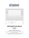
Control Surface Manual
Document Revision: 1.1
Part Number: 840-08758-02
Release Date: September, 2003
Euphonix, Inc.
220 Portage Ave.
Palo Alto, California 94306
Phone:
650-855-0400
Fax:
650-855-0410
Web:
http://www.euphonix.com
e-mail:
[email protected]
In the interest of continued product development, Euphonix reserves the right to make
improvements to this manual and the product it describes at any time, without notice or
obligation.
System 5, S5, PatchNet, eMix, EuCon, R1, Studio Hub, Audio Deck, Max Air, Reel Feel,
Clear Displays, Track Panner, SnapShot Recall, DSC (Digital Studio Controller), HyperSurround, Total Automation and Mix View are trademarks of Euphonix, Inc.
Manual design by Rob Wenig.
Manual written by Tim Driedger, Steve Milne, and Rob Wenig.
©2003 Euphonix, Inc. All rights reserved worldwide. No part of this publication may be
reproduced, transmitted, transcribed, stored in a retrieval system, or translated into any
language in any form by any means without written permission from Euphonix, Inc.
Note:
This equipment has been tested and found to comply with the limits for a
Class A digital device pursuant to Part 15 of the FCC Rules. These limits
are designed to provide reasonable protection against harmful interference
when the equipment is operated in a commercial environment. This equipment generates, uses, and can radiate radio frequency energy and, if not
installed and used in accordance with the instruction manual, may cause
harmful interference to radio communications. Operation of this equipment
in a residential area is likely to cause harmful interference in which case
the user will be required to correct the interference at his own expense.
Caution: Any changes or modifications made by the user that are not expressly approved by Euphonix could void the user’s right to operate the equipment.
IMPORTANT SAFETY INSTRUCTIONS
The lighting flash with arrowhead symbol within an equilateral triangle, is intended to alert
the user to the presence of uninsulated “dangerous voltage” within the product’s enclosure
that may be of sufficient magnitude to constitute a risk of electrical shock to persons.
The exclamation point within an equilateral triangle, is intended to alert the user to the
presence of important operating and maintenance (servicing) instructions in the literature
accompanying the product.
1) Read these instructions.
2) Keep these instructions.
3) Heed all warnings.
4) Follow all instructions.
5) Do not use this apparatus near water.
6) Clean only with a dry cloth.
7) Do not block any ventilation openings. Install in accordance with the manufacturer’s instructions.
8) Do not install near any heat sources such as radiators, heat registers, stoves, or other apparatus
(including amplifiers) that produce heat.
9) Do not defeat the safety purpose of the polarized or grounding-type plug. A polarized plug has
two blades with one wider than the other. A grounding type plug has two blades and a third
grounding prong. The wider blade or the third prong are provided for your safety. If the provided
plug does not fit into your outlet, consult an electrician for replacement of the obsolete outlet.
10) Protect the power cord from being walked on or pinched particularly at plugs, convenience
receptacles, and the point where they exit from the apparatus.
11) Only use attachments/accessories specified by the manufacturer.
12) Use only with the cart, stand, tripod, bracket, or table specified by the manufacturer, or sold
with the apparatus. When a cart is used, use caution when moving the cart/apparatus combination to avoid injury from tip-over.
13) Unplug this apparatus during lightning storms or when unused for long periods of time.
14) Refer all servicing to qualified service personnel. Servicing is required when the apparatus has
been damaged in any way, such as power-supply cord or plug is damaged, liquid has been
spilled or objects have fallen into the apparatus, the apparatus has been exposed to rain or
moisture, does not operate normally, or has been dropped.
15) WARNING – TO REDUCE THE RISK OF FIRE OR ELECTRIC SHOCK, DO NOT EXPOSE
THIS APPARATUS TO RAIN OR MOISTURE.
16) Do not expose this equipment to dripping or splashing and ensure that no objects filled with
liquids, such as vases, are placed on the equipment.
17) To completely disconnect this equipment from the AC Mains, disconnect the power supply
cord plug from the AC receptacle.
18) The mains plug of the power supply cord shall remain readily operable.
19) This unit is provided with a power supply cord set suitable for 120V AC input only (for U.S.A.
and Canada). For other than U.S.A. and Canada, a qualified person must provide for use with
this unit, an appropriate, approved power supply cord set which is in compliance with the end
use country requirements and has a minimum cross-sectional area of 1.0mm2.
20) For units with more than one power cord:
Caution: This unit has more than one power supply cord. Disconnect two power supply
cords before servicing to avoid electrical shock.
Attention: Cet appareil comporte plus d’un cordon d’alimentation. Afin de prévenir les
chocs électriques, débrancher les deux cordons d’alimentation avant de faire le
dépannage.
21) Operator Accessible Fuse:
Caution: For continued protection against risk of fire, replace only with same type and
rating of fuse.
Attention: Pour ne pas compromettre la protection contre les risques d’incendie, remplacer
par un fusible de même type et de même caractéristiques nominales.
Euphonix Max Air Control Surface Manual
Table of Contents
System Startup Sequence ..........................................................................................7
Description ................................................................................................................7
Overview.........................................................................................................7
Self Test Procedure ...................................................................................................9
Initiating Self Test...........................................................................................9
Switch and Knob Test .....................................................................................9
LED Test .......................................................................................................10
Fader Test......................................................................................................10
Display Test ..................................................................................................11
Memory Test .................................................................................................11
Selecting and Adjusting the Onscreen Display .......................................................12
Touchscreen Alignment ..........................................................................................13
Changing the ID of a CM416 Module ....................................................................15
System Ethernet IP Addresses.................................................................................15
Technical Specifications .........................................................................................16
Power ............................................................................................................16
Environmental Requirements........................................................................16
Dimensions....................................................................................................17
User Reference ........................................................................................................19
Internal Components .....................................................................................19
Fans ...............................................................................................................20
v
Euphonix Max Air Control Surface Manual
List of Figures
1
Typical Console Layout ......................................................................................................7
2
CM404 Rear Panel ..............................................................................................................8
3
CM416 Rear Panel ..............................................................................................................8
4
Control surface self-test keys ..............................................................................................9
5
12
6
13
7
13
8
14
9
Changing the CM416 ID ...................................................................................................15
10
Side Dimensions ...............................................................................................................17
11
CM416 Bottom Dimensions .............................................................................................17
12
CM404 Bottom Dimensions .............................................................................................18
13
Max Air Top Dimensions .................................................................................................18
14
CM404 ..............................................................................................................................19
15
CM416 ..............................................................................................................................19
vi
Euphonix Max Air Control Surface Manual
System Startup Sequence
See page 21 in the Max Air Operation Manual for the system startup sequence.
Description
The Max Air Console consists of a configurable number of Control Modules that comprise the Control Surface. The Max Air Control Surface is the digital control center for
all Max Air system components and communicates with them via Ethernet network
connections. Control signals are transmitted via the Ethernet switch and distributed to
the Max Air system components. No audio passes through the Control Surface.
Overview
The Max Air console must contain a CM404 center section module and can have up to
three fully loaded CM416 16-channel Modules, each with 16 physical faders. The system
can have up to 48 faders, not including the eight faders in the CM404 master section.
The CM416HL and CM416HR are half-loaded (left or right) 8-fader modules that can
be used to expand your system.
CM416
Sixteen-channel Module
CM404
Center Section
CM416
Sixteen-channel Module
Figure 1 Typical Console Layout
7
Euphonix Max Air Control Surface Manual
Rear Panels
INTERNAL
EXTERNAL
TALKBACK MIC TALKBACK MIC
SERVICE
AC IN 1
SERIAL 1
T 5.0 AH
250 V
I
I
O
~100-240V
AC
50-60 Hz
250 Watts
O
Caution:
To prevent risk
of fire, replace
fuse with the
same type and
rating.
SERIAL 2
TO KVM
EXTENDER
AC IN 2
MOUSE
LAN
CM404
KEYBOARD
Figure 2 CM404 Rear Panel
~100-240V
AC
50-60 Hz
250 Watts
I
Caution:
To prevent risk
of fire, replace
fuse with the
same type and
rating.
~100-240V
AC
50-60 Hz
250 Watts
O
Caution:
To prevent risk
of fire, replace
fuse with the
same type and
rating.
I
AC IN 2
T 5.0 AH
250 V
O
AC IN 1
T 5.0 AH
250 V
LAN
SERVICE
SERIAL 1
SERIAL 2
CM416
Figure 3 CM416 Rear Panel
Power Connectors (IEC): Accepts two standard IEC power cords (provided). Two autoranging switching supplies accept voltages between 100–240 VAC, 50–60 Hz.
LAN Port (RJ45): Connect to EuCon Network Hub via RJ45 through the console
ethernet harness (provided).
To KVM Extender (RJ45): Connection to KVM extender (CM404 only)
Talkback (XLR): Connection to the internal and external talkback microphones.
Keyboard and Mouse (PS2): Connection to the keyboard and mouse or trackball.
Serial 1, 2 (DB9): RS232 serial ports (for service only).
Service (DB15HD, PS2): VGA video and keyboard connection (for service only).
8
Euphonix Max Air Control Surface Manual
Self Test Procedure
The following pages describe the operation of standalone self-test software for the Max
Air control modules. The self-test code is designed to be invoked in a module right after
power-up and before the Single Board Computer (SBC) downloads code.
Initiating Self Test
Enter self-test by pressing the self-test enter keys shown below. This must be done before the SBC code download. If code download from the SBC occurs during the selftest, the module automatically exits self-test and executes the downloaded code. Use
the keys shown below to perform the different tests. After entering the test, use the detailed description of each test on the following pages to navigate through different
modes within a test.
PUSH
Group
Group
Group
Group
1 2 3 4 5 6 7 8
1 2 3 4 5 6 7 8
1 2 3 4 5 6 7 8
1 2 3 4 5 6 7 8
9 10 11 12 13 14 15 16 9 10 11 12 13 14 15 16 9 10 11 12 13 14 15 16 9 10 11 12 13 14 15 16
17 18 19 20 21 22 23 24 17 18 19 20 21 22 23 24 17 18 19 20 21 22 23 24 17 18 19 20 21 22 23 24
25 26 27 28 29 30 31 32 25 26 27 28 29 30 31 32 25 26 27 28 29 30 31 32 25 26 27 28 29 30 31 32
Group
Group
Group
Group
1 2 3 4 5 6 7 8
1 2 3 4 5 6 7 8
1 2 3 4 5 6 7 8
1 2 3 4 5 6 7 8
9 10 11 12 13 14 15 16 9 10 11 12 13 14 15 16 9 10 11 12 13 14 15 16 9 10 11 12 13 14 15 16
17 18 19 20 21 22 23 24 17 18 19 20 21 22 23 24 17 18 19 20 21 22 23 24 17 18 19 20 21 22 23 24
25 26 27 28 29 30 31 32 25 26 27 28 29 30 31 32 25 26 27 28 29 30 31 32 25 26 27 28 29 30 31 32
33 34 35 36 37 38 39 40 33 34 35 36 37 38 39 40 33 34 35 36 37 38 39 40 33 34 35 36 37 38 39 40
33 34 35 36 37 38 39 40 33 34 35 36 37 38 39 40 33 34 35 36 37 38 39 40 33 34 35 36 37 38 39 40
41 42 43 44 45 46 47 48 41 42 43 44 45 46 47 48 41 42 43 44 45 46 47 48 41 42 43 44 45 46 47 48
41 42 43 44 45 46 47 48 41 42 43 44 45 46 47 48 41 42 43 44 45 46 47 48 41 42 43 44 45 46 47 48
Aux
Aux
1 2 3 4 5 6 7 8
Aux
1 2 3 4 5 6 7 8
Aux
1 2 3 4 5 6 7 8
Aux
1 2 3 4 5 6 7 8
Aux
1 2 3 4 5 6 7 8
Aux
1 2 3 4 5 6 7 8
1 2 3 4 5 6 7 8
1 2 3 4 5 6 7 8
9 10 11 12 13 14 15 16 9 10 11 12 13 14 15 16 9 10 11 12 13 14 15 16 9 10 11 12 13 14 15 16
9 10 11 12 13 14 15 16 9 10 11 12 13 14 15 16 9 10 11 12 13 14 15 16 9 10 11 12 13 14 15 16
17 18 19 20 21 22 23 24 17 18 19 20 21 22 23 24 17 18 19 20 21 22 23 24 17 18 19 20 21 22 23 24
17 18 19 20 21 22 23 24 17 18 19 20 21 22 23 24 17 18 19 20 21 22 23 24 17 18 19 20 21 22 23 24
Mix
Mix
A B C D E F G H
Knobset
Select
Expand
In Out
Mix
A B C D E F G H
Mix
A B C D E F G H
Mix
A B C D E F G H
Mix
A B C D E F G H
Mix
A B C D E F G H
Mix
A B C D E F G H
A B C D E F G H
*
*
*
*
*
*
*
*
Ins Inp
Ins Inp
Ins Inp
Ins Inp
Ins Inp
Ins Inp
Ins Inp
Ins Inp
Dyn
Dyn
Dyn
Dyn
Dyn
Dyn
Dyn
Dyn
EQ
EQ
EQ
EQ
EQ
EQ
EQ
EQ
Filt
Filt
Filt
Filt
Filt
Filt
Talkback Mic
Aux
Filt
Filt
Aux
Pan
Aux
Pan
Aux
Pan
Aux
Pan
Aux
Pan
Aux
Pan
Aux
Pan
Aux
Pan
Mix
Group
Mix
Group
Mix
Group
Mix
Group
Mix
Group
Mix
Group
Mix
Group
Mix
Group
Mix-
Bus
Mix-
Bus
Mix-
Bus
Mix-
Bus
Mix-
Bus
Mix-
Bus
Mix-
Bus
Mix-
Bus
Switch #
Switch #
Oscillator
Enter Self Test
Monitors
XXXX
Select
Select
Select
Select
Select
Select
Select
On
XXXX
Select
Switch Value
Setup
Switch Value
RWG
Solo
XXXX
On
On
On
On
On
On
On
On
Select
Select
Select
Select
Select
Select
Select
Select
XXXX
Control Room
Dim
Setup
Cut
Main
Spkrs
Level
Alt 1
Spkrs
Clear
Solo
Alt 2
Spkrs
On
On
On
On
On
On
On
On
Select
Select
Select
Select
Select
Select
Select
Select
RWG
Setup
Setup
Enter Self Test
Dyn
Comp
Exp / Gate
On
On
On
On
On
On
On
On
Select
Select
Select
Select
Select
Select
Select
Select
On
On
Copy
Talk
Paste
Swap
On
Copy
Talk
Swap Channel
Main Channel
Paste
Main Channel
On
Select
Aux
Masters
Aux
Sends
Group Bus
Masters
*
Copy
Mix
Masters
Chan
Select
Faders
Chan
Select
Setup
On
Solo
On
Select
Custom
M S L
Select
Threshold
Ratio
Gain
Dyn
Select
On
Select
M S L
Select
Lo Mid Q
Hi Mid Q
Low Freq
Lo Mid Freq
Hi Mid Freq
High Q
Knob Value
Setup
Talk To
All
Custom
Talk To
Mon A
Talk To
Mon B
Band
In
M S L
Select
Knob #
Shelf
Low Q
High Freq
Talkback / Slate
Solo
On
Select
M S L
Select
Chan
Select
Solo
On
Select
M S L
Select
Chan
Select
Solo
On
Select
M S L
Select
Chan
Select
Solo
On
Select
M S L
Select
Function
Select
XXXX XXXX
Version
Chan
Select
Solo
On
Select
M S L
Select
Memory
Chan
Select
Solo
On
Select
M S L
AA
Select
Displays
Chan
Select
Solo
Select
M S L
Select
LEDs
Workstation
Solo
On
Select
M S L
Select
Shelf
To
Faders
Link
Main Channel
Chan
Select
Solo
On
Select
M S L
Select
Knob Value
All
Clear
XXXX XXXX
Chan
Select
Solo
Depth
EQ
Soft Knobs
Paste
Swap
Swap Channel
In
Dyn In
Knob #
Copy
Talk
Swap
Swap Channel
Release
Soft
Knobs
On
Copy
Talk
Main Channel
Chan
Select
Solo
M S L
Select
Paste
Swap
Swap Channel
Version
On
Select
On
Copy
Talk
Main Channel
Chan
Select
Solo
M S L
Select
Paste
Swap
Swap Channel
Main Channel
On
Select
On
Copy
Talk
Memory
Chan
Select
Solo
M S L
Select
Paste
Swap
Swap Channel
Main Channel
On
Select
M S L
On
Copy
Talk
Displays
Chan
Select
Solo
On
Select
Paste
Swap
Swap Channel
Faders
Chan
Select
Solo
On
Copy
Talk
Main Channel
LEDs
Chan
Select
Select
Paste
Swap
Swap Channel
Attack
Band
In
Low Gain
Band
In
Lo Mid Gain
Insert
Knobsets
Custom
Pan
Filters
Band
In
Hi Mid Gain
EQ
In
In
Setup
Snapshots
Layouts
EQ
Select
LPF HPF BPF NCH
Type
High Gain
Soft
Knobs
LPF HPF BPF NCH
Type
Filters
Select
BB
12
48V
Lock ST
6
Mix-
12
48V
Lock ST
6
Mix-
12
48V
Lock ST
6
Mix-
12
48V
Lock ST
6
Mix-
12
48V
Lock ST
6
Mix-
12
48V
Lock ST
6
Mix-
12
48V
Lock ST
6
Mix-
12
48V
12
48V
CC
Lock ST
6
Mix-
Lock ST
6
Mix-
12
48V
Lock ST
6
Mix-
12
48V
Lock ST
6
Mix-
12
48V
Lock ST
6
Mix-
12
48V
Lock ST
6
Mix-
12
48V
Lock ST
6
Mix-
12
48V
Lock ST
6
Mix-
12
48V
Lock ST
6
Mix-
7
8
9
Soft
Knobs
In
0
0
6
Enter Other Tests
6
12
clip
18
0
6
18
0
3
6
48
12
72
24
24
30
36
42
48
60
72
18
0
3
6
48
12
72
24
24
30
36
42
48
60
72
18
0
3
6
48
12
72
24
24
30
36
42
48
60
72
18
0
3
6
48
12
72
24
24
30
36
42
48
60
72
18
0
3
6
48
12
72
24
24
30
36
42
48
60
72
18
0
3
6
48
12
72
24
24
30
36
42
48
60
72
12
clip
18
0
6
12
3
24
6
48
12
72
24
24
30
36
42
48
60
72
0
DD
12
3
24
6
48
12
72
24
0
6
6
12
clip
6
12
24
0
6
12
clip
6
12
24
0
6
12
clip
6
12
24
0
6
12
clip
6
12
24
0
6
12
clip
6
12
24
0
6
12
clip
6
12
24
0
Enter Other Tests
6
0
6
0
6
0
6
0
6
0
6
4
5
6
1
2
3
In
12
clip
FF
18
0
6
GG
30
HH
12
clip
18
0
6
12
3
24
6
48
12
72
24
24
30
36
42
48
60
72
12
clip
18
0
6
12
3
24
6
48
12
72
24
24
30
36
42
48
60
72
12
clip
18
0
6
12
3
24
6
48
12
72
24
24
30
36
42
48
60
72
12
clip
18
0
6
12
3
24
6
48
12
72
24
24
30
36
42
48
60
72
12
clip
18
0
6
12
3
24
6
48
12
72
24
24
30
36
42
48
60
72
18
0
6
12
3
24
6
48
12
72
24
24
30
36
42
48
60
72
12
clip
RTM
18
0
In
6
12
3
24
6
48
12
72
24
24
30
36
42
48
60
72
12
3
24
6
48
12
72
24
24
Clear
0
Enter
30
36
42
48
60
72
One Shot
Setup
In
Filter 2
Input A
Input B
Input
6
12
clip
Filter 1
LTM
EE
24
36
42
48
60
72
0
In
Surround
Front Pan
Balance
Pan
Select
Selected
Channel
Soft
Knobs
A On
Hi Z
B On
48 V
Input
Select
HPF
Soft
Knobs
Mic Gain
Trim
Setup
Figure 4 Control surface self-test keys
Switch and Knob Test
Momentary Switch Press
Pressing any switch toggles the switch value display from 00 to 01 and shows the
switch number in the display.
Knob Value Display
Turning any knob displays the hex value (00–60) of the knob and shows the knob number in the display.
9
Euphonix Max Air Control Surface Manual
LED Test
LED loop
This switch cycles through all the LED colors.
Color Toggle
These switches light all the LEDs of each color: green, red, yellow, orange
All LEDS
This turns all LEDs on.
NOTE: To avoid overheating, the module should not be left with All LEDS on for more
than 5 minutes.
Fader Test
All Fader Up
All faders all the way up.
All Fader Down
All faders all the way down.
Fader Echo Test
All faders follow the one fader touched.
Fader Loop Test with Speed Control
All faders cycle up and down at the speed determined by the speed control knob. This
fader cycle test times out after 5 minutes to protect the faders from burning out.
Backstop PFL Switch Test
The Backstop PFL display lights up when a fader is pulled back to enable its backstop
PFL switch. This mode is always active.
Fader I/O
•
Fader Write value display
Any value written to a fader is displayed in its designated fader write intelligent
display. This mode is always active in fader test mode.
•
Fader Read value display
All faders are continuously read and the read value is displayed in its designated fader read intelligent display.
10
Euphonix Max Air Control Surface Manual
Display Test
Clear All
Char Up
Char Down
Char E
Char W
Enumerate
Memory Test
ROM Test
This test reads the ROM and computes and displays the checksum. The user/tester can
match the checksum to a known good checksum (see below) to make sure ROM test is
successful.
CM404 Checksum - 6514
CM416 Checksum - D308
RAM Test
This tests the upper unused portion of the CPU board RAM. The Pass display shows
up when the test is done.
PC104 RAM Test
This test writes and reads the whole PC104 RAM and checks for errors. The Pass display shows up when the test is done.
11
Euphonix Max Air Control Surface Manual
Selecting and Adjusting the Onscreen Display
The Touchscreen image controls are found on the panel behind the Touchscreen. If
the image needs adjustment, access press the Menu button and follow the onscreen
instructions.
Figure 5
12
Euphonix Max Air Control Surface Manual
Touchscreen Alignment
The Max Air Touchscreen can be calibrated using the Elo Touchscreen utility. Note
that different users may have slightly different ways of touching the screen. If an operator finds they often miss onscreen objects, re-calibrate the touchscreen:
1.
Select Control Panel from the Start menu.
Figure 6
2.
Double-touch Elo Touchscreen.
Figure 7
The Elo popup appears.
13
Euphonix Max Air Control Surface Manual
Figure 8
3.
Touch Align and follow the onscreen instructions.
When asked to touch the targets on the screen, best results are achieved by touching the
targets naturally without thinking too much about it. This aligns the touchscreen to an
individual’s hand-eye coordination.
14
Euphonix Max Air Control Surface Manual
Changing the ID of a CM416 Module
1.
Power cycle the module and then simultaneously press and hold the two lower
knobs on the first strip before the module connects to the System PC (you have
about 15 seconds).
Change ID
Select
Select
Select
Select
Select
Select
Select
Select
On
On
On
On
On
On
On
On
Select
Select
Select
Select
Select
Select
Select
Select
On
On
On
On
On
On
On
On
Select
Select
Select
Select
Select
Select
Select
Select
On
On
On
On
On
On
On
On
Select
Select
Select
Select
Select
Select
Select
Select
On
On
Copy
Paste
On
Copy
Paste
On
Copy
Paste
On
Copy
Paste
On
Copy
Paste
On
Copy
Paste
On
Copy
Paste
Copy
Paste
Figure 9 Changing the CM416 ID
2.
Set the ID using the first strip only in each CM416. Do not set the ID using strip
nine.
The CM416 displays shows “Position – 0000 Use 1st fader to set module position.”
3.
Move the fader on strip one to select the ID.
The ID appears as a hexadecimal number (0=ID 1, 1=ID 2, 2=ID 3, 3=ID 4,
4=ID 5, 5=ID 6).
4.
Press strip one’s fader Select key to commit to the new ID.
The module continues to boot only after committing to the change.
System Ethernet IP Addresses
System Computer
Interface Pilot
Digital Pilot
CM404
CM416
Strip 1
Strip 9
Strip 17
Strip 25
Strip 33
Strip 41
192.168.0.1
192.168.0.208
192.168.0.200
192.168.0.19
192.168.0.10
192.168.0.11
192.168.0.12
192.168.0.13
192.168.0.14
192.168.0.15
ID 9
ID 1
ID 10
ID 1
ID 2
ID 3
ID 4
ID 5
ID 6
15
Euphonix Max Air Control Surface Manual
Technical Specifications
Power
Voltage
Power Consumption
Inrush Current
Fuse
Heat Dissipation
90–254 VAC (RMS), 50/60 Hz
2 x 50 W per module
1.0 A (US 117 V)
0.5 A (Europe 230 V)
1.0 A (Japan 100 V)
25 A
T5 A
CM404
520 BTU/hr
CM416
600 BTU/hr
CM416H 520 BTU/hr
Environmental Requirements
Operating Temperature
Storage Temperature
Humidity
0–35°C (Ambient)
-10 to 55°C
0–90% non-condensing
16
Euphonix Max Air Control Surface Manual
75.00°
16.25
CM416 BALANCE POINT
CM404 BALANCE POINT
Dimensions
Dimensions in inches
16.13
15.625
8.39
6.78
3.06
2.06
1.20
5.85
4.39
0
9.83
11.42
20.83
22.42
28.50
29.58
0
Figure 10 Side Dimensions
0
.900
0
.902
KEEP CLEAR FOR
VENTILATION
11.723
12.827
KEEP CLEAR FOR
VENTILATION
1/4-20 THREADED
INSERT 8 PLACES
23.400
24.300
Figure 11 CM416 Bottom Dimensions
17
.53
0
8.742
9.83
11.42
20.83
22.42
23.648
24.300
Euphonix Max Air Control Surface Manual
0
.90
1.79
KEEP CLEAR
FOR PROPER
VENTILATION
1/4-20 THREADED
INSERT 8 PLACES
19.46
.53
0
8.742
9.83
11.42
20.83
22.42
21.40
22.30
Figure 12 CM404 Bottom Dimensions
35.43
29.58
0.00
0.00
5.85
Figure 13 Max Air Top Dimensions
18
24.30
0.00
22.30
16.15
0.00
1.0
1.0
Euphonix Max Air Control Surface Manual
User Reference
Internal Components
Power
Distribution
Dual Power
Connections
Dual Power
Supplies
Single Board
Computer
KVM Extender
Figure 14 CM404
Dual Power
Connections
Dual Power
Supplies
Power
Distribution
Single Board
Computer
Figure 15 CM416
19
Euphonix Max Air Control Surface Manual
Fans
The CM416 modules have low-noise internal fans and a thermal sensor between the
displays on strips five and six. If a module gets too hot, the fans automatically turn on
at a low or high speed depending on the temperature. The fans turn off automatically
when the internal temperature returns to normal.
20