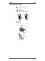
1
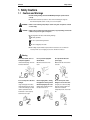
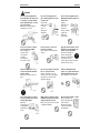
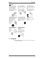
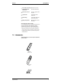
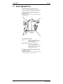
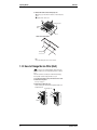
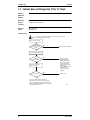
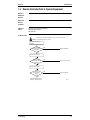
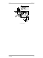
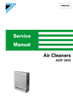
SiE74-202
Service
Manual
Air Cleaners
MC401VE
MC401
SiE74-202
Air Cleaners
1. Safety Cautions...................................................................................... iii
1.1 Cautions and Warnings ........................................................................... iii
1.2 Using Icons.............................................................................................. v
1.3 Using Icons List .......................................................................................vi
Part 1 Operation Manual ..............................................................1
1. Operating Manual....................................................................................2
1.1
1.2
1.3
1.4
1.5
1.6
1.7
1.8
1.9
1.10
1.11
1.12
1.13
1.14
1.15
1.16
Names and Functions of Parts ................................................................ 4
Indicator Lamps and their Functions ....................................................... 4
Accessories ............................................................................................. 5
Tips for appropriate use........................................................................... 6
CAUTION ................................................................................................ 7
Names and Functions of The Operating Section..................................... 8
Names and Functions of The Indicator Lamps........................................ 9
Setup ..................................................................................................... 10
Installation ............................................................................................. 11
How to Operate the Unit ........................................................................ 12
How to Clean the Prefilter...................................................................... 13
How to Clean the Front Panel ............................................................... 13
How to Clean the lonizer ....................................................................... 14
How to Change the Ion Filter (Roll) ....................................................... 16
Optional Accessories............................................................................. 17
Specifications ........................................................................................ 17
Part 2 Troubleshooting ..............................................................19
1. Troubleshooting ....................................................................................20
1.1
1.2
1.3
1.4
Equipment does not Operate................................................................. 20
Indicator does not Change from "Dirty" to "Clean" ................................ 22
Remote Controller Fails to Operate Equipment..................................... 23
Photocatalytic Operation does not Activate........................................... 24
Part 3 Removal Procedure .........................................................27
1. Removal Procedure of MC401VE .........................................................28
1.1
1.2
1.3
1.4
1.5
1.6
Removal of External Accessories.......................................................... 28
Removal of Ionizing Wire....................................................................... 30
Removal of Electrical Parts (Inverter Lamp).......................................... 31
Removal of PCB .................................................................................... 34
Removal of Fan Motor ........................................................................... 36
Removal of Safety Switch...................................................................... 37
Part 4 Reference Data ...............................................................39
1. Wiring Diagram .....................................................................................40
1.1 MC401VE .............................................................................................. 40
2. Parts List ...............................................................................................41
Table of Contents
i
SiE74-202
2.1 Parts Illustration..................................................................................... 41
2.2 Parts List................................................................................................ 42
Index
............................................................................................ i
Drawings & Flow Charts ..............................................................iii
ii
Table of Contents
SiE74-202
Safety Cautions
1. Safety Cautions
1.1
Cautions and Warnings
Read the following warnings and cautions BEFORE operating the system and use it
correctly.
This manual classifies the precautions to the user into the following two categories.
Each mention important cautions on safety, so be sure to keep them.
WARNING
Failure to follow a warning is very likely to result in such grave consequences as death
or serious injury.
CAUTION
Failure to follow a caution may result in serious injury or property damage, and in certain
conditions, may result in a grave consequence.
The pictograms in the text show the following meanings.
Absolutely prohibited
Be sure to operate following instructions
Be sure to unplug the power cable
After reading, keep this manual in a place where the actual user can see it whenever
necessary. And in case of changing user, be sure to hand it to the new user.
Warning
Do not disassemble, service or
modify this equipment.
Unwarranted tempering can lead to
fire and/or malfunction.
Do not operate the equipment
with wet hands.
Otherwise electrical shock can
result.
Use only 220-240 VAC 50 Hz
power supply.
Otherwise fire and electrical shock
can result.
Do not use the power cable if it is
damaged.
Using a damaged power cable is
extremely hazardous; if the power
cord becomes damaged, you must
obtain a replacement from the
manufacturer or from a properlyauthorized service agent.
Before changing filters, cleaning
the equipment or moving it, turn it
OFF and unplug the power cable.
Working with power ON can lead to
fire and/or electric shock.
Do not use the power cable if
damaged or loose in the socket.
Using the power cable in anything
but proper working condition can
lead to short-circuits and
subsequently electric shock and/or
fire.
iii
Safety Cautions
SiE74-202
Caution
Do not use the equipment in a
place filled with oily smoke such
as a kitchen or in a place filled
with combustible gas, corrosive
gas or metal dust.
Otherwise fire and equipment
malfunction can result.
Do not use in humid places or
places which might be wet, such
as bathrooms.
Contact with
water can lead
to electric
shock or
damage the
equipment.
Do not use the equipment near a
lighting fixture (keep a distance of
at least 1 m).
Lighting
equipment can
cause poor
reception of
remote controller
signals and
equipment
discoloration.
Do not use outdoors or where
exposed to direct sunlight.
Direct sunlight can
weaken remote
control signal
reception
sensitivity and
discolor the casing.
Do not use near to sources of
heat such as heaters.
Heat can discolor and deform the
casing.
Keep the unit and remote control
minimum 1 m from lighting, TVs,
radios, stereos and aerials.
This unit can disturb TV
pictures and generate
interference. Illumination
can weaken remote
control signal reception sensitivity
and discolor the casing.
Keep the equipment 10 cm or
more away from the wall when
used on a table.
Otherwise the wall can become
dirty.
Do not use in the place of kitchen
fans or cooker hood fans.
Adverse conditions of use can
shorten service-life of the prefilter
and ion filter, as well as lead to
equipment damage.
Prevent combustibles (hair
sprays, etc.), sparks and incense
from being drawn into the unit.
Such substances can cause fire.
Do not insert fingers or objects
into the openings of the suction
and discharge grilles.
Otherwise
electrical shock
and equipment
malfunction can
result.
When used in conjunction with a
humidifier, keep mist from being
directly drawn into the unit.
Mists can lead to electric shock and/
or equipment damage.
Do not block the intake or outlet.
Blocked openings can
reduce capacity (air will
not be cleaned
throughout the entire
room) and/or damage
the equipment.
iv
SiE74-202
Safety Cautions
Caution
Do not place water containers
such as fish bowls and flower
vases near the equipment.
Water can cause electrical shock
and equipment malfunction when it
enters the equipment.
Do not wipe with benzene or
thinner, or spray with insecticide.
Such
substances can
cause cracking,
electric shock
and/or fire.
If not using the unit for long
periods of time, unplug the power
cable.
Dielectric breakdown can lead to
leakage current and subsequently
electric shock and/or fire.
Hold the plug to unplug the power
cord from the AC outlet. Do not
pull the cord to unplug.
Otherwise electrical
shock can result or
sparks may be
generated due to
shorting.
Do not operate the equipment
without the prefilter or roll filter.
Operating the equipment without the
filter can result in equipment
malfunction.
Do not sit or stand on the
equipment.
Otherwise equipment malfunction
can result.
Do not position the equipment on
its side or tilt it during use.
Otherwise
equipment
malfunction can
result.
Ventilate the room frequently
when used together with a
heating device.
This product does not remove
carbon monoxide. Insufficient
ventilation can result in carbon
monoxide poisoning.
1.2
Using Icons
Icons are used to attract the attention of the reader to specific information. The meaning of each
icon is described in the table below:
v
Safety Cautions
1.3
SiE74-202
Using Icons List
Icon
Type of
Information
Note
Description
A “note” provides information that is not indispensable, but may
nevertheless be valuable to the reader, such as tips and tricks.
Note:
Caution
A “caution” is used when there is danger that the reader, through
incorrect manipulation, may damage equipment, loose data, get
an unexpected result or has to restart (part of) a procedure.
Warning
A “warning” is used when there is danger of personal injury.
Reference
A “reference” guides the reader to other places in this binder or
in this manual, where he/she will find additional information on a
specific topic.
Caution
Warning
vi
SiE74-202
Part 1
Operation Manual
1. Operating Manual....................................................................................2
1.1
1.2
1.3
1.4
1.5
1.6
1.7
1.8
1.9
1.10
1.11
1.12
1.13
1.14
1.15
1.16
Operation Manual
Names and Functions of Parts ................................................................ 4
Indicator Lamps and their Functions ....................................................... 4
Accessories ............................................................................................. 5
Tips for appropriate use........................................................................... 6
CAUTION ................................................................................................ 7
Names and Functions of The Operating Section..................................... 8
Names and Functions of The Indicator Lamps........................................ 9
Setup ..................................................................................................... 10
Installation ............................................................................................. 11
How to Operate the Unit ........................................................................ 12
How to Clean the Prefilter...................................................................... 13
How to Clean the Front Panel ............................................................... 13
How to Clean the lonizer ....................................................................... 14
How to Change the Ion Filter (Roll) ....................................................... 16
Optional Accessories............................................................................. 17
Specifications ........................................................................................ 17
1
Operating Manual
SiE74-202
1. Operating Manual
OPERATING MANUAL
MODEL
MC401VE
MC40
2
1VE
1
2
4
PHOTOCA
TALYTIC
Operation Manual
SiE74-202
Operating Manual
Thank you for purchasing this Daikin Air Cleaner.
This instruction manual explains how to use the equipment and important safety precautions.
READ IT CAREFULLY BEFORE using the equipment.
Keep this manual handy for future reference.
Your warranty is included in the product package. Check your warranty has been properly filled
out by the place of purchase and keep it in a handy but safe place.
Operation Manual
3
Operating Manual
1.1
Names and Functions of Parts
1.2
Indicator Lamps and their Functions
4
SiE74-202
Operation Manual
SiE74-202
Operating Manual
1 Photocatalytic deodorizing, Eliminates odors 3 times
bacteria removal and
faster than earlier models.
antiviral effect
2 Plasma dust collection
Clears air of cigarette smoke
and pollen.
3 7-year filter roll
Longer-lasting and less
troublesome.
4 Silent running
Just 34.5 dB in “High” mode.
16 dB in “Silent” mode.
5 Energy-saving inverter
Great especially if you use it
all day-long.
Inverter lamp (Photocatalytic cleaning).
The inverter lamp illuminates a photocatalyst which inactivates bacteria
and viruses by high oxidation, thus minimizing the possibility of
contamination. It also decomposes components which generate
offensive odor in cigarette smoke, raw waste, exhaust gas (NOx), etc.
∗ When used for the first time, the smell of the photocatalyst can be
detected coming from the air outlet, but there is nothing wrong with
the equipment. As the unit runs, the odor will be decomposed and
eventually eliminated.
1.3
Accessories
Check the following accessories have been included in the
product package.
Filter roll
(7 filters per roll)
PH
O
AI TOC
R
C L TA I
EA YT
NE IC
R
AR C1
7A 53
Wireless remote
control
Batteries (AA × 2)
Operation Manual
5
Operating Manual
1.4
SiE74-202
Tips for appropriate use
To remove house dust, set the unit near to the floor.
To remove cigarette smoke, install the unit high on a wall.
Installing the air cleaner as shown below improves air
circulation in the room.
While heating or cooling the room, air can be cleaned and temperature
fluctuation minimized.
Set operating mode as needed.
Auto ............................. Fan speed is controlled automatically
depending on air quality. This mode ensures
the most efficient operation.
Manual (Fan speed) ... Manual (Fan speed) - The unit runs
independent of air quality. This mode is
effective for regularly removing orders not
readily detected by the odor sensor or quickly
eliminating house dust in room air.
Use the OFF timer appropriately to ensure the best room
air quality when needed.
If the OFF timer is set when leaving the room, the air is clean when you
return. When cleaning the room, set fan speed to “High”.
6
Operation Manual
SiE74-202
1.5
Operating Manual
CAUTION
Read this section carefully BEFORE using the
equipment.
Do not use the power cable if it is damaged.
Using a damaged power cable is extremely hazardous; if the
power cord becomes damaged, you must obtain a replacement
from the manufacturer or from a properly-authorized service
agent.
Do not use in humid places or places which might
be wet, such as bathrooms.
Contact with water can lead to electric shock or damage the
equipment.
Do not use outdoors or where exposed to direct
sunlight.
Direct sunlight can weaken remote control signal reception
sensitivity and discolor the casing.
Before changing filters, cleaning the equipment or
moving it, turn it OFF and unplug the power cable.
Working with power ON can lead to fire and/or electric shock.
Do not disassemble, service or modify this equipment.
Unwarranted tampering can lead to fire and/or malfunction.
Do not wipe with benzene or thinner, or spray with
insecticide.
Such substances can cause cracking, electric shock and/or fire.
Do not block the intake or outlet.
Blocked openings can reduce capacity (air will not be
cleaned throughout the entire room) and/or damage the
equipment.
Do not use near to sources of heat such as heaters.
Heat can discolor and deform the casing.
Do not use the power cable if damaged or loose in
the socket.
Using the power cable in anything but proper working
condition can lead to short-circuits and subsequently electric
shock and/or fire.
Keep the unit and remote control minimum 2 m
from lighting, TVs, radios, stereos and aerials.
This unit can disturb TV pictures and generate interference.
Illumination can weaken remote control signal reception
sensitivity and discolor the casing.
Operation Manual
7
Operating Manual
SiE74-202
When used in conjunction with a humidifier, keep
mist from being directly drawn into the unit.
Mists can lead to electric shock and/or equipment damage.
Do not use in the place of kitchen fans or cooker
hood fans.
Adverse conditions of use can shorten service-life of the
prefilter and ion filter, as well as lead to equipment damage.
Prevent combustibles (hair sprays, etc.), sparks
and incense from being drawn into the unit.
Such substances can cause fire.
If not using the unit for long periods of time,
unplug the power cable.
Dielectric breakdown can lead to leakage current and
subsequently electric shock and/or fire.
∗ Keep this manual in a handy place so that anyone operating the
equipment can refer to it quickly and easily. Ensure that anyone
unfamiliar with the equipment reads this manual before handling the
equipment.
1.6
Names and Functions of The Operating Section
A Front panel
B Ion filter (roll) case
Positively (+) charges minute dust particles not trapped by the
prefilter.
C Ion filter roll
Working on the principle of electrostatic attraction, the negatively (−)
charged filter catches and removes the positively (+) charged dust.
D Air outlet
E Handle (on rear)
F Inverter lamp
Activates the photocatalyst by illuminating it with light.
G Photocatalyst
Removes odors, bacteria and viruses when activated by the
inverter lamp.
∗ Do not subject the photocatalyst to excessive force. The inverter
lamp located behind it will break.
H Indicator lamps
Display operating status. See page 9.
J Prefilter
Removes comparatively large dust particles.
8
Operation Manual
SiE74-202
1.7
Operating Manual
Names and Functions of The Indicator Lamps
A “Ionizer needs cleaning” lamp
Flashes when the ionizer is dirty. See page 14.
B Time to cut filter lamp/Reset button
This lamp lights up when it is time to change the ion filter. After
with ball-point pen, etc. See page 16.
fitting a new filter, press
C Timer settings
The selected OFF timer setting is lit. As time elapses, the remaining
time is displayed on the remote control. See page 12.
D Auto power save lamp
The lamp lights up in the auto mode once air is clean. This mode is
designed to cut electricity bills. See page 12.
E Pollen/Turbo mode lamps
The corresponding lamp is lit when the unit is in either the pollen or
Turbo mode. See pages 12.
F Inverter lamp
Lit while the inverter lamp is ON. The lamp can be turned OFF from
on the remote control. See page 12.
G Air Quality lamps
These lamps indicate how clean/dirty room air is.
Low odor
Green
intensity
Green
Yellow
High odor
intensity
Green
Yellow
Orange
Green
Yellow
Orange
Red
• Sharp fluctuations in temperature, humidity or odorless gases
(carbon monoxide) can cause lamps to light up and go out.
• In the following cases, the lowest odor intensity is indicated for 1
minute regardless of the true intensity. There is nothing wrong
with the equipment.
• Immediately after reattaching the front panel.
• Immediately after plugging in the power cable.
H Signal reception window
Signals from the remote controller are received through this window.
J Fan speed lamp
The lamp under the set fan speed is lit. See page 12.
K Auto mode lamp
Lit when the unit is in the auto mode. See page 12.
L Mode selector (OFF) button
Every time the button is pressed, the mode switches as follows.
Operation Manual
9
Operating Manual
1.8
SiE74-202
Setup
How to Fit the Ion Filter Roll.
CAUTION
Always fit the prefilter and ion filter roll before use.
Use without filters can damage the equipment.
1. Remove the front panel.
Hold the front panel by the sides, pull up and out.
Front panel
or
Front panel
MC40
1VE
1
2
PHOTOCTAIYTIC
P HO
MC4
AIR
4
01
CLEANER
1
VE
TO
AIR CLEANER
CTAIYTI
C
2
4
2. Remove the ion filter (roll) case.
Hold the ion filter (roll) case by the left and right side handles, and
lift upward and out.
Ion filter (roll) case
Handles
MC40
1VE
MC40
1
1VE
PHOTOCTAIYTIC
1
2
PHOTOCTAIYTIC
AIR
2
AIR
4
CLEANER
CLEANER
4
3. Fit the filter roll.
Q
Face the ion filter (roll) case downwards as shown below and fit
the filter roll in the cutouts for the filter spool.
Filter roll
Holes
Dark side
Cutouts for
filter spool
Ion filter
(roll) case
R
Insert ends
into cutouts.
Fit the holes on leading edge over the pegs on both sides of the
case.
Pegs
Pegs
10
Operation Manual
SiE74-202
1.9
Operating Manual
Installation
Selecting an Installation Site.
The unit can be place on a flat surface such as a desk.
<To place on a desk>
Min. 100 cm
Min. 10cm
MC4
01
1
VE
P HOTOCTAIYTIC
AIR CLEANER
2
4
Min. 10cm
Select a wall, shelf or floor that is sturdy enough to support the unit.
The unit weighs 6.9 kg.
Select a location that blows air across the entire room.
For installation tips, see “Tips for appropriate use” page 6.
How to Mount on Walls
1. Fit the power cable snugly in the cable rest. Also, bundle
up any excess cable with a tie band.
Tie band
2. To prevent falling in the event of an earthquake, the unit
can be rigged with a safety wire as shown below.
Wire
Operation Manual
11
Operating Manual
SiE74-202
1.10 How to Operate the Unit
Before attempting to use the unit, plug the power cable into a single phase 220 – 240 V/220 V (50/60 Hz) socket.
Note
For the first 2 seconds after the front panel has been reattached or the power cable plugged in, the unit does not respond to remote controller
commands - not even the buttons in .
The buttons and their functions are explained below.
A To turn the lamps ON/OFF
Pressing
turns the inverter lamp ON and OFF. Turn the lamp
OFF if light from the front panel is disturbing, for example at night. If
left OFF, deodorizing and antiviral performance is reduced.
B To set fan speed manually
Every time
is pressed, fan speed changes as follows.
P H O T O C AT A L Y T I C
AIR CLEANER
E
A
B
F
G
C
D
ARC17A53
The fan starts at the last set fan speed.
” is selected, the fan turns slowly enough not to disturb
When “
people in their sleep.
C To remove pollen
Press
once to remove pollen from room air effectively. The unit
will repeatedly switch between 5 minutes at normal speed and 5
minutes at low speed.
Press
again to turn the pollen mode OFF.
D To set the OFF timer
Every time
follows.
is pressed, the OFF timer setting changes as
When the set time elapses, the unit shuts OFF automatically.
The setting can be changed at any time even while the unit is
running.
E To start/stop the unit
The first time
OFF.
is pressed, the unit starts up. The next time, it turns
F To set fan speed automatically
Press
. Fan speed is selected automatically - Quiet, Low,
Normal, High - depending on air quality.
G To remove cigarette odors and smoke effectively
Press
once to remove cigarette odors and smoke from room air
rapidly. The unit will run for 30 minutes at especially high speed and
will then switch to auto fan speed control.
Press
again to turn OFF the turbo mode.
H To turn OFF air quality lamps
Turn the air cleaner OFF before pressing this button when you want
to turn OFF the lamps.
To operate the unit from the front panel
The unit can be operated from the front panel instead of the remote control. Pressing the
See page 4.
selects operating mode and turns the unit OFF.
If the unit malfunctions
If, during electrical storms or because of radio communications, the front panel lamps light irregularly, if the unit cannot be operated from the
remote controller or if some other problem occurs, unplug the power cable for a moment, then plug it back in and restart the unit.
12
Operation Manual
SiE74-202
Operating Manual
1.11 How to Clean the Prefilter
When to clean ··· Once every 2 weeks or so.
1. Stop the unit and remove the power cable from its socket.
2. Remove the front panel.
Hold the front panel by the sides, pull up and out.
Front panel
or
Front panel
MC40
1VE
1
2
PHOTOCTAIYTIC
PH
MC4
AIR
4
01
CLEANER
1
VE
OTO
AIR CLEANER
CTAI
YTI
C
2
4
3. Remove the prefilter.
Take the prefilter by the top and pull up and out.
Prefilter
M
C
4
0
1
V
E
1
2
PHOTOCTAIYTIC
AIR
CLEANER
4
4. Clean the prefilter.
Remove dirt with a vacuum cleaner or by other means, and then
rinse the filter under plain water.
For stubborn dirt,
clean with a soft
brush or neutral
detergent.
Shake off water
and dry in a dark
place.
Note
Do not rinse in water 50˚C or higher. Hot water will discolor and
deform the filter beyond usable limits.
Keep away from fire and sources of heat. High temperatures will
discolor and deform the filter beyond usable limits.
1.12 How to Clean the Front Panel
When to clean ··· Whenever necessary If using the unit where the front
panel is easily dirtied, clean the front panel more frequently.
Vacuum up dust with the small nozzle attachment of your vacuum
cleaner.
For stubborn dirt, clean the front panel with a neutral household detergent.
Thoroughly blot up all detergent and dry in a dark place.
Note
Do not use gasoline, benzene, thinner, polish, kerosene or other
chemicals. Such chemicals can discolor or deform the front panel.
Do not use metal wire brushes or other hard implements. Such
implements can scratch the front panel.
Operation Manual
13
Operating Manual
SiE74-202
1.13 How to Clean the lonizer
If
(see page 4) on the front panel begins to flash, clean the ionizer.
1. Stop the unit and remove the power cable from its socket.
2. Remove the front panel.
See step 2 on page 13.
3. Remove the ion filter (roll) case.
Hold the ion filter (roll) case by the left and right side handles, and
lift upwards and out.
Ion filter (roll) case
Handles
MC40
1VE
MC40
1
1VE
PHOTOCTAIYTIC
1
2
PHOTOCTAIYTIC
AIR
2
AIR
CLEANER
4
CLEANER
4
4. Remove the prefilter.
See step 3 on page 13.
5. Remove the ionizer.
Press the tabs as shown below until lifting the ionizer slightly, then
pull towards you and out.
2
Pull ionizer in this direction.
1
Ion filter (roll) case
Press this way.
Press this way.
Press this way.
Tabs
Press this way.
14
Operation Manual
SiE74-202
Operating Manual
6. Remove the ion filter roll.
7. Clean the ionizer.
• How to clean the case
Remove dirt with a vacuum cleaner or by other means, and then
rinse the filter under plain water.
Ion filter (roll) case
For stubborn dirt, wipe or soak in a neutral household detergent.
Use a soft cloth or soft bristle brush. Thoroughly rinse off all
detergent and dry in a dark place.
Note
• Remove all lint after cleaning.
• Do not use acidic or alkaline detergent.
Strong detergents can lead to rusting.
Ion filter (roll) case
Electrode plates
• How to clean the ionizer
Wipe the electrode plates and nearby plastic parts with a soft cloth
moistened with water or a wet tissue.
Pull ionizer in this direction.
Ionizing wires
Note
• When cleaning the ionizer, always wear rubber gloves to prevent
cutting on the ionizing wires.
• Wipe ionizing wires from the backside of the ionizer. Wires can
come loose if pulled on from the front.
• Be careful not to break the ionizing wires. If somehow broken,
contact the place of purchase or Daikin’s Customer Service
Center for replacements. If the unit is used with broken ionizing
wires, the Clean lonizer lamp will flash.
• After cleaning, thoroughly dry the ionizer. Using the unit with the
ionizer still wet can damage the unit.
Operation Manual
15
Operating Manual
SiE74-202
8. Reattach the ionizer to the ion filter (roll) case.
1 Insert the pegs on the ionizer into the holes on the ion filter (roll)
case.
2 Snap the ionizer onto the case.
2
1
Ion filter (roll) case
Ionizing
wires
Hook
Ionizer seen from backside
Ionizing wires
Note
• Check the ionizing wires are not loose or broken.
1.14 How to Change the Ion Filter (Roll)
If
(see page 4) on the front panel lightsup, change the ion filter.
When the ion filter needs to be changed will depend on the conditions
of use.
If the unit is used where air is dirty, the ion filter will need changing
more frequently. Consider chenging the filter once a year.
1. Stop the unit and remove the power cable from its socket.
2. Remove the front panel.
See step 2 on page 10.
3. Remove the ion filter (roll) case.
Hold the ion filter (roll) case by the left and right side handles, and
lift upwards and out.
Ion filter (roll) case
Handles
MC4
01
VE
1
2
P HO
AIR
4
TOCT
CLEANER
AIYTI
C
MC4
01
VE
1
PH
OT
2
AIR
OC
CLEANER
TA
IYTIC
4
16
Operation Manual
SiE74-202
Operating Manual
4. Cut the ion filter.
A Pull the ion filter off the 2 pegs on the case.
pegs (×2)
B Unroll the ion filter until the slits in the leading edge of the next
filter sheet can be fitted over the pegs on the case.
pegs (×2)
C Tear the old filter sheet off at the perforated line.
5. Attach the ion filter (roll) case to the unit.
See step 3.
6. Replace the front panel on the unit.
See step 2 on page 10.
7. Plug the power cable into its socket.
MC401VE
1
2
4
8. Press the Reset button on the front
panel.
Use a ball-point pen or other pointed object.
Check the Change Ion Filter lamp goes out.
A short acoustic buzzer can be heard when
the sensor is reset.
1.15 Optional Accessories
Replacement ion filter rolls can be obtained
from your supplier.
Model
Model Number
MC401VE
KAC15A
1.16 Specifications
Operation Manual
Model
MC401VE
Required power supply
220-240/220 50/60Hz
Outer dimensions
425 × 500 × 225
Rated power consumption (W)
41/41
Air blow rate (m3/min)
High speed 4.0
Normal speed 3.0 Quiet 0.6
Low speed 2.0
Applicable room area
~ 40m2
Weight
6.9
17
Operating Manual
18
SiE74-202
Operation Manual
SiE74-202
Part 2
Troubleshooting
1. Troubleshooting ....................................................................................20
1.1
1.2
1.3
1.4
Troubleshooting
Equipment does not Operate................................................................. 20
Indicator does not Change from "Dirty" to "Clean" ................................ 22
Remote Controller Fails to Operate Equipment..................................... 23
Photocatalytic Operation does not Activate........................................... 24
19
Troubleshooting
SiE74-202
1. Troubleshooting
1.1
Equipment does not Operate
Method of
Malfunction
Detection
Malfunction
Decision
Conditions
Equipment cannot be operated by remote controller or switch on main unit.
Supposed
Causes
Faulty door switch (safety switch assembly)
Blown fuse
Faulty printed circuit board (control PCB assembly, display PCB assembly)
Troubleshooting
Caution
Be sure to turn off power switch before connect or disconnect connector,
or parts damage may be occurred.
Check door switch
(safety switch assembly).
Does
equipment fail to operate
when short-circuited?
NO
Defective door switch
(safety switch assembly)
YES
Check connector X8A, X9A and
X10A connection of A1P
control PCB assembly.
Is connection
normal?
NO
Correct connector
connection.
YES
Check fuse F1U for A1P control
PCB assembly.
Is there
continuity in fuse?
NO
Replace A1P control PCB.
YES
To next page
20
(Z0005)
Troubleshooting
SiE74-202
Troubleshooting
Troubleshooting
From previous page
Check 5-volt power supply
(between X6A (1) and (2)).
Is voltage
higher than 5.0
VDC?
NO
Replace control PCB A1P
(control PCB assembly).
YES
Check connector connection of
A2P display PCB assembly.
Is connection
normal?
NO
Correct connector
connection.
YES
Replace display PCB
(Display PCB assembly)
Troubleshooting
(Z0006)
21
Troubleshooting
1.2
SiE74-202
Indicator does not Change from "Dirty" to "Clean"
Method of
Malfunction
Detection
Malfunction
Decision
Conditions
Air contamination indicator does not change to "clean" even when equipment is operated in
ventilated room for a whole day.
Supposed
Causes
Faulty harness
Faulty sensor
Troubleshooting
Caution
Be sure to turn off power switch before connect or disconnect connector,
or parts damage may be occurred.
Check connector connection.
Are
X6A and X101A
connector connected
normal?
NO
Correct connector connection
YES
Check humidity at installation site.
Is humidity
80% RH or lower?
NO
YES
Check room condition after
equipment operation.
Is room air clean?
NO
This does not denote
equipment malfunction.
Built-in high-performance
sensor detects moisture in
room air, and equipment
continues to operate at Low,
Normal or High.
•Change installation location.
•Unplug power cord,
reconnect, then restart
equipment.
Replace sensor
YES
This does not denote equipment malfunction.
When the room is too large for the unit's capacity, the
indicator may still indicate "dirty" after smoke is removed.
This is caused by the high-performance sensor detecting
slight contamination in the room.
22
(Z0007)
Troubleshooting
SiE74-202
1.3
Troubleshooting
Remote Controller Fails to Operate Equipment
Method of
Malfunction
Detection
Malfunction
Decision
Conditions
Switches on main unit work properly, but remote controller fails to operate equipment.
Supposed
Causes
Noise generated by fluorescent lamps
Faulty remote controller
Faulty PCB
Troubleshooting
Caution
Be sure to turn off power switch before connect or disconnect connector,
or parts damage may be occurred.
Check batteries in remote
controller.
Does problem
remain after new batteries
are installed?
NO
Battery consumption
NO
Replace remote controller
NO
Replace display PCB
YES
Check location conditions.
Does
different remote
controller fail to operate
equipment?
YES
Check location conditions
Are there
fluorescent lamps
nearby?
YES
Change installation location by
referring to operation manual.
Troubleshooting
(EF004)
23
Troubleshooting
1.4
SiE74-202
Photocatalytic Operation does not Activate
Method of
Malfunction
Detection
Malfunction
Decision
Conditions
Photocatalytic operation does not activate during equipment operation (lamp does not light).
Supposed
Causes
Faulty lamp
Faulty transformer
Faulty PCB
Troubleshooting
Caution
Be sure to turn off power switch before connect or disconnect connector,
or parts damage may be occurred.
Check connector and harness
connection.
Is connection
normal?
NO
Correct connection
YES
Check power supply voltage
between one of the pins for X9A
and X10A.
Refer the drawing next page.*
Is voltage
between 220 to 240
VAC?
*Make sure to press the door switch
(safety switch) DS1 before
checking voltage.
NO
Replace control PCB (A1P)
YES
Check transformer secondary
voltage
(A1P-X4A).
Is voltage
higher than 12
VDC?
NO
Replace control PCB A1P.
YES
Check power supply of inverter
PCB. (A3P-CN1)
Is voltage
higher than 12
VDC?
YES
Replace lamp or inverter
PCB A3P.
24
NO
• Check connector X4A and
CN1.
• Replace wire harness
between X4A of A1P and
CN1 of A3P.
(Z0008)
Troubleshooting
SiE74-202
Troubleshooting
Power supply voltage check
Troubleshooting
25
Troubleshooting
26
SiE74-202
Troubleshooting
SiE74-202
Part 3
Removal Procedure
1. Removal Procedure of MC401VE .........................................................28
1.1
1.2
1.3
1.4
1.5
1.6
Reference Data
Removal of External Accessories.......................................................... 28
Removal of Ionizing Wire....................................................................... 30
Removal of Electrical Parts (Inverter Lamp).......................................... 31
Removal of PCB .................................................................................... 34
Removal of Fan Motor ........................................................................... 36
Removal of Safety Switch...................................................................... 37
27
Removal Procedure of MC401VE
SiE74-202
1. Removal Procedure of MC401VE
1.1
Removal of External Accessories
Procedure
Step
1 External appearance
2
28
Warning
Be sure to turn off all power supplies before disassembling work
Procedure
Points
Remove front panel.
Removal Procedure
SiE74-202
Step
3 Disengage hooks located
at four corners of the filter
to remove prefilter
located at rear side of the
front panel.
4
Hold the ion filter (roll)
case by the left and right
side handles, and lift
upward and out.
5
Main components
Removal Procedure
Removal Procedure of MC401VE
Procedure
Points
29
Removal Procedure of MC401VE
1.2
SiE74-202
Removal of Ionizing Wire
Procedure
Step
1 Press the hook and lift
the ionizing wire slightly
upwards and pull it to
remove.
2
Install the ionizing wire as
shown on the right.
3
Remove the ionizing
wire.
Warning
Be sure to turn off all power supplies before disassembling work
Procedure
Points
Caution
Be careful not cut your hands by
the ionizing wire.
30
Removal Procedure
SiE74-202
1.3
Removal of Electrical Parts (Inverter Lamp)
Procedure
Step
1 Turn main body over,
then remove back panel.
2
Removal Procedure of MC401VE
Warning
Be sure to turn off all power supplies before disassembling work
Procedure
Points
Disconnect CN12
connector located at
bottom left of main body
rear side.
Removal Procedure
31
Removal Procedure of MC401VE
Step
3 Remove the
photocatalyst filter
retainer by unscrewing
two screws.
4
32
SiE74-202
Procedure
Points
Remove the
photocatalyst filter.
Removal Procedure
SiE74-202
Step
5 Remove inverter lamps.
Removal Procedure
Removal Procedure of MC401VE
Procedure
Points
33
Removal Procedure of MC401VE
1.4
SiE74-202
Removal of PCB
Procedure
Step
1 Unscrew two screws at
the both side of the main
body.
Warning
Be sure to turn off all power supplies before disassembling work
Procedure
Points
Disengage 6 hooks.
2
34
Disengage the 6 hooks to
remove display PCB.
Removal Procedure
SiE74-202
Step
3
Removal Procedure of MC401VE
Procedure
Points
Remove the control PCB
by unscrewing three
screws.
Removal Procedure
35
Removal Procedure of MC401VE
1.5
SiE74-202
Removal of Fan Motor
Procedure
Step
1 Remove back panel to
remove fan securing nut.
Warning
Be sure to turn off all power supplies before disassembling work
Procedure
Points
Caution
When reassembling fan, match
the D-cut direction of fan and
shaft.
2
Disconnect connector.
3
Remove three screws on
motor mounting plate.
Caution
When installing motor mounting
plate, put the surface with
protrusions up side.
36
Removal Procedure
SiE74-202
1.6
Removal Procedure of MC401VE
Removal of Safety Switch
Procedure
Step
1 To remove safety switch,
push it out from back
side.
Removal Procedure
Warning
Be sure to turn off all power supplies before disassembling work
Procedure
Points
37
Removal Procedure of MC401VE
38
SiE74-202
Removal Procedure
SiE74-202
Part 4
Reference Data
1. Wiring Diagram .....................................................................................40
1.1 MC401VE .............................................................................................. 40
2. Parts List ...............................................................................................41
2.1 Parts Illustration..................................................................................... 41
2.2 Parts List................................................................................................ 42
Reference Data
39
Wiring Diagram
SiE74-202
1. Wiring Diagram
MC401VE
3D027638
1.1
40
Reference Data
SiE74-202
Parts List
2. Parts List
2.1
Parts Illustration
MC401VE
Reference Data
41
Parts List
2.2
SiE74-202
Parts List
Index
MC401VE
No.
Parts No.
1127201 SIROCCO FAN ASS’Y
3P040480-2
1
C2
A
1119541 PRE-FILTER
3P040468-1
1
C3
A
1119565 AIR FILTER
3P037627-1
1
C4
A
1119572 AIR FILTER
3P037627-2
1
C6
A
1204038 ROLL FILTER ASS’Y
4P056567-2
E1
A
1204184 PRINTED CIRCUIT BOARD
(DISPLAY)
2P057722-1
E2
1127218 WIRE HARNESS (FOR DISPLAY)
4P041558-1
1
E3
1127225 CASING, ROLL FILTER
1P040619-1
1
E4
1083301 OPERATION PLATE
4P031138-1
1
A
1127249 ELECTRODE PLATE
3P041555-1
1
1127256 IONIZER WIRE SET FRAME
1P040616-1
1
E7
A
1126479 IONIZER WIRE ASS’Y
4P042943-1
2
E8
B
1127263 SPRING (GROUND WIRE)
4P041556-1
1
E9
B
1127270 SET PLATE, IONIZER WIRE
3P041721-1
1
E10
A
1101603 PRINT CIRCUIT (HIGH
VOLTAGE)
3P041572-1
ECXC3018
EH0003
C1
E5
E6
Parts Name
Drwg. No.
Parts Model
Specification
Q’ty/Unit
MC401VE
1
A4P
1
A1P
1
F1U
1
A3P
A
1194559 PRINTED CIRCUIT (CONTROL)
2P057721-1
A
0509002 FUSE
3EB82010-1
E12
A
1187359 PRINT CIRCUIT BOARD
(INVERTER)
3P058359-1
1127287 WIRE HARNESS (SAFETY
SWITCH)
4P041606-1
1
3.15A 250V
D5.2XL20
EH0011
E13-1
B
0944357 SWITCH
4P008757-1
1
E15
A
1
0948809 HIGH VOLTAGE CONTACT ASS’Y
4P010108-1
E15-1
1021257 HIGH VOLTAGE CONTACT FRAME
3P009404-1
1
E15-2
0948816 HIGH VOLTAGE CONTACT
4P010467-1
1
1
E16
A
0948816 HIGH VOLTAGE CONTACT
4P010467-1
E17
B
1204045 LAMP ASS’Y
3P064207-1
E18
A
1194566 FAN MOTOR
3P063028-1
E19
1127294 WIRE HARNESS (FOR FAN
MOTOR)
4P041605-1
1
E21
1188794 WIRE HARNESS (FOR HVU)
4P059255-1
1
E22
1127326 WIRE HARNESS (INVERTER)
4P041607-1
1
E23
1214352 POWER CORD
3P060210-1
1
F1
1119510 FRONT PLATE
1P040502-1
1
F2
1127333 CONTROL DISPLAY COVER
(FRONT)
1P040421-1
1
F3
1127340 CONTROL DISPLAY COVER
(REAR)
1P040459-1
1
F4
1204052 REAR PLATE
1P058586-1
1
F5
1214369 CASING FRAME (MIDDLE)
1P058669-1
1
F6
1119558 DISCHARGE GRILLE
2P040347-1
1
F7
1127357 LEAD WIRE SUPPORT
3P040466-1
1
F8
0948203 MOTOR MOUNTING PLATE
3P006693-1
1
1
1214376 SET PLATE
1P058499-1
1
F10
1214383 DISPLAY NAME PLATE
1P063105-1
1
BOLTS AND NUTS LIST
3P064658-1
K2
K3
42
A
1194573 WIRELESS REMOTE
CONTROLLER
OPERATION MANUAL
1114003 BATTERY PACK
3P026240-6
DS1
1
KFD-280-17-8A 8P 17W 280V
F9
K1
A2P
1
E11-1
F15
Notes
1
EH0004
E11
E13
Wiring
Symbol
M1F
1
ARC17A53
1
3P026236-21
1
4PH14023-2
1
Reference Data
SiE74-202
Index
A
P
Accessories ..............................................................5
Parts Illustration .................................................... 41
Parts List ............................................................... 42
Photocatalytic Operation does not Activate .......... 24
C
Cautions and Warnings ........................................... iii
R
E
Equipment does not Operate .................................20
H
How to Change the Ion Filter (Roll) ........................16
How to Clean the Front Panel ................................13
How to Clean the lonizer ........................................14
How to Clean the Prefilter ......................................13
How to Operate the Unit .........................................12
Remote Controller Fails to Operate Equipment .... 23
Removal of Electrical Parts (Inverter Lamp) ......... 31
Removal of External Accessories ......................... 28
Removal of Fan Motor ........................................... 36
Removal of Ionizing Wire ...................................... 30
Removal of PCB .................................................... 34
Removal of Safety Switch ..................................... 37
Removal Procedure .............................................. 27
S
I
Indicator does not Change from
"Dirty" to "Clean" .............................................22
Indicator Lamps and their Functions ........................4
Installation ..............................................................11
Setup ..................................................................... 10
Specifications ........................................................ 17
T
Tips for appropriate use .......................................... 6
Troubleshooting .................................................... 20
N
Names and Functions of Parts .................................4
Names and Functions of The Indicator Lamps ........9
Names and Functions of The Operating Section .....8
W
Wiring Diagram
MC401VE ....................................................... 40
O
Operating Manual .....................................................2
Optional Accessories .............................................17
Index
i
SiE74-202
ii
Index
SiE74-202
Drawings & Flow Charts
A
I
Accessories ..............................................................5
Before changing filters, cleaning the equipment or
moving it, turn it OFF
and unplug the power cable ............................. iii
If not using the unit for long periods of time,
unplug the power cable .....................................v
Indicator does not Change from
"Dirty" to "Clean" ............................................ 22
Indicator Lamps and their Functions ....................... 4
Installation ............................................................. 11
D
K
Do not block the intake or outlet ............................. iv
Do not disassemble, service
or modify this equipment .................................. iii
Do not insert fingers or objects into the openings
of the suction and discharge grilles .................. iv
Do not operate the equipment with wet hands ........ iii
Do not place water containers such as fish bowls
and flower vases near the equipment ...............v
Do not position the equipment on its side
or tilt it during use ..............................................v
Do not use in humid places or places
which might be wet, such as bathrooms .......... iv
Do not use in the place of kitchen fans
or cooker hood fans ......................................... iv
Do not use near to sources of heat
such as heaters ................................................ iv
Do not use outdoors or where exposed
to direct sunlight ............................................... iv
Do not use the equipment in a place
filled with oily smoke ........................................ iv
Do not use the equipment near a lighting fixture .... iv
Do not use the power cable if damaged
or loose in the socket ....................................... iii
Do not use the power cable if it is damaged ........... iii
Do not wipe with benzene or thinner,
or spray with insecticide ....................................v
Keep the equipment 10 cm or more away
from the wall when used on a table .................iv
B
N
Names and Functions of Parts ................................ 4
Names and Functions of The Indicator Lamps ....... 9
P
Parts Illustration
MC401VE ....................................................... 41
Photocatalytic Operation does not Activate .......... 24
Prevent combustibles (hair sprays, etc.), sparks
and incense from being drawn into the unit .....iv
R
Remote Controller Fails to Operate Equipment .... 23
Removal of Electrical Parts (Inverter Lamp) ......... 31
Removal of External Accessories ......................... 28
Removal of Fan Motor ........................................... 36
Removal of Ionizing Wire ...................................... 30
Removal of PCB .................................................... 34
Removal of Safety Switch ..................................... 37
S
Setup ..................................................................... 10
T
E
Tips for appropriate use .......................................... 6
Equipment does not Operate .................................20
U
H
Hold the plug to unplug the power cord from
the AC outlet. Do not pull the cord to unplug ....v
How to Change the Ion Filter (Roll) ........................16
How to Clean the lonizer ........................................14
How to Clean the Prefilter ......................................13
How to Operate the Unit ........................................12
Use only 220-240 VAC 50 Hz power supply ........... iii
V
Ventilate the room frequently when used
together with a heating device ..........................v
W
Wiring Diagram
MC401VE ....................................................... 40
Drawings & Flow Charts
iii
Daikin Europe N.V. is approved by LRQA for its Quality
Management System in accordance with the ISO9001
standard. ISO9001 pertains to quality assurance
regarding design, development, manufacturing as well
as to services related to the product.
Daikin units comply with the European regulations that
guarantee the safety of the product.
ISO14001 assures an effective environmental
management system in order to help protect human
health and the environment from the potential impact
of our activities, products and services and to assist in
maintaining and improving the quality of the
environment.
Daikin Europe N.V. is participating in the EUROVENT
Certification Programme. Products are as listed in the
EUROVENT Directory of Certified Products.
Zandvoordestraat 300
B-8400 Ostend - Belgium
Internet: http://www.daikineurope.com
SiE74-202 • 09/2002
Prepared in Belgium by Vanmelle
Specifications are subject to change without prior notice