1
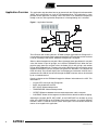
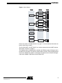
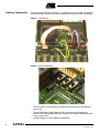
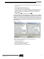
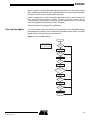
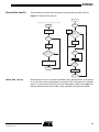
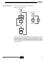
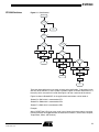
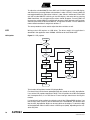
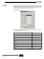
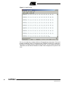
AVR064: STK502 – A Temperature Monitoring
System with LCD Output
Features
•
•
•
•
•
Presenting Data on an LCD Display
Temperature Measurement
Real Time Clock (RTC)
UART Communication with a PC
PWM Implementation
Introduction
8-bit
Microcontroller
Application
Note
The STK502 board is a top module designed to add ATmega169 support to the
STK500 development board from Atmel. STK500 and STK502 provide all hardware
needed to get started developing with the ATmega169. This application note is an
example of how to use the ATmega169 and the STK502.
It includes:
•
ATmega169 code example written in IAR EWAVR 2.27.
•
Flowcharts explaining the code.
•
Instruction on how to configure the STK502.
•
A pre-programmed ATmega169 including the example in this application note is
shipped with each STK502 kit.
•
The source code is found on the “AVR Technical Library” CD shipped with the
STK502. It can also be found on the Atmel web site, www.atmel.com.
Rev. 2529A–AVR–11/02
1
Application Overview
This application note describes how to get started with the ATmega169 microcontroller
(MCU), the first AVR that has a built in LCD controller/driver. This application is a temperature control application, including a Real Time Clock. It will monitor the temperature
through a sensor, and regulate the temperature if a heating/cooling unit is attached.
Figure 1. Application Overview
ATmega169
32 kHz
U
A
R
T
L
C
D
STK500
SWITCHES
Timer2
I/O
ADC
NTC
Thermistor
STK500
LEDS
Heating/
Cooling
Unit
The LCD starts with scrolling the text: “STK502 example application for ATmega169”. It
is required that the example code is programmed into the ATmega169 and the hardware
is set up according to the section “Hardware Configuration” on page 6.
Select a desired temperature set point. When the temperature goes below this set point
value, the Heater I/O pin will go high, and a LED on STK500 will flash. When the temperature goes above the set point value, the Cooler I/O pin will go high, and another
LED on the STK500 will flash. The duty cycle of the LED flashing will vary with the actual
temperature deviation from the set point (the greater the deviation is, the brighter the
LEDs will shine) The LCD will display time and temperature information. All data that is
presented on the LCD will also be sent through the UART-interface and can be received
by etc a standard terminal.
Pressing a button on the STK500 will toggle the different information on the LCD. This
information is:
•
CLOCK: RTC running on the ATmega169
•
DATE: Calculated from the RTC
•
SET POINT: Selected temperature
•
TEMPERATURE: Measured temperature
•
OFFSET: Difference between the measured temperature and the set point
•
CONTRAST: Shows all the segments available with the default hardware strapping.
Adjusting the CLOCK, DATE, SET POINT, or the CONTRAST can be done by using
three of the SWITCHES on the STK500. Since these switches are used for different
functions, there is a need for a menu system. See Figure 2 for an overview of how the
menus are arranged in this application.
2
AVR064
2529A–AVR–11/02
AVR064
Figure 2. Menu System
Menu 1
Menu 2
Menu 3
+
HOUR
+
CLOCK
MINUTE
+
SECOND
-
+
DAY
+
DATE
MONTH
+
YEAR
-
+
SET POINT
SET POINT
-
TEMPERATURE
OFFSET
+
CONTRAST
CONTRAST
-
Please see section “STK500 Switches” on page 17, for more detailed information on
how to use the menu system.
The CLOCK, DATE, and SET POINT can also be adjusted from the UART interface.
See section “Terminal” on page 21.
The implementation is designed to be used with the STK502 and the LCD display that is
included in this starterkit. For technical specifications and the LCD bit mapping please
refer to the “STK502 User Guide” and for more information on the LCD driver see application note “AVR065: LCD Driver for the STK502 LCD”.
3
2529A–AVR–11/02
Hardware
Description
ATmega169
ATmega169 is an ultra low power AVR 8-bit RISC microcontroller. It includes 16K byte
Self-programming Flash Program memory, 1K byte SRAM, 512 byte EEPROM, and 8channel 10-bit A/D converter, JTAG interface for On-chip Debugging and 4 X 25 Segment LCD driver. It can do up to 1 MIPS throughput at 1 MHz for ATmega169V, or 4
MIPS throughput at 4 MHz for the ATmega169L.
The ATmega169 is an excellent choice for low power applications that require user
interaction (LCD + keyboard) and the possibility to interface analog sensors etc.
AREF
PF0 (ADC0)
PF1 (ADC1)
PF2 (ADC2)
PF3 (ADC3)
PF4 (ADC4/TCK)
PF5 (ADC5/TMS)
PF6 (ADC6/TDO)
PF7 (ADC7/TDI)
GND
VCC
PA0 (COM0)
PA1 (COM1)
PA2 (COM2)
60
59
58
57
56
55
54
53
52
51
50
49
GND
61
63
62
AVCC
64
Figure 3. ATmega169
48 PA3 (COM3)
LCDCAP
1
(RXD/PCINT0) PE0
2
(TXD/PCINT1) PE1
3
(XCK/AIN0/PCINT2) PE2
4
45 PA6 (SEG2)
47 PA4 (SEG0)
INDEX CORNER
46 PA5 (SEG1)
(AIN1/PCINT3) PE3
5
44 PA7 (SEG3)
(USCK/SCL/PCINT4) PE4
6
43 PG2 (SEG4)
(DI/SDA/PCINT5) PE5
7
(DO/PCINT6) PE6
8
42 PC7 (SEG5)
41 PC6 (SEG6)
ATmega169
(CLKO/PCINT7) PE7
9
40 PC5 (SEG7)
(SS/PCINT8) PB0
10
39 PC4 (SEG8)
(SCK/PCINT9) PB1
11
38 PC3 (SEG9)
(MOSI/PCINT10) PB2
12
37 PC2 (SEG10)
(MISO/PCINT11) PB3
13
36 PC1 (SEG11)
25
26
27
28
29
(ICP/SEG22) PD0
(INT0/SEG21) PD1
(SEG20) PD2
(SEG19) PD3
(SEG18) PD4
(SEG15) PD7 32
24
(TOSC1) XTAL1
(SEG16) PD6 31
23
(TOSC2) XTAL2
(SEG17) PD5 30
22
GND
33 PG0 (SEG14)
VCC 21
16
(RESET) PG5 20
(OC1B/PCINT14) PB6
(T0/SEG23) PG4 19
35 PC0 (SEG12)
34 PG1 (SEG13)
(T1/SEG24) PG3 18
14
15
(OC2A/PCINT15) PB7 17
(OC0A/PCINT12) PB4
(OC1A/PCINT13) PB5
See ATmega169 data sheet for more information.
STK502
The STK502 board is a top module designed to add ATmega169 support to the STK500
development board from Atmel.
STK502 includes connectors and hardware allowing full utilization of the new features of
the ATmega169 including an LCD display, while the Zero Insertion Force (ZIF) socket
allows easy use of TQFP packages for prototyping.
Figure 4. STK502 Top Module for STK500
See the STK502 User Guide for more information about the STK502.
4
AVR064
2529A–AVR–11/02
AVR064
LCD Display
Liquid Crystal Displays (LCDs) are categorized as non-emissive display devices. In that
respect, they do not produce any form of light like a Cathode Ray Tube (CRT). LCDs are
composed of a polarized liquid crystalline material in between two plates of glass. Typically, one plate is called the common or backplane, and the other is called a segment or
frontplane. In a reflective LCD panel (one that has no back light) a voltage difference
applied across the two electrodes will result in a polarization which will prevent the light
from reflecting back to the observer. This will appear as a dark segment and is, therefore, considered ON. A lack of voltage difference will allow the light to reflect back and is
considered OFF.
For more information on the LCD driver, see application note “AVR065: LCD Driver for
the STK502 LCD"
NTC Thermistor
Various types of sensors can be used to measure temperature. One of these is the thermistor, or temperature-sensitive resistor. Most thermistors have a negative temperature
coefficient (NTC), meaning the resistance goes up as temperature goes down. Of all
passive temperature measurement sensors, thermistors have the highest sensitivity
(resistance change per degree of temperature change). Thermistors do not have a linear temperature/resistance curve.
The NTC thermistor used with this application has a resistance of 10 kΩ at 25°C (TAMB),
beta-value of 3450 and a tolerance of ±1%. The voltage over the NTC can be found
using the A/D converter in the ATmega169. See the ATmega169 data sheet for how to
use the ADC. And by the use of the following equation, the temperature can be
calculated.
β
– T ZERO
Temperature = ----------------------------------------------------------------V ADC
β
ln --------------------------------- + -------------V REF – V ADC
T AMB
β
= 3450
VADC
= Voltage calculated from the A/D conversion
VREF
= 1.263V
TZERO = 273°K
TAMB = 298°K (273° + 25°)
5
2529A–AVR–11/02
Hardware Configuration
In order to make the example code work, it is required to set up the cables and switches
in the correct order. Figure 5 and Figure 6 shows how to set up the cables and switches.
Figure 5. Cable Settings
Figure 6. Switch Configuration
6
•
Connect PORTE on the STK502 to the SWITCHES header on the STK500 with a
10-pin cable.
•
Connect PB5/PB6 to LED5/LED6, PB4/PB7 to respectively Heating/Cooling
element. If no heating/cooling element is available, just connect PORTB to the LEDs
using a 10-pin cable.
•
Connect PE0/PE1 on the STK500 to the RXD/TXD.
AVR064
2529A–AVR–11/02
AVR064
•
Connect the “Segment pins from ATmega169” to the “STK502 LCD pins” with the
34-pin cable.
•
Place a jumper on the 2-pin header “19 24”
•
Insert the NTC thermistor in the screw terminal.
•
All of the three switches on the STK502 should be in the position towards the twoscrew terminal block, i.e., the TOSC switch should be in the TOSC position, the
AREF switch should be in the VREF position and the PF[1:0] should be in the
SENSOR position.
•
Connect PG5 and RST with a jumper, on PORTG/RST.
And most importantly, insert the ATmega169 in the ZIF-socket. The ATmega169 that
comes with the STK502 kit, is pre-programmed with the example code. If it is required to
re-program the ATmega169, see the STK502 User Guide for help on this topic. The
AVR064.hex file that should be programmed into the ATmega169 can be found on the
“AVR Technical Library” CD that comes with the STK502, and on the ATMEL web site,
www.atmel.com. If the ATmega169 is re-programmed make sure the fuses are set up
according to Figure 7.
Figure 7. Fuse Settings
As Figure 7 describes, the only fuses that should be programmed are:
•
Brown-out Detection disabled
•
JTAG Interface Enabled
•
Serial Program downloading (SPI) enabled
•
Boot Flash Section size = 1024 words
•
Internal RC Oscillator; Start-up time 6CK + 65 ms
7
2529A–AVR–11/02
ATmega169 Firmware
The firmware that realizes the temperature control application is written in IAR EWAVR
2.27b. The timing related functions are written for an ATmega169 running at 1 Mhz
except the RTC clock and the LCD frame rate which is clocked from an external 32 kHz
crystal. The crystal is mounted on the STK502 board.
Interrupts Used
LCD Start of Frame
In this interrupt the data from the LCD_displayData buffer is latched to the LCD Data
Registers. The variable LCD_Blink toggles every time this interrupt occurs. The interrupt
is dependent of the external 32 kHz crystal.
Timer/Counter2 Overflow
This interrupt is used to increment the variable SECOND, which the whole RTC clock
builds on. Timer/Counter2 is clocked asynchronous from the 32 kHz and is therefore
independent of the clock frequency.
USART0, RX Complete
This interrupt takes care of incoming data from the UART interface.
USART0, Data Register Empty This interrupt transmits data out through the UART interface.
8
AVR064
2529A–AVR–11/02
AVR064
Main Loop
Figure 8 shows the main loop.
Figure 8. Main Loop
Initialize
Time and
Date Update
Temperature
Calculation
and Action
Store Data
from
Receive
Buffer
Send Data
from
Transmit
Buffer
Check
Status on
STK500
Buttons
Update LCD
9
2529A–AVR–11/02
Initialize
After a Reset the firmware will initialize the ATmega169 and its integrated peripherals.
The initialization runs only one time after a Reset.
Figure 9. Initialize
Initialize
Set PORTB as Output.
Set PORTE as Input.
Set Up Timer1 with PWM.
Phase Correct, 10-bit.
Set Up the Real Time Clock,
using Timer2 in Asynchronous
Mode.
Set Up the UART.
Baudrate = 9600 @ 1Mhz
Set Up the ADC
Set Up the LCD with 1/4 Duty
Cycle and 1/3 Bias.
Enable All Segments.
Set Up Data for the LCD
Display. Scrolling Text.
Return
PORTB is set as output and should be connected to the LEDS on STK500. PB5 (OC1A)
and PB6 (OC1B) shows the offset between measured temperature and selected temperature set point. PB4 and PB7 are heating and cooling pins respectively. Connect a
heating and cooling element to these pins.
DDRE is set as input and should be connected to the SWITCHES on the STK500. PE7,
PE6, and PE5 are used to select what information should be displayed on the LCD and
adjusting Time/Date, temperature set point and the LCD contrast.
Timer/Counter1 is set up with PWM to use on the OC1A/OC1B (PB5/PB6) pins.
Enable Timer/Counter2 with asynchronous operation, for the RTC. By using an external
32 kHz crystal the RTC can run independently of the ATmega169 system clock, and will
also run during sleep.
Set up the UART with both RX and TX enable, baud rate 9600 @ 1 MHz, asynchronous
operation, 8-bit character size, 1 stop bit and Disable Parity mode.
10
AVR064
2529A–AVR–11/02
AVR064
Set up the ADC in Single Ended mode. Differential mode can be selected by setting
ADC_init(Differential) instead of ADC_init(SingleEnded) in the source code. Disable digital input on PORTF and run a dummy ADC conversion.
Enable all segment pins on the ATmega169. Select the 32 kHz as clock source for the
LCD, and set the prescaler bits. Select 1/4 duty cycle and 1/3 bias. Set up
Timer/Counter0 Compare Match interrupt to give the required delays for the scrolling
and blinking speed of the information on the LCD display.
Start scrolling the initial string over the LCD display.
Time and Date Update
This routine updates the clock and date according to the variable SECOND that gets
incremented every second in the Timer/Counter2 Overflow interrupt routine. The whole
update routine is self-explaining from the flow-chart.
Figure 10. Time and Date Update
Time_update
The Variable SECOND is
Incremented in the Timer2
Overflow Interrupt Routine.
SECOND
Larger than
59?
NO
YES
Increment MINUTE
Clear SECOND
MINUTE
Larger than
59?
NO
YES
Increment HOUR
Clear MINUTE
HOUR
Larger than
23?
NO
YES
Increment DAY
Clear HOUR
DAY
Larger than Number
of Days in Month? (check
if Leap Year)
NO
YES
Increment MONTH
Set DAY = 1
MONTH
Larger than
12?
NO
YES
Increment YEAR_LO
Set MONTH = 1
YEAR_LO
Larger than
99?
YES
NO
Increment YEAR_HI
Clear YEAR_LO
Return
11
2529A–AVR–11/02
Temperature Calculation
In this function the voltage over the NTC thermistor will be measured and the temperature calculated.
Figure 11. Temperature Calculation
ADC_conversion
Run an
Analog to
Digital
Conversion.
Increment the
Number of A/D
Converions
Measured
Temperature 32
Times?
NO
YES
Calculate the Voltage
from the ADC Value,
and Use it in a Formula
to Calulate the
Corresponding
Temperature.
Find the Difference
Between the Measured
Temperature and the
Setpoint, and if
Necessary, set Heating
or Cooling Pin.
Return
Start by doing an A/D conversion. The average of 32 ADC results is used in a formula to
calculate the corresponding temperature. The heating or cooling pin are set depending
on the difference between the calculated temperature and the temperature set point.
The temperature set point is selected by the user. The bigger the difference is, the
brighter the heating or cooling LED will shine.
12
AVR064
2529A–AVR–11/02
AVR064
Receive Data from PC
These routines take care of data coming from the PC through the UART interface.
Figure 12. Receive Packet from PC
Store_RX_data
Interrupt [USART_RXC_vect] Void USART0_RXC_interrupt (Void)
RX_Packet
Complete?
RXC Interrupt
NO
YES
Read the UDR0 Register
which Contains the
Received Byte.
Preamble
Received?
There May Be Up to
Three ASCII Bytes to
Get One HEX Byte
Byte in
Receive Buffer = 0x0D YES
or 0x20? (End of Packet
or New Byte)
NO
NO
YES
Convert ASCII
Byte to HEX
Store Received
Byte in Receive
Buffer
Received
Byte = 0x0D?
(ascii Value for Line Feed,
End of Packet)
Any Byte
Converted?
NO
NO
YES
YES
Store the HEX
Byte to SRAM
Preamble Received = FALSE
RX_Packet Complete = TRUE
NO
Return from
Interrupt
Byte in
Receive Buffer
= 0x0D?
YES
Set RX_Packet
Complete = FALSE
Return
USART_RXC_interrupt
Receiving data from the PC is done in the USART_RXC_interrupt routine. It will discard
all data until the correct preamble bytes are received. Then it will store the succeeding
bytes in a receive buffer until the byte for Line Feed appears (ASCII value: 0x0D) This
indicates the end of the packet and RX_Packet_complete Flag will be set to TRUE.
13
2529A–AVR–11/02
Store_Rx_data
The packet is then converted from ASCII to hexadecimal. One HEX-byte can contain 1 3 ASCII bytes. ASCII-bytes that belong to different HEX-bytes are separated by an
ASCII-space (0x20). The converted HEX-bytes get continuously stored in the correct
place in SRAM until the Line-Feed byte appears, which is the end of the packet.
Table 1. Receive Packet from PC
Preamble “STK502”
6 byte
ASCII-space (0x20)
1 byte
HOUR
2 byte
ASCII-space (0x20)
1 byte
MINUTE
2 byte
ASCII-space (0x20)
1 byte
SECOND
2 byte
ASCII-space (0x20)
1 byte
DATE
2 byte
ASCII-space (0x20)
1 byte
MONTH
2 byte
ASCII-space (0x20)
1 byte
YEAR_HI
2 byte
ASCII-space (0x20)
1 byte
YEAR_LO
2 byte
ASCII-space (0x20)
1 byte
SET_POINT
2 byte
ASCII-carriage return (0x0D)
2 byte
ASCII-line feed (0x0A)
2 byte
Transferring the data in ASCII allows a standard terminal to be used on the PC.
14
AVR064
2529A–AVR–11/02
AVR064
Transmit Packet to PC
These routines transmit the data from ATmega169 to the PC.
Figure 13. Transmit Packet to PC
Send_TX_data
Ongoing
Transmission?
interrupt [USART0_UDRE_vect] void USART0_UDRE_interrupt(void)
YES
UDRE Interrupt
NO
Load Preamble Bytes
in Transmit Buffer
Bytes Left to
Send?
NO
YES
Load 0x20, ASCII: "Space"
in Transmit Buffer.
Transmit
One Byte
Disable
UDRE
Interrupt
Convert One
HEX Byte to
2-3 ASCII Bytes.
Return from
Interrupt
YES
HEX Bytes
Left to Convert?
NO
Load 0x0D,
ASCII:"Line Feed" in
the End of Packet
Enable UDRE
Onterrupt, that will
Start the Transfer.
Return
A transmit packet starts with the preamble bytes, and then the HEX-bytes that are to be
transmitted get converted to ASCII-bytes and loaded in the packet. Between each HEXbyte that gets converted, an ASCII-byte for space (0x20) is inserted. At the end of the
packet, an ASCII-byte for Line Feed is added to indicate the end of frame. The transmission starts by enabling the UDRE interrupt. When all bytes are transmitted the UDRE
interrupt gets disabled.
15
2529A–AVR–11/02
Table 2. Transmit Packet to PC
16
Preamble “STK502”
6 byte
ASCII-space (0x20)
1 byte
HOUR
2 byte
ASCII-space (0x20)
1 byte
MINUTE
2 byte
ASCII-space (0x20)
1 byte
SECOND
2 byte
ASCII-space (0x20)
1 byte
DATE
2 byte
ASCII-space (0x20)
1 byte
MONTH
2 byte
ASCII-space (0x20)
1 byte
YEAR_HI
2 byte
ASCII-space (0x20)
1 byte
YEAR_LO
2 byte
ASCII-space (0x20)
1 byte
SET_POINT
2 byte
ASCII-space (0x20)
1 byte
TEMP_HIGHBYTE
2 byte
ASCII-space (0x20)
1 byte
TEMP_LOWBYTE
2 byte
ASCII-space (0x20)
1 byte
OFFSET
2 byte
ASCII-space (0x20)
1 byte
Firmware revision
2 byte
ASCII-carriage return (0x0D)
2 byte
ASCII-line feed (0x0A)
2 byte
AVR064
2529A–AVR–11/02
AVR064
STK500 Switches
Figure 14. CheckButtons
CheckButtons
Buttons
Released from
Last Time?
No
Yes
Read
Buttons
Menu 2
Active?
Return
Yes
No
A
Button
A, B, or C?
Menu 3
Active?
C
No
B
Shift
Menu1
Activate
Menu 2
Yes
Deactivate
Menu 1
A
Button
A, B, or C?
C
B
Run
LCDsetupData
Shift
Menu 2
Activate
Menu 3
Deactivate
Menu 2
A
Button
A, B, or C?
C
Return
B
Run
LCDsetupData
Increase
Value
Decrease
Value
Deactivate
Menu 3
Return
Run
LCDsetupData
Return
Return
Return
There are three switches that are used as inputs to the application. To do several tasks
with only three switches, a menu system is needed. Figure 14 shows three menus in a
hierarchy, which are used in this code. See Figure 2 for the a overview of the menus.
Figure 14 refers to ButtonA/B/C, in the application these buttons can be found at:
“ButtonA” is SW7 which is connected to PE7.
“ButtonB” is SW6 which is connected to PE6.
“ButtonC” is SW5 which is connected to PE5.
Example:
After a RESET the LCD is set up to scroll a text. None of the three menus are active.
Pressing the SW7 will toggle between the alternatives in Menu 1 (Clock, Date, Set point,
Temperature, Offset, and Contrast)
17
2529A–AVR–11/02
To adjust the variable MINUTE: Press SW7 until “CLOCK” appears in the LCD display,
and select this by pressing SW6 to activate Menu 2 under “CLOCK”. Pressing SW7 will
now toggle between the alternatives in Menu 2, Hour, Minute, and Second. Press SW7
until the variable MINUTE is blinking in the LCD display, and select this by pressing
SW6. Now Menu 3 is activated and the colons should disappear. Pressing SW7 will
increase the variable MINUTE and SW6 will decrease. When desired value has been
selected, press SW5 to deactivate Menu 3, and go back to Menu 2. Press SW5 once
more to deactivate Menu 2 and go back to Menu 1.
The same procedure can be used to adjust the other variables as well.
LCD
Writing to the LCD requires an LCD driver. The driver used in this application is
described in the application note “AVR065: LCD Driver for the STK502 LCD”.
LCD Update
Figure 15. LCD_update
LCD_update
No
LCD_
updateComplete
= TRUE?
Yes
Set
LCD_updateRequired
= FALSE
No
Write Data
fromTransmitBuffer?
Yes
Scrolling
Text?
No
Set
Specialsegments
if Required
Yes
Clear All
Special Segments
Load One
Byte from
Transmit Buffer
Enable All
Segments
Activate Blinking
if that is Required
Go to
LCDscrollMSG
Function.
Write the
Digit to
LCD_displayBuffer
Set
LCD_updateComplete
= FALSE
Yes
Six Digits
Written to
Buffer?
No
Set
LCD_updateRequired
= TRUE
Return
This function will load data into the LCD_displayBuffer.
First check if the LCD has been updated with the data already in the LCD_displayBuffer.
If so, set the LCD_update required to FALSE. This will prevent the LCD to be updated
with incomplete data, if an LCD Start of Frame interrupt should occur during this
function.
If a text-string is to be scrolled, clear display and call the LCDscrollMSG function. If no
text to scroll, check if there is data to write from the TransmitBuffer, and load the data
into the LCD_displayBuffer. Digits can be set to blink on the display. To do this the digit
will be loaded with either its data value or a ASCII-space (0x20), depending on the variable LCD_Blink.
18
AVR064
2529A–AVR–11/02
AVR064
After the LCD_displayBuffer has been updated, the LCD_updatedComplete will be set
to FALSE, and LCD_updateRequired to TRUE. This will cause the LCD_displayBuffer to
be written to the LCD in the LCD Start of Frame interrupt.
Scroll Function
Figure 16. LCDscrollMsg
LCDscrollMsg
String
Pointer at
the End of
String?
Yes
No
Write Six
Characters from the
String to the
LCD_displayBuffer
LCD
Display
Empty?
Yes
No
Increment
String Pointer
Add one "Space" and
Write the Remaining
Characters from
String to the
LCD_displayBuffer
Clear
String Counter
If not Set to
Infinite Scrolling,
Decrement the
NumberOfScroll
Variable
Return
This function shifts the six digits on the LCD one step to the left. An external delay or
interrupt is needed in order to get the right speed of the scrolling text. The scroll function
uses a pointer to keep track of what characters to shift in and out of the LCD. When all
the six digits have been updated, the pointer gets incremented by one in order to shift
the text-string one step the next time this function is called.
If the pointer has reached the end of the string, the LCD has to be filled up with one
ASCII-space at the time until all of the six digits are blank. This will “fade” out the text
string.
19
2529A–AVR–11/02
LCD Set-up Data
Figure 17. LCDsetupData
LCDsetupData
Menu 1
Active?
No
Yes
Load Welcome
String and
Activate Infinite
Scrolling
Menu 2
Active?
No
Yes
Menu 3
Active?
Yes
No
Load a String
(Depending on
Menu 1) to be
Scrolled Once.
Enable
Colons
Enable
Colons
Disable
Colons
Return
If Menu 1 isn’t active the welcome string will scroll over the LCD. If Menu 1 is active but
not Menu 2, the corresponding string will be scrolled once over the LCD and then the
data belonging. If Menu 2 is active but not Menu 3, just enable the colons. And if Menu 3
is active, disable the colons to indicate that the current variable can now be adjusted.
20
AVR064
2529A–AVR–11/02
AVR064
Terminal
All temperature and time information is transmitted through the UART-interface. A program on a PC can receive this data by connecting a serial cable between the “RS-232
SPARE” on the STK500 and a comport on the PC. A standard terminal can be used,
e.g, HyperTerminal. Set up the terminal as shown in Figure 18.
Figure 18. Port Settings
Press the connect button and the data from the ATmega169 should appear as in Figure
19. The data is presented according to Table 1.
Table 3. Transmit Packet from ATmega169 according to Figure 19
Preamble
STK502
Hour
15
Minute
14
Second
23
Day
04
Month
11
Yearhigh
20
Yearlow
02
Set point
25
°C high byte
20
°Clow byte
23
Offset
04
Versions number
01
21
2529A–AVR–11/02
Figure 19. HyperTerminal
One can also adjust the variables within the ATmega169 from the terminal. This has to
be done according to Table 1. For example, write: “STK502 14 37 02 25 11 20 02 24” in
the terminal, and press enter to indicate end of frame. This will adjust the clock to
14h37m02s, the date will be November 25, 2002. And the temperature set point will be
24°C.
22
AVR064
2529A–AVR–11/02
Atmel Headquarters
Atmel Operations
Corporate Headquarters
Memory
2325 Orchard Parkway
San Jose, CA 95131
TEL 1(408) 441-0311
FAX 1(408) 487-2600
Europe
Atmel Sarl
Route des Arsenaux 41
Case Postale 80
CH-1705 Fribourg
Switzerland
TEL (41) 26-426-5555
FAX (41) 26-426-5500
Asia
Room 1219
Chinachem Golden Plaza
77 Mody Road Tsimhatsui
East Kowloon
Hong Kong
TEL (852) 2721-9778
FAX (852) 2722-1369
Japan
9F, Tonetsu Shinkawa Bldg.
1-24-8 Shinkawa
Chuo-ku, Tokyo 104-0033
Japan
TEL (81) 3-3523-3551
FAX (81) 3-3523-7581
2325 Orchard Parkway
San Jose, CA 95131
TEL 1(408) 441-0311
FAX 1(408) 436-4314
RF/Automotive
Theresienstrasse 2
Postfach 3535
74025 Heilbronn, Germany
TEL (49) 71-31-67-0
FAX (49) 71-31-67-2340
Microcontrollers
2325 Orchard Parkway
San Jose, CA 95131
TEL 1(408) 441-0311
FAX 1(408) 436-4314
La Chantrerie
BP 70602
44306 Nantes Cedex 3, France
TEL (33) 2-40-18-18-18
FAX (33) 2-40-18-19-60
ASIC/ASSP/Smart Cards
1150 East Cheyenne Mtn. Blvd.
Colorado Springs, CO 80906
TEL 1(719) 576-3300
FAX 1(719) 540-1759
Biometrics/Imaging/Hi-Rel MPU/
High Speed Converters/RF Datacom
Avenue de Rochepleine
BP 123
38521 Saint-Egreve Cedex, France
TEL (33) 4-76-58-30-00
FAX (33) 4-76-58-34-80
Zone Industrielle
13106 Rousset Cedex, France
TEL (33) 4-42-53-60-00
FAX (33) 4-42-53-60-01
1150 East Cheyenne Mtn. Blvd.
Colorado Springs, CO 80906
TEL 1(719) 576-3300
FAX 1(719) 540-1759
Scottish Enterprise Technology Park
Maxwell Building
East Kilbride G75 0QR, Scotland
TEL (44) 1355-803-000
FAX (44) 1355-242-743
e-mail
[email protected]
Web Site
http://www.atmel.com
© Atmel Corporation 2002.
Atmel Corporation makes no warranty for the use of its products, other than those expressly contained in the Company’s standard warranty
which is detailed in Atmel’s Terms and Conditions located on the Company’s web site. The Company assumes no responsibility for any errors
which may appear in this document, reserves the right to change devices or specifications detailed herein at any time without notice, and does
not make any commitment to update the information contained herein. No licenses to patents or other intellectual property of Atmel are granted
by the Company in connection with the sale of Atmel products, expressly or by implication. Atmel’s products are not authorized for use as critical
components in life support devices or systems.
ATMEL ® and AVR® are the registered trademarks of Atmel.
Other terms and product names may be the trademarks of others.
Printed on recycled paper.
2529A–AVR–11/02
0M