1
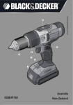
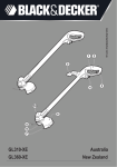
QUICK CONNECT SYSTEM
www.blackanddecker.com.au
ROuTER
ATTAChmENT
Australia
BDCMTR-XE
New Zealand
PARTS AND FEATURES
figure A
1. Router attachment
2. Spindle lock button
3. Active lock-off button
4. Nut and Collet
5. Depth stop bar
6. Depth of cut scale
7. Chip shield
8. Base
Not shown:
Wrench
A
1
3
2
5
6
7
8
4
Additional accessories are available at extra cost
from your local Black & Decker dealer.
2
(Original instructions)
ENGLISH
Intended use
Your Black & Decker multi-purpose tool has been designed for a wide range of DIY applications.
Using the router head , this tool is intended for routing wood and wood products.
This tool is intended for consumer use only.
Safety instructions
General power tool safety warnings
:
WARNING! To reduce the risk of injury, the user must read the instruction manual.
General power tool safety warnings
@
@
WARNING! Read all safety warnings and all instructions. Failure to follow the warnings and
instructions listed below may result in electric
WARNING! Read all safety warnings and all instructions provide with your power unit (BDCDMT108-XE,
BDCDMT180-XE) before using this accessory.
WARNING: Read all safety warnings and all instructions. Failure to follow the
warnings and instructions may result in electric shock, fire and/or serious injury.
SpecificSafetyruleS
• Hold powertoolbyinsulatedgrippingsurfaces,becausethecuttermaycontactitsowncord.
Cutting a “live” wire may make exposed metal parts of the power tool “live” and shock the operator.
• useclampsoranotherpracticalwaytosecureandsupporttheworkpiecetoastableplatform. Holding the
work by your hand or against the body leaves it unstable and may lead to loss of control.
• Keep handles dry, clean, and free from oil and grease. This will enable better control of the tool.
• Keephandsawayfromcuttingarea.neverreachundertheworkpieceforanyreason.Keep
therouterbasefirmlyincontactwiththeworkpiecewhencutting.holdtherouteronlybythe
handles. These precautions will reduce the risk of personal injury.
Kickbackisasuddenreactiontoapinched,boundormisalignedrouterbit,causingan
uncontrolled router to lift up and out of the workpiece toward the operator.
• Keepyourbodypositionedtoeithersideoftherouter,butnotinlinewiththerouterbit. KICKBACK
could cause the router to jump backwards (see causesandOperatorpreventionofKickback
• Missingstopscancausekickback. Use back and/or front stops fixed to the fence when doing
stopped work.
• Use sharp cutters. Dull cutters may cause the router to swerve or stall under pressure.
• nevertouchthebitimmediatelyafteruse. It may be extremely hot.
• besurethatthemotorhasstoppedcompletelybeforeyoulaytherouterdown. If the cutter head
is still spinning when the tool is laid down, it could cause injury or damage.
• besurethattherouterbitisclearoftheworkpiecebeforestartingthemotor. If the bit is in contact
with the workpiece when the motor starts it could make the router jump, causing damage or injury.
• Onlyuserouterbitswithashankdiameterequaltothesizeofthecolletinstalledinthetool.
• Onlyuserouterbitssuitablefortheno-loadspeedofthetool.
• Donotuserouterbitswithadiametergreaterthan1-3/8”(27mm). Use of larger than
recommended bits can result in a hazard.
• notintendedtobeusedwitharoutertable. Donotusethetoolinaninvertedposition.
• Donotattempttousethetoolinastationarymode.
• Makesurecolletnutissecurelytightenedtopreventrouterbitfromslippingduringuse.
3
ENGLISH
(Original instructions)
Warning: alWaySuse safety glasses. Everyday eyeglasses are NOT safety glasses. Also use
face or dust mask if drilling operation is dusty. ALWAYS WEAR CERTIFIED SAFETY EQUIPMENT:
•ANSI Z87.1 eye protection (CAN/CPA Z94.3),
•ANSI S12.6 (S3.19) hearing protection,
•NOSH/OSHA respiratory protection.
Warning:
Somedustcreatedbypowersanding,sawing,grinding,drilling,andother
construction activities contains chemicals known to the state of California to cause cancer,
birthdefectsorotherreproductiveharm.Someexamplesofthesechemicalsare:
•lead from lead-based paints,
•crystalline silica from bricks and cement and other masonry products, and
• arsenic and chromium from chemically-treated lumber.
Your risk from these exposures varies, depending on how often you do this type of work. To reduce
your exposure to these chemicals: work in a well ventilated area, and work with approved safety
equipment, such as those dust masks that are specially designed to filter out microscopic particles.
• Avoid prolonged contact with dust from power sanding, sawing, grinding, drilling, and other
constructionactivities.Wearprotectiveclothingandwashexposedareaswithsoapandwater.
Allowing dust to get into your mouth, eyes, or lay on the skin may promote absorption of harmful chemicals.
Warning: useofthistoolcangenerateand/ordispersedust,whichmaycauseserious
and permanent respiratory or other injury. Always use NOSH/OSHA approved respiratory
protection appropriate for the dust exposure. Direct particles away from face and body. Always
operate tool in well-ventilated area and provide for proper dust removal. Use dust collection
system wherever possible.
Warning: alWaySwearproperpersonalhearingprotectionthatconformstoanSi
S12.6(S3.19)duringuse. Under some conditions and duration of use, noise from this product
may contribute to hearing loss.
cauSeSanDOperatOrpreVentiOnOfKicKbacK
•Kickbackisasuddenreactiontoapinched,boundormisalignedsawblade,causingan
uncontrolled saw to lift up and out of the workpiece toward the operator.
•Whenthebladeispinchedorboundtightlybythekerfclosingdown,thebladestallsandthemotor
reaction drives the unit rapidly back toward the operator.
•Ifthebladebecomestwistedormisalignedinthecut,theteethatthebackedgeoftheblade
can dig into the top surface of the wood causing the blade to climb out of the kerf and jump back
toward the operator.
Kickbackistheresultofsawmisuseand/orincorrectoperatingproceduresorconditionsandcanbe
avoided by taking proper precautions as given below:
a) Maintainafirmgripwithbothhandsonthesawandpositionyourarmstoresist
kickbackforces.positionyourbodytoeithersideoftheblade,butnotinlinewiththe
blade.Kickback could cause the saw to jump backwards, but kickback forces can be
controlled by the operator, if proper precautions are taken.
b) Whenbladeisbinding,orwheninterruptingacutforanyreason,releasethetriggerand
holdthesawmotionlessinthematerialuntilthebladecomestoacompletestop.never
attempttoremovethesawfromtheworkorpullthesawbackwardwhilethebladeisin
motionorkickbackmayoccur.Investigate and take corrective actions to eliminate the cause of
blade binding.
c) Whenrestartingasawintheworkpiece,centerthesawbladeinthekerfandcheck
that saw teeth are not engaged into the material. If saw blade is binding, it may walk up or
kickback from the workpiece as the saw is restarted.
d) Supportlargepanelstominimizetheriskofbladepinchingandkickback. Large
panels tend to sag under their own weight. Supports must be placed under the panel on both
sides, near the line of cut and near the edge of the panel.
e) Donotusedullordamagedblades. Unsharpened or improperly set blades produce
narrow kerf causing excessive friction, blade binding and kickback.
f) bladedepthandbeveladjustinglockingleversmustbetightandsecurebefore
making cut. If blade adjustment shifts while cutting, it may cause binding and kickback.
g) useextracautionwhenmakinga“plungecut”intoexistingwallsorotherblindareas.
The protruding blade may cut objects that can cause kickback.
4
(Original instructions)
ENGLISH
SyMbOlS
The label on your tool may include the following symbols. The symbols and their definitions are as follows:
V................... volts
A ................... amperes
Hz ................ hertz
W .................. watts
................ alternating current
min ............... minutes
no.................. no load speed
............ direct current
................. Class I Construction
.................. earthing terminal
................ safety alert symbol
(grounded)
................. Class II Construction
.../min or rpm..... revolutions or reciprocation
(double insulated)
per minute
............ Read instruction manual before use
.................. Use proper respiratory protection
................. Use proper eye protection
.................. Use proper hearing protection
SaVetheSeinStructiOnS
OperatinginStructiOnS
Warning: Shockhazard. Under no circumstances should this product be used near water.
Warning:toreducetheriskofinjury,turnoffandremovebatteryfromtoolor
disconnectplugfrompowersourcebeforemakinganyadjustmentsorremovingorinstalling
attachments or accessories.
Warning:riskoflacerationsorburns. Do not touch work piece or bit immediately after
operating the tool. They can become very hot. Handle carefully. Always allow accessories and
workpiece to cool before handling.
iMpOrtant:Refer to Power Unit instruction manual before operating this tool for all safety warnings
and details on installing and removing attachments.
OperatiOn
• Toswitchthetoolon,pressthevariablespeedswitchonthepowerunit.Thetoolspeeddepends
on how far you press the switch.
• Toswitchthetooloff,releasethevariablespeedswitch.
nOte:Operate the router at full speed at all times.
nOte:Thisattachmentonlyoperatesintheforwarddirection,theforward/reversesliderofthe
Power Unit should not be able to be switch to reverse.
inStallinganDreMOVingarOuterbit
Warning: toreducetheriskofinjury,turnoffandremovebatteryfromtoolor
disconnectplugfrompowersourcebeforemakinganyadjustmentsorremovingor
installingattachmentsorchangingbits.failuretodosocouldresultinaccidentalstarting
andpossibleinjury.
bitinStallatiOnanDreMOVal(fig.b)
nOteS:
• rOuteriSnOtrecOMMenDeDfOruSeWithraiSeDpanelbitS.
• rOuteriSnOtrecOMMenDeDfOruSeinMetalcuttingapplicatiOnS.
• DOnOtuSeanyrOuterbitgreaterthan1-3/8”DiaMeter.
cautiOn: rOuterbitSareSharp,uSecareWhenhanDlingtheM.
5
ENGLISH
(Original instructions)
inStallingbitS
Warning:turntherouteroffandremove
B
Spindlelockbutton
batteryfromtoolordisconnectplugfrompower
source.
The router is equipped with a spindle lock feature
that makes changing bits easy. Lock the spindle
shaft by depressing the spindle lock button as shown
in figureb and use the supplied wrench to loosen
(counterclockwise) the collet nut.
• Keepthespindlelockbutton(2)depressedandrotate
the spindle until the spindle lock fully engages.
• Placetherouterupsidedownonasmooth,flatsurface.
• Loosenthecolletnut(4)usingthewrenchprovided.
Insert the shank of the router bit into the collet (4).
• Wheninstallingrouterbits,besuretheyareinsertedasfaraspossibleandthenpulledoutabout
1/16”(1.5mm).
• Keepthespindlelockbutton(2)depressedandtightenthecolletnutclockwise(donotover-tighten)
using the wrench provided.
nOte:iftherouterbaseissetatitsmaximumdepth,thecolletnutcannotbetightened
properly.alwaysinsurethatiftherouterbaseisadjustedtoitsmaximumdepthitmustbe
backedoffseveralrotations(counterclockwise)beforetighteningorlooseningrouterbits.
See“SettingtherouterDepth”belowforrouterbaseadjustment.
cautiOn: neVertightencOlletnutWithOuta1/4”ShanKSizebitinSerteD
intOcOllet.tODOSOMaybreaKOrDaMagecOllet.
reMOVingbitS
cautiOn: burnhazard. routerbitsgethotduringuse.allowsufficienttimeforbitto
coolbeforereplacing.
• Keepthespindlelockbutton(2)depressed.
• Placetherouterupsidedownonasmooth,flatsurface.
• Loosen(counterclockwise)thecolletnut(4)usingthewrenchprovided.
• Releasebuttonandremovebit.
cOntrOlS
Warning:toreducetheriskofinjury,donotoverloadthetool.letitworkatitsownpace.
Warning:toreducetheriskofinjury,turnoffandremovebatteryfromtoolor
disconnectplugfrompowersourcebeforemakinganyadjustmentsorremovingor
installing attachments or accessories.
SettingtherOutingDepth(fig.c)
Warning:turntherouteroffandremove
batteryfromtoolordisconnectplugfrompowersource.
1.Keepthespindlelockbutton(2)depressedand
rotate the router base (8) as shown in figurec.
Rotating the base clockwise will increase the routing
depth while rotating the base\counterclockwise will
decrease the depth. Two complete revolutions of
the base equals about 2 millimeters.
6
C
(Original instructions)
ENGLISH
2. After obtaining the desired routing depth, release the spindle lock button. Continue turning the
base until the notch under the spindle lock button (2) aligns with the next closest locking slot
in the depth of cut scale (6).
uSingtherOuter(fig.D&e)
1. Make sure that the material to be cut is clamped down and is stable enough to support the
router during operation.
2. Use both hands on the power unit to control the router, and run the router at full speed at all
times. See figureD.
3. Move the router counterclockwise when cutting outside edges. Move clockwise when cutting
inside edges. See figuree.
D
E
bitrotation(Viewfromtopofrouter)
Router travel should follow arrows
feeDingSpeeDanDrateOfcut
Variation between materials and bit configurations dictates a wide variety of feed rates. Experience is
the best measure for determining feed rate. Become familiar with the sound and feel of the router by
making practice cuts in scrap material.
The router bit rotates at a very high speed and may heat up if the router is moved too slowly through
the wood and cause burn marks. Feeding the router too fast or trying to remove too much material in
asinglepasswilloverloadthemotor.Usetwoormorepassesforextra-largecuts(over1/8”deep),
especially in hard woods.
hintSfOrOptiMuMuSe
Whenworkingonoutsideedges,movethetoolcounterclockwise(figuree).Whenworkingoninside
edges, move the tool clockwise.
• Usepilot(ballbearing)routerbitsforedgeprofilecutting.
• UseHSS(highspeedsteel)routerbitsforsoftwood.
• UseTCT(tungstencarbidetipped)routerbitsforhardwood.
Maintenance
Use only mild soap and damp cloth to clean the tool. Never let any liquid get inside the tool; never
immerse any part of the tool into a liquid.
iMpOrtant: To assure product SAFETY and RELIABILITY, repairs, maintenance, and adjustment
(other than those listed in this manual) should be performed by a qualified service dealer or other
qualified service personnel.
ACCESSORIES
wARNING: Theuseofanyaccessorynotrecommendedforusewiththistoolcouldbehazardous.
Recommendedaccessoriesforusewithyourtoolareavailablefromyourlocaldealerorauthorized
service center. If you need assistance regarding accessories, please call: 1-800-444-224
Technical
data
when operate with 18V MATRIX unit
Router
No-load speed
Weight
BDCMTR-XE
n0 0-9000/min (RPM)
405g
7
Australia & New Zealand
Stanley Black & Decker
82 Taryn Drive, Epping, VIC 3076 Australia
Tel.1800 444 224 (Aust) or Tel. 0800 339 258 (NZ)
90589524 REV-0
07/2012