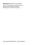
1
Instruction book for compressors
GA30 - GA37 - GA45
GA30 W - GA37 W - GA45 W
Important
1
This book applies exclusively to GA30-GA37-GA45 equipped with an electronic
regulator with a liquid crystal display. This regulator is used from following serial
number onwards
AII-310 000
2.
This book must be used together with the "User manual for electronic regulator for
GA30-GA37-GA45 compressors"
This instruction book meets the requirements for instructions specified by the
machinery directive 89/392/EEC and is valid for CE as well as non-CE labelled
machines
Registration code
Collection: APC G30-45
Tab:
38
Sequence: 0981
*2920116304*
Replaces
No. 2920 1163 03
Industrial Air Division
1994-12
B-2610 Wilrijk - Belgium
No. 2920 1163 04
Industrial Air Division
This instruction book describes how to handle the machines to ensure safe operation, optimum efficiency and long service life.
Read this book before putting the machine into operation to ensure correct handling, operation and proper maintenance from the
beginning. The maintenance schedule comprises measures for keeping the machine in good condition.
Keep the book available for the operator and make sure that the machine is operated and that maintenance is carried out according to the
instructions. Record all operating data, maintenance performed, etc. in an operator's logbook available from Atlas Copco. Follow all
relevant safety precautions, including those mentioned on the cover of this book.
Repairs must be carried out by trained personnel from Atlas Copco who can be contacted for any further information.
In all correspondence always mention the type and the serial number, shown on the data plate.
For all data not mentioned in the text, see sections "Preventive maintenance schedule" and "Principal data".
The company reserves the right to make changes without prior notice.
Contents
Page
1 Leading particulars ................................................................ 3
1.1 General description ......................................................... 3
1.1.1 Air flow ................................................................ 3
1.1.2 Oil system ........................................................... 3
1.1.3 Cooling and condensate drain systems .............. 5
1.2 Unloading/loading system ............................................... 5
1.2.1 Unloading ............................................................ 5
1.2.2 Loading ............................................................... 5
1.3 Electrical system ............................................................. 8
1.4 Electronic control module ................................................ 8
1.4.1 Electronic regulator ........................................... 11
1.4.2 Control panel ..................................................... 12
1.5 Electric cabinet .............................................................. 13
1.6 Air dryer on GA Full-feature .......................................... 13
1.6.1 Compressed air circuit ...................................... 13
1.6.2 Refrigerant circuit .............................................. 14
1.6.3 Automatic regulation system ............................. 14
1.6.4 Dryer control and safety devices ....................... 14
2 Operating instructions ........................................................ 15
2.1 Initial start-up ................................................................ 15
2.1.1 Remarks ............................................................ 15
2.1.2 Outdoor/altitude operation ................................ 15
2.1.3 Moving/lifting ..................................................... 15
2.1.4 Cooling water requirements .............................. 15
2.1.5 Initial start-up .................................................... 15
2.2 Before starting ............................................................... 16
2.3 Starting .......................................................................... 16
2.4 During operation ............................................................ 17
2.4.1 Checking the display ......................................... 17
2.5 Manual control ............................................................... 18
2.6 Stopping ........................................................................ 18
2.7 Taking out of operation at end of compressor life cycle 18
3 Maintenance ......................................................................... 19
3.1 Compressor motor ........................................................ 19
3.2 Preventive maintenance schedule for the compressor.. 19
2
Page
3.3 Oil and oil filter change interval ..................................... 19
3.4 Oil specifications ........................................................... 19
3.4.1 Atlas Copco Roto-injectfluid .............................. 19
3.4.2 Mineral oil for hydraulics ................................... 19
3.4.3 Synthetic hydrocarbon lubricant ....................... 19
3.5 Oil change ..................................................................... 21
3.6 Oil filter change ............................................................. 22
3.7 Storage after installation ............................................... 22
3.8 Service kits .................................................................... 22
4 Adjustments and servicing procedures ............................ 22
4.1 Air filter .......................................................................... 22
4.1.1 Recommendations ............................................ 22
4.1.2 Servicing ........................................................... 22
4.2 Coolers .......................................................................... 22
4.3 Safety valve ................................................................... 23
4.4 Fan control switch on GA Full-feature ........................... 24
4.5 High pressure shut-down switch on GA Full-feature ..... 24
4.6 Expansion valve on GA Full-feature .............................. 24
5 Problem solving ................................................................... 24
6 Principal data ....................................................................... 26
6.1 Readings on display ...................................................... 26
6.2 Settings of switches and safety valve ............................ 26
6.3 Settings of motor overload relay and fuses ................... 27
6.4 Settings of fan motor circuit breaker ............................. 27
6.5 Compressor specifications ............................................ 27
6.5.1 Reference conditions ........................................ 27
6.5.2 Specific data of GA30 / GA30 W ....................... 28
6.5.3 Specific data of GA37 / GA37 W ....................... 28
6.5.4 Specific data of GA45 / GA45 W ....................... 29
6.6 Conversion list of SI units into British units ................... 29
7 Installation .......................................................................... 30
7.1 Dimension drawings ...................................................... 30
7.2 Electric cable section .................................................... 32
7.3 Installation proposal ...................................................... 32
7.4 Electrical connections ................................................... 35
7.5 Pictographs ................................................................... 36
2920 1163 04
Industrial Air Division
1 Leading particulars
1.1 General description
1.1.1 Air flow (Fig. 4b)
GA are stationary, single-stage, oil-injected screw compressors
driven by an electric motor. GA30, -37 and -45 are air-cooled,
whereas GA30 W, -37 W and -45 W are water-cooled.
Air drawn through filter (AF) and open inlet valve (IV) into
compressor element (E) is compressed. Compressed air and oil
flow into air receiver/oil separator (AR) via check valve (CV). The
air is discharged through outlet valve (AV) via minimum pressure
valve (Vp), air cooler (Ca) and moisture trap (MT).
GA Pack
The compressors are enclosed in a sound-insulated bodywork.
The front panel comprises an electronic control module including
the start and stop buttons. An emergency stop button is also
provided. An electric cabinet comprising the motor starters is
located behind this panel.
Check valve (CV) prevents blow-back of compressed air when the
compressor is stopped. Minimum pressure valve (Vp) prevents the
receiver pressure from dropping below a minimum pressure.
1.1.2 Oil system (Fig. 4b)
GA Full-feature
GA Full-feature compressors are additionally provided with an air
dryer integrated in the bodywork. The dryer removes moisture from
the compressed air by cooling the air to near freezing point and
automatically draining the condensate.
E1.
1.
2.
3.
4.
In air receiver/oil separator (AR), most of the oil is removed from
the air/oil mixture centrifugally. The balance is removed by oil
separator element (OS). The oil collects in the lower part of air
receiver/oil separator (AR), which serves as oil tank.
Electronic control module
Air outlet pipe
Electric cable inlet
Condensate drains
Side door
Fig. 1. General view of GA45
2920 1163 04
3
Industrial Air Division
AF.
AR.
BV.
Ca.
Co.
CV.
DP2.
DP3.
DP4.
E.
E1.
FN2.
I.
MT.
M1.
M2.
O.
OF.
Air filter
Air receiver/oil separator
Oil cooler by-pass valve
Air cooler
Oil cooler
Check valve
Oil drain plug, oil stop valve
Oil drain plug, check valve
Oil drain plug, gear casing
Compressor element
Electronic control module
Fan
Start button
Air cooler moisture trap
Compressor motor
Fan motor
Stop button
Oil filter
Fig. 2a. Front view of air-cooled GA45 Pack/Full-feature
PT20. Pressure sensor, compressed
air outlet
SV.
Safety valve
S3.
Emergency stop button
TT11. Temperature sensor, outlet of
compressor element
UA.
Unloader
Vp.
Minimum pressure valve
VP.
Oil cooler vent plug
Vs.
Oil stop valve
1.
Electric cabinet
2.
Stud and nut (to be removed)
3.
Bolt (to be removed)
4.
Compressor motor support
5.
Compressor element support
6.
Oil scavenging flexible
7.
Vibration damper
8.
Oil drain flexible
9.
Plate
10.
Condensate drain flexibles
11.
Cooling water inlet pipe
12.
Cooling water outlet pipe
13.
Compressed air pipe
Fig. 2b. Rear view of water-cooled GA45 Pack
4
Figs. 2. GA45 Pack and Full-feature
2920 1163 04
Industrial Air Division
Da.
Dm.
1.
2.
3.
Automatic condensate drain, air cooler moisture trap
Condensate drain valve, air cooler moisture trap
Pictograph, manual condensate drain
Pictograph, automatic condensate drain
Inlet for separate air dryer voltage supply
Fig. 3. Condensate outlets
The oil system is provided with a by-pass valve (BV). When the oil
temperature is below 40°C (104°F) 1), by-pass valve (BV) shuts off
the oil supply from oil cooler (Co). Air pressure forces the oil from
air receiver/oil separator (AR) through oil filter (OF) and oil stop
valve (Vs) to compressor element (E) and its lubrication points. Oil
cooler (Co) is by-passed.
By-pass valve (BV) starts opening the oil supply from cooler (Co)
when the oil temperature has increased to the above-mentioned
value. At approx. 55°C (131°F) 1) all the oil flows through the oil
cooler.
Oil stop valve (Vs) prevents the compressor element from flooding
with oil when the compressor is stopped. The valve is opened by
element outlet pressure when the compressor is started.
1.1.3 Cooling and condensate drain systems
(Figs. 2)
The cooling system comprises air cooler (Ca) and oil cooler (Co).
On air-cooled compressors, the cooling air is generated by fan
(FN2). Water-cooled compressors have a cooling water system.
The water flows through inlet pipe (11), the tubestacks of the air
cooler and oil cooler, and outlet pipe (12).
A moisture trap (MT) is provided in the air outlet system. The trap
is equipped with a valve for automatic condensate draining during
operation (Da-Fig. 3) and a manually operated valve for draining
after stopping the compressor (Dm-Fig. 3).
1) The valve starts opening at 65°C (149°F) and is fully open at
80°C (176°F) for 13 bar and 175 psi compressors.
2920 1163 04
1.2 Unloading/loading system (Figs. 4)
1.2.1 Unloading (Fig. 4a)
If the air consumption is less than the air output of the compressor,
the net pressure increases. When the net pressure reaches the
unloading pressure, solenoid valve (Y1) is de-energized. The
plunger of the valve returns by spring force:
1. The control pressure present in the chambers of loading
plunger (LP) and unloading valve (UV) is vented to atmosphere
via solenoid valve (Y1).
2. Loading plunger (LP) moves upwards and causes inlet valve
(IV) to close the air inlet opening.
3. Unloading valve (UV) is opened by receiver pressure. The
pressure from air receiver (AR) is released towards unloader
(UA).
4. The pressure is stabilized at a low value. A small amount of air
is kept drawn in through flexible (3) and is also blown to the
unloader.
Air output is stopped (0 %), the compressor runs unloaded.
1.2.2 Loading (Fig. 4b)
When the net pressure decreases to the loading pressure, solenoid
valve (Y1) is energized. The plunger of solenoid valve (Y1) moves
upwards against spring force:
1. Control pressure is fed from air receiver (AR) via solenoid valve
(Y1) to loading plunger (LP) and unloading valve (UV).
2. Unloading valve (UV) closes the air blow-off opening. Loading
plunger (LP) moves downwards and causes inlet valve (IV) to
open fully.
Air output is resumed (100 %), the compressor runs loaded.
5
Industrial Air Division
Fig. 4a. GA30/37/45 Full-feature during unloading
6
2920 1163 04
Industrial Air Division
Fig. 4b. GA30 W/37 W/45 W Pack during loading
2920 1163 04
7
Industrial Air Division
AF.
AR.
AV.
BV.
Ca.
Co.
CV.
Da.
Dm.
DP1.
DP2.
DP3.
DP4.
E.
E1.
FC.
FN2.
Gl.
1)
2)
Air filter
Air receiver/oil separator
Air outlet valve
Oil cooler by-pass valve
Air cooler
Oil cooler
Check valve
Automatic drain outlet, air cooler
moisture trap
Manual drain valve, air cooler
moisture trap
Oil drain plug, air receiver
Oil drain plug, oil stop valve
Oil drain plug, check valve
Oil drain plug, gear casing
Compressor element
Control module
Oil filler plug
Fan, compressor coolers
Oil level gauge
IV.
LP.
MT.
M1.
M2.
OF.
OS.
PT20.
Rf2.
SV.
TT11.
Inlet valve
Loading plunger
Air cooler moisture trap
Compressor motor
Motor, compressor fan
Oil filter
Oil separator element
Pressure sensor, air outlet
Restrictor
Safety valve
Temperature sensor, compressor
element outlet
TT90. Temperature sensor, dewpoint
UA.
Unloader
UV.
Unloading valve
VI.
Air filter service indicator
Vp.
Minimum pressure valve
Vs.
Oil stop valve
Y1.
Loading solenoid valve
1.
Control air flexible
2.
3.
4.
Blow-off air flexible
Flexible, blow-off air or inlet air
Oil scavenging line
On Full-feature also:
FN1. Fan, dryer condensor
M1. Refrigerant compressor
M2. Motor, condensor fan
S3.
Condensor fan control switch
S7.
High pressure shut-down switch 1)
5.
Air/air heat exchanger
6.
Air/refrigerant heat exchanger
(evaporator)
7.
Liquid separator
8.
Refrigerant/refrigerant heat
exchanger 2)
9.
Condensor
10.
Liquid receiver
11.
Expansion valve
12.
Filter
TÜV-approved compressors only
Not on dryers of type ID120
Figs. 4. Air-oil and unloading-loading systems
1.3 Electrical system
The system comprises (Figs. 2):
1.
2.
3.
4.
5.
6.
Compressor motor (M1) and fan motor (M2) 1)
Electronic control module (Fig. 7a)
Compressor start button (I) and stop button (O)
Emergency stop button (S3)
Electric cabinet (Fig. 5)
Sensors for the compressor element outlet temperature (TT11)
and for the air outlet pressure (PT20)
7. Dewpoint temperature sensor (TT90-Figs. 6) for Full-feature
compressors
8. Phase control relay (K25-Fig. 5)
K11 1X4 K25 F3 F2 F1 F7 F4 F5 F6 1X1
T2
T1
K21
1.4 Electronic control module
The control module consists of an electronic regulator and a control
panel.
F21
F032
K23
K22
Q15 1X2
See Figs. 6 for denomination of components
1) Air-cooled compressors only
8
Fig. 5. Electric cabinet (typical example)
2920 1163 04
Industrial Air Division
Fig. 6a. GA Pack / Full-feature (typical example)
2920 1163 04
9
Industrial Air Division
Fig. 6b. Dryer ID80/100 on GA Full-feature
Fig. 6c. Dryer ID120 on GA Full-feature
10
2920 1163 04
Industrial Air Division
SENSORS/LOADING SOLENOID VALVE
PT20. Pressure sensor, air outlet
TT11. Temperature sensor, compressor
element outlet
TT90. Temperature sensor, dewpoint 1)
Y1.
Loading solenoid valve
MOTORS
M1. Compressor motor
M2. Fan motor, compressor coolers
M3. Fan motor, electric cabinet 2)
K11.
K21.
K22.
K23.
K25.
Q15.
T1/T2.
1X1.
1X2.
1X3.
1X4.
ELECTRIC CABINET
F1/F6. Fuses
F7/8. Fuses 3)
F21. Overload relay, compressor motor
CONTROL MODULE (E1)
I.
Start button
K01. Blocking relay
K02. Auxiliary relay, star contactor
1)
2)
3)
4)
5)
Auxiliary contactor for dryer 1)4)
Line contactor
Star contactor
Delta contactor
Phase control relay
Circuit breaker, fan motor
Transformers
Terminal strip
Terminal strip, connection to mains
Terminal strip
Terminal strip
K03.
K04.
K05.
K10.
O.
S3.
Auxiliary relay, delta contactor
Auxiliary relay, loading/unloading
Auxiliary relay, high/low air pressure
Auxiliary relay, dryer
Stop button
Emergency stop button
ON FULL-FEATURE ALSO
C.
Capacitors
FO.
Fuses
K1.
Start relay
M1. Motor, refrigerant compressor
M2. Fan motor
R.
Heater
S3.
Condensor fan control switch
S6.
Thermal overload switch
S7.
High pressure shut-down switch 5)
Only for Full-feature compressors
Only for compressors designed for high temperature conditions
Only on 220/230 V compressors, CSA/UL approved
Relay not yet mounted
TÜV-approved compressors only
Figs. 6. Electrical diagrams
1.4.1 Electronic regulator (E1-Fig. 2a)
The regulator has following functions:
Controlling the compressor
The regulator maintains the net pressure between programmable
limits by automatically loading and unloading the compressor. A
number of programmable settings, e.g. the unloading and loading
pressures, the minimum stop time and the maximum number of
motor starts are taken into account.
The regulator stops the compressor whenever possible to reduce
the power consumption and restarts it automatically when the net
pressure decreases. In case the expected unloading period is too
short, the compressor is kept running to prevent too-short standstill
periods.
Protecting the compressor
If the compressor element outlet temperature exceeds the
programmed shut-down level, the compressor will be stopped. This
will be indicated on the control panel (Fig. 7a). The compressor will
also be stopped in case of overload of compressor motor (M1) or
fan motor (M2). 1)
If the compressor element outlet temperature exceeds a
programmed value below the shut-down level, this will also be
indicated to warn the operator before the shut-down level is
reached.
Monitoring components subject to service
The regulator continuously monitors the oil, oil filter, oil separator
and air filter. Each input is compared to programmed time
intervals. If these limits are exceeded, a message will appear on
the display (Fig. 7a) to warn the operator to replace the indicated
component.
Automatic restart after voltage failure
For compressors leaving the factory, this function is made inactive.
If desired, the function can be activated. Consult Atlas Copco.
If activated and provided the module was in the automatic
operation mode, the compressor will automatically restart if the
supply voltage to the module is restored within a programmed time
period.
1) Air-cooled compressors only
2920 1163 04
11
Industrial Air Division
1.4.2 Control panel (Fig. 7a)
11 1
2
12
4
6
To control the compressor and to read and modify programmable
parameters, the regulator is provided with a panel including:
8
Ref.
Designation
Function
1
Automatic operation
LED
Indicates that the regulator is
automatically controlling
the compressor: the compressor is
loaded, unloaded, stopped and
restarted depending on the air
consumption and the limitations
programmed in the regulator.
2
Voltage on LED
Indicates that the voltage is
switched on.
3
General alarm LED
Is normally out. Is alight or blinks in
case of an abnormal condition. See
below.
4
Display
Indicates:
- the name of the sensor of which
the actual reading is displayed
- the unit and actual reading
- messages regarding the
operating status, a sensor error,
a service need or a fault
5
6
7
8
9
S3
Function keys
Scroll keys
Tabulator key
Start button
Stop button
Emergency
stop button
Keys to control and program the
compressor. The actual function of
each key is abbreviated and
indicated on the bottom line. The
most common ones are listed below.
As long as an arrow is shown on the
right side of the display, the key with
the same symbol can be used to
scroll through the display.
Key to go to the next field of the
display.
Push button to start the compressor.
LED (1) lights up indicating that the
regulator is operative (in automatic
operation). The LED goes out after
unloading the compressor manually.
Push button to stop the compressor.
LED (1) goes out. The compressor
will stop after running in unloaded
condition for 30 seconds.
Maintained-action push button to
stop the compressor immediately in
case of emergency.
3
13
9
5
7
S3
10
F029
S3.
1.
2.
3.
4.
5.
6.
7.
Emergency stop button
LED, automatic operation
LED, voltage on
LED, general alarm
Display
Function keys
Scroll keys
Tabulator key
8. Start button
9. Stop button
10. Pictograph, emergency
stop
11. Pictograph, automatic
operation
12. Pictograph, voltage on
13. Pictograph, alarm
Fig. 7a. Control panel
Delivery air
bar
7.0
Auto loaded
Menu
More
Unld
F1
F3
F2
Fig. 7b. Example of the main display
Status data
Main
Slct
F1
F2
↓
F3
Fig. 7c. Example of a main menu
12
2920 1163 04
Industrial Air Division
1.4.2.1 General alarm LED (3-Fig. 7a) 1)
-
-
-
The LED blinks in case of a shut-down (due to either too high a
compressor element outlet temperature or overload of the
compressor motor or fan motor) 2); at the same time the shutdown screen appears. After eliminating the cause of the
trouble and when the abnormal condition has disappeared,
press key Rset (5).
The LED blinks and the compressor is shut down if the sensor
of the compressor element (TT11-Fig. 2b) is out of order; at the
same time the display will show a fault message. Switch off the
voltage, depressurize and check the sensor and its wiring.
The LED is alight in case of a shut-down warning; at the same
time a warning message appears. Remedy; see section 5.
The LED is alight if the dewpoint sensor (TT90) is out of order
(on Full-feature compressors); at the same time a fault
message is shown. Stop the compressor, switch off the
voltage, depressurize and check the sensor and its wiring.
1.4.2.2 Selecting a menu
To facilitate controlling the compressor, menu-driven programs are
implemented in the electronic module. Use the function keys (5) to
select the menus in order to program and monitor the compressor.
The "User manual for electronic regulator for GA30-GA37-GA45
compressors" deals elaborately with all regulator functions.
1.4.2.3 Function keys
Abbreviation
Designa- Function
tion
Add
Add
Canc
Cancel
Del
Lim
List
Delete
Limits
List
Load
Main
Load
Main
Menu
Menu
Mod
More
Modify
More
To add compressor start/stop commands
(day/hour)
To cancel a programmed setting when
programming parameters
To delete compressor start/stop commands
To show limits for a programmable setting
To list programmed start/stop commands
(day/hour)
To load the compressor manually
To return from a menu to the main display
(Fig. 7b)
Starting from the main display (Fig. 7b), to
initiate the main menu (Fig. 7c) which gives
access to submenus
Starting from a submenu, to return to the
main menu (Fig. 7c)
To modify programmable settings
To have a quick look at the compressor
status
1) Consult the User manual for the electronic regulator, section
"Status data submenu".
2) Air-cooled compressors only.
2920 1163 04
Abbreviation
Designa- Function
tion
Prog
Rset
Rtrn
Program
Reset
Return
Slct
Select
Unld
Unload
To program modified settings
To reset a timer or message
To return to a previously shown option or
menu
To select a submenu or to read more details
of a selection shown on display
To unload the compressor manually
1.5 Electric cabinet (Fig. 5)
The cabinet comprises electric components such as relays,
transformers and fuses as well as the start contactors for the
compressor motor and fan motor 1). An overload relay for the
compressor motor (F21) and a fan motor circuit breaker (Q15) are
provided.
A phase control relay (K25) 2) is installed to monitor the
connection to the mains. The relay has two LEDs. The green LED
is alight if the voltage is switched on. If the connection of the
incoming electric lines is correct, the yellow LED of the relay will be
alight and the compressor will start after pressing button (8-Fig.
7a). In the other case, the yellow LED will be out and the
compressor will not start: switch off the voltage and reverse two of
the incoming lines of terminal strip (1X2).
On air-cooled compressors: if it should be necessary to change the
rotation direction of the fan motor (M2-Figs. 2) only, switch off the
voltage and reverse two connections at the terminals of circuit
breaker (Q15).
On GA Full-feature, the voltage supply to the dryer must be 220240 V single-phase. The voltage to the dryer is supplied over the
contacts of relay (K11), which close when the compressor is
started. Consult section 7.4.
1.6 Air dryer on GA Full-feature (Figs. 4a and 9)
GA Full-feature are provided with a dryer which removes moisture
from the compressed air. Depending on the compressor type,
following types of air dryers may be provided: ID80, ID100 or
ID120. The type is stamped on the data plate (13-Fig. 9).
1.6.1 Compressed air circuit
Compressed air enters heat exchanger (5) and is cooled by the
outgoing, cold, dried air. Water and oil in the incoming air start to
condense. The air then flows through heat exchanger (6) where
the refrigerant evaporates and withdraws heat from the air. This
1) Air-cooled compressors only.
2) Not installed on later production compressors. In this case, the
phase control is carried out by the electronic regulator
13
Industrial Air Division
cools the air to close to the evaporating temperature of the
refrigerant. More water and oil in the air condense. The cold air
then flows through moisture trap (MT) where all the condensate is
separated from the air. The condensate is automatically drained
through outlet (Da). The cold dried air then flows through heat
exchanger (5), where it is warmed up by the incoming air.
Condensation in the air net cannot occur unless the air is cooled to
below the pressure dewpoint. The pressure dewpoint can be called
up. See section 2.4.1.
1.6.2 Refrigerant circuit
Compressor (M1) delivers hot, high-pressure refrigerant gas which
flows via liquid separator (7) through air-cooled condensor (9)
where most of the refrigerant condenses. The cooled refrigerant
then collects in receiver (10).
The liquid flows through heat exchanger (8) 1) and filter (12) to
expansion valve (11) where it expands to evaporating pressure.
The refrigerant enters evaporator (6) where it withdraws heat from
the compressed air by further evaporation. Dependent on the
compressed air load, all, or almost all, refrigerant evaporates at
constant pressure and temperature. The vapour refrigerant leaving
evaporator (6) flows through heat exchanger (8) 1) into liquid
separator (7). The liquid separator prevents any droplets from
entering compressor (M1) because warm refrigerant, leaving the
compressor, flows through the liquid separator evaporating the
surrounding liquid. The refrigerant gas is sucked in by compressor
(M1).
1.6.3 Automatic regulation system
Expansion valve (11) maintains the evaporating temperature
between 1 and -1°C (34 and 30°F); these are the approximate
temperatures at zero and maximum air load respectively.
1.6.4 Dryer control and safety devices
Fan control switch (S3)
The condensor pressure must be kept as constant as possible to
obtain stable operation of expansion valve (11). Therefore, fan
control switch (S3) starts motor (M2) of the condensor fan as soon
as the condensor pressure reaches the upper set point and will
stop the motor when the condensor pressure reaches the lower set
point.
Overload switch (S6-Fig. 6b) 1)
The motor of the refrigerant compressor (M1) is protected by a
thermal overload switch (S6), built into the motor. The motor will
automatically be restarted when it has cooled down.
Pressure shut-down switch (S7) 2)
The switch breaks the circuit to motor (M1) of the refrigerant
compressor if the refrigerant pressure becomes too high. If this
occurs, the switch must be reset by pressing its reset button.
F022
1
AV.
Dm.
1.
2.
3.
4.
2
3
Dm
4
AV
Air outlet valve
Manual condensate drain valve
Condensate drain flexible for automatic drain
Condensate drain flexible for manual drain
Connection between flexible (2) and valve (Dm)
Bottle containing Atlas Copco Roto-injectfluid
Fig. 8. Components delivered with the compressor (typical
examples)
14
1) Not on dryers of type ID120
2) Only TÜV-approved compressors
2920 1163 04
Industrial Air Division
2 Operating instructions
Safety precautions
The operator must apply all relevant safety precautions, including
those mentioned in this book.
2.1 Initial start-up
2.1.1 Remarks
1. Read the "User manual for electronic regulator for GA30-GA37GA45 compressors" to familiarize yourself with all regulator
functions.
2. Consult section 7 for the dimension drawings, electrical
connections and installation proposal.
2.1.2 Outdoor/altitude operation
If the compressor is installed outdoors or if the air inlet temperature
can be below 0°C (32°F), precautions must be taken. In this case,
and also if operating at high altitude, consult Atlas Copco.
2.1.3 Moving/lifting
The compressor can be moved by a lift truck using the slots in the
frame. Make sure that the forks protrude from the other side of the
frame. The compressor can also be lifted after inserting beams in
the slots. Make sure that the beams cannot slide and that they
protrude from the frame equally. The chains must be held parallel
to the bodywork by chain spreaders in order not to damage the
compressor. The lifting equipment must be placed in such a way
that the compressor will be lifted perpendicularly. Lift smoothly and
avoid twisting.
2.1.4 Cooling water requirements
Following requirements are given as a general rule to prevent
cooling water problems. If in any doubt, consult Atlas Copco.
Recommended maxima - mg/l
Recirculating Open
system
system
Chloride (Cl-) ............................................. < 600
Sulphate (SO4--) ......................................... < 400
Total solids ................................................ < 3000
Suspended solids (as SiO2) ...................... < 10
Free chlorine (Cl2) ..................................... < 4
Ammonia (NH4+) ........................................ < 0.5
Copper ...................................................... < 0.5
Iron ....................................................... < 0.2
Manganese ............................................... < 0.1
Oxygen ...................................................... < 3
Carbonate hardness (as CaCO3) .............. 50-1000
Organics (KMnO4 Consumption) ............... < 25
2920 1163 04
< 150
< 250
< 750
< 10
< 2
< 0.5
< 0.5
< 0.2
< 0.1
< 3
50-500
< 10
Remarks
- No algae nor oil.
- Chloride and sulphate are interactive. In open systems the
sum of the squares of these values must not exceed 85,000.
For recirculating systems with proper controls and treatment,
the sum of the squares may be up to 520,000. Note that the
sulphate value must include any sulphite present.
- The content of calcium compounds must be as low as possible
and not exceed 120 mg of calcium oxide (CaO) per litre.
2.1.5 Initial start-up
1. The compressor element and motor are secured to the frame,
immobilizing the vibration dampers (7-Figs. 2) during transport.
Remove the stud and nuts (2) of both compressor element
supports. Remove the bolts (3) of the motor support. Loosen
the nut of the central stud and remove support (4). Turn the nut
until it contacts the vibration damper (7). Tighten the nut.
2. Check that the electrical connections correspond to the local
codes and that all wires are clamped tight to their terminals.
The installation must be earthed and protected against short
circuits by fuses of the inert type in all phases. An isolating
switch must be installed near the compressor.
3. Check the voltage selecting wires at the primary side of
transformer (T1-Fig. 5), the settings of compressor motor
overload relay (F21) and fan motor circuit breaker (Q15), and
that overload relay (F21) is set for automatic resetting. On
water-cooled units, circuit breaker (Q15) is installed but not
used. Check that the switch on the circuit breaker is in position
"I".
4. Fit air outlet valve (AV-Fig. 8) to pipe (1-Fig. 1). Close the
valve. Connect the air net to the valve.
5. Connect valve (Dm-Fig. 8) to the manual condensate drain
outlet (Fig. 3). Close the valve. Connect the valve to a drain
collector by means of flexible (2-Fig. 8) and connection (3-Fig.
8).
6. Connect the automatic drain outlet (Da-Fig. 3) to a drain
collector by means of flexible (1-Fig. 8).
7. On water-cooled compressors, a drain valve, regulating valve
and shut-off valve should be fitted by the customer in the
cooling water piping.
8. Check the oil level. The pointer of the level gauge (Gl-Fig. 12)
should register in the green or orange range. Bottle (4-Fig. 8)
can be used for topping up.
9. Noise-dampening plates are delivered loose. Close off the
forklift grooves by means of these plates to reduce the sound
pressure level.
10. A sticker dealing in short with the operating instructions and
explaining the pictographs is delivered with the literature set.
Affix the sticker next to the control panel. Make yourself
familiar with the instructions and pictographs explained, as well
as with those mentioned in section 7.5.
15
Industrial Air Division
2.2 Before starting
If the compressor has not run for the past 6 months, it is strongly
recommended to improve the lubrication of the compressor
element at starting: remove bolts (7-Fig. 14b), lift unloader (UA)
and pour 3/4 l of oil into the compressor element. Reinstall the
unloader.
1. Check the oil level (Gl-Fig. 12). The pointer should be in the
upper field of the green range or in the HIGH range. If the
pointer registers in the LOW range, depressurize the oil system
(by unscrewing oil filler plug (FC) one turn) and add oil until the
level reaches the filler plug. Tighten the plug.
2. If necessary, empty the dust trap of air filter (AF-Fig. 2a).
3. If the red part of the air filter service indicator (VI-Fig. 14b)
shows full out, replace the air filter element (see section 4.1).
FN1.
M1.
M2.
MT.
S3.
5.
6.
7.
8.
9.
10.
12.
13.
Condensor fan
Refrigerant compressor
Motor, condensor fan
Moisture trap
Condensor fan control switch
Air/air heat exchanger
Air/refrigerant heat exchanger
Liquid separator
Refrigerant/refrigerant heat exchanger
Condensor
Liquid receiver
Filter
Data plate
Fig. 9. Air dryer on Full-feature compressors
11. Switch on the voltage. If the yellow LED of relay (K25-Fig. 5) 1)
is alight, start the compressor. Check the rotation direction of
the motors. When facing the drive end shaft of the motors, the
correct rotation direction is:
- counter-clockwise for the fan motor (M2-Figs. 2) 2)
- counter-clockwise for the compressor motor (M1-Figs. 2)
(except for GA30 7 bar (50 Hz) and GA37 10 bar (50 Hz):
clockwise)
If the rotation direction is wrong, consult section 1.5.
On water-cooled compressors also:
4. Check that the cooling water drain valve (customer's
installation) is closed.
5. Open the cooling water inlet valve (customer's installation).
6. Open the water flow regulating valve (customer's installation).
This step can be overlooked if, after previous operation, the
setting of this valve has not been disturbed.
Remark
It is possible to remotely control following functions:
Function
Action (see strip 1X1-Fig. 5)
Remote start/ Connect a remote start button between terminals 30
programmed and 31. Connect a remote stop button between
stop
terminals 30 and 32. Bridge terminals 30 and 34.
Close switch CMS2.
Remote load/ Bridge terminals 30 and 35. Connect a load/unload
unload
switch between terminals 30 and 34. Close switch
CMS2
2.3 Starting (Fig. 7a)
1. Switch on the voltage. Check that voltage on LED (2) lights up.
The message compressor off appears.
2. Open air outlet valve (AV).
3. Close condensate drain valve (Dm-Fig. 3).
4. Press start button I (8). The compressor starts running and
automatic operation LED (1) lights up. Ten seconds 1) after
starting, the compressor motor switches over from star to delta.
At the same time 1) the compressor starts running loaded. The
message on display (4) changes from Auto unloaded to Auto
loaded.
12. Check the programmed settings. 3)
13. Start and run the compressor for a few minutes. Check that the
compressor operates normally.
1) Not installed on later production compressors, consult section
1.5.
2) Air-cooled compressors only.
3) Consult the User manual for the electronic regulator, sections
regarding the submenus "Measured data", "Service", "Modify
settings", "Timer" and "Programmable settings".
16
1) Programmable. See the User manual for the electronic
regulator, section "Programmable settings".
2920 1163 04
Industrial Air Division
Example:
If operating at a pressure of 10 bar(e) in an ambient temperature of 20°C and at a relative air humidity of 100 %, the minimum temperature
to prevent condensate from forming is 68°C. Regulate the cooling water flow during loaded operation to obtain a temperature between
70°C and approx. 75°C at the outlet of the compressor element.
Fig. 10. Minimum compressor element outlet temperature for water-cooled compressors
On water-cooled compressors also:
5. If necessary, regulate the cooling water flow during loaded
running to obtain the most suitable temperature at the outlet
of the compressor element, i.e. between 2°C above the relevant
temperature in Fig. 10 and approx. 5°C above that value. For
optimum operation, the cooling water outlet temperature must
never exceed the value specified in section 6.5. Consult Atlas
Copco if condensate should be formed during frequent
unloading periods.
2.4 During operation (Fig. 7a)
1. Check the oil level during loaded operation: the pointer of the
level indicator (Gl-Fig. 12) must register in the green range; if
not, press button O (9), wait until the compressor has stopped,
depressurize the oil system (by unscrewing oil filler plug (FC)
one turn), wait a few minutes and add oil until the level reaches
the filler plug. Tighten the plug.
2920 1163 04
2. If the red part of the air filter service indicator (VI-Fig. 14b)
shows full out, stop the compressor and replace the air filter
element (see section 4.1).
3. If automatic operation LED (1) is alight, the regulator is
automatically controlling the compressor, i.e. loading,
unloading, stopping of the motors and restarting.
2.4.1 Checking the display 1)
1. Regularly check the display for readings and messages.
Normally the main display (Fig. 7b) is shown, indicating the
compressor outlet pressure, the status of the compressor and
the abbreviations of the functions of the keys below the display.
See section 1.4.
2. Always check the display (4) and remedy the trouble if alarm
LED (3) is alight or blinks. See section 1.4.2.1.
1) Consult the User manual for the electronic regulator, sections
"Status data submenu" and "Service submenu".
17
Industrial Air Division
3. The display (4) will show a service message if one of the
monitored components is to be serviced; replace the
component and reset the relevant timer.
Notes:
- Whenever a shut-down, shut-down warning, service
request, sensor error or motor overload message is
displayed, the free spaces on the display between the
function keys (5) are filled with blinking indicators (**).
- When more than one message needs to be displayed (e.g.
both warning and service), the messages will be displayed
one after the other for 3 seconds.
4. Regularly press the key More (5) 1) to call up information about
the actual compressor condition:
- the status of controlling the compressor (automatic or
manual, local or remote)
- the status of the compressor start/stop timer (on or off) 2)
- the maximum allowable unloading pressure
- the outlet pressure
- the compressor element outlet temperature
- the dewpoint temperature (on Full-feature compressors)
- the status of the motor overload protection (normal or not)
- the total running and loading hours
2.5 Manual control (Fig. 7a) 3)
Normally, the compressor runs in automatic operation, i.e. the
electronic regulator loads, unloads, stops and restarts the
compressor automatically. LED (1) is then alight.
If required, the compressor can be unloaded manually. In this
case, the compressor is switched out of automatic operation, i.e.
the compressor remains running unloaded unless it is loaded again
manually.
2.6 Stopping (Fig. 7a)
1. Press stop button O (9). LED (1) goes out. The message
Programmed stop appears. The compressor runs unloaded
for 30 seconds and then stops.
2. To stop the compressor in case of emergency, press button
(S3). Alarm LED (3) blinks. After remedying the fault, unlock
the button by turning it anticlockwise and press key Rset (5)
before restarting. The message All conditions are OK
appears. Press keys Menu and Main.
3. Close air outlet valve (AV-Figs. 4) and switch off the voltage.
4. Open condensate drain valve (Dm-Fig. 3).
On water-cooled compressors only:
5. Close the cooling water inlet valve.
6. If freezing temperatures can be expected, drain the cooling
system completely.
2.7 Taking out of operation at end of compressor
life cycle
1. Stop the compressor and close the air outlet valve.
2. Switch off the voltage and disconnect the compressor from the
mains.
3. Depressurize the compressor by opening plug (FC-Fig. 12) and
valve (Dm-Fig. 3).
4. Shut off and depressurize the part of the air net which is
connected to the outlet valve. Disconnect the compressor air
outlet pipe from the air net.
5. Shut off the compressor water piping and isolate it from the
cooling water net.
6. Drain the oil, water and condensate circuits.
7. Disconnect the compressor condensate piping from the
condensate drain system.
Manually unloading
Press the key Unld (unload) (5). LED (1) goes out. The message
Manual Unloaded appears on the display.
Manually loading
Press the key Load (5). LED (1) lights up. The command Load
does not force the compressor in loaded condition, but it will switch
the compressor to automatic operation again, i.e. the compressor
will be loaded if required by the air net pressure.
Manually starting
In automatic operation, the regulator limits the number of motor
starts. If the compressor is stopped manually, it must not be
restarted within 6 minutes after the last stop.
1) If the More function is not indicated on the bottom line of
display (4-Fig. 7a), press key Menu (5) until function Main
appears above key (F1), then press the key Main.
2) The compressor is automatically started and stopped if these
start/stop commands are programmed and activated; consult
the User manual for the electronic regulator, section "Timer
submenu".
3) If the Load or Unld (unload) function is not indicated on the
bottom line of display (4), press key Menu (5) until the function
Main appears above key (F1), then press the key Main.
18
2920 1163 04
Industrial Air Division
3 Maintenance
Attention
Before starting any maintenance, press stop button O (9-Fig. 7a),
wait until the compressor has stopped (approx. 30 seconds), press
stop button (S3-Fig. 7a) and switch off the voltage. Apply all
relevant safety precautions, including those mentioned in this book.
3.4.2 Mineral oil for hydraulics
A yellow-painted blocking device is delivered loose. The device can
be fitted around the closed outlet valve (AV-Fig. 8) to lock the valve
during maintenance or repair works.
Ambient temperature
Viscosity
grade
Viscosity
index
Consistently above 25°C (77°F)
Between 25°C (77°F) and
0°C (32°F)
ISO VG 68
Minimum 95
ISO VG 32 or 46
Minimum 95
3.1 Compressor motor (M1-Figs. 2)
The bearings must be regreased with a lithium-soap-based grease
according to DIN 51 825 K3k. Quantity: 10 g (0.35 oz) per bearing
each 2000 operating hours if working in ambient temperatures
above 25°C, 20 g (0.7 oz) each 4000 hours if working below 25°C.
The lubrication points are marked.
High-quality, mineral oil for hydraulics with oxidation inhibitors and
anti-foam and anti-wear properties. The viscosity grade must
correspond to the ambient temperature and ISO 3448, as follows:
3.4.3 Synthetic hydrocarbon lubricant
A polyalphaolefine-based synthetic hydrocarbon lubricant with antioxidation, anti-foam and anti-wear properties can also be used.
The viscosity grade must be ISO VG 32 or ISO VG 46 and the
viscosity index minimum 130. Consult Atlas Copco.
3.2 Preventive maintenance schedule for the
compressor (see next page)
The schedule comprises a summary of the maintenance
instructions. Read the respective section before taking
maintenance measures.
When servicing, replace all disengaged packings, e.g. gaskets,
O-rings, washers.
The "longer interval" checks must also include the "shorter
interval" checks.
1
2
3/4
11
3.3 Oil and oil filter change interval
Consult section 3.2 for the change intervals and section 3.4 for the
oil specifications.
The oil change interval depends on the working temperature.
See note 5 below the maintenance schedule.
3.4 Oil specifications
F023
9
Never mix oils of different brands or types. Consult Atlas Copco for
the recommended oils. Use only non-toxic oils where there is a
risk of inhaling delivered air.
3.4.1 Atlas Copco Roto-injectfluid
It is strongly recommended to use Atlas Copco Roto-injectfluid.
This is special oil for screw compressors which keeps the
compressor in excellent condition. If Atlas Copco Roto-injectfluid is
not available, oil as specified in section 3.4.2 can be used.
2920 1163 04
1.
2.
3.
4.
5.
8/10
Oil separator kit
Moisture trap kit
Filter kit
Filter kit
Minimum pressure valve
kit
7
6
6.
7.
8.
9.
10.
11.
5
Check valve kit
Oil stop valve kit
Thermostat kit
Unloader kit
Thermostat kit
Oil kit (Atlas Copco Rotoinjectfluid)
Fig. 11. Preventive maintenance kits (typical examples)
19
Industrial Air Division
1)odP
ier
1)hsoR
unrgni
onisectSe
enotS
e
ylD
ia
onitaOrpe
ngitarstB
eoref
"
--
2.2
--
evelClhoeick
"
--
1.4
--
necfeA(iseFarty,r)lE
ifm
raipodytfust
onioatpnergDiur
"
8
16.4/2.
--
ayspldoiC
negasrdhieck
"
8
--
11
D
o(nagdsl)ncihgdaeciroC
udsnrhaehitnscakt
"
8
4.2
--
G
()evleC
lhleocik
"
8
4.2
--
nsV
ce(dvi)atorC
Itrlihfecraki
"
--
3.2
--
coew
dm
o-(elratfepw
nsr)goeR
riacotealgtul
onpgstiertAf
"
--
6.2
--
D(m
eocnde)asntD
air
ylhM
tno
--
--
--
om
crseeanprCl
ym
hl-o3nt
--
3.4
--
S(V
ve)alyO
estafepaetr
"
--
--
9
eLstaEysopD
C
udlytira/r
"
--
--
21
eakslepbolC
soirhfeck
"
005
2.4
8/1
necesfyaeC
ricn(lC
csaeop/rI;eolc)t
"
005
--
7/1
nesm
pileAc(trFe,R
n)lteim
froavei
"
005
--
4
oni()pesatrC
llhiepcferkntsacfoC
uedA
svriletorlpcipoerf
ylrY
ae
--
3.4
--
edstvevaH
lyeatsvfe
"
--
--
--
com
caleipdsotrencstenlH
tonafoviepatr
"
--
--
01
onedm
io-stew
hcuotTpreanstr
"
0002
1.4
6
em
leAr(teFnl)tiR
fearpceli
"
0002
--
--
csoantV
no()cdisoeanIivrctR
sbldcw
eiteafpeclfernai
"
0002
--
--
M
a(prm
TteuR
)rsovtefailom
astm
ledaiofnclvdeal,nt
"
0002
--
--
eaclnorfR
e(2so)fcrtniersIptect
"
0002
4.3
63/2/
O
(etrusR
lFdsuiefinrl)oIfadpcjit-l,eloi
"
40or20
4.3
65/3/
uscediuhdR
ial,enfcjogtiIl-eoi
--
0006
7.3
6
aO
ecp(drlS
seopra)trH
laovie
--
--
1.3
--
M
(ng1s)R
bieacom
regsoreosptr
com
ps1aie7np5sdrobar13For
"
005
4.3
6/2
O
(eustrFeilcm
h)dia,nlfoeIiangrldoei
"
005
--
--
ecaloR
nrf(u2onsce)frtipsrdm
et,clnotfeiIarl
cao
n1pdm
520si1p,0serib1s0,aosrb7,aFror
"
0001
4.3
6/2
O
(eustrFeilcm
h)dia,nlfoeIiangrldoei
"
0001
--
--
ecaloR
nrf(u2onsce)frtipsrdm
et,clnotfeiIarl
"
--
--
31
nspiesbdcetlxilfHlavel
20
2920 1163 04
Industrial Air Division
1) Whichever interval comes first. The local Sales Company may overrule the maintenance schedule, especially the service intervals,
depending on the environmental and working conditions of the compressor.
Remark
For overhauling valves or carrying out preventive maintenance, service kits are available (Fig. 11). Consult the Parts list for the contents of
the kits.
Notes
1. More frequently when operating in a dusty atmosphere.
2. Use an oil filter as specified in the Parts list. The part number is marked on the filter.
3. Special Atlas Copco oil for screw compressors keeping the compressor in excellent condition.
4. If the pressure drop reaches 0.5 bar, it is strongly recommended to change the filter element as its efficiency is decreasing. The filter
element must be changed when the pressure drop reaches 0.7 bar.
5. It is strongly recommended to use Atlas Copco Roto-injectfluid. The change interval for this oil is 4000 running hours or yearly if
operating continuously at a compressor element outlet temperature below 100°C and 2000 running hours or yearly if operating
continuously close to or above 100°C.
6. Consult the User manual for the electronic regulator for resetting the service timer.
7. Replace the filter if damaged.
8. On Full-feature compressors, brush or blow off the surface of the condensor.
9. Consult the User Manual for the electronic regulator, section "Display test".
10. Consult the User Manual for the electronic regulator before modifying the temperature protection settings, section "Modify settings
submenu".
Decrease the shut-down warning level and shut-down level for the compressor element outlet temperature to the minimum settings.
Run the compressor: when reaching the setting, the unit must shut down. Afterwards, reset the warning and shut-down levels to their
original values.
11. Atlas Copco has oil separators to separate the major part of oil from condensate to ensure that the condensate meets the
requirements of the environmental codes.
12. Any leak should be attended to immediately.
13. Damaged flexibles must be replaced immediately.
3.5 Oil change (Fig. 12)
1. Run the compressor until warm. Stop the compressor, wait a
few minutes and depressurize it by unscrewing oil filler plug
(FC) only one turn to permit any pressure in the system to
escape.
2. Remove vent plug (VP-Fig. 2a or 2b). Drain the oil by removing
drain plugs (DP2, DP3-Fig. 2b), the drain plug of flexible (8-Fig.
2a) and plug (DP4-Fig. 2a). Fit and tighten all plugs after
draining. Collect the oil in a collector and deliver it to the local
oil collection service.
3. Fill air receiver (AR) with oil until the level reaches the filler
neck. Take care that no dirt drops into the system. Reinstall
and tighten filler plug (FC).
4. Run the compressor for a few minutes. Stop the compressor
and wait a few minutes to allow the oil to settle. Depressurize
the system. Fill the air receiver with oil until the level reaches
the filler neck. Tighten filler plug (FC).
5. Reset the oil service warning. 1)
AR.
FC.
Gl.
1.
1) Consult the User manual for the electronic regulator, section
"Service submenu"
2920 1163 04
Air receiver/oil separator
Oil filler plug
Oil level indicator
Oil drain flexible
Fig. 12. Oil system components
21
Industrial Air Division
3.6 Oil filter change (Fig. 12)
3.8 Service kits
To change the filter without spilling oil:
1. Run the compressor unloaded for 3 minutes.
2. Stop the compressor and depressurize by unscrewing oil filler
plug (FC) one turn to permit any pressure in the system to
escape.
3. Remove vent plug (VP-Fig. 2a or 2b), wait 5 minutes, remove
drain plug (DP2-Fig. 2b) and catch the oil in a receptacle.
4. Remove oil filter (OF-Fig. 14a).
5. Clean the filter seat on the manifold. Oil the gasket of the new
element. Screw the element into place and tighten firmly by
hand.
6. Fill the receiver (AR) with oil until the level reaches the filler
plug.
7. Tighten plugs (FC, VP and DP2).
8. Reset the oil filter service warning. 1)
Service kits are available offering the benefits of genuine Atlas
Copco parts while keeping the maintenance budget low. The kits
comprise all parts needed for servicing.
3.7 Storage after installation
Run the compressor twice a week until warm. Load and unload the
compressor a few times.
If the compressor is stored without running from time to time,
protective measures must be taken. Consult Atlas Copco.
Service kit for oil filters and air filters
Ordering number
GA30 all versions,
GA37 10-13 bar,
GA37 125-150-175 psi,
GA45 13 bar,
GA45 175 psi
2901 0325 00
GA37 7.5 bar, GA37 100 psi,
GA45 7.5-10 bar, GA45 100-125-150 psi
2901 0326 00
Note: Atlas Copco Roto-injectfluid (see section 3.4.1) can be
ordered in following quantities:
Quantity
Ordering number
15-litre can
25-litre can
209-litre drum
2901 0086 01
2901 0001 01
2901 0045 01
Service kit for the oil separator
Ordering number
GA30/45
2901 0213 00
4 Adjustments and servicing procedures
4.1 Air filter (AF-Fig. 2a)
4.2 Coolers
4.1.1 Recommendations
Keep the coolers clean to maintain the cooling efficiency.
1. Never remove the element while the compressor is running.
2. For minimum compressor down-time, replace the dirty element
by a new one.
3. Discard the element when damaged.
On air-cooled compressors:
To facilitate cleaning of the coolers, side panel (4-Fig. 1) can be
removed, giving access to an inspection hole in the fan cowl
through which the inlet side of the coolers can be inspected and
cleaned.
4.1.2 Servicing
1. Release the snap clips and remove the dust trap and air filter
element. Clean the trap.
2. Refit the new element and the trap. Check that the clips are
properly engaged.
3. Reset the service indicator (VI-Fig. 14b) by pushing the knob in
the extremity of the body.
4. Reset the air filter service warning. 1)
First loosen bolts (4-Fig. 14a), lower bracket (3-Fig. 14a) until it
touches air receiver (AR-Fig. 14a) and then tighten bolts (4). In
this way, the coolers are supported before the side panel is
removed.
Remove any dirt from the coolers with a fibre brush. Never use a
wire brush or metal objects. Then clean by air jet in reverse
direction of normal flow. If it should be necessary to wash the
coolers with a cleansing agent, consult Atlas Copco.
1) Consult the User manual for the electronic regulator, section
"Service submenu".
22
2920 1163 04
Industrial Air Division
F025
Label indicating that it is not allowed to carry out any maintenance
or repair as long as the compressor is in operation, pressurized or
if the voltage is switched on.
Fig. 13. Safety label
Fig. 14a. View of minimum pressure valve
Refit the side panel and fit the bracket (3) in its original lifted
position.
On water-cooled compressors:
Consult Atlas Copco for cleaning.
4.3 Safety valve (SV-Fig. 14a)
Operate the safety valve by unscrewing the cap one or two turns
and retightening it or by pulling the valve lifting lever.
Testing
The valve can be tested on a separate compressed air line. If the
valve does not open at the pressure specified in section 6.2,
consult Atlas Copco. No adjustments are allowed.
AR.
BV.
FN2.
OF.
Rf2.
SV.
UA.
UV.
VI.
Vp.
Y1.
1.
2.
3.
4.
5.
6.
7.
Air receiver/oil separator
Oil cooler by-pass valve
Fan, compressor coolers
Oil filter
Restrictor
Safety valve
Unloader
Unloading valve
Air filter service indicator
Minimum pressure valve
Loading solenoid valve
Air inlet pipe
Oil scavenging line
Bracket (used if removing side panel)
Bolts
Blow-off flexible
Bolt
Bolt
Figs. 14. View of minimum pressure valve and unloader
2920 1163 04
Fig. 14b. View of unloader
23
Industrial Air Division
4.4 Fan control switch on GA Full-feature
4.6 Expansion valve on GA Full-feature
The switch (S3-Fig. 9) is factory-adjusted and must be replaced if
the switch-on or cut-out pressure deviates from the values given in
section 6.2.
The valve (11-Fig. 4a) is a regulator which keeps the evaporator
pressure, and consequently also the temperature, stable. The
valve is controlled by its own outlet pressure. The valve is factoryset to keep the effective evaporator pressure at no-load at a
minimum of 4.1 bar (59 psi), which corresponds to 1°C (34°F). If
necessary, have the valve adjusted.
4.5 High pressure shut-down switch on GA Fullfeature (TÜV-approved units only)
The switch (S7-Fig. 4a) is factory-adjusted and must be replaced if
the shut-down value deviates from the value given in section 6.2.
5 Problem solving
Attention:
- To facilitate solving some problems, a number of messages
may appear on the control panel. Examples:
Message
Action
System failure
10 or 106
Switch off the voltage. Check the
terminals on connector 2X1, emergency
stop button (S3) and the bridge on
terminals 24 for correct connection.
System failure 11
System failure 104
-
24
Switch off the voltage. Check for possible
connection with the ground of one of the
digital inputs at connector 2X4.
Switch off the voltage. Check that the
contacts to the digital inputs at the connectors of the module are voltage-free.
-
The chart helps to solve mechanical problems. An electrical
fault must be traced by an electrician. Check that the wires are
not damaged and that they are clamped tight to their terminals.
-
Consult the User manual for the electronic regulator if a service
message or fault message appears on the display (4-Fig. 7a) or
when alarm LED (3-Fig. 7a) is alight or blinks.
-
A yellow-painted blocking device is delivered loose. The device
can be fitted around the closed outlet valve (AV-Fig. 8) to lock
the valve during maintenance or repair works.
-
To facilitate some maintenance or repair works, it may be
efficient to remove side panel (4-Fig. 1). For air-cooled
compressors, consult section 4.2. On water-cooled
compressors, removal is possible as long as air cooler (Ca) and
pipe (13-Fig. 2b) remain installed.
Connector 2X5 must only be used for connecting the Atlas
Copco Relay expansion box (optional) which allows indication
of manual/automatic operation, warning condition or shut-down
condition.
Mechanical faults and suggested remedies (Figs. 4)
Before starting repairs, press stop button O (9-Fig. 7a), wait
until the compressor has stopped (approx. 30 seconds), press
stop button (S3-Fig. 7a) and switch off the voltage.
Furthermore, apply all relevant safety precautions, including
those mentioned in this book.
Explanation of the table below:
- Conditions of the compressor, always preceded by a number,
are printed in bold.
- Each possible fault is followed by its relevant suggested remedy
and both are preceded by the same letter
2920 1163 04
Industrial Air Division
1. Push button (I) is pressed, compressor starts running, but
does not load after a delay time
a. Solenoid valve (Y1) out of order
a. Replace valve
b. Inlet valve (IV) stuck in closed position
b. Consult Atlas Copco
c. Leak in control air flexibles
c. Replace leaking flexible
d. Minimum pressure valve (Vp) leaking (when net is
depressurized)
d. Consult Atlas Copco
2.
a.
a.
b.
b.
Compressor does not unload, safety valve blows
Solenoid valve (Y1) out of order
See 1a
Inlet valve (IV) does not close
See 1b
3. Condensate is not discharged from moisture trap during
loading
a. Discharge flexible clogged
a. Check and correct as necessary
b. Float valve malfunctioning
b. Consult Atlas Copco
4.
a.
a.
b.
b.
c.
c.
d.
d.
e.
e.
f.
f.
g.
g.
h.
h.
i.
i.
d.
d.
e.
e.
Safety valve (SV) out of order
See 4h
For Full-feature: dryer pipes clogged by formation of ice
Have refrigerant system checked. Consult Atlas Copco
7. Element outlet 1) or air outlet temperature above normal
a. Insufficient cooling air or cooling air temperature too high
a. Check for cooling air restriction or improve ventilation of
compressor room. Avoid recirculation of cooling air. If
installed, check capacity of compressor room fan. On watercooled compressors, check cooling water conditions
b. Oil level too low
b. Check and correct as necessary
c. Oil cooler (Co) clogged
c. Clean cooler
d. By-pass valve (BV) malfunctioning
d. Have valve replaced
e. Air cooler (Ca) clogged
e. Clean cooler
f. Compressor element (E) out of order
f. See 4i
Compressor air output or pressure below normal
Air consumption exceeds air output of compressor
Check equipment connected
Choked air inlet filter element (AF)
Replace filter element
Solenoid valve (Y1) malfunctioning
See 1a
Leak in control air flexibles
See 1c
Inlet valve (IV) does not fully open
See 1b
Oil separator element (OS) clogged
Have element replaced. Consult Atlas Copco
Air leakage
Check and correct as necessary
Safety valve (SV) leaking
Have valve replaced. Consult Atlas Copco
Compressor element (E) out of order
Consult Atlas Copco
5. Excessive oil flow through air inlet filter after stopping
a. Check valve (CV) leaking or oil stop valve (Vs) jammed
a. Consult Atlas Copco
6.
a.
a.
b.
b.
c.
c.
Safety valve (SV) blows after loading
Inlet valve (IV) malfunctioning
See 1b
Minimum pressure valve (Vp) malfunctioning
See 1d
Oil separator element (OS) clogged
See 4f
1) A warning message will appear on display (4-Fig. 7a).
2920 1163 04
25
Industrial Air Division
6 Principal data
6.1 Readings on display (4-Fig. 7a) 1)
Ref.:
Reading:
Shown:
Sensor:
Ref.:
Reading:
Shown:
Sensor:
Air outlet pressure
Modulates between programmed unloading and
loading pressures.
On main display (Fig. 7b), when:
- switching on voltage
- selecting main display with keys Menu and
Main (5-Fig. 7a)
- keys of module are not used for four minutes
PT20-Fig. 2b
Compressor element outlet temperature
Approx. 60°C/108°F above cooling air temperature
or above cooling water temperature
When using the key More (5-Fig. 7a) on the main
display (Fig. 7b)
TT11-Fig. 2b
On Full-feature also:
Ref.:
Reading:
Shown:
Sensor:
Dewpoint temperature
3°C (37°F)
When using the key More (5-Fig. 7a) on the main
display (Fig. 7b)
TT90
1) See User manual for electronic regulator, sections "Modify
settings submenu" and "More function"
6.2 Settings of switches and safety valve
-
Compressor type
Safety valve
Set pressure(e)
GA30/37/45 7.5 bar
GA30/37/45 10 bar
GA30/37/45 13 bar
GA30/37/45 100 psi
GA30/37/45 125 psi
GA30/37/45 150 psi
GA30/37/45 175 psi
GA30/37/45 7.5 bar/ISPESL approved
GA30/37/45 10 bar/ISPESL approved
GA30/37/45 13 bar/ISPESL approved
8.5 bar(e)
11.5 bar(e)
14.5 bar(e)
145 psig
145 psig
175 psig
200 psig
9.3 bar(e)
11 bar(e)
14 bar(e)
Dryer control switch (only on GA Full-feature)
Switch-on pressure
Unit
Ref.
Fan control switch ..............................................................13
16
bar(e)
S3
Dryer shut-down switch (only on TÜV-approved GA Full-feature)
Breaks at
Unit
Ref.
Dryer shut-down switch ......................................................
25
bar(e)
S7
26
Cut-out pressure
2920 1163 04
Industrial Air Division
6.3 Settings of motor overload relay and fuses
Compressor type
Supply voltage
Frequency
Max. setting of relay F21
(A)
Fuses
gL/gG
(A)
Fuses
CSA HRC
(A)
Fuses
UL K5
(A)
(V)
(Hz)
GA30/W
GA30/W
GA30/W
230
400
500
50
50
50
62
36
29
125
80
63
/
/
/
/
/
/
GA37/W
GA37/W
GA37/W
230
400
500
50
50
50
72
42
33
160
100
80
/
/
/
/
/
/
GA45/W
GA45/W
GA45/W
230
400
500
50
50
50
87
50
40
200
100
100
/
/
/
/
/
/
GA30/W
GA30/W
GA30/W
GA30/W
220/230
380
440/460
575
60
60
60
60
69
40
35
27
160
125
100
/
150
/
80
80
150
/
70
70
GA37/W
GA37/W
GA37/W
GA37/W
220/230
380
440/460
575
60
60
60
60
86
50
43
33
160
100
100
/
200
/
80
80
175
/
100
70
GA45/W
GA45/W
GA45/W
GA45/W
220/230
380
440/460
575
60
60
60
60
100
58
50
39
200
100
100
/
200
/
80
80
200
/
100
100
6.4 Settings of fan motor circuit breaker (on air-cooled compressors)
Compressor type
Supply voltage
(V)
Frequency
(Hz)
Max. setting of breaker Q15
(A)
GA30/37/45
GA30/37/45
GA30/37/45
230
400
500
50
50
50
3
1.8
1.3
GA30/37/45
GA30/37/45
GA30/37/45
GA30/37/45
220/230
380
440/460
575
60
60
60
60
3
1.7
1.8
1.5
6.5 Compressor specifications
6.5.1 Reference conditions
Air inlet pressure (absolute) ............................................................................. bar
Air inlet temperature ......................................................................................... °C
Relative humidity .............................................................................................. %
Nominal working pressure as mentioned below
On water-cooled compressors also:
Cooling water inlet temperature ....................................................................... °C
2920 1163 04
1
20
0
20
27
Industrial Air Division
6.5.2 Specific data of GA30/GA30 W 1)
Compressor type
7.5
10
13
100
125
150
175
Frequency ....................................................... Hz
Number of compression stages ......................
Maximum (unloading) pressure
(for Pack compressors) ................................... bar(e)
Maximum (unloading) pressure
(for Full-feature compressors) ......................... bar(e)
Nominal working pressure .............................. bar(e)
Minimum working pressure ............................. bar(e)
Maximum air inlet temperature 2) ................... °C
Minimum air inlet temperature ........................ °C
Temperature of air leaving air outlet valve at
nominal working pressure, approx. (for Pack
compressors) .................................................. °C
Temperature of air leaving air outlet valve at
nominal working pressure, approx. (for
Full-feature compressors) ............................... °C
Oil capacity, approx. 3) .................................... l
Sound pressure level, according
to CAGI PNEUROP ......................................... dB(A)
Compressor electrical power input 4) ............. kW
Compressor electrical power input 5) ............. kW
Compressor motor, SIEMENS type 1LA5 .......
Fan motor, SIEMENS type 1PP5 ....................
50
1
50
1
50
1
60
1
60
1
60
1
60
1
7.5
10
13
7.4
9.1
10.8
12.5
7.25
7
4
40
0
9.75
9.5
4
40
0
12.75
12.5
4
40
0
7.15
6.9
4
40
0
8.85
8.6
4
40
0
10.55
10.3
4
40
0
12.25
12
4
40
0
30
27
27
30
30
27
27
25
14(17.5)
22
14(17.5)
22
14(17.5)
23
14(17.5)
23
14(17.5)
20
14(17.5)
20
14(17.5)
74
33.3(35.0)
34.2(35.8)
188-2
090-4
73
33.9(35.4)
34.7(36.2)
188-2
090-4
72
33.3(34.9)
34.2(35.7)
188-2
090-4
77
36.1
37.3
188-2
090-4
77
36.5
37.7
188-2
090-4
76
36.7
38.0
188-2
090-4
76
36.8
38.1
188-2
090-4
50
5
50
5
50
5
50
5
50
5
50
5
50
5
Compressor type
7.5
10
13
100
125
150
175
Frequency ....................................................... Hz
Number of compression stages ......................
Maximum (unloading) pressure
(for Pack compressors) ................................... bar(e)
Maximum (unloading) pressure
(for Full-feature compressors) ......................... bar(e)
Nominal working pressure .............................. bar(e)
Minimum working pressure ............................. bar(e)
Maximum air inlet temperature 2) ................... °C
Minimum air inlet temperature ........................ °C
Temperature of air leaving air outlet valve at
nominal working pressure, approx. (for
Pack compressors) ......................................... °C
Temperature of air leaving air outlet valve at
nominal working pressure, approx. (for
Full-feature compressors) ............................... °C
Oil capacity, approx. ........................................ l
Sound pressure level, according
to CAGI PNEUROP ......................................... dB(A)
Compressor electrical power input 4) ............. kW
Compressor electrical power input 5) ............. kW
Compressor motor, SIEMENS type 1LA5 .......
Fan motor, SIEMENS type 1PP5 ....................
50
1
50
1
50
1
60
1
60
1
60
1
60
1
7.5
10
13
7.4
9.1
10.8
12.5
7.25
7
4
40
0
9.75
9.5
4
40
0
12.75
12.5
4
40
0
7.15
6.9
4
40
0
8.85
8.6
4
40
0
10.55
10.3
4
40
0
12.25
12
4
40
0
30
27
27
30
30
27
27
25
17.5
22
17.5
22
17.5
23
17.5
23
17.5
20
17.5
20
17.5
74
40.8(43.2)
41.7(44.0)
207-2
090-4
73
39.7(41.8)
40.5(42.6)
207-2
090-4
72
40.9(43.0)
41.8(43.8)
207-2
090-4
77
44.7
45.9
207-2
090-4
77
45.2
46.5
207-2
090-4
77
46.1
47.3
207-2
090-4
77
45.8
47.0
207-2
090-4
50
5
50
5
50
5
50
5
50
5
50
5
50
5
For water-cooled compressors also:
Maximum cooling water outlet temperature .... °C
Maximum cooling water inlet pressure ............ bar(e)
6.5.3 Specific data of GA37/GA37 W 1)
For water-cooled compressors also:
Maximum cooling water outlet temperature .... °C
Maximum cooling water inlet pressure ............ bar(e)
28
2920 1163 04
Industrial Air Division
6.5.4 Specific data of GA45/GA45 W 1)
Compressor type
7.5
10
13
100
125
150
175
Frequency ....................................................... Hz
Number of compression stages ......................
Maximum (unloading) pressure
(for Pack compressors) ................................... bar(e)
Maximum (unloading) pressure
(for Full-feature compressors) ......................... bar(e)
Nominal working pressure .............................. bar(e)
Minimum working pressure ............................. bar(e)
Maximum air inlet temperature 2) ................... °C
Minimum air inlet temperature ........................ °C
Temperature of air leaving air outlet valve at
nominal working pressure, approx. (for Pack
compressors) 3) .............................................. °C
Temperature of air leaving air outlet valve at
nominal working pressure, approx. (for
Full-feature compressors) 3) ........................... °C
Oil capacity, approx. ........................................ l
Sound pressure level, according
to CAGI PNEUROP ......................................... dB(A)
Compressor electrical power input 4) ............. kW
Compressor electrical power input 5) ............. kW
Compressor motor, SIEMENS type 1LA5 .......
Fan motor, SIEMENS type 1PP5 ....................
50
1
50
1
50
1
60
1
60
1
60
1
60
1
7.5
10
13
7.4
9.1
10.8
12.5
7.25
7
4
40
0
9.75
9.5
4
40
0
12.75
12.5
4
40
0
7.15
6.9
4
40
0
8.85
8.6
4
40
0
10.55
10.3
4
40
0
12.25
12
4
40
0
33(30)
30
30
33(30)
33(30)
30
30
28(25)
17.5
25
17.5
25
17.5
26
17.5
26
17.5
23
17.5
23
17.5
75
49.9(53.0)
50.8(53.8)
208-2
090-4
74
49.1(51.7)
49.9(52.6)
208-2
090-4
73
49.8(52.2)
50.7(53.0)
208-2
090-4
78
54.5
55.8
208-2
090-4
77
54.9
56.2
208-2
090-4
77
55.4
56.6
208-2
090-4
77
55.2
56.4
208-2
090-4
50
5
50
5
50
5
50
5
50
5
50
5
50
5
For water-cooled compressors also:
Maximum cooling water outlet temperature .... °C
Maximum cooling water inlet pressure ............ bar(e)
6.6 Conversion list of SI units into British units
1 bar = 14.504 psi
1 g = 0.035 oz
1 kg = 2.205 lb
1 km/h = 0.621 mile/h
1 kW = 1.341 hp (UK and US)
1 l = 0.264 US gal
1 l = 0.220 Imp gal (UK)
1 l = 0.035 cu.ft
1 m = 3.281 ft
1 mm = 0.039 in
1 m3/min = 35.315 cfm
1 mbar = 0.401 in wc
1 N = 0.225 lbf
1 Nm = 0.738 lbf.ft
x°C = (32 + 1.8x) °F
∆t 1°C = ∆t 1.8 °F
1) At reference conditions
2) 35°C for Full-feature compressors; 40°C for Full-feature compressors designed for operation in tropical conditions (consult Atlas
Copco)
3) Figures between brackets refer to water-cooled compressors
4) For water-cooled compressors. Figures between brackets refer to Full-feature compressors
5) For air-cooled compressors. Figures between brackets refer to Full-feature compressors
2920 1163 04
29
Industrial Air Division
7 Installation
7.1 Dimension drawings (Figs. 15)
Fig. 15a. Dimension drawing, air-cooled compressors
30
2920 1163 04
Industrial Air Division
Fig. 15b. Dimension drawing, water-cooled compressors
2920 1163 04
31
Industrial Air Division
7.2 Electric cable section
Attention
- Local regulations remain applicable if they are stricter than the values proposed below.
- The voltage drop must not exceed 5% of the nominal voltage. If may be necessary to use cables with a larger section than those
stated to comply with this requirement.
Compressor type
Voltage
(V)
Frequency
(Hz)
Line current
(A)
Cable section
(mm2/AWG size)
GA30/W
GA30/W
GA30/W
230
400
500
50
50
50
114
67
52
50
25
16
GA37/W
GA37/W
GA37/W
230
400
500
50
50
50
138
80
61
70
35
25
GA45/W
GA45/W
GA45/W
230
400
500
50
50
50
160
92.5
71
95
35
25
GA30/W
GA30/W
GA30/W
GA30/W
230
380
440-460
575
60
60
60
60
127
74
64
50
70 / AWG1
25 / AWG4
25 / AWG4
16 / AWG6
GA37/W
GA37/W
GA37/W
GA37/W
230
380
440-460
575
60
60
60
60
154
88
74
60
95 / AWG00
35 / AWG3
25 / AWG4
25 / AWG6
GA45/W
GA45/W
GA45/W
GA45/W
230
380
440-460
575
60
60
60
60
175
102
88
68
95 / 2 X AWG2
50 / AWG0
35 / AWG1
25 / AWG3
7.3 Installation proposal (Figs. 16)
Ref.
Description/recommendation
1
Install the compressor on a level floor suitable for taking the
weight of the compressor.
2
Position of compressed air outlet valve.
L = pipe length in m
∆P = maximum allowable pressure drop (recommended
0.1 bar)
d = inner diameter of pipe in mm
P = compressor outlet pressure in bar absolute
Qc = free air delivery of compressor in l/s
4
3
The maximum total pipe length (including interconnecting
piping between compressor and receiver) can be calculated
as follows:
∆ P x d5 x P
L =
_________________
450 x Qc1.85
32
Ventilation: the inlet grids and ventilation fan should be
installed in such a way that any recirculation of cooling air
to the compressor or dryer is avoided. The air velocity to
the grids must be limited to 5 m/s. The maximum allowable
pressure drop over the cooling air ducts is 30 Pa. If this
pressure drop is exceeded, a fan is needed at the outlet of
the cooling air ducts. The maximum air temperature at the
compressor intake opening is 40°C (minimum 0°C).
2920 1163 04
Industrial Air Division
Fig. 16a. Installation proposal
Fig. 16b. Installation proposal (compressor with optional by-pass system)
2920 1163 04
33
Industrial Air Division
The required ventilation to limit the compressor room
temperature can be calculated as follows:
If oil vapour and odours are undesirable, a filter of the QD
type (optional) should be installed downstream of the PD
filter.
For alternatives 1 and 3: Qv = 0.92 N/ ∆T
Qv = required ventilation capacity in m3/s
N = shaft input of compressor in kW
∆T = temperature increase in compressor room
For alternatives 2 and 4, the fan capacity should match the
compressor fan capacity at a pressure head equal to the
pressure drop caused by the cooling air outlet ducts.
5
6
Position of condensate drain flexibles. The flexibles
towards the drain collector must not dip into the water of the
drain collector. Atlas Copco has oil separators to separate
the major part of oil from condensate to ensure that the
condensate meets the requirements of the environmental
codes.
10
Position of safety valve.
11
Position of small grating (is not to be ducted away due to
heat dissipation below 1 kW).
12
Position of moisture trap in case the optional by-pass
system is installed.
13
Position of optional by-pass pipe.
-
The air receiver (optional) should be installed in a frost-free
room and on a level concrete foundation.
For normal air consumption, the volume of the air net
(receiver and piping) can be calculated as follows:
Position of compressor control module.
0.25 x Qc x P1 x To
V
7
Position of mains cables entry. See section 7.2 for the
recommended electric cables. See section 7.4 for
connecting the power supply. Provide an isolating switch
near the compressor.
8
Provision for energy recovery system.
9
High-efficiency filter, type PD (optional). Filter traps solid
particles down to 0.01 micron with max. oil carry-over of
0.01 mg/m3. A PD filter must be installed downstream of a
DD filter (optional).
34
=
V
Qc
P1
fmax
∆P
T1
To
____________________________
fmax x ∆P x T1
=
=
=
=
=
=
=
volume of air net in l
free air delivery of compressor in l/s
compressor air inlet pressure in bar absolute
cycle frequency = 1 cycle/30 s
Punload - Pload in bar
compressor air inlet temperature in K
air receiver temperature in K
2920 1163 04
Industrial Air Division
7.4 Electrical connections
General
1. Check the fuses and the setting of the overload relay. See
section 6.3.
2. Connect the power supply to terminals (L1, L2 and L3).
Connect the earth conductor to connector (PE) and the neutral
conductor (if provided) to connector (N). Consult section 7.2.
On GA Full-feature (Fig. 17):
1. For compressor supply voltages of 3 x 400 V plus neutral or 3 x
230 V, the wiring is provided ex-factory. Check that the wiring is
as shown.
2. For all other supply voltages, a separate single-phase 220-240
V voltage supply must be provided. Use wiring of minimum
1.5 mm2. The system must be protected by fuses. A hole (3Fig. 3) is provided for the voltage supply cable. Lay out the
cable along the inside of the bodywork through plate (9-Fig.
2b). The bottom plate of the cubicle is provided with a hole to
pass through the cable.
Fig. 17. Dryer connections on GA Full-feature
2920 1163 04
35
Industrial Air Division
7.5 Pictographs
Fig. 18 shows typical examples of pictographs used for GA
compressors.
1.
2.
3.
4.
5.
6.
7.
8.
9.
Water outlet
Water inlet
Manual condensate drain
Automatic condensate drain
Before connecting compressor electrically, consult instruction
book for motor rotation direction
Torques for steel (Fe) or brass (CuZn) bolts
Consult Instruction book before greasing
Switch off voltage before removing protecting cover inside
electric cubicle
Switch off voltage and depressurize compressor before
repairing
Fig. 18. Pictographs
36
2920 1163 04