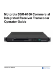
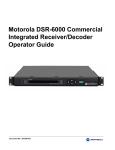
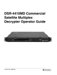
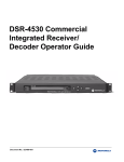
1
Paul, Discovery is suggesting that we add some language to the manual about setting up GigE output for multicast and unicast addresses. In their labs they had a difficult time setting up GigE out because the device they were connecting to didn't provide an ARP response. Jeff Paul, we need to add Web GUI info about transcoding in appliance mode and how to understand the possible output bandwith limitations. Motorola DSR-6400 Series Satellite Multiplex Receiver/ Transcoder Operator Guide RELAY 1 DSR-6400 RELAY 2 RELAY 3 ALARM Document No.: 583611-001 AUTHORIZED BYPASS MESSAGE SIGNAL DOWNLOAD WARNING The unauthorized modification of any unit and the sale and use of any such unit is prohibited by law. Any such modification or alteration of this product or any unauthorized reception of television programming could subject the user and seller and party modifying the unit to fines, imprisonment, and civil damages. NOTE: This equipment has been tested and found to comply with the limits for a Class A digital device, pursuant to Part 15 of the FCC Rules. These limits are designed to provide reasonable protection against harmful interference when the equipment is operated in a commercial environment. This equipment generates, uses and can radiate radio frequency energy and, if not installed and used in accordance with the instruction manual, may cause harmful, interference to radio communications. Operation of this equipment in a residential area is likely to cause harmful interference in which case the user will be required to correct the interference at his own expense. This digital apparatus does not exceed the Class A limits of radio noise emissions from digital apparatus set out in the Radio Interference Regulations of the Canadian Department of Communications. OPERATION PRECAUTIONS WARNING: TO PREVENT FIRE OR SHOCK HAZARD, DO NOT EXPOSE THIS EQUIPMENT TO RAIN OR MOISTURE. The lightning flash with the arrowhead symbol, within an equilateral triangle, is intended to alert the user to the presence of un-insulated “dangerous voltage” within the product’s enclosure that may be of sufficient magnitude to constitute a risk of electric shock to persons. The exclamation point within an equilateral triangle is intended to alert the user to the presence of important operating and maintenance (servicing) instructions in the literature accompanying the product. CAUTION Repairs and Assistance For assistance on return or repair see "Product Support" on page 79. Note to CATV System Installer This reminder is provided to call the CATV system installer’s attention to Article 820-40 of the National Electric Code (NEC) that provides guidelines for proper grounding and, in particular, specifies that the cable ground shall be connected to the grounding system of the building, as close to the point of cable entry as practical. Warning To prevent electrical shock, do not use the unit electrical power plug (polarized) with an extension cord, receptacle, or other outlet unless the blades can be fully inserted to prevent blade exposure. The mains disconnect device is the appliance plug and it shall remain readily accessible and operable. The lithium battery is not field-replaceable for the life of the product. General Instrument Corporation doing business as Motorola Mobility, Inc. 6450 Sequence Dr. San Diego, CA 92121 DOCUMENT No: 583611-001 REV B, 2/2/12 2 RISK OF ELECTRIC SHOCK CAUTION: TO REDUCE THE RISK OF ELECTRIC SHOCK, DO NOT REMOVE COVER (OR BACK). NO USER-SERVICEABLE PARTS INSIDE. REFER SERVICING TO QUALIFIED SERVICE PERSONNEL. ATTENTION This commercial unit is intended for the decoding of DigiCipher® II television signals for commercial use. Possession of this device does not enable or entitle the possessor to receive DigiCipher II television signals. Contact program providers to obtain appropriate authorizations. MOTOROLA and the Stylized M Logo are trademarks or registered trademarks of Motorola Trademark Holdings, LLC. All other trademarks are the property of their respective owners. Dolby Digital is a registered trademark of Dolby Laboratories. Dolby Digital is manufactured under license from Dolby Laboratories. © 2012 Motorola Mobility, Inc. All rights reserved. Important Safety Instructions • Read these instructions. • Unplug this apparatus during lightning storms or when unused for long periods of time. • Keep these instructions. • • Heed all warnings. • Follow all instructions. • Do not use this apparatus near water. • Clean only with dry cloth. • Do not block any ventilation openings. Install in accordance with the manufacturer’s instructions. Refer all servicing to qualified service personnel. Servicing is required when the apparatus has been damaged in any way, such as when the power-supply cord or plug is damaged, liquid has been spilled, or objects have fallen into the apparatus, the apparatus has been exposed to rain or moisture, does not operate normally, or has been dropped. • • Do not install near any heat sources such as radiators, heat registers, stoves, or other apparatus (including amplifiers) that produce heat. Do not defeat the safety purpose of the polarized or grounding-type plug. A polarized plug has two blades with one wider than the other. A grounding-type plug has two blades and a third grounding prong. The wide blade or the third prong is provided for your safety. If the provided plug does not fit into your outlet, consult an electrician for replacement of the obsolete outlet. • Protect the power cord from being walked on or pinched, particularly at plugs, convenience receptacles, and the point where they exit from the apparatus. • Use only attachments and accessories specified by the manufacturer. DSR-6400 Series Damage Requiring Service Unplug this equipment from the power source, and contact a qualified service provider if any of the following situations occurs: • If the power supply cord or plug is damaged. • If liquid or objects have fallen into the unit. • If the unit became wet from rain or water. • If the unit was dropped or damaged. • If the unit’s performance changes. Service Do not try to service this product yourself. If you open or remove the cover, you may be exposed to dangerous voltage or other hazards and may void the unit’s warranty. Contact a qualified service provider for all service. 3 ADVERTENCIA La modificación no autorizada de cualquier unidad, y la venta y el uso del mismo está prohibida por ley. Cualquier modificación o alteración de este producto o cualquier recepción no autorizada de programación de televisión puede someter al usuario y al vendedor, y a la parte que modifica la unidad a multas, prisión y daños civiles. NOTA: Este equipo se ha probado y se ha demostrado que cumple con los límites para un dispositivo digital clase A, según la parte 15 de las normas de la FCC. Estos límites están diseñados para ofrecer protección adecuada contra interferencia dañina cuando el equipo se utiliza en un entorno comercial. Este equipo genera, usa y puede irradiar energía de radiofrecuencia y, si no se instala y usa de acuerdo con el manual de instrucciones, puede causar interferencia dañina a las comunicaciones por radio. Es posible que el funcionamiento de este equipo en un área residencial cause interferencia dañina, en cuyo caso el usuario deberá corregir la interferencia y asumir el costo correspondiente. Este aparato digital no supera los límites de la clase A de emisiones de ruido de radio del aparato digital establecido en las Normas de interferencia de radio del Departamento canadiense de comunicaciones. PRECAUCIONES DE OPERACIÓN ADVERTENCIA: PARA EVITAR RIESGOS DE INCENDIOS O DESCARGA ELÉCTRICA, NO EXPONGA ESTE EQUIPO A LA LLUVIA O LA HUMEDAD. El símbolo del rayo con cabeza de flecha, dentro de un triángulo equilátero, está diseñado para alertar al usuario la presencia de "voltaje peligroso" sin aislamiento dentro del perímetro del producto que puede tener la magnitud suficiente para ser un riesgo de descarga eléctrica para las personas. El signo de exclamación dentro de un triángulo equilátero está diseñado para alertar al usuario la presencia de importantes instrucciones de funcionamiento y mantenimiento (servicio) en la literatura que acompaña al producto. PRECAUCIÓN RIESGO DE DESCARGA ELÉCTRICA. NO ABRIR. Reparación y asistencia Para recibir ayuda sobre devolución o reparación, consulte “Product Support” en la página 79. Nota para el instalador del sistema CATV Este recordatorio es para que el instalador del sistema CATV considere el Artículo 820-40 del Código eléctrico nacional (NEC) que entrega pautas para una correcta conexión a tierra y, en especial, especifica que la conexión a tierra del cable debe conectarse al sistema de conexión a tierra del edificio, lo más cerca posible del punto de entrada del cable. Advertencia Para evitar descargas eléctricas, no use el enchufe eléctrico de la unidad (polarizado) con un cable de extensión, receptáculo u otra salida a menos que las aspas queden completamente insertadas para evitar la exposición de las aspas. El dispositivo de desconexión de la red de suministro es el enchufe del aparato y debe ser de fácil acceso y estar en funcionamiento. La batería de litio no se reemplaza en la instalación para mantener la vida útil del producto. General Instrument Corporation comercializa como Motorola Mobility, Inc. 6450 Sequence Dr. San Diego, CA 92121 N°. DE DOCUMENTO: 583611-001 REV B, 2/2/12 4 PRECAUCIÓN: PARA REDUCIR EL RIESGO DE DESCARGA ELÉCTRICA, NO RETIRE LA CUBIERTA (O LA TAPA). EN EL INTERIOR NO H AY PIEZAS QUE SEAN PARA USO DEL USUARIO. SOLICITE ASISTENCIA TÉCNICA AL PERSONAL DE SERVICIO CALIFICADO. ATENCIÓN Esta unidad comercial está diseñada para decodificar señales de televisión DigiCipher® II para uso comercial. La posesión de este dispositivo no permite ni autoriza al dueño a recibir señales de televisión DigiCipher II. Comuníquese con los proveedores de programa para obtener las autorizaciones correspondientes. MOTOROLA y el logotipo de la M estilizada son marcas comerciales o marcas comerciales registradas de Marcas Participantes de Motorola LLC. Todas las demás marcas comerciales son propiedad de sus respectivos dueños. Dolby Digital es una marca comercial registrada de Dolby Laboratories. Dolby Digital está fabricado bajo la licencia de Dolby Laboratories. © 2012 Motorola Mobility, Inc. Todos los derechos reservados. Instrucciones de seguridad importantes • Lea estas instrucciones. • Guarde estas instrucciones. • Considere todas las instrucciones. • Siga todas las instrucciones. • No use este aparato cerca del agua. • Limpie sólo con un paño seco. • No bloquee las aberturas de ventilación. Instale siguiendo las instrucciones del fabricante. • No instale cerca de fuentes de calor como radiadores, rejillas de aire caliente, cocinas u otros aparatos que produzcan calor (incluidos amplificadores). • No impida el propósito de seguridad del enchufe polarizado o con conexión a tierra. Un enchufe polarizado tiene dos aspas, una más ancha que la otra. Un enchufe de conexión a tierra tiene dos aspas y una tercera punta con conexión a tierra. El aspa ancha o la tercera punta está diseñada para su seguridad. Si el enchufe incluido no se ajusta a la salida, pida al electricista el repuesto de la salida obsoleta. • Todos los servicios de mantenimiento deben realizarlos personal calificado. El servicio de mantenimiento se requiere cuando el aparato tiene algún daño, por ejemplo cuando el cable de alimentación o enchufe está dañado, se ha derramado líquido o el aparato ha sido golpeado por otros objetos, cuando se ha expuesto a lluvia o humedad, no funciona normalmente o se ha caído. DSR-6400 Series • Proteja el cable de alimentación para evitar pisarlo o que quede apretado, especialmente en los enchufes y tomas de corriente, y revise el punto de salida del aparato. • Use exclusivamente los accesorios especificados por el fabricante. • Desconecte el aparato durante tormentas eléctricas o cuando no se use durante un tiempo prolongado. Daños que requieren servicio de mantenimiento Desenchufe este equipo de la fuente de alimentación y comuníquese con un proveedor de servicio calificado si se presenta alguna de las siguientes situaciones: • Si el cable de alimentación o enchufe está dañado. • Si sobre la unidad ha caído líquido o algún objeto. • Si la unidad se moja por la lluvia o el agua. • Si la unidad se golpeó o dañó. • Si se altera el funcionamiento de la unidad. Servicio No intente reparar este producto usted mismo. Si abre o retira la cubierta, es posible que se exponga a voltaje peligroso u otros daños, y anule la garantía de la unidad. Para todo tipo de mantenimiento, comuníquese con un proveedor de servicio calificado. 5 Table of Contents Chapter 1 Chapter 2 Chapter 3 Introducing the DSR-6400 Series...................................................................................................... Key Features ................................................................................................................................ Model and Transcoding Capacity................................................................................................. PID Mapping................................................................................................................................. Processor / Back Panel Associations........................................................................................... Connecting the DSR-6400 Series Unit.............................................................................................. Unpacking and Connecting the DSR-6400 Series Unit................................................................ Unpacking .................................................................................................................................... Rack Mounting Guidelines ........................................................................................................... Mechanical Loading .............................................................................................................. Ambient Temperature ........................................................................................................... Circuit Overloading ............................................................................................................... Earth Ground ........................................................................................................................ Battery Replacement ............................................................................................................ Connecting the DSR-6400 Series ................................................................................................ Remote Operation ........................................................................................................................ Operating the DSR-6400 Series........................................................................................................ Using the Front Panel................................................................................................................... Navigating the Menus................................................................................................................... How to Use the Menus ................................................................................................................. About Menu........................................................................................................................... Main Menu ............................................................................................................................ Overview of The LCD Panel Menu Tree ...................................................................................... Installation Menus ........................................................................................................................ Manual Tune Menu ...................................................................................................................... ASI Input ...................................................................................................................................... Input Field ............................................................................................................................. GigE Input .................................................................................................................................... Input Field ............................................................................................................................. GigE Input IP Addr Field ....................................................................................................... RF Input ....................................................................................................................................... Input Field ............................................................................................................................. Mode Field ............................................................................................................................ Xpndr Field............................................................................................................................ LFreq Field............................................................................................................................ Modulation Menu.......................................................................................................................... Mode Field ............................................................................................................................ Symbol / Code / Format Fields ............................................................................................. DSR-6400 Series 13 13 14 15 16 17 17 18 19 19 19 19 19 19 20 21 23 24 25 26 26 26 27 30 30 31 31 31 31 32 32 32 33 33 34 35 35 35 7 1 Port Menu..................................................................................................................................... 36 ID Field.................................................................................................................................. 36 Mode Field ............................................................................................................................ 36 Sat Field ................................................................................................................................ 37 Polar Field ............................................................................................................................. 37 Port Config Menu ......................................................................................................................... 37 Port 1 Power Field................................................................................................................. 37 Audio1 and Audio2 Menus ........................................................................................................... 38 AudioMix Field....................................................................................................................... 38 DialNorm/Compress Field ..................................................................................................... 39 Audio1 and Audio2 Gain Menus................................................................................................... 40 Mode Field ............................................................................................................................ 40 Left and Right Fields ............................................................................................................. 40 Alarm Menu .................................................................................................................................. 41 Trigger Field .......................................................................................................................... 41 Test Field .............................................................................................................................. 41 4th Relay Menu (DSR-6404 only) ................................................................................................ 42 Config Field ........................................................................................................................... 42 ASI Output Menu.......................................................................................................................... 42 Enable Field .......................................................................................................................... 42 ASI Output Rate Menu ................................................................................................................. 43 ASI1 Field ............................................................................................................................. 43 ASI2 Field ............................................................................................................................. 43 Reset Menu .................................................................................................................................. 44 Reset Type Field ................................................................................................................... 44 Factory Defaults Option ........................................................................................................ 44 Power Cycle Option .............................................................................................................. 44 Code Select Field.................................................................................................................. 45 Core Menu.................................................................................................................................... 47 Contrast Field........................................................................................................................ 47 Video Out Menu ........................................................................................................................... 47 525 Field ............................................................................................................................... 48 625 Field ............................................................................................................................... 48 Firmware Menu ............................................................................................................................ 48 Boot:FPGA:High Field........................................................................................................... 48 Upgrade Field........................................................................................................................ 49 Download Menu ........................................................................................................................... 49 File Field................................................................................................................................ 49 Current Field ......................................................................................................................... 49 Rcvd Field ............................................................................................................................. 49 Total Field ............................................................................................................................. 49 DR Menu (Acquisition Recovery) ................................................................................................. 50 MODE Field........................................................................................................................... 50 8 VCT (Virtual Channel Table) Field ........................................................................................ VCN (Virtual Channel Number) Field .................................................................................... PORT Field ........................................................................................................................... Channel Menus ............................................................................................................................ PR Field (DSR-6402, DSR-6403, and DSR-6404 only) ........................................................ VCT Field .............................................................................................................................. CHNL Field ........................................................................................................................... Xpndr Field............................................................................................................................ MPEG SELECT Menu.................................................................................................................. PR Field (DSR-6402, DSR-6403, and DSR-6404 only) ........................................................ Program Field ....................................................................................................................... AUD1LANG and AUD2LANG Menus........................................................................................... Dspl Field .............................................................................................................................. Left and Right Fields ............................................................................................................. InputMode Field .................................................................................................................... Text Lang Menu ........................................................................................................................... Display Field ......................................................................................................................... Subtitle Field ......................................................................................................................... IP Menus ...................................................................................................................................... 10/100 MAC Address Menu ......................................................................................................... 10/100 DHCP Menu ..................................................................................................................... DHCP Field ........................................................................................................................... Unit Name Field .................................................................................................................... 10/100 IP Address Menu.............................................................................................................. 10/100 Subnet Mask Menu .......................................................................................................... 10/100 Default Gateway Menu..................................................................................................... Port GigE MAC Address Menu..................................................................................................... GigE IP Address Menu................................................................................................................. GigE Subnet Mask Menu ............................................................................................................. GigE Default Gateway Menu........................................................................................................ GigE TS Mode Menu.................................................................................................................... TS Mode Field....................................................................................................................... DSMCC Field ........................................................................................................................ GigE Output Transport Streams ........................................................................................... GigE Xcoded Dest Addr Menu ..................................................................................................... Xcoded Dest Addr Field ........................................................................................................ Port Field............................................................................................................................... GigE PassThru Dest Addr Menu .................................................................................................. PassThru Dest Addr Field..................................................................................................... Port Field............................................................................................................................... Status Display Menus................................................................................................................... Status0 Menu ............................................................................................................................... Health Field........................................................................................................................... Alarm Trigger Field ............................................................................................................... DSR-6400 Series 50 50 50 51 51 51 51 53 53 53 53 54 55 55 56 56 56 57 57 57 58 58 58 58 59 59 59 60 60 60 61 61 61 61 62 62 62 62 62 62 63 63 63 63 9 1 Status1 Menu ............................................................................................................................... 64 FrontPanel Field.................................................................................................................... 64 Input Type Field .................................................................................................................... 64 Status2 Menu ............................................................................................................................... 65 Source Field .......................................................................................................................... 65 Channel Field ........................................................................................................................ 65 Quality Field .......................................................................................................................... 65 Status3 Menu ............................................................................................................................... 65 Status4 Menu ............................................................................................................................... 66 Sat Field ................................................................................................................................ 66 Freq Field .............................................................................................................................. 66 Symb Field ............................................................................................................................ 66 Code Field............................................................................................................................. 66 Format Field .......................................................................................................................... 66 Status5 Menu ............................................................................................................................... 66 Sync Field ............................................................................................................................. 67 Eb/No Field ........................................................................................................................... 67 Authorize State Field............................................................................................................. 67 Status6 Menu ............................................................................................................................... 68 Memory Field ........................................................................................................................ 68 Flash Field............................................................................................................................. 68 Hard Drive Field .................................................................................................................... 68 Status7(SD) Menu........................................................................................................................ 69 PR Field (DSR-6402, DSR-6403, and DSR-6404 only) ........................................................ 69 Vido Frmt Field and Resolution Field .................................................................................... 69 BitRt Field.............................................................................................................................. 69 Status8(SD) Menu........................................................................................................................ 70 PR Field (DSR-6402, DSR-6403, and DSR-6404 only) ........................................................ 70 Aud Field ............................................................................................................................... 70 Format Field .......................................................................................................................... 70 Mode Field ............................................................................................................................ 70 BitR Field............................................................................................................................... 70 Status9(HD) Menu........................................................................................................................ 71 PR Field (DSR-6402, DSR-6403, and DSR-6404 only) ........................................................ 71 Vido Fmt Field ....................................................................................................................... 71 Resolutn Field ....................................................................................................................... 71 BitRt Field.............................................................................................................................. 71 Status10(HD) Menu...................................................................................................................... 71 PR Field (DSR-6402, DSR-6403, and DSR-6404 only) ........................................................ 72 Aud Field ............................................................................................................................... 72 Format Field .......................................................................................................................... 72 Mode Field ............................................................................................................................ 72 BitR Field............................................................................................................................... 72 10 Chapter 4 Chapter 5 Chapter 6 Chapter 7 Chapter 8 Status11 Menu ............................................................................................................................. Addr Field.............................................................................................................................. Link Field............................................................................................................................... Status12 Menu ............................................................................................................................. Pointer and Quantity Fields................................................................................................... Timestamp and Message Fields ........................................................................................... Status13 Menu ............................................................................................................................. Pointer and Quantity Fields................................................................................................... Timestamp and Message Fields ........................................................................................... Diagnostic Menus......................................................................................................................... Menus Field .......................................................................................................................... Clear Cntrs Field ................................................................................................................... PR Field (DSR-6402, DSR-6403, and DSR-6404 only) ........................................................ Unit Address Menu....................................................................................................................... TV Pass Card Menu ..................................................................................................................... Audio Test Signal Menu ............................................................................................................... L1/R1 and L2/R2 Fields ........................................................................................................ Video Test Signal Menu ............................................................................................................... Pattern Field.......................................................................................................................... Ad Insertion Test Menu ................................................................................................................ Cue Tone Field ..................................................................................................................... Relay Field ............................................................................................................................ Product Support ................................................................................................................................ If You Need Help .......................................................................................................................... Calling for Repairs........................................................................................................................ Downlink/L-Band Frequency Conversion Tables .............................................................................. Language Abbreviations ................................................................................................................... Diagnostics........................................................................................................................................ Introduction .................................................................................................................................. Viewing the Fast Fact Diagnostic Screens................................................................................... Fast Facts 1 .......................................................................................................................... Fast Facts 2 .......................................................................................................................... Fast Facts 3 .......................................................................................................................... Fast Facts 4 (Audio 1 and 2)................................................................................................. Fast Facts 5 (10/100 Network).............................................................................................. Fast Facts 5 (Gigabit Ethernet)............................................................................................. Fast Facts 7 (Decoder Address) ........................................................................................... Fast Facts 8 (Inbox) .............................................................................................................. Fast Facts 9 (Archive)........................................................................................................... DSR-6400 Series Specifications ....................................................................................................... DSR-6400 Series 72 72 72 73 73 74 74 74 74 75 75 75 75 76 76 76 77 77 77 78 78 78 79 79 80 81 83 85 85 86 87 89 90 92 93 94 95 96 97 99 11 1 Introducing the DSR-6400 Series The Motorola DSR-6400 Series products are commercial Satellite Receiver/Transcoders, designed for broadcasters and headend operators for receiving digital satellite services. The DSR-6400 Series units will process both high-definition and standard-definition video services. After the DSR-6400 Series units are properly installed and configured, they will be ready to receive authorization and control information from the satellite signal source provider. Key Features • Eight RF inputs • DC-II QPSK and DVB-S2 demodulation • DigiCipher-II security • GigE and ASI inputs and outputs (Digital HD and SD output) • Two analog composite (SD) video output ports. The second (OSD video) is for diagnostic use. • VBI reinsertion for Closed Captioning • Two stereo pair audio output • DTMF output • Up to four Form-C relays for ad insertion support • One Form-C relay for fault alarm indication • Uplink controlled retunes • Memory: Configuration is saved in nonvolatile memory. • A two-line, 40-character front panel with a Liquid Crystal Display (LCD) DSR-6400 Series 13 1 • MPEG-2 HD and/or SD ASI and GigE outputs • Web Server GUI for remote operation • Advanced audio processing - Supports pass-through and decoding/decompression of Dolby AC-3 and pass-through of the Dolby E audio compression algorithm • Message Mailbox - Supports text message delivery from the uplink for display on the IRD’s front panel. • DPI support - Digital (SCTE-35) ad-splicing message support in both broadcast and unitaddressable formats • DTMF cue tone and Form-C contact closure relay terminals for each processed service • Scalable service transcoding - shown in Figure 1-1. Model and Transcoding Capacity The DSR-6400 Series includes a range of products differentiated by the number of services the units are able to simultaneously receive and transcode. The DSR-6401 transcodes one service, the DSR6402 transcodes two, the DSR-6403 transcodes three, and the DSR-6404 transcodes four services. For setup purposes, the DSR-6400 Series introduces the concept of "processor" or PR in the user interface. A PR number in the user interface identifies the individual service processor path and the unique configuration settings assigned to (or the status information that pertains to) each programmer service being received in a multi-service unit. Each path transcodes a single service according to its own unique configuration settings. The DSR-6400 Series provides service transcoding that processes up to four MPEG-4 HD input services into four MPEG-2 HD/SD output service pairs (up to eight total services). Figure 1-1 shows how service capacity varies by model. DSR-6400 Series Models DSR-6401 (one processor) DSR-6402 (two processors) DSR-6403 (three processors) DSR-6404 (four processors) Input Resolution Service 1 2 3 4 SD HD SD HD SD HD SD HD Bit Rate CBR VBR or CBR CBR VBR or CBR CBR VBR or CBR CBR VBR or CBR MPEG Program ID 1 2 3 4 5 6 7 8 Figure 1-1: DSR-6400 Series Transcoding 14 Note: For example, on a DSR-6404, if all SD services are disabled in the transcoded output, then programs 1, 3, 5, and 7 will not be output. PID Mapping The DSR-6400 Series uses a PID mapping scheme for the output services for ASI and GIGE output ports. The following two tables show each of the individual service components and their assigned PID values on each MPEG program. These PID values affect the output ports: ASI OUT 1, ASI OUT 2, and GIGE, as shown below. For multiple instances of the same component type, the unit increments the PID value by one. PID Assignments: ASI OUT 1 Port MPEG Program Processor Path 1 1 2 2 3 3 4 4 Number Format PMT Video Audio1 Audio2 DPI DSMCC Subtitle Decimal 256 272 288 289 304 320 336 Hex 100 110 120 121 130 140 150 Decimal 512 528 544 545 560 576 592 Hex 200 210 220 221 230 240 250 Decimal 768 784 800 801 816 832 848 Hex 300 310 320 321 330 340 350 1024 1040 1056 1057 1072 1088 1104 400 410 420 421 430 440 450 Decimal Hex Note: The GIGE port carries the same PID mapping information as the two ASI OUT ports. ASI IN ASI OUT 1 ASI OUT 2 VIDEO OUT OSD VIDEO OUT GIGE 10 / 100 ETHERNET PID Assignments: ASI OUT 2 Port Program/ Transcoded Resolution From 1 (SD) 2 (HD) 3 (SD) 4 (HD) 5 (SD) 6 (HD) 7 (SD) 8 (HD) ASI1 Program 1 ASI1 Program 2 Number Format PMT Video Audio1 Audio2 DPI DSMCC Subtitle Decimal 256 272 288 289 304 320 336 Hex 100 110 120 121 130 140 150 Decimal 512 528 544 545 560 576 592 Hex 200 210 220 221 230 240 250 Decimal 768 784 800 801 816 832 848 Hex 300 310 320 321 330 340 350 1024 1040 1056 1057 1072 1088 1104 400 410 420 421 430 440 450 1280 1296 1312 1313 1328 1344 1360 500 510 520 521 530 540 550 1536 1552 1568 1569 1584 1600 1616 600 610 620 621 630 640 650 1792 1808 1824 1825 1840 1856 1872 700 710 720 721 730 740 750 2048 2064 2080 2081 2096 2112 2128 800 810 820 821 830 840 850 Decimal Hex Decimal ASI1 Program 3 Hex Decimal Hex Decimal ASI1 Program 4 DSR-6400 Series Hex Decimal Hex 15 1 Processor / Back Panel Associations Figure 1-2 shows how Processor numbers (PR) coincide with the Cue Tone ports and Relay ports on the back panel. For example, a DSR-6402 has two processors. The two services use cue tones Q1 (for Processor 1) and Q2 (for Processor 2). To execute Ad insertions, the two processors also use Relay port 1 (for Processor 1) and Relay port 2 port (for Processor 2). Figure 1-2 also shows how all PR fields are linked within the menu system. PRIMARY AUDIO RELAY 1 ALARM Q1+ Q1- G Q2+ Q2- L+ L- G R+ R- NO CM NC G NO CM NC Model Available PR Fields Relay Ports Cue Tone Ports DSR-6401 (none) 1, 2, 3 (See Note.) Q1 DSR-6402 1, 2 1, 2 Q1, Q2 DSR-6403 1, 2, 3 1, 2, 3 Q1, Q2, Q3 DSR-6404 1, 2, 3, 4 1, 2, 3, [4] Q1, Q2, Q3, Q4 Q3+ Q3- G Q4+ Q4- L+ L- G R+ R- NO CM NC G NO CM NC SECONDARY AUDIO RELAY 2 RELAY 3 If a fourth relay is necessary on a DSR-6404, see "4th Relay Menu (DSR-6404 only)" on page 42. CHANNEL PR VCT CHNL Xpndr 12 00000 MPEG SELECT PR E 0000 (MPEG mode) Program 2 1 E 00000(Not in map) STATUS7 SD PR Vido Frmt Resolutn BitRt 12 E STATUS8 SD E MPEG-2 720x480 6.0M PR Aud Format Mode BitR 2 1 --- 0 PSTHRU --- STATUS9 HD PR Vido Fmt Resolutn E 12 MPEG-2 12 DIAG E Menus Fact 1 0 18.0M PSTHRU --- Clear Cntrs No The other models have one dedicated relay for each processor (supporting only one ad insertion choice per processor). For more ad insertion choices, use Cue Tones instead. BitRt 1280x720 STATUS10 HD PR Aud Format Mode E Note: The DSR-6401 has one processor and does not display the PR field on any menu. It also uses three Relay ports (supporting up to three possible ad insertion choices). BitR --- PR 12 Changing any one of the PR fields will change all PR fields throughout the entire menu system. Figure 1-2: Processor / Back Panel Associations 16 2 Connecting the DSR-6400 Series Unit Unpacking and Connecting the DSR-6400 Series Unit Cable connections, described in this chapter, are made to the back panel of the unit. Earth Ground Terminals Relay/Alarm Fan Unit Primary Audio Out L-Band RF Input Ports 1 - 8 Fan Unit RF IN 1 TVPass® Card 2 3 4 ASI IN CF TYPE 1 10 / 100 GIGE ETHERNET TV Pass Card Ethernet Port GigE Port ASI In 5 ASI OUT 1 ASI OUT 2 PRIMARY AUDIO RELAY 1 ALARM Q1+ Q1- G Q2+ Q2- L+ L- G R+ R- NO CM NC G NO CM NC 6 7 8 VIDEO OUT OSD VIDEO OUT RELAY CONTACT RATING 1A Q3+ Q3- G Q4+ Q4- L+ L- G R+ R- NO CM NC G NO CM NC 30 VDC SECONDARY AUDIO RELAY 2 RELAY 3 CAUTION: DISCONNECT POWER CORD BEFORE SERVICING 100-240 VAC, 50 / 60 Hz ASI Out OSD Video Out Video Out Power Connector Secondary Audio Out Figure 2-1: DSR-6400 Series Back Panel (Overview) DSR-6400 Series 17 2 Note: Additional audio and data connectors may be ordered through Phoenix Contact part numbers 1881354 / 1881370. PRIMARY AUDIO RELAY 1 ALARM Q1+ Q1- G Q2+ Q2- L+ L- G R+ R- NO CM NC G NO CM NC CAUTION: When connecting any of the eight RF IN ports, the RF-IN Antenna cable should only be connected while the unit is properly grounded and the shield of the coaxial cable should be earthed in accordance with Article 820.93 of the NEC, ANSI/ NFPA 70:2005 or equivalent. RELAY CONTACT RATING 1A Q3+ Q3- G Q4+ Q4- L+ L- G R+ R- NO CM NC G NO CM NC 30 VDC SECONDARY AUDIO RELAY 2 RELAY 3 CAUTION: DISCONNECT POWER CORD BEFORE SERVICING 100-240 VAC, 50 / 60 Hz RF IN 1 2 3 4 ASI IN 5 ASI OUT 1 ASI OUT 2 6 7 8 VIDEO OUT OSD VIDEO OUT 10 / 100 GIGE ETHERNET Figure 2-2: DSR-6400 Series Back Panel (Detailed) Unpacking The shipping carton contains the DSR-6400 Series unit, quick disconnect terminals, power cord, mounting brackets, mounting ears, rails, and this Operator Guide. 18 Rack Mounting Guidelines The DSR-6400 Series unit, with the supplied mounting brackets is designed for installation in an EIA standard 19-inch (480 mm) equipment rack. Place each unit in a stable and level position within the rack and ensure that all front enclosure screws are tightened to 14 inlbs. If multiple DSR-6400 Series units are installed in a rack assembly, the operator may choose to have a certification agency evaluate the condition of the rack. Mechanical Loading The mounting rack location should be secure and level to avoid hazardous instability to the equipment due to uneven loading or weight distribution within the rack. Ambient Temperature When installing a DSR-6400 Series unit within a closed or multi-unit rack, the ambient temperature may be greater than the ambient temperature within the room. Therefore, verify that the amount of air flow required for safe operation is not compromised (maximum temperature for the equipment is 40° C). Consideration should be given to the maximum rated ambient temperature for the unit’s location when planning for cooling and air circulation. To evacuate the unit’s warm air output from within the mounting rack, Motorola Mobility recommends the use of a fan on top of the rack. Circuit Overloading If the unit is connected to a power strip, rather than a branch circuit’s direct connection, use special care to ensure that the unit is properly connected. Always consider the affect that overloading circuits might have on over-current protection and supply wiring. To ensure that circuits are not overloaded, read the DSR-6400 Series UL regulatory power label on top of the unit. Check all equipment power/amperage ratings to ensure the mounting rack power rating is not exceeded. Earth Ground Reliable earthing of rack-mounted equipment should be maintained. Particular attention should be given to supply connections other than direct connections to the branch circuit (e.g. use of power strips). The RF-IN antenna cable should only be connected while the unit is properly grounded. The shield of the coaxial cable should be earthed in YP accordance with Article 820.93 of the NEC (National Electrical Code), ANSI/NFPA 70:2005, or equivalent. Battery Replacement Do not replace the lithium battery used in the unit. Instead, return the unit to a Motorola Mobility authorized service center for replacement with the same or equivalent type battery as recommended by the manufacturer. DSR-6400 Series 19 2 Connecting the DSR-6400 Series To connect a DSR-6400 Series to the GigE signal, see "GigE Input" on page 31. To connect a DSR-6400 Series to an ASI signal, see "ASI Input" on page 31. To connect a DSR-6400 Series to an RF signal: 1. Determine which satellite, transponder, Virtual Channel Table (VCT) number, and Virtual Channel is to be used. Contact the programmer for this system information so that the desired services can be received. 2. Connect the desired L-Band (satellite antenna LNB or LNB signal splitter) source cable to RF Input Port 1 through 8, as directed by the programmer. Note: LNB power can be enabled for RF Input Port 1. 3. To view video and On-Screen Diagnostics (OSD) during installation, connect the OSD Video Output on the back panel to a 75-ohm video monitor or television with composite video input (standard definition). Note: The unit generates time-specific ad insertion cue tones and relays. The programmer can include these messages in the encoded signal. 4. If cue tones are needed and made available, connect the differential Cue Tone+, Cue Tone-, and Ground terminals on the unit to the 600-ohm device receiving the tones. Note: The unit provides an alarm relay that can be used to signal an alarm condition. To indicate an alarm, the unit provides a short-circuit electrical connection between the NC and CM terminals and an open-circuit electrical connection between the NO and CM terminals. With this configuration, the unit is able to signal an alarm, even for the loss of AC power. 20 5. Plug the unit into a power source. Verify that the LCD screen is lit. 6. Proceed with the installation using the front panel menus. 7. For details on web server GUI, see "Remote Operation" on page 21. Remote Operation The DSR-6400 Series decoder can be operated remotely from a web browser. When the decoder is contacted via an HTTP session from a computer, the decoder’s web server responds to the HTTP session with a login dialog box that requires the user to login with user name and password. Once the login is successful, the decoder’s web server then presents the unit’s home page to the browser. Some of the IRD configuration settings and control inputs that are accessible through HTTP include: • Virtual channel and audio language selection • Status and device information (e.g., signal strength, alarms, unit address) • Soft reset (AC power cycle) • Settings for acquiring a satellite signal (e.g., transponder frequency, input port) • Video and audio output customizations • Alarm triggers • ASI and Ethernet output customizations • Complete Transcoder configuration (Read-only when set by uplink programmer) To configure the DSR-6400 Series unit for remote operation 1. Contact your network administrator for the IP Subnet Mask address, unique IP address, and default gateway address to assign to this decoder. Caution: By default, all DSR-6400 series units have the same IP address. To use the unit’s remote operation, each unit on the subnet must be assigned a unique IP address. Failure to assign a unique IP address to each unit on the subnet will result in loss of connectivity. 2. To configure the decoder, use the decoder’s arrow buttons on the front panel to perform the following procedures: • 10/100 IP Address Menu, page 58 • 10/100 Subnet Mask Menu, page 59 • 10/100 Default Gateway Menu, page 59 3. Use an RJ-45 cable to connect the decoder’s Ethernet 10/100 port to the subnet that will be used to operate the decoder remotely. DSR-6400 Series 21 2 To operate the DSR-6400 Series decoder remotely 1. Open a browser session, type the decoder’s unique IP address in the address bar, and press the ENTER key. For example, if the decoder is configured with IP address 10.11.23.60, then go to the browser, type: http://10.11.23.60 in the address bar, and press ENTER. 2. When the login dialog box appears (as shown below), enter the User name and Password and select OK. Note: The uplink programmer who authorizes the unit has the option to set the User Name and Password. If they authorize the unit without using this option, leave both fields blank and simply select OK to gain access to web-based remote operation. (Blank) is the default User Name and Password. 3. When the Home Page appears (as shown below), use the sidebar menu to access the decoder’s various settings and control features. 6401 22 . 3 Operating the DSR-6400 Series All operations described in this chapter require use of the front panel, as shown in Figure 3-1. DSR-6400 MESSAGE Relay Alarm LCD Screen Authorized Arrow Buttons Message Signal Download ENTER Button Figure 3-1: DSR-6400 Series Front Panel The following list describes the LEDs located on the left and right sides of the LCD screen. Relay Illuminates when relays are activated. Alarm Illuminates when the unit enters an alarm state. Authorized Illuminates when the unit is authorized by the service provider. Message Illuminates when the unit has a mailbox message from the uplink. Signal Illuminates when the unit is locked to a valid carrier. Download Blinks when a firmware download is in progress and illuminates solid when the unit has successfully received the firmware download and is waiting for activation by the programmer. DSR-6400 Series 23 3 Using the Front Panel The front panel LCD screen displays a series of menus that can be used to configure and control the system. The name of the current menu is always in the upper left corner of the screen for easy identification. • Beneath every menu name are symbols representing key presses that are possible from the current cursor position in the menu. Note that the available keypad moves may change during the navigation between menu fields. Menu Name E 24 Label Label Label Setting Setting Setting • The top row, to the right of the menu name, displays the name of each field available within that menu. These are called field labels and its setting is displayed directly below. • Beneath each label is the current setting for each field. • Some fields may be changed by the user and others are for display purposes only. Fields that can be changed have an arrow indicator ( ) just to the left of the field label. During left/right navigation, the cursor skips over the labels that cannot be changed. Navigating the Menus Even though the keypad options shown on the LCD screen may change for each menu and for each field, the control buttons basically do the same thing. The user may want to practice on a screen to become familiar with how the buttons work. Notice that: • Pressing the buttons while the cursor is blinking next to the menu name (far left corner), causes the cursor to scroll to another menu. • Pressing ENTER while the cursor is blinking next to the menu name (far left corner) causes the cursor to scroll to the Main, top-level menu. • Pressing the 4buttons while in the top line of the menu causes the cursor to move between field labels (or the menu name and a field label). • Pressing the 4 button at the rightmost field label causes the cursor to wrap to the left side of the screen (to the menu name). Likewise, pressing the button when the cursor is at the menu name causes the cursor to wrap to the rightmost field label. • When the cursor is blinking on a field label (top row), pressing ENTER causes the cursor to move below the label and enter into the field so the setting can be changed. • When the cursor is below the label, the displayed directional controls in the left corner show what symbol is left of the field, this buttons can be pressed to change the setting in that field. When the indicates the ability to select from the available values. Placing the blinking cursor on those arrows and press the buttons to reveal each of the available choices for that field, one at a time. To store changes in a field and move back up to the label line, press ENTER. • DSR-6400 Series 25 3 How to Use the Menus About Menu The front-panel LCD displays the About menu when the unit is initially plugged in or after a factory reset. This menu identifies the model (either DSR-6401, DSR-6402, DSR-6403, or DSR-6404) and the second line displays the DSR-6400 Series’s actual firmware version instead of 0xXXXXX, as shown below. MOTOROLA DSR-6400 Version 0xXXXXX This menu is displayed for 10 seconds, then the front-panel LCD displays the Main menu. Main Menu This menu is the top-level menu and can be accessed from any other menu by pressing ENTER while the cursor is blinking next to the menu name. This menu allows the user to select any one of the five main menu groups: Installation menus, Channel menus, IP menus, Status menus, and Diagnostic menus. DSR-640X E Install Channel IP Status Diag Note: In the above graphic, the X in DSR-640X designates the exact model (DSR-6401, DSR-6402, DSR-6403, or DSR-6404). The unit allows the user to scroll () only to menus that are in the same group. To scroll to a menu that is in a different menu group, return to the main top-level menu and select the desired menu group. To return to the main top-level menu from any menu, place the cursor in the upper-left corner and press ENTER. 26 Overview of The LCD Panel Menu Tree Pressing ENTER when the cursor is on a menu name causes the cursor to return to the main, top level menu. The charts on the following pages show the menus organized into five main groups: Installation menus, Channel selection menus, IP menus, Status menus, and Diagnostic menus. INSTALLATION MENUS MANUAL TUNE Input Mode Xpndr LFreq E Port 1 Xpndr 01 1430.00 MANUAL TUNE Input E MANUAL TUNE Input GigE In GigE Input E MODULATION E IP Address Port 239.001.001.001 00000 Mode DCII-AUTO MODULATION E MODULATION E Symbol DVBS2 30.000000 Mode Symbol DVB-MAN MODULATION Mode E PORT ID E 1 DCII-MAN Sym 19.51 Polar --- --- 4th RELAY E Stereo Stereo DSR-6400 Series Left Right +00 +00 Left Right +00 +00 Test Off Note: The Modulation, Port, and Port Config menus are only present when one of the RF ports is selected as the input within the Manual Tune menu. Config Alarm On Comb Port 1 Power DialNorm/Compress On-Moderate ASI1 ASI2 78 108 Reset Type Code Select No 0x333 active CORE E Code Format 3/4 E The 4th Relay menu is only present on a DSR-6404. The GigE Input menu is only present when GigE is selected as the input. Contrast 18 VIDEO OUT 525 625 E NTSC PAL-625 FIRMWARE Boot:FPGA:High E E DR Upgrade XXXXXX:XXXXXX:XXXXXX 000000 DOWNLOAD Off AUDIO2 AudioMix E Trigger Auto RESET Symbol Sat AUDIO1 AudioMix E ALARM E E 01.000000 Mode E Joint ASI OUTPUT RATE 01.000000 Auto PORT CONFIG Mode E E Mode Mode E Joint ASI OUTPUT Enable 8PSK-TC MODULATION Mode E AUDIO2 GAIN ASI In E AUDIO1 GAIN File 00 of 00 MODE E DISABLED VCT Current Rcvd Total 0000 VCN (00000) ---- 0000 0000 PORT NA DialNorm/Compress On-Moderate 27 3 Channel Selection Menus CHANNEL PR VCT E CHNL Xpndr 1 00000 MPEG SELECT PR E 1 AUD1LANG Dspl Left E All def AUD2LANG Dspl Left E All def 0000 (MPEG mode) Program 00000(Not in map) Right InputMode def --- Right InputMode def --- IP MENUS PORT 10/100 E PORT 10/100 E PORT 10/100 E PORT 10/100 E PORT 10/100 E PORT GigE E 28 MAC Address hh:hh:hh:hh:hh:hh DHCP Unit Name Disable DSR640X-XXXXX IP Address 192.168.000.100 Subnet Mask 255.255.255.000 Default Gateway 192.168.000.001 MAC Address hh:hh:hh:hh:hh:hh PORT GigE IP Address E PORT GigE 192.168.054.100 Subnet Mask E PORT GigE 255.255.255.000 Default Gateway E 192.168.054.002 PORT GigE TS Mode E Off PORT GigE Xcoded Dest Addr E 192.168.054.201 PORT GigE PassThru Dest Addr E 192.168.054.200 DSMCC Off Port 06100 Port 06000 Status Menus STATUS0 E STATUS1 Alarm Trigger Acq:Alarm Auto FrontPanel E Source E STATUS3 E E Quality ---- Sat Freq Symb Code Format --- 1430.00 11.71 5/6 STATUS5 E Sync Eb/No Tuning -2.0 STATUS6 720x480 E Comb Authorize State Undefined Service Memory Flash Hard Drive 8.0MB 450.4MB 14.9GB E STATUS11 E 6.0M PR Aud Format Mode BitR 1 --- 0 PSTHRU --- 1 MPEG-2 1280x720 STATUS10 HD PR Aud Format Mode Signal Quality E MPEG-2 STATUS9 HD PR Vido Fmt Resolutn --- |||||||||||||||||||||||....... STATUS4 1 STATUS8 SD L-Band Channel --- STATUS7 SD PR Vido Frmt Resolutn BitRt E Input Type Local-Control STATUS2 E Health 1 0 PSTHRU --- BitRt 18.0M BitR --- Addr Field Link Field ---------- Off STATUS12 MAIL: INBOX > 0/0 E STATUS13 MAIL: ARCHIVE > 0/0 E Diagnostic Menus DIAG E Menus UNIT ADDRESS E TV PASS CARD E PR Off 1 ddd-ddddd-ddddd-ddd Status Not Inserted AUDIO TEST SIGNAL L1/R1 E Off L2/R2 Off VIDEO TEST SIGNAL Pattern E AD INSERTION TEST E DSR-6400 Series Off Cue Tone Relay Off Off 29 3 Installation Menus The purpose of the installation menus is to configure the ports and choose settings that remain fixed over time. This section describes in detail each of the Installation menus, fields, and options displayed on the LCD panel. Return to the main top-level menu and then select the Installation menu group. With the blinking cursor at the upper left, press the ENTER button to return to the main top-level menu. Press the 4 buttons until the cursor is at the Install label, and press ENTER. The unit displays the previously-selected sub-menu. Manual Tune Menu Use this menu to begin to acquire a DigiCipher II system signal, by selecting a transponder frequency for one of the eight L-Band inputs. In addition, this menu allows a user to select the ASI input or GigE input, as an alternative to RF ports 1 through 8. MANUAL TUNE Input Mode Xpndr LFreq E Port 1 MANUAL TUNE Input E ASI In MANUAL TUNE Input E 30 GigE In Xpndr 01 1430.00 To specify an RF input port, see "RF Input" on page 32. To specify the ASI In as the input port, see "ASI Input" on page 31. To specify the GigE In as the input port, see "GigE Input" on page 31. ASI Input Input Field Use this section to specify the ASI input port. The Input field displays the active input. Press the4 button until the cursor is at the Input label and press ENTER. Press the buttons to scroll to ASI In. Press ENTER to confirm the selection and return to the top line of the menu. MANUAL TUNE Input E ASI In The following screen prompts the user to confirm the selection and exit the field. Service will be interrupted Press E to continue or to stop If you press any arrow button (4) at this point, the Caution screen disappears and the MANUAL TUNE menu reappears without any changes. To set the port selection, press ENTER. Skip to page 38 to set the remaining installation fields. GigE Input Input Field Use this section to specify the GigE input port. The Input field displays the active input. Press the4 button until the cursor is at the Input label and press ENTER. Press the buttons to scroll to GigE In. Press ENTER to confirm the selection and return to the top line of the menu. MANUAL TUNE Input E GigE In The following screen prompts the user to confirm the selection and exit the field. Service will be interrupted Press E to continue or to stop If you press any arrow button (4) at this point, the Caution screen disappears and the MANUAL TUNE menu reappears without any changes. To set the port selection, press ENTER. DSR-6400 Series 31 3 GigE Input IP Addr Field Default: 239.001.001.001 Use the following procedure to set and view the Input GigE IP address of the unit. Press the buttons until the GigE Input IP Address menu appears. Use this menu to enter an IP address and Port for the incoming GigE source stream. The address is represented in the common dotteddecimal format. Contact the network administrator for details about configuring the GigE input port for the desired source stream. GigE Input E IP Address Port 239.001.001.001 00000 Important: Do not configure the IP Address of the 10/100 and GigE to be on the same subnet. Press the 4 button until the cursor is at the IP Address label, and press ENTER to move into the field. Use the arrow buttons (4) to enter the desired address and then press ENTER to confirm the selection and exit the field. Skip to page 38 to set the remaining installation fields. RF Input Use this section to select one of the eight RF input ports so that the unit can acquire the DigiCipher II system signal and automatically download network data required for operation. Because many satellite broadcasters use standard C-band transponder center frequencies, selecting a transponder number is the default tuning mode. Use the Xpndr option in the Mode field and edit the Xpndr (transponder) field (described on page 33), for tuning such signals. For offset-frequency C-band, fractional transponders, or Ku-band satellite broadcasts, use the LFreq field in the Mode field (described on page 34), and directly edit the L-band frequency field. The unit does not actually require any distinction between C-band and Ku-band satellite signals in order to tune and acquire a compatible signal. However, correct modulation information is necessary. For details on modulation, see “Modulation Menu” on page 35. Input Field Default: Port 1 The Input field displays the active input. To select the input: Press the4 button until the cursor is at the Input label and press ENTER. Press the buttons to scroll to the input that is connected. Unless changed, the unit displays Port 1. Press ENTER to confirm the selection and return to the top line of the menu. If Port 1 through Port 8 is selected, then use the arrow buttons (4) to specify the other fields (Mode field, Xpndr field, and Lfreq field) as needed. These three fields are not visible when ASI In or GigE In is selected. MANUAL TUNE Input Mode Xpndr LFreq E 32 Port 1 Xpndr 01 1430.00 The following screen prompts the user to confirm the selection and exit the field. CAUTION: Service will be interrupted Press E to continue or to stop If you press any arrow button (4) at this point, the Caution screen disappears and the MANUAL TUNE menu reappears without any changes. To set the port selection, press ENTER. Mode Field Default: Xpndr The Mode field allows selection of the frequency plan type for the satellite signal to which the unit is tuned. If the application is a North American C-band satellite center frequency, select the transponder number in the Xpndr field. Otherwise, set this field to LFreq and also set the new field (LFreq) as described on page 34. The L Freq option can be used for all satellite LNB signals, including C-band and Ku-band. Press the4button until the cursor is on the Mode label. Then press ENTER to move into the field. There are two choices: Xpndr and L Freq. Press the buttons to display the desired choice. Then press ENTER to confirm the selection and exit the field. If Xpndr is selected, choose a transponder in the Xpndr field. The frequency in the LFreq field is set automatically and cannot be edited. If L Freq is selected, the Xpndr field no longer appears because the transponder/ frequency relationship is not known. Select a transponder frequency between 950 and 2150 MHz in the LFreq field. This field is not available when Input field is set to either ASI In or GigE In. Xpndr Field This field is not available when Input field is set to either ASI In or GigE In. This field is not available when the Mode field is set to LFreq. This field allows selection of an initial satellite transponder number and can only be used if the Xpndr option in the Mode field is selected. Press the 4 button until the cursor is at the Xpndr label. Then press ENTER to move into the field. Then press the buttons to select the desired transponder number. Since the associated transponder/frequency tables are stored in the unit, scroll through the transponder numbers and notice that the associated frequency (shown in the LFreq field to the right) automatically changed with the selection (970-1430 MHz). There are 24 transponder options, and when the desired transponder selection is displayed, press ENTER to confirm selection and move the cursor back up to the field label. DSR-6400 Series 33 3 LFreq Field This field is not available when Input field is set to either ASI In or GigE In. If the Mode field is set to Xpndr, this field is set automatically and cannot be edited. If the LFreq option in the Mode field is chosen, use this field, to directly tune the frequency. Press the4 button until the cursor is at the LFreq label. Then press ENTER to move into the field. Use the arrow buttons (4 ) to select the desired frequency. Select a frequency between 950 MHz and 2150 MHz and press ENTER to confirm the selection and move the cursor back to the field label. For those satellite carriers which are offset (C-band or Ku-Band), use the L Freq option to enter the exact center frequency of a carrier, rather than using a nearby- but-not-exact C-band transponder center frequency. Long-term frequency tracking is best if the user enters a precise carrier center frequency. Contact the programmer or network operator for details about the satellite, transponder, and frequencies being used. 34 Modulation Menu This menu is not available when the Manual Tune menu has the Input field set to ASI In or GigE In. That option is described on page 32. This menu, together with the Manual Tune menu, allows the user to initially acquire a DigiCipher II signal. Press the buttons until the MODULATION menu appears. Press ENTER to continue. MODULATION E Mode DCII-AUTO When the DCII-MAN option is selected, the user must also specify a Symbol/Code/Format combination. When the Mode field is set to DVBS2, the user must also specify a Symbol Rate (Msps). MODULATION E MODULATION E MODULATION E Mode Symbol DVBS2 30.000000 Mode Symbol 8PSK-TC Mode DVB-MAN MODULATION Mode E Mode Field DCII-MAN 01.000000 Symbol 01.000000 Sym 19.51 Code Format 3/4 Comb Default: DCII-AUTO Press the4button until the cursor is at the Mode label, and press ENTER to move into the field. Press the buttons to display the options: DCII-AUTO, DCII-MAN, or DVBS2. Select a mode and press ENTER to exit the field. Note: In order to receive a DVB-S2 modulated carrier, the unit must be set to DVBS2 mode and the correct Symbol Rate (Msps) must be entered in the Symbol field. In DCII-MAN mode, the correct Symbol Rate (Msps) must be entered in the Sym field, Code field, and Format field. If DCII-AUTO is selected, the unit searches through all available DC-II Symbol/Code/Format combinations to acquire a signal and then remains locked on that signal. Symbol / Code / Format Fields Default: 19.51 3/4 Comb These three field are not available when the Mode field is set to DCII-AUTO. If the Mode field is set to DCII-MAN, press the 4 button until the cursor is at the Sym label and press ENTER to move into the field. Use the buttons to scroll through the combinations. Each time a button is pressed, the unit provides a three-field combination for the Sym field, Code field, and Format field. Select the combination provided by your programmer and press ENTER to confirm and exit the field. If the Mode field is set to DVBS2, the Symbol field can be edited to any value up to 33.000000 by using the arrow buttons (4) to edit each digit. DSR-6400 Series 35 3 Port Menu Use this menu to configure RF In ports (Port 1 through Port 8). This menu is not available when the Manual Tune menu has the Input field set to ASI In or GigE In. That option is described on page 32. Because the unit has eight RF input ports that can potentially be used to switch and tune signals from multiple satellite antenna, the unit demands there be an accurate association of the port with the Satellite and Polarity designators programmed in the Uplink encoder system(s) to which we plan to downlink from on each port. Because accuracy is critical, a default Auto mode automatically updates the Sat (Satellite) and Polar (Polarity) fields for the one port that is currently being tuned. This automatic population of the fields occurs upon entry of acceptable channel information. To ensure success in getting initial authorization, decryption, and output, leave this menu unchanged in Auto mode (as shown below). PORT ID E 1 Mode Sat Polar Auto --- --- If the Uplink Signal Provider gives detailed instructions, set the Mode field to Manual and set the Sat (Satellite) field and Polar (Polarity) field. Any mismatch between what is entered into these fields and the Uplink encoder Satellite and Polarity designations for the services will prevent authorization decryption and service output. Satellite names and polarity designators for a given service do not necessarily reflect actual satellite names or even the correct polarity of the actual signal. These values are set within the provider’s encoder system. ID Field Default: 1 Use this field to choose which port to configure (1 through 8). Press the 4 button until the cursor is at the ID field, press ENTER to move into the field. Use the buttons to choose a port and press ENTER to confirm the selection and exit the field. Mode Field Default: Auto Use the Mode field to select the mode for port setup. Press the 4 button until the cursor is at the Mode label, and press ENTER to move into the field. Press the buttons to choose the desired mode (either AUTO and MANUAL) and press ENTER to confirm the selection and exit the field. 36 Sat Field Default: --- If the Mode field is set to Manual, use this field to select a satellite name for the designated port. This field is not editable when the Mode field is set to Auto. Press the4 button until the cursor is at the Sat label. Press ENTER to move into the field. If the unit has locked to a signal (check the front-panel SIGNAL LED), the unit will download the satellite name(s) used by the provider. Leaving the blinking cursor on the up/down symbol ( ) left of the field, use the buttons to reveal the downloaded satellite name(s). Press ENTER to select one and exit the field. If the unit is not locked to a signal and the provider has instructed specific port programming, use the 4 buttons to select the character position to be changed. Then use the buttons to scroll through the character choices and press ENTER to confirm selection and exit the field. This field displays dashes (---) when the port is not related to a satellite. Polar Field Default: --- If the Mode field is set to Manual, use this field to select a polarity for the designated port. Press the 4 button until the cursor is at the Polar label. Press ENTER to move into the field and press the buttons to display the options: H/LHP (Horizontal/Left-Hand Polarity) or V/RHP (Vertical/RightHand Polarity). Select a polarity and press ENTER button to confirm the selection and exit the field. Port Config Menu Use this menu to configure Low Noise Block (LNB) power for RF In Port 1. This menus is not available when the Input field is set to either ASI In or GigE In. PORT CONFIG E Port 1 Power Field Port 1 Power Off Default: OFF Use this field to direct power to the external Low Noise Block (LNB). Press the 4 button until the cursor is at the Port 1 Power label, and press ENTER to move into the field. Press the buttons to display the options: OFF and ON. When the ON option is selected, the unit supplies 16-22 VDC on the RF In Port 1 antenna input connector, as shown in Figure 2-2 on page 18. DSR-6400 Series 37 3 Audio1 and Audio2 Menus Use these menus to customize the back-panel analog audio outputs (Phoenix connectors). Press the buttons until the Audio1 or Audio2 menu appears (shown below). AUDIO1 AudioMix E Stereo AUDIO2 AudioMix E AudioMix Field Stereo DialNorm/Compress On-Moderate DialNorm/Compress On-Moderate Default: Stereo Important: If the audio input mode is stereo and you are connecting to a mono modulator, you must set this field to Mono. This field allows selection of the audio processing options. Press the 4 button until the cursor is at the AudioMix label, and press ENTER to move into the field. Press the buttons to display the options: Stereo Stereo output on both left and right channels Dual Mono Mono output on both left and right channels that can each be assigned to a unique language Mono Duplicate mono output on both left and right channels Surround Enhanced stereo with surround pass-through Caution: If Dual Mono is selected, a caution screen appears. If Dual Mono is selected and then changed to another option, the caution screen appears again. This caution message denotes possible conflicts between this menu and the language selection menus that could mute the audio. By pressing ENTER (ignoring the caution), the unit changes to Dual Mono, and uses the language previously selected for Mono (or Stereo) for both left and right channels. CAUTION: Check audio language selection Press E to continue or to stop If it is necessary to select a single language for Mono, Dual Mono, or Stereo output, see "AUD1LANG and AUD2LANG Menus" on page 54. 38 DialNorm/Compress Field Default: On-Moderate DialNorm is an abbreviation for Dialog Normalization. This field enables or disables dialog normalization and allows control of the degree of audio level compression. Press the 4 button until the cursor is at the DialNorm/Compress label, and press ENTER to move into the field. Press the buttons to display the options: On-Moderate Enables dialog normalization. The degree of compression is moderate, which provides some reduction and amplification of the audio signal, but the thresholds are wider apart, providing moderate dynamic range of the audio signal. On-Off Enables dialog normalization. Compression is not used and provides full dynamic range of the audio signal. Off-Off Disables dialog normalization. Compression is not used and provides full dynamic range of the audio signal. On-Heavy Enables dialog normalization. The degree of compression is heavy, which reduces the louder audio signals and boosts the softer signals using tighter compression thresholds, in order to eliminate dramatic fluctuations in the audio signal level and suppress dynamic range of the audio signal. Press ENTER to confirm the selection and exit the field. Note: When dialog normalization is enabled, the audio levels for speech are normalized to a constant level for all channels. The volume of the dialogue is thus raised or lowered to a level that is appropriate for the background sound track. DSR-6400 Series 39 3 Audio1 and Audio2 Gain Menus These menus allow adjustment of the audio signal output level from +00 to -20 dB, in 1 dB increments. Press the buttons until the desired menu appears (either AUDIO1 GAIN or AUDIO2 GAIN). AUDIO1 GAIN E AUDIO2 GAIN E Mode Left Right Joint +00 +00 Mode Left Right Joint +00 +00 The user may adjust the output levels of the left and right channels jointly. The output level of the right channel tracks the setting for the left channel when the output levels are adjusted jointly. Mode Field Default: Joint Note: The Mode field is not editable. This field is associated with the Audio Gain port and is always set to Joint. This means, both channels are configured jointly using the Left field settings as the control for both audio channels. Left and Right Fields Default: +00 Note: The Right field is not editable. The Left field allows adjustment of the output level of the Left and Right audio signals. Press the 4 button until the cursor is at the Left label, and press ENTER to move into the field. Use the buttons to simultaneously adjust the output level for the Left and Right audio signals from +00 to -20 dB, in 1 dB increments. Press ENTER to confirm the selections. 40 Alarm Menu Use this menu to choose which alarm condition will activate an alarm. Press the button until the Alarm menu is located (shown below). ALARM E Trigger Auto Test Off The alarm can be activated for any of the following conditions: • The unit’s tuner loses lock when the input is RF. • The unit cannot lock to the ASI input when the input is ASI. • The unit is unable to render video. • The unit is not authorized to access the selected service. • The unit loses power. • The unit’s GigE Port Link state is inactive when the Input field (described on page 32) is set to GigE In. Trigger Field Default: Auto The Trigger field allows the user to select the trigger condition to activate an alarm on the IRD. When the alarm is activated, the Alarm LED illuminates and the alarm relay indicates an alarm condition. Press the 4 button until the cursor is at the Trigger label, and press ENTER to move into the field. Press the buttons to display the five options: Disabled Auto Auto+HDD No Signal No Video No Auth (Authorization) Disables the IRD alarm feature. Enables all triggers for an IRD alarm. Alarm is triggered when the IRD detects a hard drive fault. Alarm is triggered when the IRD loses the incoming signal. Alarm is triggered when the IRD loses analog video output. Alarm is triggered when the IRD is not authorized to access a selected service. Press ENTER to select the desired option and exit the field. Test Field Default: Off Note: The Test field returns to the default value (Off) when the field is exited. The Test field provides an IRD alarm test when this field is set to On. Press the buttons to display the two options: Off or On. Press ENTER to select the option shown and exit the field. DSR-6400 Series 41 3 4th Relay Menu (DSR-6404 only) Use this menu to repurpose the Alarm Relay (on the back panel) for use as the fourth contact closure output. To pins are labeled NO, CM, and NC and are located below the ALARM label, as shown in on page 16. 4th RELAY E Config Alarm Config Field Default: Alarm Use the Config field to choose the purpose of the fourth relay. Press the 4 button until the cursor is at the Config label, and press ENTER to move into the field. Press the buttons to display the two options: Alarm Enables alarm functionality for the fourth relay and disables ad insertion functionality. Ad Insertion Enables ad insertion functionality for the fourth relay and disables alarm functionality. ASI Output Menu Press the buttons until the ASI Output menu appears. Use this menu to configure the digital ASI OUT 1 on the back panel. ASI OUTPUT Enable E Enable Field On Default: On Note: The ASI OUT 1 on the back panel can be disabled by control information from the Uplink Programmer (Broadcast Network Controller [BNC]). Use this field to enable or disable the ASI OUT 1 on the back panel. The ASI OUT 2 on the back panel is not affected by this setting and always remains enabled. When ASI output is disabled by the BNC, this field is not editable and displays Lock Off. Otherwise, if the BNC enables the ASI output, this field is editable with the default value (On). Press the buttons to display the options (On and Off). Note: For PID values associated with ASI output ports, see "PID Mapping" on page 15. 42 ASI Output Rate Menu Press the buttons until the ASI Output Rate menu appears. Use this menu to designate the unit’s ASI output rate. ASI OUTPUT RATE E ASI1 ASI2 78 108 Note: The unit has two ASI output ports on the back panel: ASI OUT 1: The unit passes-through only the input MPEG programs that the unit is processing (refer to the Channel Menus). In either case, the processed programs are decrypted. ASI OUT 2: The unit also converts selected input MPEG-4 programs to both an MPEG-2 HD (High Definition) program and an MPEG-2 SD (Standard Definition) program. These input programs are selected using the Channel menus. ASI1 Field Default: 78 To select the data rate (Mbps) of the ASI OUT 1 on the back panel, press the 4 button until the cursor is at the ASI1 label, and press ENTER to move into the field. Press the buttons to display the options: 19.5, 39, and 78. Note: The unit formats the ASI OUT 1 on the back panel in either the byte mode or the packet mode. The unit automatically selects one of the two format modes for the best compatibility with the devices receiving the ASI output. Byte Mode The unit formats the ASI output in the byte mode when the selected ASI output data rate is 54 Mbps or less. Packet Mode The unit formats the ASI output in the packet mode when the selected ASI output data rate is greater than 54 Mbps. ASI2 Field Default: 27 (DSR-6401); 54 (DSR-6402); 81 (DSR-6403); 108 (DSR-6404) To select the data rate (Mbps) of the ASI OUT 2 on the back panel, press the 4 button until the cursor is at the ASI2 label, and press ENTER to move into the field. Press the buttons to display the options: 27, 54, 81, and 108. Note: The unit formats the ASI OUT 2 on the back panel in either the byte mode or the packet mode. The unit automatically selects one of the two format modes for the best compatibility with the device that is receiving the ASI output. Byte Mode The unit formats the ASI output in the byte mode when the selected ASI output data rate is 54 Mbps or less. Packet Mode The unit formats the ASI output in the packet mode when the selected ASI output data rate is greater than 54 Mbps. DSR-6400 Series 43 3 Reset Menu Use this menu to execute factory defaults, perform power cycle resets, view the current code version, and activate a different code version. Press the buttons until the Reset menu appears. RESET E Reset Type Field Reset Type Code Select No 0x333 active Default: No Press the 4 button until the cursor is at the Reset Type label, and press ENTER to move into the field. Press the buttons to display the options: No, Factory Defaults, or Power Cycle. Factory Defaults Option Use the Factory Defaults option to reset the system to the programming values originally set by the factory firmware. CAUTION: Selecting this reset option deletes all defined setups and downloaded information. This operation interrupts service output, so use it carefully. Press ENTER. The following caution message appears and indicates that all programming will be lost if the action proceeds. CAUTION: IRD memory will be reset Press E to continue or to stop Press any arrow button (4) to back out of the field and leave it unchanged. Otherwise, press ENTER to proceed. The following message displays. Factory Default reset in progress.. Power Cycle Option The Power Cycle option reboots the unit without losing internal user setup information or downloaded network information. Pressing ENTER causes the following caution message to appear. CAUTION: Reset will interrupt service Press E to continue or to stop Press any arrow button (4) to back out of the field and leave it unchanged, or press ENTER to proceed. The following message displays: Power Cycle Cycle reset reset in in progress. progress. .. .. Press E to to continue continue or or 44 to to stop stop Code Select Field Default: 0xnnn active The unit can hold one or two version of code. Initially, the unit has just one version of code and that code is active and running inside the unit. When the unit receives and stores a second code version via a broadcast code download, the second code version is saved in memory, but is not activated. When code is pushed out to the unit, it is assigned a planned activation time. This is when the unit will automatically deactivate the original code version, install the newer code version, and reboot the unit with the new version code activated and running. Use the Code Select field to perform two necessary operations: • • Manually upgrade the unit to a newer code version, prior to the scheduled activation time Manually revert the unit to a previous code version that is still resident on the unit Press the 4 button until the cursor is at the Code Select label, and press ENTER to move into the field. Use the buttons to display the various options within this field. The following four bullets describe how to use the Code Select field to perform the necessary operations. • The Active selection (shown below) is not an executable option. However, it does display the current code version number that is active and running on the unit. The active selection always shows a code version number followed by the word: active. RESET E Reset Type Code Select No 0x333 active In this example, 0x333 represents the code version number that is currently running on this unit. Note: Choosing Active and pressing ENTER does not execute any changes on the unit. Choosing this selection and pressing ENTER will only return the cursor to the Code Select label. • The two selections (five dashes as shown below and the five dashes followed by “available”) are not executable options. If either of these messages appear, it indicates the absence of a second code version on this unit. This means this unit cannot be reverted or upgraded to another code version until a new broadcast code download is received. RESET E Reset Type Code Select No ----- Note: Choosing ----- and pressing ENTER (or choosing ----- available and pressing ENTER) does not execute any changes on the unit. Choosing this selection and pressing ENTER will only return the cursor to the Code Select label. • Available Option - This option is an executable option. If this option is listed in the unit’s menu system, this means the unit has an additional code version resident on the unit, but it is not currently active. The code version will either be a previous code version number or a newer code version. DSR-6400 Series 45 3 The following example shows a unit at version 0x333 that could be reverted to version 0x332. RESET E RESET E Reset Type Code Select No 0x333 active Reset Type Code Select No 0x332 available This example shows the active code is 333. If “available” is preceded by a smaller value than the active code value, then selecting this option will revert the unit to the previous code version. If it is necessary to revert a unit to a previous code version, this is typically performed manually, using the front-panel buttons. (A previous code version can also be installed by a broadcast countermand command, if the version is available.) For details, see "To manually activate an available code version (either revert or upgrade)" on page 47. The following example shows a unit at version 0x333 that could upgraded to version 0x334. RESET E RESET E • Reset Type Code Select No 0x333 active Reset Type Code Select No 0x334 available This example shows the active code is 333. If “available” is preceded by a larger value than the active code value, then selecting this option will upgrade the unit to the newer code version. Typically, the newer code will be activated automatically at the scheduled activation time. If it is necessary to manually upgrade this unit, see "To manually activate an available code version (either revert or upgrade)" on page 47. The Loading message is not an executable option. If a code broadcast download is currently in progress, the menu system will temporarily display a loading message, as shown below. RESET E Reset Type Code Select No 0x400 loading When the code download process is complete, the new code version is stored in the unit, the loading message is removed from the menu system, and the new code version is placed in the menu system and labeled “available.” The new code version will be executed at its planned activation time, unless the operator chooses to upgrade the unit manually, before the planned activation time. Note: Choosing this option and pressing ENTER does not execute any changes on the unit. Choosing this selection before the code download is complete will cause the unit to display the following warning message and will return the cursor to the Code Select label. Upgrade has not finished loading. 46 To manually activate an available code version (either revert or upgrade) Important: Use caution when executing the Available option. Once the Available option is selected and ENTER is pressed, the unit will make the specified code version as the current active version and will then perform an automatic reboot. 1. Press the buttons to specify the Available option. 2. Press the ENTER button. 3. When the warning message appears, press ENTER to activate the specified code version. Or, if it is necessary to abort this process, press any arrow button (4) to back out of the field and leave the unit unchanged. Important: If the unit is being reverted to an older code version, the ----- selection (five dashes) will now replace the Available option within the menu system, and more importantly, the unit cannot return to the former code version. At this point, the only way to activate another code version is to wait for the next code download broadcast. Core Menu Press the buttons until the Core menu appears. Use this menu to change the LCD contrast. CORE E Contrast Field Contrast 18 Default: 18 To adjust the front-panel LCD contrast, press the 4 button until the cursor is at the Contrast label, and press ENTER to move into the field. Use the arrow buttons () to select a value between 0 and 30, with 0 representing the least contrast and 30 the most contrast. Adjust the contrast so that the LCD panel can be read clearly. Press ENTER to confirm the selection and exit the field. Video Out Menu Press the buttons until the VIDEO OUT menu appears. Use this menu to modify the video output format. When the input to the uplink encoder is 525-line, the 525 field selects the unit analog video output, either NTSC or PAL-M. When the input to the uplink encoder is 625-line, the 625 field selects the unit analog video output, either PAL 625 or PAL-N. VIDEO OUT 525 625 E NTSC PAL-625 DSR-6400 Series 47 3 525 Field Default: NTSC Press the 4 button until the cursor is at the 525 label, and press ENTER to move into the field. This field allows selection of the output format for 525-line video as either NTSC or PAL-M. Use the buttons to specify the desired option and press ENTER to confirm the selection. Pressing ENTER causes the following caution message to appear. CAUTION: Change will interrupt service Press E to continue or to stop Press any arrow button (4) to back out of the field and leave it unchanged, or press ENTER to proceed. 625 Field Default: PAL-625 Press the 4 button until the cursor is at the 625 label, and press ENTER to move into the field. This field allows selection of the output format for 625-line video as PAL-625 or PAL-N. Use the buttons to specify the desired option and press ENTER to confirm the selection. Pressing ENTER causes the following caution message to appear. CAUTION: Change will interrupt service Press E to continue or to stop Press any arrow button (4) to back out of the field and leave it unchanged, or press ENTER to proceed. Firmware Menu Press the buttons until the Firmware menu appears. This menu displays the unit's firmware release information, which is equivalent to the product version number. This menu cannot be changed, but since the firmware is periodically updated, this menu confirms that the update was successful. This menu is used most commonly in troubleshooting. The High version value (shown below) is the current firmware version. FIRMWARE E Boot:FPGA:High XXXXXX:XXXXXX:XXXXX Upgrade 000000 Boot:FPGA:High Field This field displays the version of boot, FPGA, and the high code. The boot code is loaded at the factory. The FPGA and high codes may be upgraded to later versions by a download that is delivered over the satellite signal from either the L-band or ASI input. The code versions are represented by a six-digit hexadecimal number. This field is non-editable. 48 Upgrade Field This read-only field displays the firmware code version that is set to be downloaded and activated (pending download). This field displays 000000 when no upgrade is in process. Pending upgrades are installed with an automatic activation and activation reboot that is scheduled by the system that is providing the upgrade. Important: Do not reboot/power cycle a unit in an attempt to activate the code ahead of the scheduled activation time. This will flush the upgrade from memory and restart the process. Download Menu Press the buttons until the DOWNLOAD menu appears. Use this menu to monitor the status of the current code download. This menu is used most commonly in troubleshooting. DOWNLOAD E File Current Rcvd Total 00 of 00 0000 0000 0000 During a background code download, the unit collects the upgrade code in the background while concurrently decoding video and audio services. This menu may be selected anytime before, during, and after a background code download. File Field The File field consists of two sub-fields. The first sub-field is editable and selects, by index, a download file for monitoring. The second sub-field is non-editable and indicates the total number of files that have been downloaded and/or are available to be downloaded. Current Field This non-editable field pertains to the file selected in the File field and indicates the ID for the current segment received by the unit during the download of the file. Rcvd Field This non-editable field indicates the number of segments that the unit has received for the file selected in the File field. Total Field This non-editable field displays the ID for the last segment of the file selected in the File field. Note: When the unit completes the download process, all counters on this menu are reset to 0. DSR-6400 Series 49 3 DR Menu (Acquisition Recovery) Use this menu to review the Acquisition Recovery map. This menu is used most commonly in troubleshooting. Press the buttons until the DR menu appears. DR MODE E DISABLED MODE Field VCT VCN (00000) ---- PORT NA Default: DISABLED This non-editable field displays the DR modes: DISABLED Acquisition Recovery is off. CHANNEL The unit uses the virtual channel (provided by the uplink) to search for a live channel. XPNDR The unit uses the currently-defined transponder definitions from the uplink provider to search for a live frequency. VCT (Virtual Channel Table) Field Default: (00000) This non-editable field displays the Acquisition Recovery map’s Virtual Channel Table (VCT) number (0 to 65535) that is currently specified by the uplink programmer (BNC). If the VCT is not available, the unit displays (00000). VCN (Virtual Channel Number) Field Default: ---- If this field is non-editable. The four dashes (----) designate that no virtual channels are currently being provided from the uplink provider. If the MODE field displays CHANNEL and the uplink provider is providing one or more valid maps, then this field displays the selection icon ( ). Use the up and down buttons () to view the list of channels that are currently being supplied by the uplink provider. PORT Field Default: NA This non-editable field displays one of the following three messages: 50 NA The VCT is either not available or the uplink provider set it to 00000. NOT DEFINED The decoder is not available to map a VCT or a configured port. This means the channel’s port is not configured. 1,X0(20),H (example) Input port number (1-8) that is associated with the specified channel (followed by a comma), the Satellite name, the Satellite ID within brackets, (followed by a comma), the polarity specified with either H (for Horizontal) or V (for Vertical). Channel Menus Press the buttons until the Channel menu appears. Use this menu to view or select active VCTs, Virtual Channels, and their corresponding transponder names. CHANNEL PR VCT E 1 00000 CHNL Xpndr 0000 (MPEG mode) PR Field (DSR-6402, DSR-6403, and DSR-6404 only) Default: 1 The PR (processor) field does not appear on a DSR-6401. Press the4button until the cursor is at the PR label, and press ENTER to move into the field. Press the buttons to scroll through the available processor values. Press ENTER to confirm the selection and exit the field. Each PR number has its own VCT and Channel (CHNL) fields, for manual assignment to each processor path. Note: Changing this value will change all other PR fields throughout this unit’s menu system to the same value that is set here. VCT Field Use this field to select a Virtual Channel Table (VCT) number. Contact the program provider for the correct VCT number to enter for that encoder system. Press the 4 button until the cursor is at the VCT label, and press ENTER to move into the field. While ensuring that the cursor remains ), press the buttons to scroll throughout the available VCTs. (If on the up/down symbol ( the network has four VCTs, then only four VCTs appear in this field.) Press ENTER to confirm the selection and exit the field. This field also provides a second method for entering the VCT. To edit the field, use the 4 buttons to select the digit to change and then, while the cursor is on that digit, press the buttons to display the required value. Repeat this process for each applicable digit. Press ENTER to confirm the selection and exit the field. If the following message appears after pressing ENTER, this field is currently under uplink control and cannot be changed from the front panel. Press any button to continue. If a unit is under uplink channel control, this field and CHNL field become read-only. Channel configured by uplink Press any button to continue CHNL Field Use the Channel field to select the Virtual Channel for the output service. The unit supports channel values from 0000 to 4095. Press the 4 button until the cursor is at the Channel label, and press ENTER to move into the field. While ensuring that the cursor remains on the up/down symbol ( ), press the buttons to scroll through the available Virtual Channels. (If the chosen VCT contains twenty-four Virtual Channels, then only twenty-four Virtual Channels appear in this field.) Press ENTER to confirm the selection and exit the field. DSR-6400 Series 51 3 This field also provides a second method for entering the Virtual Channel(s). To edit the field, use the 4 buttons to select the digit to change and then, while the cursor is on that digit, press the buttons to display the required value. Repeat this process for each applicable digit. Press ENTER to confirm the selection and exit the field. If you are attempting to edit the configuration and the following message appears after pressing ENTER, this field is currently under uplink control and cannot be changed from the front panel. Press any button to continue. If a unit is under uplink channel control, this field and VCT field become read-only. Channel configured by uplink Press any button to continue If the unit’s configuration can be edited, the following caution messages appear: • A caution message is displayed when changing from an MPEG program number selection to a Virtual Channel (DCII Selection Mode). CAUTION: Changing to DCII selection mode Press E to continue or to stop Press any arrow button (4) to back out of the field and leave it unchanged. Otherwise, press ENTER to proceed. • If a Virtual Channel is selected that is not in the chosen VCT, then a warning message, “Not in map” is displayed to the right of the Virtual Channel. CHANNEL PR VCT E • 1 00000 CHNL Xpndr 0000 (MPEG mode) Virtual Channels have designated satellite and polarity attributes. The unit cannot decode the chosen Virtual Channel until a port is set up with the applicable satellite and polarity information. For more details, see "Port Menu" on page 36. The unit uses these satellite and polarity attributes to determine which RF port to use. However, if a Virtual Channel is selected that does not match the satellite and polarity attributes of any port, then the unit is unable to determine which port to use and the following caution message is displayed. CAUTION: Channel dddd not present Press E to continue or to stop Press any arrow button (4) to back out of the field and leave it unchanged. Otherwise, press ENTER to proceed. 52 Xpndr Field This non-editable field displays the current (Xpndr) transponder name (alpha/numeric) that is downloaded. If a Virtual Channel is selected that is not in the chosen VCT, then a warning message, (Not in map) is displayed to the right of the Virtual Channel. This field serves as a label or identifier for the signal source. MPEG SELECT Menu Use this menu as an alternative to VCT and Channel (DCII Selection Mode) by specifying the MPEG program number(s). Press the buttons until the MPEG SELECT menu appears. The MPEG program number can be used instead of a Virtual Channel, but only if the unit is already tuned to the appropriate L-band, ASI, or GigE input signal. MPEG SELECT E PR 1 Program 00000(Not in map) PR Field (DSR-6402, DSR-6403, and DSR-6404 only) Default: 1 The PR (processor) field does not appear on a DSR-6401. Press the4button until the cursor is at the PR label, and press ENTER to move into the field. Press the buttons to scroll throughout the available processor values. Press ENTER to confirm the selection and exit the field. Each PR number has its own Program field for manual assignment to each processor path. Note: Changing this value will change all other PR fields throughout this unit’s menu system to the same value that is set here. Program Field Press the4button until the cursor is at the Program label, and press ENTER to move into the field. While ensuring that the cursor remains on the up/down symbol ( ), press the buttons to scroll throughout the available MPEG programs. (If the current L-band or ASI input signal contains four MPEG programs, then only four MPEG programs appear in this field.) Press ENTER to confirm the selection and exit the field. This field also provides a second method for selecting the MPEG program(s). Use the 4 buttons to select the digit to change and then, while the cursor is on that digit, press the buttons to display the required value. Repeat this process for each applicable digit. Press ENTER to confirm the selection and exit the field. If you are attempting to edit the configuration and the following message appears after pressing ENTER, this field is currently under uplink control and cannot be changed from the front panel. Press any button to continue. Channel configured by uplink Press any button to continue DSR-6400 Series 53 3 If the unit’s configuration can be edited, the following caution messages appear: • A caution message is displayed when changing from a Virtual Channel (DCII Selection Mode) to a MPEG program number (MPEG Selection Mode). Press any arrow button (4) to back out of the field and leave it unchanged. Otherwise, press ENTER to proceed. CAUTION: Changing to MPEG selection mode Press E to continue or • to stop A caution message displays when an MPEG program number is selected which does not exist within the acquired source signal or transport stream. CAUTION: Program ddddd does not exist Press E to continue or to stop Press any arrow button (4) to back out of the field and leave it unchanged. Otherwise, press ENTER to proceed. AUD1LANG and AUD2LANG Menus CAUTION: Making changes to this menu will briefly interrupt all MPEG2 service outputs (ASI Out 2 and GigE). When turned on, the ad insertion signals can be sent to the local headed equipment. These menus (Audio1 and Audio2 Language) have three fields to modify and view the status of the language for the Audio1 and Audio2 outputs. Also, use this menu to view the mode of the audio signal as it is received from the programmer and before any subsequent down mixing that the unit may perform. Press the buttons until the desired menu appears (either AUD1LANG or AUD2LANG). AUD1LANG Dspl Left E All eng00 AUD2LANG Dspl Left E All eng00 Right InputMode eng00 --- Right InputMode eng00 --- These menus also govern and display the audio tracks used when transcoding to MPEG2 video output via ASI OUT 2 output port and transcoded GigE output port. Up to two audio tracks are passed with each transcoded service (i.e., AUD1LANG and AUD2LANG). 54 Dspl Field Default: All Press the 4 button until the cursor is at the Dspl (Display) label, and press ENTER to move into the field. Select the option that applies to the Left and Right. There are three options: All, Avail, and Status. Press the buttons to specify the desired option. • All Use the arrow button (4) to enter the three-letter code in the Left field. It may be necessary to select languages that are not functional at this time, but will be functional in the future. Press ENTER to confirm the selection and exit the field. Recommended • Avail • Status Use the Available option to scroll only through the languages present within the source, while the cursor is in the Left (which matches the Right field). If the active service has only three languages, as listed for the Virtual Channel or program, only three appear. If the user changes the service, the available languages may also change. Press ENTER to confirm the selection and exit the field. Use the Status option to view the actual audio language. The actual language can differ from the chosen language. This may occur when the user’s choice for language is unavailable. The bullets in the next topic describe the rules that govern which language is used. Left and Right Fields Press the 4 button until the cursor is at the Left label, and press ENTER to move into the field. If the Dspl field is set to All and the AudioMix field (described on page page 38) is set to Dual Mono, then Left and Right will have separately editable fields. Otherwise, they are controlled together as a pair from the Left field alone. Also use these fields to set the language through the following three options: Any language, if the language is set to All. The currently available languages, if the Dspl is set to Avail. def (default), if the Dspl field is set to either All or Avail. Press the buttons to specify the desired option. Press ENTER to confirm the selection and exit the field. The following bullets describe the rules that govern which language is used: • If def (default) is selected, the Audio 1 and Audio 2 outputs default to the first and second language, respectively, that is listed for the service. • If the AudioMix field (described on page 38) is set to Surround, Stereo, or Mono and the user’s choice for language is not available, the audio output is the default language. • If the AudioMix field (described on page 38) is set to Dual Mono and a language pair is not available that matches the user’s choice for Left and Right languages, the unit selects and outputs the first occurrence of the Left language choice. The system cannot take a Left from one audio pair and a Right from another. If there is no match for the Left language choice, the unit uses the default language. DSR-6400 Series 55 3 • There is an interaction between the Language (Lang) menu and the AudioMix field (described on page 38): If the user had previously selected Stereo or Mono in the AudioMix field and a specific language as the audio output in the Lang menu, but later changes the AudioMix menu setting to Dual Mono, the Dual Mono changes in this menu to the same language specified for both Dual Mono channels and a caution screen displays. After changing the AudioMix menu to Dual Mono, reselect the languages desired here, in this menu. • If the user previously selected Dual Mono in the AudioMix field with two different languages as audio outputs in the Language menu, but later selects Stereo, Stereo Surround, or Mono in the AudioMix field, the output in this Language menu defaults to the first occurrence of a specified language (the one defined for the Left channel first, then for Right channel if there is no match for the Left). In this case, the same caution screen appears. InputMode Field This read-only field indicates the incoming audio mode of the active service. Text Lang Menu Implemented In Future Release Use this menu to modify and view the status of the language of the video subtitles. Press the buttons until the Text Lang (Text Language) menu appears. TEXT LANG E Display Field Display Off Default: Off Press the 4 button until the cursor is at the Display label and press ENTER to move into the field. This field has the following four options: Off This option disables subtitles. Press ENTER to confirm the selection and exit the field. Status Use this option to view the actual text language. The actual language can differ from the chosen language when the user’s choice for language is unavailable. The bullets at the bottom of page 55 describe the rules that govern which language is used. Press ENTER to confirm the selection and exit the field. Recommended Avail Use the Available option to scroll through the languages supported by the system while the cursor is in the field. Furthermore, selection of this option allows you to scroll through only the languages available for the active service. (If the active service has only three languages, as listed for the Virtual Channel or program, only three appear. If the user changes the service, the number of languages may also change.) Press ENTER to confirm the selection and exit the field. All Use this option to enter the desired subtitle language in the Subtitle field which may or may not be present in that service. You may wish to select languages that are not functional at this time, but will be functional in the future. Press ENTER to confirm the selection and exit the field. 56 Subtitle Field Default: def Press the 4 button until the cursor is at the Subtitle label, and press ENTER to move into the field. TEXT LANG E Display Subtitle All def Use one of the following options to set the language: • If the Display is set to All, use the Subtitle field to specify any language. Use the arrow button (4) to enter the three-letter code. • If the Display is set to Avail, the Subtitle field can display the currently available languages. Press the buttons to specify the desired option. Press ENTER to confirm the selection and exit the field. Note: If the Display field is set to Status, use the read-only Subtitle field to view the current language. IP Menus Use the IP menus to configure the 10/100 and GigE ports. 10/100 MAC Address Menu Use the following procedure to view the 10/100 MAC address for the left Ethernet port on the back panel of the unit. Press the buttons until the 10/100 MAC Address menu appears. This menu displays the Ethernet port’s MAC address. The address is represented in a hexadecimal format and it is not editable. PORT 10/100 E DSR-6400 Series MAC Address hh-hh-hh-hh-hh-hh 57 3 10/100 DHCP Menu Press the buttons until the Port 10/100 DHCP menu appears. The front panel screen displays the DHCP and Unit Name fields. DHCP (Dynamic Host Configuration Protocol) allows the Satellite Multiplex Decrypter to obtain a set of IP parameters from a DHCP server. The DHCP server ensures that all these IP addresses are unique. This automates and facilitates the unit's access to the network. The management of the IP address pool, in this case, is handled by the server, and not by a human administrator. PORT 10/100 E DHCP Field DHCP Unit Name Disable DSR640X-XXXXX Default: Disable Move into the field and choose either Enable or Disable. Unit Name Field Default: DSR-640X-XXXXX The Unit Name is fully editable. It is placed into the outgoing DHCP request and is used for registration. The Unit Name, in most cases, is only a suggestion to the DHCP server and may be updated with a different name upon receiving the DHCP registration reply. If an updated name is received from a DHCP server, the Unit Name will be adjusted to show this change and will replace the user-entered name. The default name is DSR640X-XXXXX. The XXXXX is the unit’s unique five-digit address. 10/100 IP Address Menu Default: 192.168.000.100 Use the following procedure to set and view the IP address for the left Ethernet port on the back panel of the unit. Press the buttons until the IP Address menu appears. Use this menu to enter an IP address for the Ethernet port. The address is represented in the common dotteddecimal format. Contact the network administrator for details about configuring the Ethernet port for operation on your local network. PORT 10/100 E IP Address 192.168.000.100 Important: Do not configure the IP Address of the 10/100 and GigE to be on the same subnet. Press the 4 button until the cursor is at the IP Address label, and press ENTER to move into the field. Use the arrow buttons (4) to enter the desired address and then press ENTER to confirm the selection and exit the field. 58 10/100 Subnet Mask Menu Default: 255.255.255.000 Use the following procedure to set and view the Subnet Mask address for the left Ethernet port on the back panel of the unit. Press the buttons until the Subnet Mask menu appears. The subnet mask is represented in the common dotted-decimal format. Contact the network administrator for details about configuring the Ethernet port for operation on your local network. PORT 10/100 E Subnet Mask 255.255.255.000 Press the 4 button until the cursor is at the Subnet Mask label, and press ENTER to move into the field. Use the arrow button (4) to enter the desired address and then press ENTER to confirm the selection and exit the field. 10/100 Default Gateway Menu Default: 192.168.000.001 Use the following procedure to set and view the Default Gateway address for the left (10/100) Ethernet port on the back panel. Press the buttons until the 10/100 Default Gateway menu appears. The IP Gateway is an address that is represented in the common dotted-decimal format. Contact the network administrator for details about configuring the Ethernet port for operation on your local network. PORT 10/100 E Default Gateway 192.168.000.001 Press the 4 button until the cursor is at the 10/100 Default Gateway label, and press ENTER to move into the field. Use the arrow buttons (4) to enter the desired gateway address and press ENTER to confirm the selection and exit the field. Port GigE MAC Address Menu Default: hh:hh:hh:hh:hh:hh To view the GigE MAC address for the right Ethernet port on the back panel, press the buttons until the Port GigE menu appears. The address is represented in a hexadecimal format and it is not editable. PORT GigE E DSR-6400 Series MAC Address hh:hh:hh:hh:hh:hh 59 3 GigE IP Address Menu Default: 192.168.054.100 Use the following procedure to set and view the GigE IP output address for the right Ethernet port on the back panel of the unit. Press the buttons until the GigE IP Address menu appears. The address is represented in the common dotted-decimal format. Contact the network administrator for details about configuring the GigE port for operation on your local network. PORT GigE E IP Address 192.168.054.100 Important: Do not configure the IP Address of the 10/100 and GigE to be on the same subnet. Press the4button until the cursor is at the IP Address label, and press ENTER to move into the field. Use the arrow buttons (4) to enter the desired address and then press ENTER to confirm the selection and exit the field. GigE Subnet Mask Menu Default: 255.255.255.000 Use the following procedure to set and view the GigE Subnet Mask for the right Ethernet port on the back panel of the unit. Press the buttons until the GigE Subnet Mask menu appears. The GigE subnet mask is represented in the common dotted-decimal format. Contact the network administrator for details about configuring the GigE port for operation on your local network. PORT GigE E Subnet Mask 255.255.255.000 Press the4button until the cursor is at the Subnet Mask label, and press ENTER to move into the field. Use the arrow button (4) to enter the desired address and then press ENTER to confirm the selection and exit the field. GigE Default Gateway Menu Default: 192.168.054.002 Use the following procedure to set and view the GigE Default Gateway address for the right Ethernet port on the back panel of the unit. Press the buttons until the GigE Default Gateway Address menu appears. The GigE Default Gateway is an address that is represented in the common dotted-decimal format. Contact the network administrator for details about configuring the GigE port for operation on your local network. PORT GigE E 60 Default Gateway 192.168.054.002 Press the 4 button until the cursor is at the GigE Default Gateway label, and press ENTER to move into the field. Use the arrow buttons (4) to enter the desired address and then press ENTER to confirm the selection and exit the field. GigE TS Mode Menu Press the buttons until the Port GigE TS Mode menu appears. Use this menu to select which transport streams are routed to the GigE port and if the DSMCC data is also routed to the GigE port. PORT GigE TS Mode E TS Mode Field Off DSMCC Off Default: Off Press the 4 button until the cursor is at the TS Mode label, and press ENTER to move into the field. Press the buttons to choose one of the four options: Off, Transcoded, Passthru, or Transcoded+Passthru. When Passthru is selected, a copy of the ASI OUT 1 transport stream is routed to the GigE port. When Transcoded is selected, a copy of the ASI OUT 2 transport stream is routed to the GigE port. When Transcoded+Passthru is selected, a copy of both ASI OUT 1 and ASI OUT 2 are routed to the GigE port. Press ENTER to confirm the selection and exit the field. DSMCC Field Default: Off DSMCC data is IP data that is carried in the MPEG stream from the programmer. It is part of a programmer service and different programmer services may carry the same or different DSMCC data. The unit extracts the DSMCC data and outputs it as an IP stream from the GigE port. Press the 4 button until the cursor is at the DSMCC label, and press ENTER to move into the field. Press the buttons to choose either Off or On. When On is selected, the unit outputs only the DSMCC data from the first processor path (PR1). DSMCC data is not usually continuous, and so the unit only outputs DSMCC data when DSMCC data is present in the programmer service that is handled by the first processor. DSMCC data from other processor paths 2, 3, or 4 is disregarded. Press ENTER to confirm the selection and exit the field. When Off is selected, the unit does not output DSMCC data. GigE Output Transport Streams Transcoded and Passthru transport streams are separate and unique streams that can share the one physical GigE output port. The next two Port GigE IP menus described in this section provide a way to route each of these streams. Note: For PID values associated with the GIGE output port, see "PID Mapping" on page 15. DSR-6400 Series 61 3 GigE Xcoded Dest Addr Menu Use this menu to set the GigE transcoded destination address and the associated port. This menu is only operational if the TS Mode field is set to either Transcoded or Transcoded+Passthru. Press the buttons until the Port GigE Xcoder Dest Addr menu appears. PORT GigE Xcoded Dest Addr E 192.168.054.201 Xcoded Dest Addr Field Port 06100 Default: 192.168.054.201 Press the 4 button until the cursor is at the Xcoded Dest Addr label, and press ENTER to move into the field. Use the arrow button (4) to enter the desired address and press ENTER to confirm the selection and exit the field. Port Field Default: 06100 Press the 4 button until the cursor is at the Port label, and press ENTER to move into the field. Use the arrow button (4) to enter the desired value and then press ENTER to confirm the selection and exit the field. GigE PassThru Dest Addr Menu Use this menu to set the GigE pass through destination address and the associated port. This menu is only operational if the TS Mode field is set to either Passthru or Transcoded+Passthru. Press the buttons until the Port GigE PassThru Dest Addr menu appears. PORT GigE PassThru Dest Addr E PassThru Dest Addr Field 192.168.054.200 Port 06000 Default: 192.168.054.200 Press the 4 button until the cursor is at the PassThru Dest Addr label, and press ENTER to move into the field. Use the arrow button (4) to enter the desired address and then press ENTER to confirm the selection and exit the field. Port Field Default: 06000 Press the 4 button until the cursor is at the Port label, and press ENTER to move into the field. Use the arrow button (4) to enter the desired value and then press ENTER to confirm the selection and exit the field. 62 Status Display Menus Status display menus provide information regarding the current status of the unit. These fields are not editable, and the displayed information is either (1) the result of changes in an installation or channel selection menu, or (2) a parameter the unit reports as part of its operation. Status0 Menu Press the buttons until the Status0 menu appears. STATUS0 E Health Alarm Trigger Acq:Alarm Auto Health Field This status-only field displays the following status conditions. Press the 4 button until the cursor is at the Health label, and press ENTER. Use the buttons to scroll through the following health indicators. The unit displays the OK or Alarm status of each health indicator. Acq Acquisition indicates whether the unit is locked to the incoming signal (OK) or not (Alarm). Auth Authorization indicates whether the unit has authorization (OK) or not (Alarm) to process all of the selected programs. Xcdr Indicates whether the transcoding status of all programs is OK or whether one or more transcoding processors have detected an alarm condition. HDD Indicates whether the memory storage device is properly functioning (OK) or not (Alarm). Video Indicates whether the unit is able to render analog composite video (OK) or not (Alarm). Fan Indicates whether all fans are operating (OK) or not (Alarm). Alarm Trigger Field The Alarm Trigger field is non-editable and displays the alarm trigger condition that is entered in the Trigger Field in the Alarm Menu (described on page 41). DSR-6400 Series 63 3 Status1 Menu Press the buttons until the Status1 menu appears. STATUS1 E FrontPanel Local-Control Input Type L-Band FrontPanel Field This status-only field displays whether the user is able to control the unit completely from the front panel or whether some front-panel functions are disabled. When this field displays LocalControl, this means the panel is not locked and the local user has access to all menu functions. All menus and fields operate as described in this manual. When Locked-Out is displayed, access to front-panel control is disabled by the Uplink Programmer. Input Type Field This status-only field displays the input connector on which the active signal is received. This field displays one of three messages: • L-Band This designates the input source (from RF Port 1 to RF Port 8 on the back panel). • ASI This designates the input source is from ASI In port on the back panel. • GigE-In This designates the input source is from GigE In port on the back panel. 64 Status2 Menu This menu only applies to RF input. Press the buttons until the STATUS2 menu appears. This screen displays the source name, channel number, and the signal quality of the incoming signal. STATUS2 E Source --- Channel ---- Quality --- Source Field This status-only field displays the source name, which was entered by the programmer or network operator at the encoder/uplink to identify the source. Dashes are displayed when no information is available. Channel Field This status-only field displays the selected Virtual Channel number (from the Channel menu). Dashes are displayed when no information is available. Quality Field This status-only field displays a number from 1 to 100 so that the quality level of the signal can be judged. The signal quality is also displayed as a large bar graph in the Status3 menu. If it is 35 or less, take action at your site to increase the dish size or improve the Low Noise Block (LNB) to prevent occasional loss of output. Status3 Menu This menu only applies to RF input. Press the buttons until the STATUS3 menu appears. This screen displays the quality level of the signal as a large bar graph that expands to fill the entire LCD screen. The following example shows the quality at about 75. STATUS3 E DSR-6400 Series Signal Quality |||||||||||||||||||||||....... 65 3 Status4 Menu This menu only applies to RF input. Press the buttons until the STATUS4 menu appears. This screen displays the satellite name and signal tuning characteristics. STATUS4 E Sat Freq Symb Code --- 1430.00 11.71 5/6 Format Comb Sat Field This status-only field displays the satellite name from the downloaded network information. Dashes (---) are displayed when no information is available. Freq Field This status-only field displays the downlink frequency of the L-band signal. This may be different from the frequency that was initially set in the Manual Tune menu. Symb Field This status-only field displays the symbol rate (megasymbols per second) of the L-band signal. Dashes (---) indicate that no information is available. Code Field This status-only field displays the code rate (Error Control Coding for Forward Error Correction) of the L-band signal. Format Field This status-only field displays the format of the L-band signal. The field displays either Comb (Combined) or Split. Dashes (---) are displayed when no information is available. Status5 Menu This menu only applies to RF input. Press the buttons until the STATUS5 menu appears. This screen displays the sync, Eb/No, and authorization state of the unit. STATUS5 E 66 Sync Eb/No Tuning -2.0 Authorize State Undefined Service Sync Field This status-only field displays the acquisition Sync state. The Sync state can be either Locked or Tuning. Eb/No Field This status-only field displays a value from 0.0 to 35.0 that designates a measurement of the signal-to-noise ratio. Authorize State Field This status-only field displays the authorization state of the currently-selected channel. This field indicates how the Satellite Multiplex Receiver/Transcoder is authorized. If the Authorization State is Not Authorized, the field will alternate, and display a reason why it is not authorized (e.g., Missing Map). Table 3-1 describes each authorization state. Table 3-1: Authorization States Authorize State Description Missing Map Incorrect Virtual Channel Table Number Undefined Channel Incorrect Virtual Channel Number Undefined Service Incorrect Service Number Unencrypted Service is not Encrypted Unknown Unknown State No Program Rekey Program Rekey Message is Missing No Working Key Working Key Epoch Message is Missing No Event Blackout Event Blackout Message is Missing No Category Key Missing Category Key is Missing Old Category Seq Old Category Sequence in Program Rekey Message Subscrb With Tape Subscribed With Taping Subscrb w/o Tape Subscribed Without Taping Bad Seed Chksum Bad Seed Checksum Not Subscribed Not Subscribed Regional Blackout Regional Blackout Event Blackout Event Blackout Circular Blackout Circular Blackout DSR-6400 Series 67 3 Status6 Menu Press the buttons until the STATUS6 menu appears. This screen displays the unit’s volatile memory, flash memory, and hard drive memory. STATUS6 E Memory Flash Hard Drive 8.0MB 450.4MB 14.9GB Memory Field This status-only field displays the amount of free volatile memory in MB units that is available for use by the operating system. Flash Field This status-only field displays the amount of free non-volatile memory in MB units that is available for use by the operating system. Hard Drive Field This status-only field displays the amount of free space in GB units that is available for use by the operating system. 68 Status7(SD) Menu Press the buttons until the Status7 SD menu appears. This screen displays the video encoding configuration for the SD program. STATUS7 SD PR Vido Frmt Resolutn BitRt E 1 MPEG-2 720x480 PR Field (DSR-6402, DSR-6403, and DSR-6404 only) 6.0M Default: 1 The PR (processor) field does not appear on a DSR-6401. Press the4button until the cursor is at the PR label, and press ENTER to move into the field. While ensuring that the cursor remains on ), press the buttons to scroll throughout the available processor the up/down symbol ( values. Press ENTER to confirm the selection and exit the field. Note: Changing this value will change all other PR fields throughout this unit’s menu system to the same value that is set here. Vido Frmt Field and Resolution Field These fields indicates the video compression standard and the display resolution of the transcoded video. This is represented as the number of distinct pixels in the horizontal dimension and the number of scan lines. Note: The Video Resolution field does not include a designation for (p) progressive or (i) interlaced to denote the scan type for the SD video. BitRt Field The Bit Rate field indicates the data rate of the transcoded video. DSR-6400 Series 69 3 Status8(SD) Menu Press the buttons until the Status8 SD menu appears. This screen displays the audio encoding configuration for the transcoded SD program. STATUS8 SD E PR Aud Format Mode BitR 1 --- 0 PSTHRU --- PR Field (DSR-6402, DSR-6403, and DSR-6404 only) Default: 1 The PR (processor) field does not appear on a DSR-6401. Press the4button until the cursor is at the PR label, and press ENTER to move into the field. While ensuring that the cursor remains on ), press the buttons to scroll throughout the available processor the up/down symbol ( values. Press ENTER to confirm the selection and exit the field. Note: Changing this value will change all other PR fields throughout this unit’s menu system to the same value that is set here. Aud Field Default: 0 Use the Aud (Audio) field to choose which audio channel to display the status. Press the 4 button until the cursor is at the Audio field, then use the buttons to choose the first audio channel (0) or the second audio channel (1). Press ENTER to confirm the selection and exit the field. Format Field This field is always set to PSTHRU (pass-through) and cannot be changed. Mode Field The Mode field indicates the mode (stereo or mono) of the audio for the selected audio channel. Dashes (---) designate no information is available. BitR Field The BitR (Bit Rate) field indicates the data rate of the transcoded audio. Dashes (---) designate no information is available. 70 Status9(HD) Menu This screen displays the video encoding configuration for the transcoded HD program. Press the buttons until the Status9 HD menu appears. STATUS9 HD PR Vido Fmt Resolutn E 1 MPEG-2 1280x720 PR Field (DSR-6402, DSR-6403, and DSR-6404 only) BitRt 18.0M Default: 1 The PR (processor) field does not appear on a DSR-6401. Press the4button until the cursor is at the PR label, and press ENTER to move into the field. While ensuring that the cursor remains on ), press the buttons to scroll throughout the available processor the up/down symbol ( values. Press ENTER to confirm the selection and exit the field. Note: Changing this value will change all other PR fields throughout this unit’s menu system to the same value that is set here. Vido Fmt Field The Video field indicates the format of the incoming video, either MPEG-2 or MPEG-4. Resolutn Field The Video Resolution field is read-only and indicates the display resolution of the transcoded video. This is represented as the number of distinct pixels in the horizontal dimension and the number of scan lines. Note: The Video Resolution field does not include a designation for (p) progressive or (i) interlaced to denote the scan type for the HD video. BitRt Field The BitRt (Bit Rate) field indicates the data rate of the transcoded video. Status10(HD) Menu This screen displays the audio encoding configuration for the transcoded HD program. Press the buttons until the Status10 HD menu appears. STATUS10 HD PR Aud Format Mode E DSR-6400 Series 1 0 PSTHRU --- BitR --- 71 3 PR Field (DSR-6402, DSR-6403, and DSR-6404 only) Default: 1 The PR (processor) field does not appear on a DSR-6401. Press the4button until the cursor is at the PR label, and press ENTER to move into the field. While ensuring that the cursor remains on ), press the buttons to scroll throughout the available processor the up/down symbol ( values. Press ENTER to confirm the selection and exit the field. Note: Changing this value will change all other PR fields throughout this unit’s menu system to the same value that is set here. Aud Field Default: 0 Use the Audio field to choose which audio channel to display the status. Press the 4 button until the cursor is at the Audio field, then use the buttons to choose the first audio channel (0) or the second audio channel (1). Press ENTER to confirm the selection and exit the field. Format Field This field is always set to PSTHRU (pass-through) and cannot be changed. Mode Field The Mode field indicates the mode (stereo or mono) for the selected audio channel. Dashes (---) designate no information is available. BitR Field The BitR (Bit Rate) field indicates the data rate of the transcoded audio. Dashes (---) designate no information is available. Status11 Menu This status-only screen displays the multicast IP Address and Link status of the GigE input when receiving a transport stream input. Press the buttons until the Status11 menu appears. STATUS11 E Addr Field Link Field ---------- Off Addr Field This status-only field displays the multicast IP address (range 224.000.000.000 to 239.255.255.255) that is currently used to receive an input transport stream in the common dotted-decimal format. Dashes (---) designate no information is available. Link Field This status-only field indicates the connection speed (10, 100, or 1000 Mbps) of the GigE port. Off indicates that there is no connection to an Ethernet network. 72 Status12 Menu The mail messages are typically sent from the Uplink Provider and are usually about network issues (e.g., scheduled blackouts and code downloads). These messages can also be reviewed from the Fast Facts 8 OSD screen (described on page 96). Press the buttons until the Status12 menu appears. To view the messages remotely from the units web browser, see "Remote Operation" on page 21. STATUS12 MAIL: INBOX > 0/0 E Use the Status12 menu to view the Inbox mail messages along with their delivery timestamp. To move into the field, press 4 and use the buttons to scroll through the mail messages. STATUS12 MAIL: INBOX > 2/5 E 11/04/2011 21:17:50: A code download If it is necessary to view an entire message, press ENTER and use the buttons to scroll through the message, two lines at a time. is scheduled for 11/07/11 at 17:00. This will be the last download until we can To exit the message and return to the Status12 Menu, press ENTER. When the following message appears, choose to either move the message to the Archive list (press ENTER) or keep it in the Inbox (press any arrow button [4]). To exit the menu, press and ENTER. Do you want to mark message as read? Press E to continue or to stop Pointer and Quantity Fields The unit displays two values separated by a slash ( / ). The first value is the Pointer field and this is the message number being display on the front panel. The second value is the Quantity field and this is the number of mail messages that are currently in the Inbox. For example, 2/5 indicates that message 2 is currently being displayed and a total of 5 messages are currently in the Inbox. Note: The unit will maintain up to 300 mail messages between the Status12 menu (Inbox mail messages) and Status13 menu (Archived messages). For example, when the 301st message arrives, the oldest message is then automatically purged. The unit, therefore, maintains the most recent 300 mail messages. Performing a factory reset will delete all messages from the decoder. DSR-6400 Series 73 3 Timestamp and Message Fields When a message is being displayed (as shown below), the menu’s second line displays a timestamp showing the date and time that the message was received at the decoder. A colon (:) separates the timestamp from the first few words of the message. STATUS12 MAIL: INBOX > 2/5 E 11/04/2011 21:17:50: A code download Status13 Menu The messages in this menu are the mail messages that were originally in the Inbox (Status 12) and were manually moved to this location, the archive box (Status 13). Press the buttons until the Status13 menu appears. These messages can also be reviewed from the Fast Facts 9 OSD screen (described on page 97). To view the messages remotely using the units web browser, see "Remote Operation" on page 21. STATUS13 MAIL: ARCHIVE > 0/0 E Use the Status13 menu to view archived mail messages, two lines at a time. To do this, press 4 and use the buttons to scroll through the archived mail messages. If it is necessary to view an entire message, press ENTER and use the buttons to scroll through the message, two lines at a time. To exit the message, press ENTER. To exit the menu, press and ENTER. Pointer and Quantity Fields The unit displays two values separated by a slash ( / ). The first value is the Pointer field and this is the message number being display on the front panel. The second value is the Quantity field and this is the number of mail messages that are currently in the archive. For example, 2/5 indicates that message 2 is currently being displayed and a total of 5 messages are currently in the archive. Note: The unit will maintain up to 300 mail messages between the Status12 menu (Inbox mail messages) and Status13 menu (Archived messages). For example, when the 301st message arrives, the oldest message is then automatically purged. The unit, therefore, maintains the most recent 300 mail messages. Performing a factory reset will delete all messages from the decoder. Timestamp and Message Fields When a message is being displayed (as shown below), the menu’s second line displays a timestamp showing the date and time the message was moved to the archive. A colon (:) separates the timestamp from the first few words of the message. STATUS13 MAIL: ARCHIVE > 4/7 E 11/01/2011 21:17:50: A blackout is 74 . Diagnostic Menus Use the unit's diagnostic menu to acquire information for troubleshooting purposes. The menus also provide test waveforms and use other diagnostic information displayed on an NTSC television monitor connected through the back panel’s Video and OSD Video port. Press the buttons until the DIAGNOSTIC menu appears. DIAG E Menus PR Off 1 Menus Field Default: Off Use the Menus field to enable or disable the on-screen diagnostics. Press the4button until the cursor is at the MENUS label, and press ENTER to move into the field. Press the buttons to scroll to the desired screen. Press ENTER to confirm the selection and exit the field. Notice that if the Menus field is set to any option other than Off, Diag F, or Diag G; the Clear Cntrs (Clear Counters) field also appears. DIAG E Menus Fact 1 Clear Cntrs No PR 1 Use the buttons to choose the desired option (Fast Facts 1 through 5 or Diag A through Diag G) and press ENTER to confirm the selection and exit the field. For more information about Fast Facts screens, see "Diagnostics" on page 85. Clear Cntrs Field Use this field to reset selected counters to zero. This field is primarily for use with hotline troubleshooting, and it is recommended that it be used only when so directed and does not affect the unit’s operation, but it may give misleading troubleshooting results. To clear counters, press the4button until the cursor is at the Clear Cntrs label, and press ENTER to move into the field. Press the button to select Yes and press ENTER to reset the counters to zero and return the field to No. PR Field (DSR-6402, DSR-6403, and DSR-6404 only) Default: 1 The PR (processor) field does not appear on a DSR-6401. Press the4button until the cursor is at the PR label, and press ENTER to move into the field. While ensuring that the cursor remains on ), press the buttons to scroll throughout the available processor the up/down symbol ( values. Press ENTER to confirm the selection and exit the field. Note: Changing this value will change all other PR fields throughout this unit’s menu system to the same value that is set here. DSR-6400 Series 75 3 Unit Address Menu Press the buttons until the UNIT ADDRESS menu appears. This read-only menu displays the unit's 16-digit electronic address (range: 000-00000-00000-000 to 999-99999-99999-999). The program provider uses this address to identify a specific unit for authorization and retune messages. The display enables the user to view the address from the front panel rather than reading the label on the back panel. UNIT ADDRESS E ddd-ddddd-ddddd-ddd TV Pass Card Menu The unit does not initially require a TV Pass Card®, but if one is required, the program provider typically supplies one. The program provider uses the TV Pass Card address and unit address to identify a specific unit for authorization messages. Press the buttons until the TV Pass Card menu appears. TV PASS CARD E Status Not Inserted Use this menu to view the TV Pass Card address from the front panel of the unit. There are three Status field options: • • • Not Inserted xxx-xxxxx-xxxxx-xxx (a unique TV Pass Card address, range: 000-00000-00000-000 to 999-99999-99999-999) xxx-xxxxx-xxxxx-xxx Needs Mating Audio Test Signal Menu Use this menu to validate audio connection by transmitting internally-generated audible tones to the audio output ports. AUDIO TEST SIGNAL L1/R1 E Off Caution: This selection replaces audio. 76 L2/R2 Off L1/R1 and L2/R2 Fields Default: Off Use the appropriate field (either L1/R1 or L2/R2) to choose one of the following test tones: • 1000 • 4040, 3960 (two tones) At the completion of the test, press ENTER to disable the test, exit the field, and return the field to the default setting (Off). Video Test Signal Menu Press the buttons until the Video Test Signal menu appears. Use the full-field video test signal to display different test patterns by selecting options within the Pattern field. This affects both video ports (Video and OSD Video). VIDEO TEST SIGNAL Pattern E Off Caution: This selection replaces video. Pattern Field Default: Off Press the4button until the cursor is at the Pattern label, and press ENTER to move into the field. Press the buttons to display the test patterns. Choose from the options listed below: NTSC/PAL M Test Pattern Options Color Bar IRE 100 Ramp NTSC 7 Comb Red Field NTSC 7 Comp 5 Step Stair Unmod Y Ramp Off (Default) Test signals override any active service component, and the unit displays diagnostics over the video test patterns if diagnostics are enabled. For details, see "Menus Field" on page 75. To disable the selected video test signal, return to the Off setting or press ENTER to exit the field. DSR-6400 Series 77 3 Ad Insertion Test Menu Ad insertion signals are generated by the unit, but controlled by the uplink programmer. Local cable companies use ad insertion signals to control and to queue the insertion of commercials in cable headends. There are two ways to provide ad insertion. One is a dedicated digital DTMF differential output for cue tones. The other way is to use a dedicated contact closure relay. Use the Ad Insertion Test menu to turn on and off the cue tones and the relays. AD INSERTION TEST E Cue Tone Relay Off Off CAUTION: During this test, live ad insertion may be interrupted. When turned on, the ad insertion signals can be sent to the local headed equipment. Press the buttons until the Ad Insertion Test menu appears. Cue Tone Field Default: Off Use this field to turn on and off the cue tone test. Press the4button until the cursor is at the Cue Tone label, and press ENTER to move into the field. Press the buttons to display the two options: On and Off. If On is selected, the unit generates a DTMF code (0-9*#ABCD) on the cue tone output ports. This field returns to the default value (Off) when ENTER is pressed to exit the field. Relay Field Default: Off Use the Relay field to individually turn On and Off each of the ad insertion relays located on the unit’s back panel. Press the4button until the cursor is at the Relay label and press ENTER to move into the field. Press the buttons to display the options. Depending on which DSR-6400-series model is being used, you will see one or more of the following options: Off, Relay1 On, Relay2 On, and Relay3 On. This field returns to the default value (Off) when ENTER is pressed to exit the field. To add a fourth relay for a DSR-6404, see "4th Relay Menu (DSR-6404 only)" on page 42. Note: To review how the back panel cue tone and relay signal connections relate to the unit’s processor paths and the processor fields (PR1, PR2, PR3, and PR4), see Figure 1-2 on page 16. 78 4 Product Support If You Need Help For assistance with your Motorola Mobility product, use one of the following channels: • Technical Assistance Center (TAC) provides access to technicians 24 hours a day, 7 days a week for all products. Contact the TAC at 888-944-HELP (888-944-4357) or dial direct 847-725-4011. • Motorola Online (MOL), mobilityonline.motorola.com, provides technical documentation and low-priority issue creation and tracking. (PON and BSR users see Extranet Support below.) • DigitalCM, digitalcm.motorola.com, provides software downloads and release updates. (PON users see Extranet Support below). • Learning Portal, www.motorolatraining.com, provides self-paced product training and descriptions of instructor-led classes. In many cases, training can be given at your location. • Extranet Support provides technical publications for PON (FTTx) users at compass.motorola.com/go/ftth and software downloads and technical publications for BSR users at bsr.motorola.com. For assistance with Motorola Mobility products only, contact the Motorola Mobility Technical Response Center (TRC), 24 hours a day, 7 days a week. DSR-6400 Series 79 4 Calling for Repairs If repair is necessary, call Motorola Mobility’s authorized repair vendor, World Wide Digital at 1-800-227-0450 or 1-956-541-0600 for shipping address and a Return for Service Authorization (RSA) number before sending the unit for repair. The RSA number must be prominently displayed on all equipment cartons and shipping label. World Wide Digital is open from 8:00 AM to 5:00 PM Central Time, Monday through Friday. When shipping equipment for repair, follow these steps: 80 1. Pack the unit securely. 2. Enclose a note describing the exact problem. 3. Enclose a copy of the invoice to verify the warranty status. 4. Label all cartons and shipping labels with the RSA number. 5 Downlink/L-Band Frequency Conversion Tables A distributor or programmer can provide the latest L-band frequency plans at purchase time. Use the formulas in Table 5-1 and Table 5-2 to perform calculations for both C-band and Ku-band transponders, or for installing a new satellite. Table 5-1: Calculation for C-Band Transponders (Using 3,740 MHz Downlink Frequency) Formula for converting a C-band Frequency to an L-band Frequency 5,150 MHz <minus> Frequency Downlink (DL) <equals> Frequency (L-band) Example calculation if downlink frequency is 3,740 MHz 5,150 MHz -3,740 MHz 1,410 MHz Table 5-2: Calculation for Ku-Band Transponders (Using 12,019 MHz Downlink Frequency) Formula for converting a Ku-band Frequency to an L-band Frequency Frequency Downlink (DL) <minus> 10,750 MHz <equals> Frequency (L-band) DSR-6400 Series Example calculation if downlink frequency is 12,019 MHz 12,019 MHz -10,750 MHz 1,269 MHz 81 6 Language Abbreviations This list of languages is recommended to system operators as the appropriate identifiers for audio, subtitle, and text information. Refer to Language Menu operation. Language Abbreviation Language Abbreviation Arabic ara Egyptian egy Armenian arm English eng Balinese ban Esperanto epo Basque baq Faroese fao Batak (Indonesian) btk Finnish fin Bengali ben French fre Bhojpuri bho German ger Bulgarian bul Greek gre Burmese bur Gujarati guj Catalan cat Hebrew heb Chinese chi Hindi hin Croatian scr Hiri Motu hmo Cue (Tones) cue Hungarian hun Czech cze Indonesian ind Danish dan Interlingua ina Dutch dut Iranian ira Irish iri Philippine (Other) phi DSR-6400 Series 83 6 Language 84 Abbreviation Language Abbreviation Italian ita Polish pol Panjabi pan Portuguese por Japanese jpn Rajasthani raj Javanese jav Romanian rum Kashmiri kas Russian rus Korean kor Samoan smo Kurdish kur Scots sco Latin lat Sindhi snd Malay may Spanish spa Mandar mdr Swahili swa Marathi mar Swedish swe Miscellaneous mis Tagalog tgl Mongolian mon Tamil tam Nepali nep Thai tha Norwegian nor Urdu urd Otomian Lang. oto Vietnamese vie Pahlavi pal Welsh wel Persian per 7 Diagnostics Introduction The Fast Facts screens are used as a method of viewing information and diagnostic data associated with the unit. Information about these screens is described here for documentation purposes only. Notes: 1. Hexadecimal numbers are displayed with none or more leading zeros (0) to pad to their individual field width. 2. Decimal numbers are right-justified in their individual display rectangle and are not padded with leading zeros (0). 3. Decimal numbers may be displayed with or without a trailing decimal point to distinguish them from hexadecimal numbers. The default is no trailing decimal point. DSR-6400 Series 85 7 Viewing the Fast Fact Diagnostic Screens The diagnostic screens (Figure 8-1) are available via the On-Screen Display (OSD) video out using a video monitor connected to the OSD Video Out port on the back of the unit. To view the OSD diagnostic screens, press the buttons on the front of the unit until the Diagnostic menu appears, and press ENTER to access the Diagnostic menu on the unit. DIAG E Menus PR Off 1 Press the 4 button to navigate to the Menus field and press ENTER to move into the field. DIAG E Menus Diag E Clear Cntrs No PR 1 Use the buttons to choose one of the Fast Fact Diagnostic screens. Note: Pressing ENTER while viewing a particular OSD diagnostic screen allows for the continued display of the OSD diagnostic information while allowing the user to navigate thru other front-panel menus. NOTE: To move between these two screens, use the 4buttons. FF1 Fast Facts 1 (General Information) [page 87] FF2 Fast Facts 2 (RF Port Configuration) [page 89] FF3 Fast Facts 3 (Video Information) [page 90] FF4 Fast Facts 4 (Audio1 and 2 Information) [page 92] FF5 Fast Facts 5 (10/100 Ethernet Port Information) [page 93] FF5 Fast Facts 5 (GigE Port Information) [page 94] FF7 Fast Facts 7 (Decoder Address) [page 95] FF8 Fast Facts 8 (Inbox) [page 96] FF9 Fast Facts 9 (Archive) [page 97] Figure 8-1: Fast Fact Diagnostic Screens 86 Fast Facts 1 The Fast Facts 1 screen displays general information relating to the basic functionality of the unit. Fast Facts 1 (PRX) Unit = 225-03177-05987-128 A VC # = 0132 B Firmware = 000148 00017C C VCT ID = 0002 D Encryption = N/A Service # = 00003 E F Auth State = Undefined Service G Eb/No = -2.0 H Signal State = Searching I Sat/Xpndr = T6/7 J Polarization = Horz Signal Quality = 58 L K Symbol Rate = 10.51 Msps M FEC Rate = 3/4 N Frequency = 1310.00 MHz O Virtual Network = 7 P NOTE: The value after PR designates the processor that is currently specified within the menu system. For example, PR2 designates that Processor 2 is specified. To view Fast Facts for another processor, change any PR field within the menu system to the desired processor number. The (PRX) designation does not appear on a DSR-6401. GigE IP = 000.000.000.000 Q Field Name Definition A Unit Displays the 16-digit unit address on the screen. B VC# Displays the Virtual Channel number. C Firmware D VCT ID Displays the firmware version in the boot sector of ROM and the application section. Displays the current VCT ID. E Encryption Displays if the current service is encrypted or not. F Service Displays the service number for the current program. G Auth State H Eb/No If the current service is encrypted, this field displays the current authorization state of the IRD. Shows the Signal to Noise (Eb/No) of the signal. I Signal State J Sat/Xpndr DSR-6400 Series Shows the received signal state. It can either be Locked or Searching, depending on whether the IRD is locked to a signal, or not. Displays the satellite name and transponder number. If the satellite name is null, then the satellite number is used. 87 7 Field Name K Signal Quality L Polarization Definition Displays the signal quality, if the signal is DigiCipher II. Otherwise, it displays the Signal Strength. Both values are normalized to be between 0 and 100%. Displays the polarization for the currently tuned-to transponder, either: Horz Vert Horizontal Vertical M Symbol Rate Displays the current symbol rate. N FEC Rate Displays the Forward Error correction (FEC) coding rate. O Frequency Displays the current RF frequency. P Virtual Network Q GigE IP Displays the DSR-6400 Series’s currently tuned-in Virtual Network. Displays the current GigE input IP address. If 000.000.000.000 is displayed, the GigE input IP address is not actively receiving a transport stream through its GigE input port. The GigE input IP address is displayed when the decoder is actively receiving a transport stream through its GigE input port. Otherwise 000.000.000.000 is displayed. 88 Fast Facts 2 The Fast Facts 2 screen displays the DSR-6400 Series’s port configuration. Fast Facts 2 Port Port Port Port Port Port Port Port A Field 1 2 3 4 5 6 7 8 + - G7(14) ---(-) ---(-) ---(-) ---(-) ---(-) ---(-) ---(-) B C Vert --------------- ................. ................. ................. ................. ................. ................. ................. ................. D Defined Undefined Undefined Undefined Undefined Undefined Undefined Undefined E Name Definition A Port Number The port number being described (Port 1 through Port 8). B Active Status + - C Satellite Name D Polarization The name of the current satellite. The Satellite ID is displayed within brackets. The polarity transponder associated with the port, either: Horz Vert E Configuration Status DSR-6400 Series Indicates the port is active. Indicates the port is inactive. Horizontal Vertical The configuration status of the port, either: Defined, Undefined, or Not Supported. 89 7 Fast Facts 3 The Fast Facts 3 screen displays information relating to video information. (PRX) A B NOTE: The value after PR designates the processor that is currently specified within the menu system. For example, PR2 designates that Processor 2 is specified. To view Fast Facts for another processor, change any PR field within the menu system to the desired processor number. The (PRX) designation does not appear on a DSR-6401. 0x0000 C D 0x0000 E F G H I J K L M N O P Field Name Definition A Video Locked B Monitor An indication of video lock status. Yes denotes the video for the unit is being received and locked. No denotes the video is not being received. Displays the current output format of the video display. C Video PID Displays the current Program Identification (PID) number for the video. D Window Dimensions Displays the current dimensions of the video display: E PCR Pid Width x Height, Xpos : Ypos (or mute) Displays the current Program Clock Reference (PCR) PID. F Aspect Mode Displays the current aspect mode for the incoming video. G Source Format Displays the source format: either Interlaced or Progressive. H Video Setup Displays the indication if the video setup (pedestal) is active, either Yes or No. I Resolution Displays the Horizontal Size x Vertical Size of the received video. 90 Field Name Definition J Film Mode K Aspect Ratio L M Video Mute Count (VMC) Frame Rate N PTS : FIFO O Chroma Ratio Displays the video Presentation Time Stamp (PTS) followed by the Picture FIFO Depth Count. Displays the Chrominance format for the video within the transport stream. P Video Rate Displays the rate (in Mbps) of the video within the transport stream. DSR-6400 Series Displays the indication of Film Mode activation. Either Yes (active) or No (inactive). Displays the aspect ratio of the video within the transport stream. Displays the current video mute count. Displays the frame rate code of the stream. 91 7 Fast Facts 4 (Audio 1 and 2) The Fast Facts 4 screen displays information relating to audio information. There are two columns of information displayed. The left column is for the first audio program, and the right column is for the second audio program. (PRX) A A B B C C D D E E InputChans = [unlocked] InputChans = [unlocked] F F G G ------ H Downmix = Unknown I Field NOTE: The value after PR designates the processor that is currently specified within the menu system. For example, PR2 designates that Processor 2 is specified. To view Fast Facts for another processor, change any PR field within the menu system to the desired processor number. The (PRX) designation does not appear on a DSR-6401. H Downmix = Unknown I Name Definition A Audio Locked B Audio Pid Displays the indication of audio lock status for both audio programs. If yes, then the audio for the unit is being received and locked. If No, then the audio is not being received. Displays the current Audio PID for both audio programs. C PCR Pid Displays the current PCR PID for both audio programs. D Type Displays the audio stream type: MPEG, AAC, AC3, etc. E Sample Rate Displays the sampling rate (in kHz) of both audio programs. F InputChans Displays the incoming audio mode of the active service. G Language Preference Displays the preferred language setting for both audio programs. H Language Status Displays the language status for both audio programs. I Downmix Displays the audio processing type: Stereo, Surround, Mono (Mono output on left channel), or Dual Mono (Mono output on both left and right channels). 92 Fast Facts 5 (10/100 Network) The Fast Facts 5 screen displays information relating to the Ethernet port (left RJ-45 port on back of unit) configuration. Note: To move between the two Fast Fact 5 screens, use the 4buttons. Fast Facts 5 (10/100 Ethernet) Network Status = Link Up A Address Type = Manually Configured B MAC Address = 00:09:0E:CC:70:55 C IP Address = 010.077.005.066 D Subnet Mask = 255.255.254.000 E Gateway = 010.077.004.001 F Field Name Definition A Network Status Displays connectivity status (either Link Up or Link Down). B Address Type Displays address type. C MAC Address Displays the MAC address of the unit. D IP Address Displays the current IP address of the unit. E Subnet Mask Displays the current subnet mask of the unit. F Gateway Displays the current gateway of the unit. DSR-6400 Series 93 7 Fast Facts 5 (Gigabit Ethernet) The Fast Facts 5 (Gigabit Ethernet) screen displays information relating to Gigabit Ethernet port (right RJ-45 port on back of unit) configuration. Note: To move between the two Fast Fact 5 screens, use the 4buttons. Fast Facts 5 (Gigabit Network) Network Status = Link Down A MAC Address = 00:09:0E:CC:70:55 B IP Address = 010.077.005.066 C Subnet Mask = 255.255.254.0 D Gateway = 010.077.004.201 E Output Mode = Disable F Pass-Thru = 192.168.054.700: 6000 G Transcoded = 192.168.054.201: 6100 H Field Name Definition A Network Status Displays the connectivity status (either Link Up or Link Down). B MAC Address Displays the MAC Address of the GigE port. C IP Address Displays the IP address of the GigE port. D Subnet Mask Displays the Subnet Mask of the GigE port. E Gateway Displays the Gateway of the GigE port. F Output Mode G Pass-Thru H Transcoded Displays type of MPEG streams that are output from the GigE port. This could be off, pass-through, transcoded, or both pass-through and transcoded. Displays the GigE IP address and port to where the pass-through MPEG stream is sent. Displays the GigE IP address and port to where the transcoded MPEG stream is sent. 94 Fast Facts 7 (Decoder Address) The Fast Facts 7 screen displays the decoder’s address information. Fast Facts 7 (Decoder Address) M16: 0112,7FFE,0F77 A M24: 00000A,00000B,00000C,00000D B Field Name A Multicast Addresses B Multicast Address(es) Definition The unit displays one to three16-bit multicast addresses as defined by the Uplink Provider. Each address is separated with a comma. The unit displays from one to four 24-bit multicast addresses. Each address is separated with a comma. The DSR-6401 displays only one address, the DSR-6402 displays two addresses, the DSR-6403 displays three addresses, and the DSR-6404 displays four addresses. . DSR-6400 Series 95 7 Fast Facts 8 (Inbox) The Fast Facts 8 screen displays the unit’s current user-selected message from the list of all arrived messages within the Inbox. Fast Facts 8 (INBOX) 299 267 91102 35 A B 1 812 2757094246 C D E G F 1/04/2011 17:38:05: A code download is scheduled for 11/07/11 at 17:00. This will be the last download until we can look at future enhancements. Field A B Name Number of Inbox Messages Message Drop Count C Message Number D Page ID E CRC F Received Time G Message Text . 96 Note: The unit will maintain up to 300 mail messages between the Inbox mail messages (Fast Facts 8) and the Archived messages (Fast Facts 9). For example, when the 301st message arrives, the oldest message is then automatically purged. The unit, therefore, maintains the most recent 300 mail messages. Performing a factory reset will delete all messages from the decoder and reset the Message Drop Count field ( B ) to 0. Definition Displays the number of messages (0 to 300) that are currently in the Inbox. For more details, see the above note. Indicates the number of messages that were dropped due to a system overflow. A system overflow occurs when the 300-message maximum is exceeded, as described in the above note. If 0 appears in this field, no Inbox messages have been dropped since the mostrecent factory reset. If 1 appears in this field, 301 messages have arrived since the most-recent factory reset and the oldest message was automatically purged. If 2 appears in this field, 302 messages have arrived and the two oldest messages were automatically purged. Etc. Displays the message number that is currently being displayed from the Inbox. To display a different message, use the 4 buttons to scroll through the messages. If it is necessary to move the message to the archive and exit the message, press ENTER and ENTER again to confirm the move. To exit the message without moving it to the archive, press ENTER and any arrow button (4). Message Page ID. This number is a running count of the mail messages that were sent from the BNC (uplink provider). Message’s Cyclic Redundancy Check (CRC) value code. Displays the date and time at which this message was received at the decoder. The time is shown in GPS, as defined at the uplink. The time stamp is followed by a colon (:). Displays the text message. Fast Facts 9 (Archive) The Fast Facts 9 screen displays the unit’s current user-selected message from the list of all messages within the Archive. Messages appear in this list after being moved here from the Inbox screen (Fast Facts 8). Fast Facts 9 (ARCHIVE) 33 35 A B 1 293 3371920703 C D E G F 12/27/2011 17:38:05: A blackout is scheduled for 11/01/11 at 15:00. H 12/27/2011 21:19:35 Note: The unit will maintain up to 300 mail messages between the Inbox mail messages (Fast Facts 8) and the Archived messages (Fast Facts 9). For example, when the 301st message arrives, the oldest message is then automatically purged. The unit, therefore, maintains the most recent 300 mail messages. Performing a factory reset will delete all messages from the decoder and reset the Message Drop Count field ( B ) to 0. Field Name Definition A Number of Archived Messages Message Drop Count Displays the number of messages (0 to 300) that are currently in the Archive. For more details, see the above note. Indicates the number of messages that were dropped due to a system overflow. A system overflow occurs when the 300-message maximum is exceeded, as described in the above note. If 0 appears in this field, no Archive messages have been dropped since the most-recent factory reset. If 1 appears in this field, 301 messages have arrived since the most-recent factory reset and the oldest message was automatically purged. If 2 appears in this field, 302 messages have arrived and the two oldest messages were automatically purged. Etc. Displays the message number that is currently being displayed from the Archive. To display a different message, use the 4 buttons to scroll through the messages. If a 1 appears in this field, it designates the message was moved to the archive before all other archived messages. If this value is the same value as the field for Number of Archived Messages ( A ), it designates the message is the most-recently archived message. B C Message Number D Page ID E CRC F Received Time G Message Text H Archived Time DSR-6400 Series To exit the message, press ENTER. Message Page ID. This number is a running count of the mail messages that were sent from the BNC (uplink provider). Message’s Cyclic Redundancy Check (CRC) value code. Displays the date and time at which this message was received at the decoder. The time is shown in GPS, as defined at the uplink. Displays the text message. Display the date and time at which this message was moved to the Archive. The time is shown in GPS, as set up from the uplink. 97 . 8 DSR-6400 Series Specifications RF Input Frequency Range 950 to 2150 MHz Input RF Level -25 to -65 dBm RF Port Impedance 75 Ohms RF Port Return Loss 12 dB minimum Port-to-Port Isolation 40 dB minimum Transmission Standard DVB-S2 Symbol Rates: 3 to 33 Msps 8PSK Code Rates: 3/5, 2/3, 3/4, 5/6, 8/9, 9/10 QPSK Code Rates: 1/2, 3/5, 2/3, 3/4, 4/5, 5/6, 8/9, 9/10 DigiCipher II Symbol Rates: 3.25, 4.88, 7.32, 9.76, 11.7, 14.6, 19.5, 29.7 Msps QPSK Code Rates: 5/11, 1/2, 3/5, 2/3, 3/4, 4/5, 5/6, 7/8 Video DSR-6400 Series Video Level 1.0V p-p compliant with RS-250C Video Output Impedance 75 Ohms Chrominance-luminance Delay Line ±26 nsec Differential Gain 4% Differential Phase 1.5 degrees 99 8 Audio Two pairs Four channels Peak Audio Level +20 dBm analog (0 dBFS) Analog Output Level Adjustable over the range of 0/-20 dB in 1 dB steps Frequency Response + 1 dB, 20 Hz to 20 KHz Total Harmonic Distortion 0.25% at 1 KHz Connectors RF In F-type connector (Qty 8) Video Out BNC connector (Qty 1) OSD Video Out BNC connector (Qty 1) Alarm Terminal block (Qty 1) Cue Tone (Labeled: Q1/2/3/4+ and Q1/2/3/4-) Terminal block (Qty 4) Audio Out Terminal block (Qty 2) Contact Closure (Labeled: Relay 1, 2, and 3) Terminal block (Qty 3) ASI In BNC connector (Qty 1) ASI Out BNC connector (Qty 2) Compact Type 1 Flash CF connector (Qty 1) TV Pass Card TV Pass Card connector (Qty 1) Ethernet 10/100 RJ-45 connector (Qty 1) Ethernet GigE RJ-45 connector (Qty 1) Electrical 100 DSR-6401 100 to 240 VAC, 50/60Hz, 1.5A maximum, 341 Btu/hr DSR-6402 100 to 240 VAC, 50/60Hz, 2A maximum, 512 Btu/hr DSR-6403 100 to 240 VAC, 50/60Hz, 3A maximum, 853 Btu/hr DSR-6404 100 to 240 VAC, 50/60Hz, 3.5A maximum, 1020 Btu/hr LNB Power on RF Port 1 16 to 22 VDC, 450mA maximum Mechanical Dimensions 24.9” x 19” x 1.75” 30” x 21” x 6.7” IRD without packing IRD with packing DSR-6401 Weight 19.8 lbs. 16.3 lbs. [9 kg maximum] [7.4 kg maximum] Finished goods with packaging and accessory) Finished goods without packaging DSR-6402 Weight 20.85 lbs. [9.5 kg maximum] 17.35 lbs. [7.9 kg maximum] Finished goods with packaging and accessory) Finished goods without packaging DSR-6403 Weight 21.65 lbs. [9.8 kg maximum] 18.15 lbs. [8.2 kg maximum] Finished goods with packaging and accessory) Finished goods without packaging DSR-6404 Weight 22.36 lbs. [10.14 kg maximum] 18.86 lbs. [8.6 kg maximum] Finished goods with packaging and accessory) Finished goods without packaging Special Instructions For restricted access locations, install the DSR-6400 Series only in restricted-access areas (dedicated equipment rooms, equipment closets, or the like) in accordance with Articles 110-26, 110-27, or the NEC ANSI/ NFPA70, or per the applicable code in the country of installation. Always connect the protective earthing to one the two permanently-protective Earthing Terminals on the back panel of the DSR-6400 Series. For exact location, see Figure 2-1 on page 17. CAUTION: When connecting any of the eight RF IN ports, the RF-IN Antenna cable should only be connected while the DSR-6400 Series is properly grounded and the shield of the coaxial cable should be earthed in accordance with Article 820.93 of the NEC, ANSI/NFPA 70:2005, or equivalent. DSR-6400 Series 101 Caring for the Environment by Caring for the Environment by Recycling Recycling When you see this symbol on a Motorola product, When see this symbol on with a Motorola product, do not you dispose of the product residentia l or do not dispose of the product with residentia l or commercial waste. commercial waste. For full details, see the following link: www.Motorola.com/recycling Beskyttelse af miljøet med genbrug Beskyttelse af miljøet med genbrug Når du ser dette symbol på et Motorola-produkt, Når du ser dette på et Motorola-produkt, må produktet ikkesymbol bortskaffes sammen med må produktet ikke bortskaffes sammen med husholdningsaffald eller erhvervsaffald. husholdningsaffald eller erhvervsaffald. Umweltschutz durch Recycling Umweltschutz durch Wenn Sie dieses Zeichen auf Recycling einem Produkt von Wenn Siesehen, dieses entsorgen Zeichen auf Produktbitte von Motorola Sieeinem das Produkt Motorola sehen, entsorgen Sie das Produkt bitte nicht als gewöhnlichen Haus- oder Büromüll. nicht als gewöhnlichen Haus- oder Büromüll. Cuidar el medio ambiente mediante Cuidar el medio ambiente mediante el reciclaje el reciclaje Cuando vea este símbolo en un producto Cuando veanoeste símbolojunto en uncon producto Motorola, lo deseche residuos Motorola, no lo deseche junto con residuos residenciales o comerciales. residenciales o comerciales. Recyclage pour le respect de Recyclage pour le respect de l'environnement l'environnement Lorsque vous voyez ce symbole sur un produit Lorsque vous voyez symbole surordures un produit Motorola, ne le jetezcepas avec vos Motorola, ne le jetez pas avec vos ordures ménagères ou vos rebuts d'entreprise. ménagères ou vos rebuts d'entreprise. Milieubewust recycleren Milieubewust Als u dit symbool oprecycleren een Motorola-product ziet, Als dit dan symbool op het eenhuishoudelijk Motorola-product gooiuhet niet bij afval ziet, of het gooi het dan niet bij het huishoudelijk afval of het bedrijfsafval. bedrijfsafval. DbaáoĞü o Ğrodowisko - recykling DbaáoĞü o Ğrodowisko recykling Produktów Motorola oznaczonych- tym symbolem Produktów Motorola oznaczonych tym symbolem nie naleĪy wyrzucaü do komunalnych nie naleĪy wyrzucaü do komunalnych pojemników na Ğmieci. pojemników na Ğmieci. Cuidando do meio ambiente Cuidando do meio ambiente através da reciclagem através daverreciclagem Quando você este símbolo em um produto Quando você este símbolo em junto um produto Motorola, nãover descarte o produto com lixo Motorola, não descarte o produto junto com lixo residencial ou comercial. residencial ou comercial. Recycling your Motorola Equipment Recycling your Motorola Please do not dispose of this productEquipment with your residential or Please do notwaste. dispose of this productorwith yoursuch residential commercial Some countries regions, as the or commercial waste. Some countries or regions, such as the European Union, have set up systems to collect and recycle European Union, have set up systems to collect and recycle electrical and electronic waste items. Contact your local authorities electrical and electronic waste items. Contact authorities for information about practices established foryour yourlocal region. If for information about practices established for your region. collection systems are not available, call Motorola CustomerIf collection are not available, call Motorola Customer Service forsystems assistance. Service for assistance. Genbrug af dit Motorola-udstyr Genbrug af dit udstyr Dette produkt måMotorolaikke bortskaffes sammen med husholdningsaffald eller erhvervsaffald. Nogle Dette produkt må ikke bortskaffes sammen systemer med husholdningsaffald erhvervsaffald. Nogle lande eller områder, f.eks. EU, har oprettet til indsamling ogeller genbrug af elektriske og lande eller områder, f.eks. EU, har oprettet systemer til indsamling og genbrug af elektriske elektroniske affaldsprodukter. Kontakt de lokale myndigheder for oplysninger om gældende og elektroniske affaldsprodukter. lokale myndigheder forindsamlingssystemer, oplysninger om gældende fremgangsmåder i dit område. Kontakt Hvis derde ikke findes tilgængelige kan du fremgangsmåder i dit område. Hvis der ikke findes tilgængelige indsamlingssystemer, kan du kontakte Motorola Kundeservice. kontakte Motorola Kundeservice. Recycling bei Geräten von Motorola Recycling bei Sie Geräten Motorola Bitte entsorgen dieses von Produkt nicht als gewöhnlichen Haus- oder Büromüll. In einigen Bitte entsorgen Sie dieses Produkt nicht als gewöhnlichen Haus-Systeme oder Büromüll. In einigen und Ländern und Gebieten, z. B. in der Europäischen Union, wurden für die Rücknahme Ländern und Gebieten, z. B. in der Europäischen Union, wurden Systeme für die Rücknahme und Wiederverwertung von Elektroschrott eingeführt. Erkundigen Sie sich bitte bei Ihrer Stadt- oder Wiederverwertung von Elektroschrott eingeführt. Erkundigen Sie sich bitte bei Ihrer Stadtoder Kreisverwaltung nach der geltenden Entsorgungspraxis. Falls bei Ihnen noch kein Abfuhr- oder Kreisverwaltung nach der geltenden Entsorgungspraxis. bei Ihnen noch kein Abfuhr- oder Rücknahmesystem besteht, wenden Sie sich bitte an denFalls Kundendienst von Motorola. Rücknahmesystem besteht, wenden Sie sich bitte an den Kundendienst von Motorola. Reciclaje de su equipo Motorola Reciclaje suproducto equipojunto Motorola No desechede este con sus residuos residenciales o comerciales. Algunos países o No deseche este producto junto con sushan residuos residenciales comerciales. regiones, tales como la Unión Europea, organizado sistemaso para recoger yAlgunos reciclarpaíses o regiones, tales como la Unión Europea, han organizado sistemas para recoger y reciclar desechos eléctricos y electrónicos. Comuníquese con las autoridades locales para obtener desechos eléctricos y electrónicos. Comuníquese con las autoridades locales para obtener información acerca de las prácticas vigentes en su región. Si no existen sistemas de recolección información acerca de las prácticas vigentes en su región. Si no existen sistemas de recolección disponibles, solicite asistencia llamando el Servicio al Cliente de Motorola. disponibles, solicite asistencia llamando el Servicio al Cliente de Motorola. Recyclage de votre équipement Motorola Recyclage dejeter votre Motorola Veuillez ne pas ce équipement produit avec vos ordures ménagères ou vos rebuts d'entreprise. Certains Veuillez ne pas jeter ce produit avec vos ménagères rebuts pays ou certaines régions comme l'Unionordures Européenne ont misouenvos place desd'entreprise. systèmes deCertains collecte pays ou certaines régions comme l'Union Européenne ont mis en place des systèmes de collecte et de recyclage des produits électriques et électroniques mis au rebut. Veuillez contacter vos et de recyclage produits électriques électroniques mis au rebut. Veuillez autorités localesdes pour vous informer des et pratiques instaurées dans votre region.contacter Si aucun vos autorités locales pourn'est vousdisponible, informer des pratiques instaurées dans votre region. Si aucun système de collecte veuillez appeler le Service clientèle de Motorola qui vous système de collecte n'est disponible, veuillez appeler le Service clientèle de Motorola qui vous apportera son assistance. apportera son assistance. Uw Motorola-materiaal recycleren. Uw Motorola-materiaal recycleren. afval het of bedrijfsafval. In sommige landen of regio's Gooi dit product niet bij het huishoudelijk Gooi dit product niet bij het huishoudelijk afval het om of bedrijfsafval. sommige landen of regio's zoals de Europese Unie, zijn er bepaalde systemen elektrische ofInelektronische zoals de Europese Unie, zijn er bepaalde systemen om elektrische of elektronische afvalproducten in te zamelen en te recycleren. Neem contact op met de plaatselijke overheid afvalproducten te zamelen en teregels recycleren. Neem Indien contacterop metsystemen de plaatselijke overheid voor informatie in over de geldende in uw regio. geen bestaan, neemt u voor informatie over de geldende regels in uw regio. Indien er geen systemen bestaan, neemt u contact op met de klantendienst van Motorola. contact op met de klantendienst van Motorola. Recykling posiadanego sprzĊtu Motorola Recykling sprzĊtu Motorolapojemników na Ğmieci. W niektórych krajach i Produktu nieposiadanego naleĪy wyrzucaü do komunalnych Produktu nie naleĪy wyrzucaü do komunalnych pojemników W sprzĊtu niektórych krajach i regionach, np. w Unii Europejskiej, istnieją systemy zbieranianai Ğmieci. recyklingu elektrycznego regionach, np. w Unii Europejskiej, istnieją systemy zbierania i recyklingu sprzĊtu elektrycznego i elektronicznego. Informacje o utylizacji tego rodzaju odpadów naleĪy uzyskaü od wáadz ilokalnych. elektronicznego. o utylizacji tego rodzaju odpadów uzyskaü od wáadz i JeĞli wInformacje danym regionie nie istnieją systemy zbieranianaleĪy odpadów elektrycznych lokalnych. JeĞli w danym regionie nie istnieją systemy zbierania odpadów elektrycznych i elektronicznych, informacje o utylizacji naleĪy uzyskaü od biura obsáugi klienta firmy Motorola elektronicznych, informacje o utylizacji naleĪy uzyskaü od biura obsáugi klienta firmy Motorola (Motorola Customer Service). (Motorola Customer Service). Reciclagem do seu equipamento Motorola Reciclagem do seu equipamento Não descarte este produto junto com o Motorola lixo residencial ou comercial. Alguns países ou regiões, Não descarte este produto comsistemas o lixo residencial ou comercial. Alguns países ou regiões, tais como a União Européia,junto criaram para colecionar e reciclar produtos eletrotais como a União Européia, criaram sistemas para colecionar e reciclar produtos eletroeletrônicos. Para obter informações sobre as práticas estabelecidas para sua região, entre em eletrônicos. obter informações sobre práticas estabelecidas sua região, entre contato comPara as autoridades locais. Se nãoas houver sistemas de coletapara disponíveis, entre emem contato com as autoridades locais. Se não houver sistemas de coleta disponíveis, entre em contato com o Serviço ao Cliente da Motorola para obter assistência. contato com o Serviço ao Cliente da Motorola para obter assistência. PLEASE RECYCLE 6450 Sequence Dr. San Diego, CA 92121 Document No: 583611-001, Rev. B