1
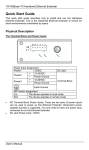
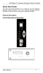
Industrial Ethernet Extender Signamax Connectivity Systems Industrial Ethernet Extender Model - 065-1167 065-1167I 065-1167DIN 065-1167DINI User’s Guide 1 Industrial Ethernet Extender Quick Start Guide This quick start guide describes how to install and use the Ethernet Extender. The Ethernet Extender introduced here provides one channel for Ethernet over existing voice grade copper wire. Product Overview Product Features One 10/100BaseT/TX Ethernet port with RJ-45 connector Auto negotiation of speed and duplex mode on TX port Auto MDIX on TX port Complies with IEEE 802.3 10BaseT and IEEE 802.3u 100BaseTX standards One Ethernet Extender port with RJ-11 connector Ethernet Extender port auto senses the speed of 1/3/5/10/15/20/25/30/40/50Mbps One DIP switch for configuring Ethernet Extender local or remote mode Status LEDs External AC to DC power adapter Used as a stand-alone device or with a chassis Hot-swappable when used with a chassis 2 Industrial Ethernet Extender Packing List When you unpack this product package, you will find the items listed below. Please inspect the contents, and report any apparent damage or missing items immediately to our authorized reseller. The Ethernet Extender User’s Manual AC to DC Power Adaptor 3 Industrial Ethernet Extender Ethernet Extender Mode Settings Ethernet Extender mode settings are made very simple by means of a switch at the rear panel of the Ethernet Extender. The switch has two positions for Ethernet Extender mode settings. Refer to the table below for more details. One device must be set to Loc and the other to Rmt when two devices are connected. Loc Rmt The device operates in local mode The device operates in remote mode Front Panel & LEDs The LED indicators give you instant feedback on status of the Ethernet Extender: LEDs Pwr State Steady Off Indication Power on Pwr stands for POWER Power off Ethernet Steady Lnk/Act Flashing Off Fdx Steady A valid Ethernet connection established Lnk stands for LINK Transmitting or receiving Ethernet data Act stands for ACTIVITY Neither valid Ethernet connection established nor transmitting/receiving Ethernet data Ethernet Connection in full duplex mode Fdx stands for FULL-DUPLEX Ethernet Connection in half-duplex mode Off Ethernet Extender Green The Ethernet Extender port transmitting/receiving at 1Mbps, up to 1900M 1 Amber The Ethernet Extender port transmitting/receiving at 3Mbps, up to 1800M The Ethernet Extender port transmitting/receiving at 5Mbps, up to Green 2 1600M Amber The Ethernet Extender port transmitting/receiving at 10Mbps, up to 1400M Green The Ethernet Extender port transmitting/receiving at 15Mbps, up to 1200M 3 Amber The Ethernet Extender port transmitting/receiving at 20Mbps, up to 1000M Green The Ethernet Extender port transmitting/receiving at 25Mbps, up to 800M 4 Amber The Ethernet Extender port transmitting/receiving at 30Mbps, up to 700M 4+2 Amber The Ethernet Extender port transmitting/receiving at 40Mbps, up to 600M 4+3 Amber The Ethernet Extender port transmitting/receiving at 50Mbps, up to 300M Rmt Steady The device operates in remote mode Loc Steady The device operates in local mode Err Steady Error occurred Lnk Steady A valid connection established Connecting to Power This Ethernet Extender is a plug-and-play device. Connect the supplied AC to DC power adaptor to the receptacle on the rear panel of the Ethernet Extender, and then attach the plug into a standard AC outlet with a voltage range from 100 to 240V AC. 4 Industrial Ethernet Extender Preface This manual describes how to install and use the Ethernet Extender. The Ethernet Extender introduced here provides one channel for Ethernet over existing voice grade copper wire. The Ethernet Extender fully complies with IEEE 802.3 10BaseT and IEEE 802.3u 100BaseTX standards. In this manual, you will find: Product overview Features on the Ethernet Extender Illustrative LED functions Installation instructions Specifications 5 Industrial Ethernet Extender Table of Contents Quick Start Guide .....................................................2 Product Overview............................................................2 Product Features .............................................................2 Packing List .....................................................................3 Ethernet Extender Mode Settings ...................................4 Front Panel & LEDs........................................................4 Connecting to Power .......................................................4 Preface .......................................................................5 Table of Contents ......................................................6 Introduction ..............................................................7 Product Overview............................................................7 Product Features .............................................................7 Packing List .....................................................................7 One-Channel Ethernet Extender ..............................8 Ports.................................................................................8 Ethernet Extender Mode Settings ...................................8 Front Panel & LEDs........................................................8 Installation............................................................... 10 Selecting a Site for the Equipment ................................ 10 Connecting to Power ..................................................... 10 Installing in a Chassis.................................................... 11 Specifications........................................................... 13 Contact Information ............................................... 14 6 Industrial Ethernet Extender Introduction The Ethernet Extender provides one channel for Ethernet over existing voice grade copper wire. It can be used as a stand-alone device or with a standard 19” chassis. Product Overview Product Features One 10/100BaseT/TX(TX) Ethernet port with RJ-45 connector Auto negotiation of speed and duplex mode on TX port Auto MDIX on TX port Complies with IEEE 802.3 10BaseT and IEEE 802.3u 100BaseTX standards One Ethernet Extender port with RJ-11 connector Ethernet Extender port auto senses the speed of 1/3/5/10/15/20/25/30/40/50Mbps One switch for configuring Ethernet Extender local or remote mode Status LEDs External AC to DC power adapter Used as a stand-alone device or with a chassis Hot-swappable when used with a chassis Packing List When you unpack this product package, you will find the items listed below. Please inspect the contents, and report any apparent damage or missing items immediately to our authorized reseller. The Ethernet Extender User’s Manual AC to DC Power Adaptor 7 Industrial Ethernet Extender One-Channel Ethernet Extender Ports The Ethernet Extender provides one TX port and one Ethernet Extender port. For the TX port, it uses RJ-45 connector and auto senses the speed of 10/100 Mbps. For the Ethernet Extender port, it uses RJ-11 connector and auto senses the speed of 1/3/5/10/15/20/25/30/40/50Mbps. Ethernet Extender Mode Settings Ethernet Extender mode settings are made very simple by means of a 2 position switch at the rear panel of the Ethernet Extender. Mode switch There is one position on the Mode switch for Ethernet Extender mode settings. Refer to the table below for more details. One end must be set to Loc and the other to Rmt when two devices are connected. Loc Rmt The device operates in local mode The device operates in remote mode Front Panel & LEDs LED Indicators The LED indicators give you instant feedback on status of the Ethernet Extender: 8 Industrial Ethernet Extender LEDs Pwr State Steady Off Indication Power on Pwr stands for POWER Power off Ethernet A valid Ethernet connection established Lnk stands for LINK Transmitting or receiving Ethernet data Lnk/Act Flashing Act stands for ACTIVITY Neither valid Ethernet connection established nor transmitting/receiving Ethernet Off data Ethernet Connection in full duplex mode Steady Fdx Fdx stands for FULL-DUPLEX Off Ethernet Connection in half-duplex mode Ethernet Extender Green The Ethernet Extender port transmitting/receiving at 1Mbps, up to 1900M 1 Amber The Ethernet Extender port transmitting/receiving at 3Mbps, up to 1800M Green The Ethernet Extender port transmitting/receiving at 5Mbps, up to 1600M 2 Amber The Ethernet Extender port transmitting/receiving at 10Mbps, up to 1400M Green The Ethernet Extender port transmitting/receiving at 15Mbps, up to 1200M 3 Amber The Ethernet Extender port transmitting/receiving at 20Mbps, up to 1000M Green The Ethernet Extender port transmitting/receiving at 25Mbps, up to 800M 4 Amber The Ethernet Extender port transmitting/receiving at 30Mbps, up to 700M 4+2 Amber The Ethernet Extender port transmitting/receiving at 40Mbps, up to 600M 4+3 Amber The Ethernet Extender port transmitting/receiving at 50Mbps, up to 300M Rmt Steady The device operates in remote mode Loc Steady The device operates in local mode Err Steady Error occurred Lnk Steady A valid connection established Steady 9 Industrial Ethernet Extender Installation This chapter gives step-by-step installation instructions for the Ethernet Extender. Selecting a Site for the Equipment As with any electric device, you should place the equipment where it will not be subjected to extreme temperatures, humidity, or electromagnetic interference. Specifically, the site you select should meet the following requirements: The ambient temperature should be between -20 to 60 degrees Celsius. The relative humidity should be less than 90 percent, non-condensing. Surrounding electrical devices should not exceed the electromagnetic Make sure that the equipment receives adequate ventilation. Do not The power outlet should be within 1.8 meters of the product. field (RFC) standards. block the ventilation holes on each side of the equipment. Connecting to Power This Ethernet Extender is a plug-and-play device. Connect the supplied AC to DC power adaptor to the receptacle on the rear panel of the Ethernet Extender, and then attach the plug into a standard AC outlet with a voltage range from 100 to 240VAC. 10 Industrial Ethernet Extender Installing in a Chassis The Ethernet Extender can be fit into any of the expansion slots on a special designed chassis. First, install the Ethernet Extender onto a carrier supplied with the chassis: Step 1- Unscrew the carrier from the desired expansion slot on the chassis. Step 2- Fit the Ethernet Extender onto the carrier. 11 Industrial Ethernet Extender When the Ethernet Extender is completely seated onto the carrier, insert the carrier to the guide rails of the expansion slot. Carefully slide in the carrier until it is fully and firmly fit the chassis. Fasten the screws onto the carrier. <NOTE> Never insert any Ethernet Extender into the chassis directly without using the supplied carriers. The carriers allow secure and consistent placement of the Ethernet Extenders into the chassis backplane without causing any damage. 12 Industrial Ethernet Extender Specifications Applicable Standards Fixed Ports Speed 10BaseT 100BaseTX Ethernet Extender Cable 10BaseT 100BaseTX Ethernet Extender Switching Method IEEE 802.3 10BaseT IEEE 802.3u 100BaseTX Ethernet over VDSL 1 x 10/100Mbps Ethernet port with RJ-45 connector 1 x Ethernet Extender port with RJ-11 connector 10/20Mbps for half/full-duplex 100/200Mbps for half/full-duplex 1, 3, 5, 10, 15, 20, 25, 30, 40, 50Mbps 2-pair UTP/STP Cat. 3, 4, 5 2-pair UTP/STP Cat. 5 Telephone wires Store-and-Forward Forwarding rate 14,880/148,810pps for 10/100Mbps LED Indicators Per Unit- (7 LEDs): Pwr; Rmt, Loc, 1, 2, 3, 4 Dimensions Weight Power Power Consumption Operating Temperature Storage Temperature Humidity Safety Emissions Per PortRJ-45 (2 LEDs): Lnk/Act; Fdx RJ-11 (2 LEDs): Err, Lnk 80.3mm (W) × 109.2mm (D) × 23.8mm (H) (3.16” (W) x 4.30” (D) x 0.94” (H)) 150g (0.33lb.) External power adaptor 12VDC, 0.2A 2.4W Max. -20°C ~ 60°C -20°C ~ 70°C 5 ~ 95%, non-condensing UL60950-1 FCC part 15 Class A, CE Mark Class A 13