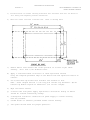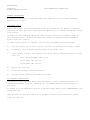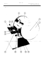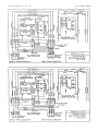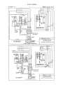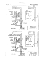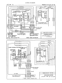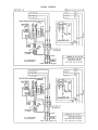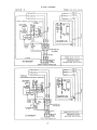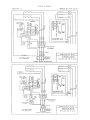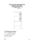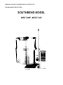
1
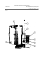
MANUAL FOR SELF-GENERATING COUNTER-TOP
STEAM JACKETED KETTLES
SOUTHBEND MODEL
KECT-05F, KECT-10F
SELF-GENERATING COUNTER TOP
STEAM JACKETED KETTLES
INDEX
CROWN suggests that this entire manual be read thoroughly and that all instructions be followed carefully.
SECTION
PAGE
Inside Front Cover
DESCRIPTION
Warranty, Damages, etc.
1
2
Introduction - Description
- Capacities
- Functioning Mode
2
4
Operating Controls and Indicators
3
6
Installation Instructions
4
7
Operating and Cleaning Instructions
5
8
Maintenance
6
9
Service Information
7
10
Parts Lists
8
15
Wiring Diagrams
INTRODUCTION
Section 1:
SELF-GENERATING COUNTER TOP
STEAM JACKETED KETTLES
DESCRIPTION
All CROWN electrically powered kettles described and referred to in this manual are
pressure vessels of a double-wall stainless steel construction forming a sealed
jacket (chamber) enveloping the tower two thirds of the kettle bowl surface.
The kettle bowl is the container for the food product which ideally should be of a
liquid or semi-liquid consistency to achieve complete contact with the bowl surface
and thus fully absorb the heat transmitted through that surface from the pressurized
steam generated in the kettle jacket.
The jacket is intended to function as a self contained sealed chamber with a
permanent solution of water and anti-freeze sufficient not only to immerse and
thereby protect replaceable electric heating elements but also provide the steam
source during the steam generating process.
The heating elements are thermostatically dial controlled to provide precise
temperatures throughout the range from slow simmer to rolling boil.
Each kettle is rigidly suspended on a horizontal shaft which is supported by, and
allowed to rotate within the console housing thereby making it possible to tilt the
kettle.
Removal of the food product occurs when the kettle is tilted and contents are
directed by the pouring lip into an appropriate container.
All models are intended for permanent mounting to a counter top or suitable
stand.
CAPACITIES
All EC models are suffixed with either -5, -6, -10 or -20 to indicate the capacity of
that kettle in U.S. Gallons. Thus an EC-5 indicates an electric self steam
generating jacketed counter top kettle with a capacity of 5 gallons (U.S.).
FUNCTIONING MODE
All CROWN electrically powered self steam generating kettles consist of a jacket
containing a permanent solution of water and anti-freeze sufficient to completely
immerse and protect replaceable electric heating elements. A low water sensing
probe, as a protective device, is installed in each kettle jacket which will
automatically interrupt heating element operation and turn on the WATER REQUIRED
warning light whenever water level is insufficient to immerse not only the probe but
also the elements.
INTRODUCTION
SECTION 1:
SELF-GENERATING COUNTER TOP
STEAM JACKETED KETTLES
FUNCTIONING MODE - continued
On all tilting kettles the low water sensing probe is installed at the rear of the kettle jacket and during the
pouring operation, as the kettle is tilted forward, the water within the jacket also flows forward exposing
the heating elements and the low water sensing probe and consequently interrupts power supply to the
heating elements. Additionally, each tilting kettle has installed an interlock switch which will also interrupt
the power supply to the heating elements whenever the kettle is not in its normal upright position, i.e.
tilted.
When the Power Switch is turned ON and the Thermostat Knob dialed, simultaneously Temperature pilot
light will glow and contactors will close to allow power to elements and steam generation will commence
and continue until the water contained in the jacket reaches the thermostatic temperature, manually preselected, at which point the thermostat control will de-energize and open the contactors cutting off power
to elements and Temperature pilot light will go off. When the temperature of the water in the jacket drops
slightly, the cycle will repeat itself thus making it possible to maintain any selected precise cooking mode
temperature.
The temperature required for the cooking process to function adequately must be greater than the boiling
point of the liquid food product, viz. water. Further, the higher the temperature, the greater the steam
pressure attained in the jacket and consequently the quicker the cooking process. For example, steam
pressurized at 30 p.s.i. attains a temperature of 274°F.
It should be noted that since air is an unsuitable media through which heat may be transferred, it has
been removed from the kettle jacket during testing at Crown. The Pressure Gauge should indicate
vacuum pressure in the jacket of approximately 20 - 25 p.s.i. when the kettle is not in operation. The
kettle jacket is intended to function at all times as a completely sealed self contained chamber and it is
especially advisable not to trip the safety relief valve during inoperative periods since this will break the
vacuum seal and allow air to enter the kettle jacket.
OPERATING CONTROLS AND INDICATORS
SECTION 2:
SELF-GENERATING COUNTER TOP
STEAM JACKETED KETTLES
FIG. 1
OPERATING CONTROLS AND- INDICATORS
Section 2:
SELF-GENERATING COUNTER TOP
STEAM JACKETED KETTLES
Fig. 1:
Shows physical location of Controls, Indicators and Operating features. Listed and itemized is a
short functional description of each.
Item A:
Kettle Power Switch controls power to kettle.
Item B:
Thermostat Knob allows operator to select kettle temperature in increments from "1" to '10'.
Covers range from low simmer to rolling boil.
Item C:
Temperature pilot light functions in conjunction with Thermostat Knob and when lit indicates
heating elements are on. Cycles on and off according to thermostat control setting.
Item D:
Water Required pilot light when lit indicates insufficient water in kettle jacket and protective
sensing probe has interrupted power supply to controls and heating elements. Note that tilting of
kettle will activate a similar condition but does not necessarily indicate a low water situation.
Item E:
Pressure Gauge indicates vacuum in inches of mercury and pressure in pounds per square inch
inside kettle jacket.
Item F:
Tilting Handle used to tilt kettle forward for pouring.
Item G:
Safety Relief Valve located at rear of kettle jacket opens automatically should malfunction cause
excessive steam pressure to occur in kettle jacket.
Item H:
Air Vent Nut located at rear of kettle jacket allows air to be removed from jacket should vacuum
seal be broken.
INSTALLATION INSTRUCTIONS
SECTION 3:
SELF-GENERATING COUNTER TOP
STEAM JACKETED KETTLES
a)
Position kettle on counter allowing sufficient rear clearance from wall for kettle to
tilt freely and completely without obstruction.
b)
Mark four corner locations of kettle base.
c)
Remove kettle from counter and locate position of 4 holes as per above
drawing. Drill four 7/16" diameter holes.
d)
Apply a continuous bead of Silastic or other equivalent sealant
along the complete perimeter edge of the kettle base and reposition kettle on
counter.
e)
Use 5/16-18 Hex Cap Screws with suitable flat washers to bolt
down.. Screw lengths must be 1-1/4" long plus counter top thickness. (EC-20
Counter Top Models require an additional 1/2" of bolt length).
f)
Wipe off excess sealant
g)
A Control Box with power supply equivalent to Electrical Rating of kettle
should be located conveniently nearby.
h)
i)
A waterproof electrical connection for power supply to console housing
must be provided.
Ground kettle to terminal provided inside console housing.
j)
Turn power ON and check for proper operation.
Refer to drawing below
OPERATING AND CLEANING INSTRUCTIONS
SECTION 4:
SELF-GENERATING COUNTER TOP
STEAM JACKETED KETTLES
OPERATING PROCEDURE
a)
Check that external Control Box Switch is ON.
b)
Check kettle Pressure Gauge that reading indicates 20 - 25 vacuum for a
cold kettle. If vacuum is insufficient. Air Venting Instructions must be
followed.
c)
Place Kettle Power Switch in ON position.
d)
Preheat kettle by turning Thermostat Knob to '8'
Temperature pilot light goes off.
NOTE:
and wait until
Food products with milk or egg base should be placed into cold
kettle and then the cooking operation begun. Avoid sudden
contact of these food products to hot kettle bowl surface since
caking and adhering will occur.
e)
Place food product into kettle bowl.
f)
Adjust Thermostat Knob to temperature cooking mode. Setting of
4 - 6 will provide simmer and 7-10 low to rolling boil.
g)
Turn both kettle Power Switch and Thermostat Knob OFF when cooking has
been completed.
h)
Remove food product by ladling out of kettle bowl or by tilting
and pouring into a suitable container.
i)
Clean immediately to prevent residue from drying and adhering to
kettle bowl surface.
CLEANING PROCEDURE
a)
Turn power supply OFF to kettle.
b)
Using a nylon brush, scrub kettle bowl with a warm water mild
detergent wash solution. Never use steel wool or abrasive scouring pads
as they will scratch and ruin the general appearance of the kettle and
make it more difficult subsequently to maintain in a clean sanitary
condition.
c)
Tilt kettle and pour out wash solution.
d)
Rinse kettle bowl with clean water and dry.
e)
Food adhering excessively to bowl surface may be loosened by
allowing water to soak in bowl at a low temperature setting.
Wipe down exterior of kettle and console housing with clean damp cloth.
f)
NEVER SPRAY WATER INTO ELECTRIC CONTROLS
MAINTENANCE
SECTION 5:
STEAM JACKETED KETTLES
SELF-GENERATING COUNTER TOP
GENERAL MAINTENANCE
No general maintenance is required other than adhering to the Cleaning Procedure
instructions on page 7.
LOW WATER LEVEL
Proper water level must be maintained within the jacket for the kettle to operate.
Depletion of water may occur from excessive opening of, or leakage through the safety
relief valve.
If water is below required operating level, either initially at startup or during
use, the kettle will automatically shut off, refuse to operate and the LOW WATER
signal light will come on.
In order for the kettle to operate, the following procedure must be followed a)
Trip the safety relief valve lever to relieve all pressure from kettle jacket.
b)
At exterior rear of kettle jacket remove nut from Air Vent.
c)
Insert funnel into Air Vent opening and slowly add the indicated amount of clean
water for
EC-5 and EC-6 Models add 52 ozs.
EC-10 Model add 108 ozs.
EC-20 Model add 144 ozs.
d)
Replace Air Vent nut.
e)
Follow Air Venting Instructions below.
f)
Continue normal Operating Procedure of kettle.
AIR VENTING INSTRUCTIONS
Periodically check Pressure Gauge when the kettle is cold. Reading should be in
VACUUM zone between 20 to 25, otherwise air is present and efficient heating will
not occur.
To remove air, set Thermostat Knob at 8 and heat empty kettle until TEMPERATURE pilot
tight goes off.
Open Air Vent nut one full turn for 10 seconds to exhaust air from kettle jacket.
Close Air Vent nut.
SERVICE INFORMATION
SECTION 6
SELF-GENERATING COUNTER TOP
STEAM JACKETED KETTLES
EXTREMELY SLOW COOKING TIME
If the cooking time is abnormally slow then the difficulty may be due to air being
present in the kettle jacket. To remove air, follow AIR VENTING INSTRUCTIONS on page
8.
If this problem persists and kettle will not reach and maintain Pressure Gauge zone
of 20 - 25 Vacuum when cold, then assume that a slow leak may be responsible in the
jacket. Check all fitting connections to jacket and also element gasket. Tighten or
replace if necessary.
Slow cooking time may also be due to a burnt out heating element. Test
elements and if defective replace complete element assembly.
KETTLE WILL NOT OPERATE WHEN TURNED ON
Check that power supply is available to kettle.
Kettle will not operate if water level is inadequate in jacket.
LEVEL instructions on page 8.
Follow LOW WATER
If water level is sufficient and kettle refuses to operate, then check that
Interlock Switch in Console is fully engaged when kettle is in its normally
upright position. Adjust Retaining Collar if necessary to assure complete
contact with switch and if kettle still refuses to operate, then check for
defective switch and/or loose wiring connections.
Initially, when Termostat Knob is dialed and TEMPERATURE indicator light does not
come on, then it may be assumed that malfunction is due to either a defective
Thermostat or loose wiring connection(s). If TEMPERATURE indicator light comes on
when Thermostat Knob is dialed fully (i.e. setting of '10'). then eventually the
kettle should reach its maximum temperature (290°F) in the jacket and a corresponding
pressure reading of approximately 40 p.s.i. should be evident on the Pressure Gauge,
(on kettles, rated,at 50-p.s.i)
Finally, when the kettle is turned ON and Thermostat Knob dialed, check that the
Contactors.are being energized and power is being made available to the heating
elements. Replace defective Contactors.
PARTS LIST
SECTION 7:
FIG.
2
SELF-GENERATING COUNTER TOP
STEAM JACKETED KETTLES
PARTS LIST
SELF-GENERATING COUNTER TOP
STEAM JACKETED KETTLES
From Fig. 2
ITEM NO.
PART NO.
DESCRIPTION
QUANTITY
EC-5&-6
EC-10
EC-20
1
8-3090
8-3091
8-3120
Kettle Enclosure Cover
1
2
1-65S4
1-65S4
1-65S4
Enclosure Cover Bolt
1
3
3-AV01
3-AV01
3-AV01
Air Vent Assembly
1
4
3-SRV8
3-SRV8
3-SRV8
Safety Relief Valve (50 psi)
1
5
8-3092
8-3092
8-3142
Tilt Handle
1
6
2-KB01
2-KB01
2-KB01
Knob for Handle
1
7
4-S101
4-S101
4-S101
Power Switch
1
8
8-3087
8-3087
8-3087
Retaining Collar
1
9
4-M605
4-M605
4-M605
Interlock Switch
1
1-11 C7
1-11C7
1-11C7
Fastening Screws for Item 9
2
10
8-3103
8-3103
8-3103
Element Access Cover
1
n
1-33S2
1-33S2
1-33S2
Access Cover Screws
2
12
8-3028
8-3029
8-3119
Trunnion Box Cover
1
13
1-33S2
1-33S2
1-33S2
Trunnion Box Screws
2
14
8-3143
8-3144
8-3145
Housing & Base Assembly
1
PARTS LIST
SECTION 7:
SELF-GENERATING COUNTER TOP
STEAM JACKETED KETTLES
FIG.
3
PARTS LIST
SELF-GENERATING COUNTER TOP STEAM
JACKETED KETTLES
From Fig. 3
ITEM NO.
PART NO.
DESCRIPTION
QUANTITY
EC-5&-6
EC-10
EC-20
1
4-70EU
4-70EU
4-70EU
Ground Terminal
1
2
4-LLC1
4-LLC1
4-LLC1
Liquid Level Control
1
3
4-NG41
4-NG41
4-NG41.
Contactor 208,240(2)380,416,480 (1)
4
4-33T8
4-33T8
4-33T8
Terminal Block
1
5
1-65S6
1-65S6
1-65S6
Flange Bolt
4
6
1-60S0
1-60S0
1-60S0
Lock Washer
4
7
8-3146
8-3147
8-3147
Gasket
1
Element & Flange Assembly
1
8
see page 14
9
4-LLP1
4-LLP1
4-LLP1
Probe
1
10
3-68CC
3-68CC
3-68CC
Connector
1
11
8-3148
8-3149
8-3150
Copper Tube
1
12
3-66CB
3-66CB
3-66CB
Connector
1
13
1-49CO
1-49CO
1-49CO
Nut
2
14
3-PG00
3-PG00
3-P600
Pressure Gauge
1
15
8-3097
8-3097
8-3097
Mounting Plate
1
16
3-T8EC
3-T8EC
3-T8EC
Thermostat Bulb Connector
1
17
4-TH05
4-TH05
4-TH05
Thermostat
1
18
4-TK05
4-TK05
4-TK05
Thermostat Knob (not shown)
1
19
4-TB05
4-TB05
4-TB05
Thermostat Bezel (not shown)
1
20
1-13C3
1-13C3
1-13C3
Thermostat Screws (not shown)
1
21
8-3015
8-3015
8-3015
Console Lid
1
22
1-33S2
1-33S2
1-33S2
Console Screw (not shown)
1
23
4-PL08
4-PL08
4-PL08
Low Water Pilot Light (n.s.)
1
24
4-PL08
4-PL08
4-PL08
Temperature Pilot Light (n.s.)
1
ELEMENT LIST
SECTION 7:
SELF-GENERATING COUNTER TOP
STEAM JACKETED KETTLES
Ref. Page 11 - Item 22
MODELS EC-5 & EC-6 (7.5 KH Elements)
VOLTAGE
ELEMENT NO.
TRANSFORMER NO.
208
230
240
220/380
240/416
380
416
480
7-5015
7-5045
7-5017
7-5016
7-5017
7-5016
7-5017
7-5018
not required
not required
not required
not required
not required
4-T251 *
4-T253 *
4-T255 *
MODELS EC-10 & EC-20
(12 KW Elements)
VOLTAGE
ELEMENT NO.
TRANSFORMER NO.
208
230
240
220/380
240/416
380
416
480
7-5019
7-5046
7-5021
7-5020
7-5021
7-5020
7-5021
7-5022
not required
not required
not required
not required
not required
4-T251 *
4-T253 *
4-T255 *
* Require Fuse Part No. 4-FU03 and Fuseholder Part No. 4-FH03
WIRING DIAGRAMS SECTION
8:
MODELS EC-5 & EC-6
WIRING DIAGRAMS SECTION
8:
MODELS EC-5 & EC-6