1
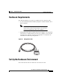
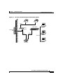
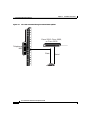
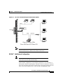
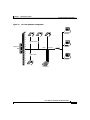
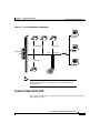
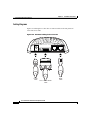
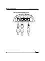
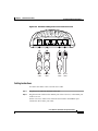
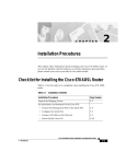
C H A P T E R
2
Installation Procedures
This chapter provides information about installing the Cisco 600 series CPE
devices.
Installation Checklist
Table 2-1 lists the tasks to be completed when installing the Cisco 600 series
CPE.
Table 2-1
Installation Checklist
Installation Procedures
Page Number
Unpack the Shipping Carton
2-2
Set Up the Hardware Environment:
•
Connect the Management Port to the PC’s COM Port
2-4
•
Configure the PC’s COM Port
2-5
•
Possible Configurations
2-5
•
Connect Cables to the CPE
2-13
•
Power On the CPE
2-18
Cisco 600 Series Installation and Operation Guide
78-11190-01
2-1
Chapter 2
Installation Procedures
Unpack the Shipping Carton
Unpack the Shipping Carton
Check the shipping carton carefully to ensure that the contents include the items
you ordered. You can identify the Cisco 600 series CPE by the product name on
the top of the unit at the end with the LEDs.
The contents of your carton might vary depending on your service provider.
Tables 2-2 and 2-3 show a list of the standard contents of a Cisco 600 series CPE
shipment.
Table 2-2
Standard Shipment Contents
Contents
Description
Cisco 600 series CPE
Cisco DSL CPE for home/office use.
Quick Start for the Cisco 6xx
Quick start information for the
specific Cisco 600 series CPE model.
Table 2-3
Standard Cables Shipped
Cable
627
633
673
675
675e 676
677
678
Power supply—Worldwide AC
power adapter
ADSL/SDSL cable—RJ-11
telephone cable (14 ft)
ATM25 cable—Category 5
cable (6 ft)
Ethernet cable—Yellow
Ethernet category 5 “no-hub”
twisted pair crossover cable (6
ft)
SERIAL cable
(Blue)—12-in-1 Smart Serial
connector
If any items you ordered were not delivered, contact Cisco.
Cisco 600 Series Installation and Operation Guide
2-2
78-11190-01
Chapter 2
Installation Procedures
Hardware Requirements
Hardware Requirements
The following hardware is necessary to configure the Cisco 600 series CPE:
•
PC with a standard terminal emulation program or a dumb terminal, with a
DB-9 COM port.
Note
•
If only a DB-25 serial port is available on the computer,
a DB-9-male-to-DB-25-female adapter is also needed to
connect the management cable to the computer.
Management cable (RJ-45-to-DB-9) like the one in Figure 2-1 to connect the
CPE to the PC or dumb terminal you will use to configure it. You can order
one from Cisco or provide your own. See Appendix A, “Connectors” for
information on connector pin assignments.
Management Cable
18429
Figure 2-1
Set Up the Hardware Environment
This section describes how to connect the Cisco 600 series CPE.
Cisco 600 Series Installation and Operation Guide
78-11190-01
2-3
Chapter 2
Installation Procedures
Set Up the Hardware Environment
Note
Electrical equipment generates heat. Ambient air temperature might
not be adequate to cool equipment to acceptable operating
temperatures without adequate circulation. Ensure that the room in
which you operate the CPE has adequate air circulation.
Be careful not to block the air vents on the CPE.
Connect the Management Port to the PC’s COM Port
Step 1
Connect the RJ-45 connector on the management cable to the MGMT port on the
CPE.
Step 2
Connect the other end of the management cable to the computer’s COM port. If
your computer is equipped only with a DB-25 serial port, you need a
DB-9-male-to-DB-25-female adapter.
Figure 2-2
Cisco 600 series CPE Management Port Cabling
6xx
MGMT
WALL
35377
110
Cisco
PWR
Cisco 600 Series Installation and Operation Guide
2-4
78-11190-01
Chapter 2
Installation Procedures
Set Up the Hardware Environment
Configure the PC’s COM Port
For the best access to the CBOS, use your terminal emulation program (such as
HyperTerminal in Windows) to set your COM protocol to the following settings:
•
Baud rate: 38400 bps recommended (standard 9600 bps possible)
•
Data bits: 8
•
Parity: None
•
Stop bits: 1
•
Flow control: None
Possible Configurations
This section shows you different ways of connecting your Cisco 600 series CPE
to your telephone and computer equipment, depending on whether or not your
telephone equipment is connected to a POTS splitter.
Table 2-4 shows the configurations that will work with each Cisco 600 series CPE
model.
Table 2-4
Network Configurations
Configuration
627
633
673
675
675e 676
677
678
POTS Splitter
EZ-DSL (Splitterless)
Back-to-back
(bridging mode only)
Back-to-Back Cabling (Cisco 633 and Cisco 673 only)
You can connect two Cisco 633s or Cisco 673s in a “back-to-back” configuration.
This allows one CPE to terminate the traffic of a second CPE without central
office (CO) equipment. This configuration can be used as a low-cost solution for
communicating between two locations at a distance greater than Ethernet’s
Cisco 600 Series Installation and Operation Guide
78-11190-01
2-5
Chapter 2
Installation Procedures
Set Up the Hardware Environment
100-meter range. The two locations must be directly connected, for example,
through some internally owned telephone system wiring in a campus-type
environment.
Step 1
At the first location, connect one end of the SDSL cable into the WALL port on
one of the Cisco 633 or Cisco 673 units. Connect the other end of the SDSL cable
into the wall jack.
Step 2
At the second location, connect one end of the second SDSL cable into the WALL
port of the second Cisco 633 or Cisco 673 unit. Connect the other end of the
second SDSL cable into the wall jack.
Step 3
Configure the CPE that you want to terminate traffic to operate in CO mode and
the other to operate in CPE mode. See the “Attention Back-to-Back Connection
Users” section on page 4-5 for more information.
Note
Back-to-back configuration works in bridging mode only.
POTS Splitter Configuration (Required for the Cisco 627)
A POTS splitter separates data signals from voice signals on your telephone line.
The POTS splitter works by running a separate data line from the voice line, so
that the CPE has a dedicated cable for data transmission. Figure 2-3, Figure 2-4,
and Figure 2-5 show telephone equipment connected to a POTS splitter.
Cisco 600 Series Installation and Operation Guide
2-6
78-11190-01
Chapter 2
Installation Procedures
Set Up the Hardware Environment
Figure 2-3
Cisco 627 Connected through an Internal POTS Splitter
Voice
Telephone
NID
Cisco 3600
POTS
Splitter
Data
Cisco 4101
ATM25
35385
Ethernet
Cisco 627
Cisco 600 Series Installation and Operation Guide
78-11190-01
2-7
Chapter 2
Installation Procedures
Set Up the Hardware Environment
Figure 2-4
Cisco 633 Connected through an Internal POTS Splitter
Cisco 2500, Cisco 2600,
or Cisco 3600
Cisco 4101
Telephone
NID
Data
Serial
Cisco 600 Series Installation and Operation Guide
2-8
78-11190-01
Chapter 2
Installation Procedures
Set Up the Hardware Environment
Figure 2-5
Cisco 67x Connected through an Internal POTS Splitter
Voice
POTS
Splitter
Telephone
NID
Data
Ethernet
35386
Hub
Cisco 675/Cisco 675e/
Cisco 676/Cisco 677/Cisco 678
Note
The POTS splitter can also be installed adjacent to the telephone
network interface device (NID) on the outside of the house.
EZ-DSL™ (Splitterless) Configuration
Note
This configuration applies to the Cisco 627, Cisco 675, Cisco 675e,
Cisco 676, Cisco 677, and Cisco 678 only.
In the EZ-DSL configuration, your telephone equipment is not connected to a
POTS splitter. Without a POTS splitter and under certain circumstances, transient
noise from a telephone can interfere with the router’s operation, and the router can
cause noise on the telephone line. To prevent this from happening, small
Cisco 600 Series Installation and Operation Guide
78-11190-01
2-9
Chapter 2
Installation Procedures
Set Up the Hardware Environment
microfilters must be connected to the telephone lines. If you implement an
EZ-DSL configuration, your installation landscape should look similar to
Figure 2-6, Figure 2-7, Figure 2-8, or Figure 2-9.
Figure 2-6
Cisco 627 Splitterless Configuration
Ethernet
Microfilter
Cisco 3600
Telephone
NID
Data
ATM25
Cisco 4101
35454
Microfilter
Cisco 627
Cisco 600 Series Installation and Operation Guide
2-10
78-11190-01
Chapter 2
Installation Procedures
Set Up the Hardware Environment
Figure 2-7
Cisco 675 Splitterless Configuration
Microfilters
Telephone
NID
Data
Ethernet
35378
Hub
Microfilter
Cisco 675
Cisco 600 Series Installation and Operation Guide
78-11190-01
2-11
Chapter 2
Installation Procedures
Set Up the Hardware Environment
Figure 2-8
Cisco 675e, Cisco 676, Cisco 677 Splitterless Configuration
Microfilters
Telephone
NID
Data
Ethernet
35379
Hub
Microfilter
Cisco 675e/Cisco 676/
Cisco 677
Cisco 600 Series Installation and Operation Guide
2-12
78-11190-01
Chapter 2
Installation Procedures
Set Up the Hardware Environment
Figure 2-9
Cisco 678 Splitterless Configuration
Microfilters
Telephone
NID
Microfilter
Data
Ethernet
31519
Hub
Microfilter
Cisco 678
Note
The microfilters do not work if connected improperly. For
connection instructions, see Appendix C, “EZ-DSL Microfilter
Specifications.”
Connect Cables to the CPE
This section describes how to connect cables to the CPE and to your telephone
and computer systems.
Cisco 600 Series Installation and Operation Guide
78-11190-01
2-13
Chapter 2
Installation Procedures
Set Up the Hardware Environment
Cabling Diagrams
Figures 2-10 through 2-13 show how to connect cables to the rear panels of
Cisco 600 series CPEs.
PWR
Power
cable
SERIAL
12-in-1 Smart Serial
cable
MGMT
WALL
24591
Figure 2-10 Rear Panel Cabling for the Cisco 633
SDSL
cable
Cisco 600 Series Installation and Operation Guide
2-14
78-11190-01
Chapter 2
Installation Procedures
Set Up the Hardware Environment
PWR
ATM25
Power
cable
ATM25
cable
MGMT
WALL
18432
Figure 2-11 Rear Panel Cabling for the Cisco 627
ADSL
cable
Cisco 600 Series Installation and Operation Guide
78-11190-01
2-15
Chapter 2
Installation Procedures
Set Up the Hardware Environment
PWR
Power
cable
ENET
Ethernet
cable
MGMT
WALL
28553
Figure 2-12 Rear Panel Cabling for the Cisco 673, Cisco 675e, Cisco 676, and
Cisco 677
DSL
cable
Cisco 600 Series Installation and Operation Guide
2-16
78-11190-01
Chapter 2
Installation Procedures
Set Up the Hardware Environment
PWR
Power
cable
ENET
MGMT
Ethernet
cable
WALL
ADSL
cable
PHONE
24555
Figure 2-13 Rear Panel Cabling for the Cisco 675 and Cisco 678
Phone
cable
Cabling Instructions
To connect the cables to the Cisco 600 series CPE:
Step 1
Plug the power cable into the back of the unit.
Step 2
Plug the network cable into the ATM25 port of the Cisco 627, or the ENET port
of the Cisco 67x.
For the Cisco 633, connect one end of the serial cable to the SERIAL port.
Connect the other end to your router.
Cisco 600 Series Installation and Operation Guide
78-11190-01
2-17
Chapter 2
Installation Procedures
Power On the CPE
For the Cisco 627, connect the other end of the network cable to your premises
router, for example, a Cisco 3600 series router.
For the Cisco 67x, if the customer premises has only a single Ethernet-equipped
computer, attach the Cisco 600 series CPE to the computer’s Ethernet adapter
with the crossover cable provided. Otherwise, connect the Cisco 600 series CPE
Ethernet port to an Ethernet hub via a straight-through cable (not provided).
Step 3
Connect the telephone cable to the WALL port. Connect the other end of the
telephone cable in the appropriate configuration as discussed in the “Possible
Configurations” section on page 2-5.
Step 4
(Optional step for the Cisco 678) Plug the microfilter into the PHONE port. Then
plug the telephone into the microfilter.
Note
Step 5
Never connect a telephone directly to the PHONE port of the
Cisco 678; this affects the CPE’s performance.
(Optional step for the Cisco 675) Plug the telephone into the PHONE port. The
telephone can be connected directly to the PHONE port of the Cisco 675 because
it uses a built-in microfilter.
Power On the CPE
Step 1
Connect power to the Cisco 600 series CPE by plugging the power supply into an
appropriate electrical outlet.
Note
Use only the Cisco-approved power supply that shipped
with the CPE as your power supply.
Note
Cisco recommends that you unplug your CPE when you are
not using it.
Cisco 600 Series Installation and Operation Guide
2-18
78-11190-01
Chapter 2
Installation Procedures
Next Step
Step 2
When you have powered up the Cisco 600 series CPE, check that the Power LED
is ON.
Step 3
If the Power LED is not lit, immediately remove the barrel power connector from
the Cisco 600 series CPE. Refer to Chapter 6, “Troubleshooting,” for information.
Note
To power down the Cisco 600 series CPE, unplug the power supply
cable from the Cisco 600 series CPE rear panel PWR connector.
Next Step
Now that you have installed and powered on your Cisco 600 series CPE, you must
configure it.
To configure the Cisco 627, see Chapter 3, “Configuration Procedures for the
Cisco 627.”
To configure the Cisco 633, see Chapter 4, “Configuration Procedures for the
Cisco 633.”
To configure the Cisco 673, Cisco 675, Cisco 67e, Cisco 676, Cisco 677 or
Cisco 678, see Chapter 5, “Configuration Procedures for the Cisco 67x CPE
Devices.”
Warnings and Cautions
Warning
To prevent dangerous overloading of the power circuit, read the
label on the bottom of the Cisco 600 series CPE that indicates
maximum power load ratings. Failure to follow these rating
guidelines could result in a dangerous situation.
Cisco 600 Series Installation and Operation Guide
78-11190-01
2-19
Chapter 2
Installation Procedures
Warnings and Cautions
Warning
Do not use this product near water; for example, near a bath tub,
wash bowl, kitchen sink or laundry tub, in a wet basement, or near
a swimming pool.
Warning
Never install telephone wiring during an electrical storm.
Warning
Never install telephone jacks in wet locations unless the jack is
specifically designed for wet locations.
Warning
Never touch uninsulated telephone wires or terminals unless the
telephone line has been disconnected at the network interface.
Caution
Use caution when installing or modifying telephone lines.
Warning
Avoid using a telephone (other than a cordless type) during an
electrical storm. There may be a remote risk of electric shock from
lightning.
Warning
Do not use a telephone to report a gas leak in the vicinity of the
leak.
Cisco 600 Series Installation and Operation Guide
2-20
78-11190-01