1
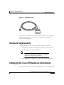
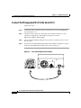
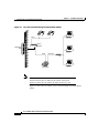
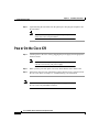
C H A P T E R
2
Installation Procedures
This chapter offers information about installing your Cisco 678 ADSL router. If
you are not familiar with the hardware or software parameters presented here,
please consult your service provider for the values needed.
Checklist for Installing the Cisco 678 ADSL Router
Table 2-1 lists the tasks to be completed when installing the Cisco 678 ADSL
router.
Table 2-1
Installation Checklist
Installation Procedures
Page Number
Unpack the Shipping Carton
2-2
Set up hardware environment for the Cisco 678:
•
Connect the Management Port to the Serial Port
2-4
•
Configure the Serial Port
2-5
•
Connect All Cables to the Network
2-5
•
Power On the Cisco 678
2-10
Cisco 678 ADSL Router Installation and Operation Guide
78-10172-01
2-1
Chapter 2
Installation Procedures
Unpack the Shipping Carton
Unpack the Shipping Carton
Check the shipping carton carefully to ensure that the contents include the items
you ordered. You can identify the Cisco 678 unit by the product name on the top
of the front end of the router (the end with the LEDs).
The contents of your carton may vary depending on your service provider.
Table 2-2 shows a list of the standard contents of a Cisco 678 shipment.
Table 2-2
Standard Shipment Contents
Contents
Description
Cisco 678 ADSL router
Cisco ADSL router for home/office
use.
Quick Start for the Cisco 678 ADSL
Router
Quick start information for the
Cisco 678.
Cisco 678 ADSL Router Installation
Technical documentation for the
and Operation Guide (this publication) Cisco 678.
Cisco Broadband Operating System
User Guide
Technical documentation for the Cisco
Broadband Operating System used by
the Cisco 678.
Power supply
Worldwide AC power adapter.
ADSL cable
RJ-11 telephone cable (14 ft).
Ethernet cable
Yellow Ethernet category 5 “no-hub”
twisted pair crossover cable (6 ft).
Management cable
RJ-45-to-DB-9 (female) serial cable
(6 ft). See Figure 2-1.
Cisco 678 ADSL Router Installation and Operation Guide
2-2
78-10172-01
Chapter 2
Installation Procedures
Hardware Requirements
Management Cable
18429
Figure 2-1
If any items you ordered were not delivered, please contact Cisco or your service
provider. Refer to Appendix A, “Cisco 678 Connectors” for information on
connector pin assignments.
Hardware Requirements
The following hardware is necessary to configure and use the Cisco 678:
•
A PC that has a standard terminal emulation program or a dumb terminal
•
A computer system with a DB-9 serial port
Note
•
If only a DB-25 serial port is available on the computer,
a DB-9-male-to-DB-25-female adapter is also needed to
connect the serial cable to the computer.
PC with Ethernet port or adapter, or a connection to the immediate LAN
Setting Up the Cisco 678 Hardware Environment
This section describes how to connect and configure the Cisco 678 ADSL router.
Cisco 678 ADSL Router Installation and Operation Guide
78-10172-01
2-3
Chapter 2
Installation Procedures
Setting Up the Cisco 678 Hardware Environment
Connect the Management Port to the Serial Port
Follow these steps:
Step 1
Connect the RJ-45 connector on the serial cable to the Cisco 678 management
port. (See Figure 2-2.)
Step 2
Connect the other end of the serial cable to the computer serial port. If your
computer is equipped only with a DB-25 serial port, you need a
DB-9-male-to-DB-25-female adapter.
Step 3
Use the terminal emulation program from your PC’s operating system to access
the Cisco 678.
Step 4
Log in to the Cisco Broadband Operating System (CBOS) as outlined in “Log On
to the Cisco Broadband Operating System” section on page 3-3.
Figure 2-2
Cisco 678 Management Port Cabling
675
ENET
WALL PHONE
24558
110
Cisco
PWR
Cisco 678 ADSL Router Installation and Operation Guide
2-4
78-10172-01
Chapter 2
Installation Procedures
Setting Up the Cisco 678 Hardware Environment
Configure the Serial Port
For the best access to the CBOS, use your terminal emulation program (such as
HyperTerminal in Windows) to set your COM protocol to the following settings:
•
Baud rate: 38400 bps recommended (standard 9600 bps possible)
•
Data bits: 8
•
Parity: None
•
Stop bits: 1
•
Flow control: None
Connect All Cables to the Network
The procedure for connecting cables differs depending on whether or not your
telephone equipment is connected to a POTS splitter.
POTS Splitter Configuration
A POTS splitter separates data signals from voice signals on your telephone line.
The POTS splitter works by running a separate data line from the voice line, so
that the ADSL router has a dedicated cable for data transmission. Figure 2-3
shows telephone equipment connected to a POTS splitter. In Figure 2-3 and
Figure 2-4, the PHONE port cannot be used. Figure 2-6 shows how to connect all
cables to the Cisco 678 ADSL router.
Cisco 678 ADSL Router Installation and Operation Guide
78-10172-01
2-5
Chapter 2
Installation Procedures
Setting Up the Cisco 678 Hardware Environment
Figure 2-3
Cisco 678 Connected through an Internal POTS Splitter
Voice
POTS
Splitter
Telephone
NID
Data
Ethernet
31520
Hub
Cisco 678
Note
The POTS splitter can also be installed adjacent to the telephone
network interface device (NID) on the outside of the house .
Figure 2-6 shows how to connect all cables to the Cisco 678.
Figure 2-4 shows how to connect a Cisco 678 when using an external POTS
splitter.
Cisco 678 ADSL Router Installation and Operation Guide
2-6
78-10172-01
Chapter 2
Installation Procedures
Setting Up the Cisco 678 Hardware Environment
Figure 2-4
Telephone
NID
Cisco 678 Connected through an External POTS Splitter
Voice
Telephone
NID
Data
Ethernet
31521
Hub
Cisco 678
EZ-DSL™ (Splitterless) Configuration
In the EZ-DSL configuration, your telephone equipment is not connected to a
POTS splitter. Without a POTS splitter and under certain circumstances, transient
noise from a telephone can interfere with the router’s operation, and the router can
cause noise on the telephone line. To prevent this from happening, small
microfilters must be connected to the telephone lines. If you implement an
EZ-DSL configuration, your installation landscape should look similar to
Figure 2-5.
Cisco 678 ADSL Router Installation and Operation Guide
78-10172-01
2-7
Chapter 2
Installation Procedures
Setting Up the Cisco 678 Hardware Environment
Figure 2-5
Splitterless Configuration
Microfilters
Telephone
NID
Microfilter
Data
Ethernet
31519
Hub
Microfilter
Cisco 678
Note
The microfilters do not work if connected improperly. For
connection instructions, see Appendix C, “EZ-DSL Microfilter
Specifications.”
Figure 2-6 shows how to connect the cables to the Cisco 678 ADSL router.
Cisco 678 ADSL Router Installation and Operation Guide
2-8
78-10172-01
Chapter 2
Installation Procedures
Setting Up the Cisco 678 Hardware Environment
Rear Panel Cabling Diagram
PWR
Power
cable
ENET
Ethernet
cable
MGMT
WALL
ADSL
cable
PHONE
24555
Figure 2-6
Phone
cable
Complete the following steps to connect the cables to the Cisco 678 ADSL router:
Step 1
Plug the power cable into the back of the unit.
Step 2
Connect the Ethernet cable.
If the computer at the customer premises has only a single Ethernet-equipped
computer, attach the Cisco 678 to the computer’s Ethernet adapter with the
crossover cable provided. Otherwise, connect the Cisco 678 Ethernet port to an
Ethernet hub via a straight-through cable.
Step 3
Connect the ADSL cable to the Cisco 678 and then connect the Cisco 678 to the
ADSL line with the telephone cable provided.
Cisco 678 ADSL Router Installation and Operation Guide
78-10172-01
2-9
Chapter 2
Installation Procedures
Power On the Cisco 678
Step 4
(Optional) Plug the microfilter into the phone port, then plug the telephone into
the microfilter.
Note
Never connect a telephone directly to the phone port as this
affects the Cisco 678 performance.
Power On the Cisco 678
Step 1
Connect power to the Cisco 678 by plugging the power supply into an appropriate
electrical outlet.
Note
Use only the Cisco-approved power supply that shipped
with the Cisco 678 as your power supply.
Step 2
When you have powered up the Cisco 678, check that the Power LED is ON.
Step 3
If the Power LED is not lit, immediately remove the barrel power connector from
the Cisco 678. Refer to Chapter 4, “Troubleshooting,” for information.
Note
To power down the Cisco 678, unplug the power supply cable from
the Cisco 678 rear panel PWR connector.
Cisco 678 ADSL Router Installation and Operation Guide
2-10
78-10172-01
Chapter 2
Installation Procedures
Warnings and Cautions
Warnings and Cautions
Warning
To prevent dangerous overloading of the power circuit, read the
label on the rear of the Cisco 678 that indicates maximum power
load ratings. Failure to follow these rating guidelines could result
in a dangerous situation.
Warning
Do not use this product near water; for example, near a bath tub,
wash bowl, kitchen sink or laundry tub, in a wet basement, or near
a swimming pool.
Warning
Never install telephone wiring during an electrical storm.
Warning
Never install telephone jacks in wet locations unless the jack is
specifically designed for wet locations.
Warning
Never touch uninsulated telephone wires or terminals unless the
telephone line has been disconnected at the network interface.
Caution
Warning
Use caution when installing or modifying telephone lines.
Avoid using a telephone (other than a cordless type) during an
electrical storm. There may be a remote risk of electric shock from
lightning.
Cisco 678 ADSL Router Installation and Operation Guide
78-10172-01
2-11
Chapter 2
Installation Procedures
Warnings and Cautions
Warning
Do not use a telephone to report a gas leak in the vicinity of the
leak.
Cisco 678 ADSL Router Installation and Operation Guide
2-12
78-10172-01