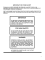
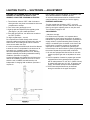
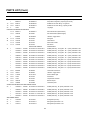
1
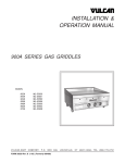
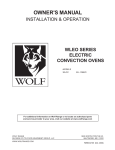
SERVICE & PARTS MANUAL
900A SERIES GAS GRIDDLES INCLUDING
ELECTRIC IGNITION OPTION AND SOLID STATE
CONTROL OPTION
MODEL
902A
ML-52630
904A
924A
936A
ML-52631
ML -52592
ML -52596
948A
960A
ML -52600
ML -52604
972A
ML -52608
VULCAN-HART COMPANY, P.O. BOX 696, LOUISVILLE, KY 40201-0696, TEL. (502) 778-2791
FORM 30530, Rev. A (12-96)
IMPORTANT
OPERATING, INSTALLING AND SERVICE PERSONNEL
Operating information for this equipment has been prepared for use by qualified and/authorized
operating personnel.
All installation and service on this equipment is to be performed by qualified, certified, licensed and/
authorized installation or service personnel, with the exception of any part marked with a in front
of the part number.
Service may be obtained by contacting the Factory Service Department, Factory Representative or
Local Service Agency.
DEFINITIONS QUALIFIED AND/OR AUTHORIZED OPERATING
PERSONNEL
Qualified or authorized operating personnel are those who have carefully read the information in
this manual and are familiar with the equipment's functions or have had previous experience with
the operation of the equipment covered in this manual.
QUALIFIED INSTALLATION PERSONNEL
Qualified installation personnel are individuals, a firm, corporation or company which either in
person or through a representative are engaged in, and are responsible for:
1. The installation of gas piping from the outlet side of the gas meter, or the service regulator when
the meter is not provided, and the connection and installation of the gas appliance. Qualified
installation personnel must be experienced in such work, be familiar with all precautions
required, and have complied with all requirements of state or local authorities having jurisdiction.
Reference in the United States of America - National Fuel Gas Code ANSI Z223.1 (Latest
Edition). In Canada - Canadian Standard CAN/CGA-B149.1 NAT. GAS (Latest Edition) or
CAN/CGA-B149.2 PROPANE GAS (Latest Edition).
2. The installation of electrical wiring from the electric meter, main control box or service outlet to
the electric appliance. Qualified installation personnel must be experienced in such work, be
familiar with all precautions required, and have complied with all requirements of state or local
authorities having jurisdiction. Reference: In the United States of America - National Electrical
Code ANSI/ NFPA No. 70 (Latest Edition). In Canada - Canadian Electric Code Part 1 CSAC22.1 (Latest Edition).
3. The installation of steam piping from the source of supply to the service inlet of the appliance.
Qualified installation personnel must be experienced in such work, be familiar with all
precautions required, and have complied with all requirements of state or local authorities having
jurisdiction.
QUALIFIED SERVICE PERSONNEL
Qualified service personnel are those who are familiar with Vulcan equipment who have been
endorsed by the Vulcan-Hart Corporation. All authorized service personnel are required to be
equipped with a complete set of service and parts manuals and stock a minimum amount of parts
for Vulcan equipment.
2
IMPORTANT FOR YOUR SAFETY
THIS MANUAL HAS BEEN PREPARED FOR PERSONNEL QUALIFIED TO INSTALL GAS
EQUIPMENT, WHO SHOULD PERFORM THE INITIAL FIELD START-UP AND ADJUSTMENTS OF
THE EQUIPMENT COVERED BY THIS MANUAL.
POST IN A PROMINENT LOCATION THE INSTRUCTIONS TO BE FOLLOWED IN THE EVENT THE
SMELL OF GAS IS DETECTED. THIS INFORMATION CAN BE OBTAINED FROM THE LOCAL GAS
SUPPLIER.
IN THE EVENT OF A POWER FAILURE, DO NOT ATTEMPT
TO OPERATE THIS DEVICE.
3
IMPORTANT NOTES FOR ALL VULCAN APPLIANCES
1. These units are produced with the best possible workmanship and material. Proper installation is vital if best
performance and appearance are to be achieved. Installer must follow the installation instructions carefully.
2. Information on the construction and installation of ventilating hoods may be obtained from the "Standard for the
installation of equipment for the removal of smoke and grease laden vapors from commercial cooking equipment,"
NFPA No. 96 (latest edition) available from the National Fire Protection Association, Battery March Park, Quincy,
MA 02269.
3. For an appliance equipped with a flexible electric supply cord, the cord is equipped with a three prong (grounding)
plug. This grounding plug is for your protection against shock hazard and should be plugged directly into a
properly grounded three prong receptacle. Do not cut or remove the grounding prong from this plug. If the
appliance is not equipped with a grounding plug, and electric supply is needed, ground the appliance by using the
ground lug provided (refer to the wiring diagram).
(FOR GAS APPLIANCES ONLY)
4. Do not obstruct the air flow into and around the appliance. This air flow is necessary for proper operation of gases
and for ventilation of the appliance. Provisions for ventilation of incoming air supply for the equipment in the room
must be in accordance with National Fuel Gas Code ANSI Z223.1 (latest edition).
5. Do not obstruct the flow of flue gases from the flue duct (when so equipped) located on the rear (or sides) of the
appliance. It is recommended that the flue gases be ventilated to the outside of the building through a ventilation
system installed by qualified personnel.
6. For an appliance equipped with casters, (1) the installation shall be made with a connector that complies with the
Standard for Connectors for Movable Gas Appliances, ANSI Z21.69 (latest edition), and a quick-disconnect device
that complies with the Standard for Quick-Disconnect Devices for Use With Gas Fuel, ANSI Z21.41 (latest edition),
and (2) adequate means must be provided to limit the movement of the appliance without depending on the
connector and the quick-disconnect device or its associated piping to limit the appliance movement.
If disconnection of the restraint is necessary, reconnect this restraint after the appliance has been returned to its
originally installed position.
7. The appliance and its individual shutoff valve must be disconnected from the gas supply piping system during any
pressure testing of that system at test pressures in excess of 1/2 psig (3.45 k Pa).
8. The appliance must be isolated from the gas supply system by closing its individual manual shutoff valve during
any pressure testing of the gas supply system at test pressures equal to or less than 1/2 psig (3.45 k Pa).
9. Keep the appliance free and clear from all combustible substances.
4
SERVICE & PARTS MANUAL
900A SERIES GAS GRIDDLE
INDEX
Your Vulcan 900A Series Gas Griddle is produced with the manufacturer suggests that you thoroughly read this quality
workmanship and material. Proper usage and entire manual and carefully follow all of the instructions maintenance will
result in many years of satisfactory provided performance.
PAGE
DESCRIPTION
DEFINITIONS OF PERSONNEL (Operating, Installation and Service)
Important Notes
(Inside Front Cover)
4
Lighting Pilots — Operating
6
Lighting Pilots — Shutdown — Adjustments
Thermostat Calibration
7
8
Troubleshooting — Standard Controls
8
Principle of Operation — Solid State Controls
Troubleshooting — Solid State Controls w/Electric Ignition
9
10-11
Replacement Parts List & Photos
12-19
Stand Assembly Instructions
Wiring Diagram — Standard Controls
20
21
Wiring Diagram — Solid State Thermostat with Electric Ignition
22
Wiring Diagram — Solid State Thermostat
Wiring Diagram — Standard Controls with Electric Ignition
23
24
A rating plate is located inside the griddle control vestibule stating the model number, serial number, type of gas,
voltage and amperage.
5
LIGHTING PILOTS — OPERATING
WARNING: THE GRIDDLE IS HOT. TO PREVENT
BURNS, BE VERY CAREFUL WHEN OPERATING OR
SERVICING GRIDDLE. LIGHTING INSTRUCTIONS
Lighting instructions are inside the front panel. To open
the front panel:
1. Remove two screws from upper front panel, lift upper
front panel until it clears the lower front panel.
2. To reinstall the upper front panel, place panel above
lower front panel, slip upper panel down so it engages
lower front panel. Reinstall the two screws from the
upper front panel.
LIGHTING PILOTS ON STANDARD GRIDDLE If the
pilot goes out, an automatic shut-off valve turns off the
gas supply to the griddle burners. To relight the griddle
pilot follow this procedure.
1. Turn the thermostat to "OFF". Wait 5 minutes to allow
gas which may have accumulated in the burner compartment to escape.
2. Turn "ON" the main shut-off valve.
3. Depress and hold in on the red button "A" on the
automatic shut-off valve while lighting the pilot burner.
4. When gas at pilot has been burning for about 45 seconds, release the red button. If pilot does not remain
lit, repeat the operation allowing more time before
releasing red reset button.
turning the thermostats as desired is all that is required
to put the unit in service.
For the griddle plate, turn burners on about 15-20
minutes before cooking, for pre-heating. Set the
thermostat dial(s) to the desired griddle plate
temperature(s). Each thermostat will control gas flow to
burners to bring that area of the plate up to the set
temperature.
LIGHTING PILOTS ON GRIDDLES WITH ELECTRIC
IGNITION:
CAUTION: In case of power failure do not attempt to
operate the appliance.
CAUTION: Do not turn on the electric supply without
first making sure that the gas is flowing to the pilots.
Failure to do this may shorten the life of the electric
ignition igniter:
1. Turn all burner valves to "OFF". Wait 5 minutes to
allow gas which may have accumulated in the burner
compartment to escape.
2. Turn on the gas supply to the unit.
3. Turn on the electric supply to the unit by turning the
toggle switch to "ON". The red light will light.
4. At closing time, turn the toggle switch to "OFF". The
pilot, igniter red light and thermostat will be turned off.
To turn the unit completely "OFF" for an extended shutdown:
1. Turn the electric supply to the unit "OFF".
2. Turn the gas supply to the unit "OFF".
OPERATING A GRIDDLE WITH THE ELECTRIC
IGNITION OPTION:
1. Turn the toggle switch to "ON", the red light will light,
the igniter will spark (not visible) and ignite the pilot.
2. When the pilot is lit, the igniter will turn off.
3. Unit may now be operated from constantly burning
pilots. Turning the thermostats as desired is all that is
required to put the unit in service.
For the griddle plate, turn burners on about 15-20
minutes before cooking for pre-heating. Set the thermostat dial(s) to the desired griddle plate temperature(s). Each thermostat will control gas flow to
burners to bring that area of the plate up to the set
temperature.
4. If the pilot goes out, the electric ignition will automatically relight the pilot. A senser "watches" the gas pilot
to "see" that it continues to stay lit.
5. If the electricity to the griddle goes off, the gas supply
to the pilots and to the burners is automatically shut
off.
5. All units are equipped with fixed orifices for use with
natural or propane gas, and no adjustment is necessary.
6. Units for operation on natural or propane gas, are also
equipped with a factory preset pressure regulator with
an outlet pressure of 41/2" W.C. for propane gas
supply, and should not require further adjustment.
OPERATING A STANDARD GRIDDLE:
Since all burners are lit from constantly burning pilots,
6
LIGHTING PILOTS — SHUTDOWN — ADJUSTMENT
LIGHTING THE STANDING PILOT ON THE OPEN
BURNERS TO THE LEFT OR RIGHT OF THE
GRIDDLE, OR AS FREE STANDING HOTPLATES.
NO ATTEMPT SHOULD BE MADE TO OPERATE THE
APPLIANCE DURING A POWER FAILURE.
All valves and thermostats must be checked and lubricated periodically. Check with your Service Agency.
1. Turn all burner valves to "OFF". Wait 5 minutes to
allow gas which may have accumulated in the burner
compartment to escape.
EXTENDED SHUTDOWN
Turn the manual shut-off valve to "OFF", or turn all
control knobs to the "OFF" position and shut off the pilot
flame by turning the adjusting screw on the pilot valve.
Turn off electric supply to unit.
2. Turn on the main gas supply to unit.
3. Light the pilot and adjust the pilot regulating valve
(See Figure 1) to give a stable pilot flame.
4. If the pilot light goes out, turn the burner controls to
the "OFF" position.
To relight, repeat steps 1, 2 and 3.
Do not permit fans to blow directly at the unit and
wherever possible avoid open windows next to the unit
sides or back. Avoid wall type fans which create air
cross currents within the room.
It is also necessary that sufficient air should be allowed
to enter the room to compensate for the amount of air
removed by any ventilating system. Otherwise, a
subnormal atmosphere pressure will occur, affecting
operation adversely and causing undesirable working
conditions. (See Item 4 on page 4).
A properly designed and installed hood will act as the
heart of the ventilating system for the room or area in
which the unit is installed, and will leave the unit
independent of changing draft conditions. (See Item 4
on page 4).
ADJUSTMENTS
1. Main burner air supply:
For efficient burner operation, it is important that a
proper balance of gas volume and primary air supply is
maintained, to give complete combustion. Insufficient air
supply results in a yellow streaming flame. Primary air
supply is controlled by the air shutter on the front of the
burner venturi. Loosen the screws on the venturi and
adjust the air shutter to just eliminate yellow tips on
burner flames. Lock the air shutter in place by tightening
the screws. Repeat this procedure with all burners.
2. All units are equipped with fixed orifices for use with
natural or propane gas and no adjustment is necessary.
3. Units for operation of natural or propane gas are also
equipped with a factory preset pressure regulator
with an outlet pressure of 41/2" W.C. (Water Column)
for natural gas supply and 10" W.C. for propane gas
supply, and should not require further adjustment.
4. The burners and pilot flames may be observed
through round holes in the upper front panel.
7
THERMOSTAT CALIBRATION
WARNING: THE GRIDDLE IS HOT. TO PREVENT BURNS
BE VERY CAREFUL WHEN OPERATING OR SERVICING
GRIDDLE.
To check temperature when recalibrating, use an
accurate test instrument such as a hand held pyrometer
for surface temperature checking. Clean griddle surface
plate and place test instrument on the griddle over the
sensor.
WARNING: DISCONNECT ELECTRICAL POWER SUPPLY
AND PLACE A TAG AT THE DISCONNECT SWITCH
INDICATING THAT YOU ARE WORKING ON THE CIRCUIT.
To recalibrate the thermostat:
1. Remove the thermostat dial knob.
2. Loosen (do not remove) the screws on the dial so the
dial will rotate.
3. Replace the dial knob to the thermostat.
4. Rotate the dial to match the temperature that is
shown on the thermometer.
5. Hold dial, do not let dial rotate.
6. Remove the thermostat dial knob.
7. Tighten the screws on the dial (Caution: do not let the
dial rotate).
8. Return the thermostat dial knob to the thermostat.
This griddle control is a precision instrument. It is carefully
calibrated at the factory — that is, it is so adjusted that dial
settings match actual temperatures.
FIELD RECALIBRATION IS SELDOM NECESSARY, AND
SHOULD NOT BE RESORTED TO UNLESS
CONSIDERABLE EXPERIENCE WITH COOKING RESULTS,
DEFINITELY PROVES THAT THE CONTROL IS NOT
MAINTAINING THE TEMPERATURES TO WHICH THE DIAL
IS SET.
TROUBLESHOOTING - STANDARD CONTROLS
PROBLEM
POSSIBLE CAUSE
Heat does not come on when thermostat is turned on.
Not plugged in.
Problem with thermostat.
Store circuit breaker tripped.
Loose wiring connection.
Pilot burner not lit.
Problem with gas valve.
Pilot burner will not light.
Manual or automatic system gas valve not turned on.
Obstructed pilot orifice.
Pilot gas turned off at automatic valve.
Problem with automatic valve.
Pilot burner will not stay lit.
Problem with thermocouple.
Thermocouple not hot enough.
Obstructed or wrong size pilot orifice.
Gas supply not purged of air.
Air blowing pilot out.
Problem with automatic valve.
8
PRINCIPLE OF OPERATION — SOLID STATE CONTROLS
PRINCIPLE OF OPERATION — SOLID STATE
CONTROLS
The controller consists of a Wheatstone bridge and two
integrated circuits wired as a differential amplifier. A
Comparator is used to drive an output transistor for relay
energizing. The thermistor (temperature sensor) is a
resistor whose resistance will vary proportional to the
amount of heat to which it is subjected. This resistance
of the thermistor is compared against the potentiometer
(remove set-pot) which is the device the end user turns
in order to set the temperature.
When the bridge is unbalanced by a low temperature
thermistor resistance, the imbalance is amplified and fed
to the output transistor which energizes the relay.
When the system is first turned on and the probe is at
room temperature, and the pot is set for 350°, there is
an extreme unbalance in the bridge, and the control
board actuates its output relay supplying power to the
heating system. When the temperature of the griddle
plate, in which the thermistor is embedded, reaches that
of the set temperature, then the system becomes
balanced and the output signal to the heating system is
turned off.
A transistorized resistance detector provides lead break
protection. The temperature control board is designed to
shut down should the wires to terminals 1 and 2 become
open, or should wires 1 and 2 become shorted.
1. Thermistor Sensor: Attached to the lower surface of
the steel plate by means of an insulated clamp. To
remove the sensor:
(1) Remove the 1/4-20 bolt & nut from the front of the
clamp.
(2) Slip the clamp from its rear support.
(3) Pull out thermistor sensing bulb.
2. Temperature Control Board: The solid state board
is mounted inside the control vestibule which is
located behind the upper and lower front panel.
Thermistor: The thermistor is connected to terminals
1 and 2 of the temperature control board. The thermistor has a nominal resistance of 30,000 ohms at 25°C
(77°F).
Sensor Fault Protection: An open sensor (lead
break) or a shorted sensor (less than 50 ohms) will
cause the controller output to de-energize.
3. Remote Set-Pot: Is mounted on the lower front panel.
To remove, loosen the set screw in the control knob
on the front of the panel, pull to remove. Remove the
center nut to dismount the set-pot. The set-pot is wired
to the temperature control board as shown in the
figure below.
The set-pot nominally is 1000 ohms. The resistance
between the wires going to terminals 3 and 4 would be
1000 ohms. Measuring the resistance between wires 3
and 5 will vary between 0 ohms and 1000 ohms as the
pot is turned on the front panel.
4. Power Connections: 120 volt power is supplied to the
unit and to the common terminal of the relay
connection (12) and between terminals 8 and 9.
5. Power Output: The output signal from the
temperature controller is obtained from the normally
open contact of the relay (terminal #10) then the
system is calling for heat, the relay is de-energized.
6. Ground: The temperature control board must be
grounded through the ground terminal or through the
mounting lug. Verification that the ground system is
intact may sometimes be necessary.
VIEW LOOKING AT THE REMOTE SET
POTENTIOMETER FROM FRONT The three wires to the
remote set-pot must be soldered to the pot terminals. The
numbers on the sketch designate the marked number of
quick-disconnect terminals on the solid state board to
which that wire should be connected.
9
TROUBLESHOOTING — SOLID STATE & ELECTRIC IGNITION
PROBLEM
POSSIBLE CAUSE
Red light fails to light when main "ON/OFF" toggle switch is turned Not plugged in.
on.
Problem with "ON/OFF" switch.
Store circuit breaker tripped.
Problem with lamp in switch.
Red light fails to go out when main "ON/OFF" or thermostat
"ON/OFF" toggle switch is turned on.
Problem with "ON/OFF" switch.
Unit fails to heat when thermostat "ON/OFF" switch is turned on.
Unit not plugged in.
Problem with main "ON/OFF" switch.
Store circuit breaker tripped.
Problem with thermostat "ON/OFF" switch.
Problem with pilot valve.
Problem with igniter.
Problem with flame switch.
Loose wiring connections.
Flame switch has not had enough time to heat up.
Igniter stays on too long after pilot flame is established.
Flame switch bulb not hot enough. a. Problem with
alignment of pilot and flame switch. b. Obstructed or wrong
size pilot orifice. c. Gas pressure too low.
Problem with flame switch.
Igniter fails to light.
Problem with igniter.
Unit not plugged in.
Store circuit breaker tripped.
Problem with main "ON/OFF" switch.
Loose wiring connection.
Pilot does not light after igniter has been on several minutes.
Problem with pilot valve.
Gas supply not purged of air or no gas supply.
Loose wiring connection.
Obstructed or wrong size pilot orifice.
Pilot adjustment valve closed.
Problem with alignment of pilot and igniter.
Pilot fails to remain lit after igniter goes out. (Pilot may cycle on and Loose wiring connection.
off normally several times after cold start-up; before the pilot heats
Obstructed or wrong size pilot orifice.
up).
Pilot adjustment valve closed.
Problem with alignment of pilot and flame switch.
Problem with flame switch.
10
TROUBLESHOOTING — SOLID STATE & ELECTRIC IGNITION (Cont.)
PROBLEM
POSSIBLE CAUSE
Burner doesn't come on (amber light does not come on).
Thermostat setting too low.
Problem with remote set-pot.
Problem with thermistor sensor.
Problem with temperature controller.
Problem with thermostat gas valve.
Loose wiring connection.
Heat doesn't turn off, amber light is off, temperature is above
thermostat setting.
Problem with thermostat gas valve.
Heat doesn't turn off, amber light is on, temperature is above
thermostat setting.
Problem with temperature controller.
11
Problem with remote set-pot.
PARTS LIST
ITEM
QTY.
OLD PART
NO.
NEW PART NO.
DESCRIPTION
1
1
1
1
1
1
1
1
1
1
1
2 to 6
1 to 3
1 to 3
1 to 3
1 to 3
2 to 6
1
1
1
1
1
1
2 to 6
2 to 6
1 to 3
1 to 3
2 to 6
1 to 3
1 or 3
2 to 6
2 to 6
2 to 6
1 or 2
1 or 2
2 or 4
2 or 4
2 or 4
2 or 4
1 or 2
1 or 2
1 or 2
2 or 4
1 or 2
1 or 2
1 or 2
4
4
1
1
1
1912500 or
1937800 or
1937900 or
1938000 or
1938100 or
1933100 or
1927300 or
1927400 or
1927500 or
1927600 or
1914200
20041-11
20041-12
20040
10074-11
1917300
10101-25 or
10101-11 or
10101-13or
10101-15or
10101-19or
10101-21 or
2203600
20608-11
1929700
1929800
10071
20442
20771
6768
10039
10079
6610-001
6611-001
2389-15
2389-20
20184
10175
6614
10176-001
5250
5251
10051-001
1946600
1981500
81402
10102-001
3608-12
3608-11
2426602
1912501
1937801
1937901
1938001
1938101
1933101
1927301
1927401
1927501
1927601
00-819125 or 00-819125-1
00-819378 or 00-819378-1
00-819379 or 00-819379-1
00-819380 or 00-819380-1
00-819381 or 00-819381-1
00-819331 or 00-819331-1
00-819273 or 00-819273-1
00-819274 or 00-819274-1
00-819275 or 00-819275-1
00-819276 or 819276-1
00-819142
00-920041-11
00-920041-12
00-920040
00-810074-11
00-819173
00-810101-25 or 26
00-810101-11 or 12
00-810101-13 or 14
00-810101-15 or 16
00-810101-19 or 20
00-810101-21 or 22
00-822036
00-920608-11
00-819297
00-819298
00-810071
00-920442
00-920771
00-806768
00-810039
00-810079
00-806610-1
00-806611-1
00-802389-15
00-802389-20
00-920184
00-810175
00-806614
00-810176-1
00-805250
00-805251
00-810051-1
00-819466
00-819815
00-881402
00-810102-1
00-803608-12
00-803608-11
00-824266-2
Griddle plate assy., front gutter 24" - specify mild steel or S/S
Griddle plate assy., front gutter 36" - specify mild steel or S/S
Griddle plate assy., front gutter 48" - specify mild steel or S/S
Griddle plate assy., front gutter 60" - specify mild steel or S/S
Griddle plate assy., front gutter 72" - specify mild steel or S/S
Griddle plate assy., rear gutter 24" - specify mild steel or S/S
Griddle plate assy., rear gutter 36" - specify mild steel or S/S
Griddle plate assy., rear gutter 48" - specify mild steel or S/S
Griddle plate assy., rear gutter 60" - specify mild steel or S/S
Griddle plate assy., rear gutter 72" - specify mild steel or S/S
Griddle burner
Pilot burner (Natural gas)
Pilot burner (Propane)
Thermocouple
Pilot burner bracket
Griddle burner orifice bracket
24" shelf-specify S/S or painted
36" shelf-specify S/S or painted
48" shelf-specify S/S or painted
60" shelf-specify S/S or painted
72" shelf-specify S/S or painted
84" shelf-specify S/S or painted
Thermostat control knob
Griddle burner single gas valve (Robertshaw)
Griddle burner, White-Rogers gas valve, natural
Griddle burner, White-Rogers gas valve, propane
Griddle burner, thermostat
Pilot protection shut-off valve
Repair kit for 20442 safety shut-off valve
Capillary tube sleeve
Thermostat bulb clamp
Thermostat bulb insulation
Rear open burner assembly
Front open burner assembly
Open burner orifice fitting - Natural gas #50
Open burner orifice fitting - Propane gas #57
Open burner valve
Open burner valve control knob
Open burner pilot valve
Open burner pilot-front
Open burner aeration plate
Open burner spider
Grease pan front
Grease pan rear
Grease chute assy.
Leg-counter unit
Leg extension-stand assy.
Gas pressure regulator, nat. gas (griddle) (Robertshaw valve)
Gas pressure regulator, propane (griddle) (Robertshaw valve)
"ON - OFF" switch
2
3
3
4
6
7
9
10
12
13
15
16
17
17A
18
18
26
12
14
16
20
22
12
PARTS LIST (Cont.)
ITEM QTY.
OLD PART
NO.
NEW PART NO.
DESCRIPTION
1
20669-11
00-920669-11
Gas pressure regulator, natural gas (open burner)
1
20669-12
00-920669-12
Gas pressure regulator, propane (open burner)
19
2 to 6
2389-22
00-802389-22
Griddle burner orifice fitting - nat. gas #41
19
2 to 6
2389-12
00-802389-12
Griddle burner orifice fitting - propane gas #52
20
4
10232
00-810232
Leg flange
ELECTRIC PILOT IGNITION OPTION PARTS
2 or 3
20608-11
00-920608-11
Pilot solenoid valve (Robertshaw)
1 to 2
1929700
00-819297
Pilot solenoid valve (White-Rogers)
1
2426602
00-824266-2
"ON-OFF" toggle switch
3A
2 or 3
1914500
00-819145
Pilot ignitor
4A
2 or 3
1914700
00-819147
Flame sensor
2 or 3
1914400
00-819144
Pilot burner bracket
2 or 3
1914300
00-819143
Pilot burner
SOLID STATE CONTROL
OPTION PARTS
3
1A
1
1912504 or
1912505
00-819125-4 or 00-819125-5
Griddle plate assy., front gutter - 24" - specify mild steel or S/S
1
1937804 or
1937805
00-819378-4 or 00-819378-5
Griddle plate assy., front gutter - 36" - specify mild steel or S/S
1
1937904 or
1937905
00-819379-4 or 00-819379-5
Griddle plate assy., front gutter - 48" - specify mild steel or S/S
1
1938004 or
1938005
00-819380-4 or 00-819380-5
Griddle plate assy., front gutter - 60" - specify mild steel or S/S
1
1938104 or
1938105
00-819381-4 or 00-819381-5
Griddle plate assy., front gutter - 72" - specify mild steel or S/S
1
1933104 or
1933105
00-819331-4 or 00-819331-5
Griddle plate assy., rear gutter - 24" - specify mild steel or S/S
1
1927304 or
1927305
00-819273-4 or 00-819273-5
Griddle plate assy., rear gutter - 36" - specify mild steel or S/S
1
1927404 or
1927405
00-819274-4 or 00-819274-5
Griddle plate assy., rear gutter - 48" - specify mild steel or S/S
1
1927504 or
1927505
00-819275-4 or 00-819275-5
Griddle plate assy., rear gutter - 60" - specify mild steel or S/S
1
1927604 or
1927605
00-819276-4 or 00-819276-5
Griddle plate assy., rear gutter - 72" - specify mild steel or S/S
9
2 to 6
2203600
00-822036
Thermostat control knob
21
1 to 6
106444
00-906444
"ON-OFF" toggle switch
22
2 to 6
1719303
00-817193-3
Amber indicator light
8
2 to 6
10142
00-810142
Control Dial
24
2 to 6
10123
00-810123
Temperature controller
25
2 to 6
1900100
00-819001
Remote set-pot
2 to 6
1939600
00-819396
Thermistor probe
SOLID STATE CONTROLS WITH SIDE GREASE OPTION
29
1
1933004 or
1933005
00-819330-4 or 00-819330-5
Griddle plate assy., 24" specify mild steel or S/S
1
1926904 or
1926905
00-819269-4 or 00-819269-5
Griddle plate assy., 36" specify mild steel or S/S
1
1927004 or
1927005
00-819270-4 or 00-819270-5
Griddle plate assy., 48" specify mild steel or S/S
1
1927104 or
1927105
00-819271 -4 or 00-819271 -5
Griddle plate assy., 60" specify mild steel or S/S
1
1927204 or
1927205
00-819272-4 or 00-819272-5
Griddle plate assy., 72" specify mild steel or S/S
SIDE GREASE OPTION
26
2
10126-001
00-810126-1
Side grease pan assy.
27
1
10129-11
00-810129-11
Side grease pan bracket - L.H.
28
1
10129-12
00-810129-12
Side grease pan bracket - R.H.
13
PARTS LIST (Cont.)
14
PARTS LIST (Cont.)
15
PARTS LIST (Cont.)
16
17
PARTS LIST (Cont.)
900 SERIES WITH WATLOW SOLID STATE CONTROLS
ITEM
PART NO.
DESCRIPTION
1
819300
Upper front cover (924)
819200
Upper front cover (936)
819202
Upper front cover (948)
819174
Upper front cover (972)
819367
Upper front cover (960)
844436
Lower front cover (924 frt. and rear grease drain)
844438
Lower front cover (936 frt. and rear grease drain)
359587
Lower front cover (948 frt. and rear grease drain)
359589
Lower front cover (960 frt. and rear grease drain)
359591
Lower front cover (972 frt. and rear grease drain)
844435
Lower front cover (924 side grease drain not shown)
844437
Lower front cover (936 side grease drain not shown)
844439
Lower front cover (948 side grease drain not shown)
359590
Lower front cover (972 side grease drain not shown)
359588
Lower front cover (960 side grease drain not shown)
4
358246-1
Watlow Controller
5
824226-1
Power switch
6
821770
Griddle rocker switch
7
817193-3
Griddle light (amber)
8
819147
Flame switch
9
819145
Ignitor module
2
3
18
PARTS LIST (Cont.)
19
STAND ASSEMBLY INSTRUCTIONS
1. Start external threaded end of leg extension part 17A
into griddle frame.
2. Slip leg flange part 20 over leg extension, and with
1/4-20 bolts and nuts and #10 x 1/4 metal screws,
attach leg flange to griddle frame.
3. On stands 72" or wider attach Undershelf brace to
Undershelf with 1/4-20 1/2 nut.
20
4. Start threaded end of adjustable leg 17 thru
undershelf 7 into internal threaded end of leg
extension 17A.
5. Tighten both leg extension and adjustable legs.
6. If casters are furnished instead of adjustable legs, the
locking swivel casters must be placed in the front.
WIRING DIAGRAM – STANDARD CONTROLS
WIRING DIAGRAM STD.
CONTROLS 120 VOLT 1
PHASE 50/60 HERTZ
INTERNAL WIRING –18 AWG.
RATED 75° C HEAT
RESISTANT
THERMOPLASTIC
WIRING DIAGRAM – SOLID STATE THERMOSTAT WITH
ELECTRIC IGNITION
WIRING DIAGRAM WITH SOLID STATE
THERMOSAT W/ELECTRIC IGNITION 120 VOLT 1
PHASE 50/60 HERTZ INTERNAL WIRING – 18 AWG.
RATED 75°C HEAT RESISTANT THERMOPLASTIC
22
WIRING DIAGRAM – SOLID STATE THERMOSTAT
900A WIRING DIAGRAM WITH SOLID
STATE THERMOSTAT 120 VOLT 1 PHASE
50/60 HERTZ INTERNAL WIRING – 18 AWG.
RATED 75°C HEAT RESISTANT
THERMOPLASTIC
23
WIRING DIAGRAM – STANDARD CONTROLS
WITH ELECTRIC IGNITION
900A WIRING DIAGRAM STD. CONTROLS
120 VOLT 1 PHASE 50/60 HERTZ INTERNAL
WIRING - 18 AWG. RATED 75°C HEAT
RESISTANT THERMOPLASTIC
24
FORM 30530, REV. A (12-96)