1
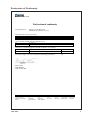
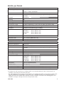
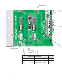
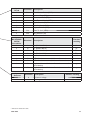
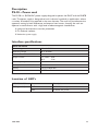
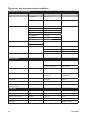
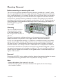
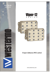
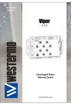
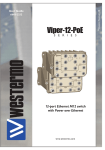
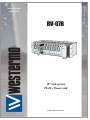
6130-2200
RV-07B
19” rack system
PS-20 – Power card
www.westermo.com
© Westermo Teleindustri AB
User Guide
Legal information
The contents of this document are provided “as is”. Except as required by applicable
law, no warranties of any kind, either express or implied, including, but not limited to,
the implied warranties of merchantability and fitness for a particular purpose, are made
in relation to the accuracy and reliability or contents of this document. Westermo
reserves the right to revise this document or withdraw it at any time without prior
notice.
Under no circumstances shall Westermo be responsible for any loss of data or income
or any special, incidental, and consequential or indirect damages howsoever caused.
More information about Westermo can be found at the following Internet address:
http://www.westermo.com
2
6130-2200
Safety
!
Before installation:
Read this manual completely and gather all information on the unit. Make sure that
you understand it fully. Check that your application does not exceed the safe operating specifications for this unit.
This unit should only be installed by qualified personnel.
This unit should be built-in to an apparatus cabinet, or similar, where access is
restricted to service personnel only.
The power supply wiring must be sufficiently fused, and if necessary it must be
possible to disconnect manually from the power supply. Ensure compliance to
national installation regulations.
This unit uses convection cooling. To avoid obstructing the airflow around the unit,
follow the spacing recommendations (see Cooling section).
!
Before mounting, using or removing this unit:
Prevent access to hazardous voltage by disconnecting the unit from power supply.
Warning! Do not open connected unit. Hazardous voltage may occur within this
unit when connected to power supply.
Care recommendations
Follow the care recommendations below to maintain full operation of unit and to fulfil
the warranty obligations.
This unit must not be operating with removed covers or lids.
Do not attempt to disassemble the unit. There are no user serviceable parts inside.
Do not drop, knock or shake the unit, rough handling above the specification may cause
damage to internal circuit boards.
Do not use harsh chemicals, cleaning solvents or strong detergents to clean the unit.
Do not paint the unit. Paint can clog the unit and prevent proper operation.
Do not expose the unit to any kind of liquids (rain, beverages, etc). The unit is not waterproof. Keep the unit within the specified humidity levels.
Do not use or store the unit in dusty, dirty areas, connectors as well as other mechanical
part may be damaged.
If the unit is not working properly, contact the place of purchase, nearest Westermo distributor office or Westermo Tech support.
Fibre connectors are supplied with plugs to avoid contamination inside the optical port.
As long as no optical fibre is mounted on the connector, e.g. for storage, service or
transportation, should the plug be applied.
Maintenance
No maintenance is required, as long as the unit is used as intended within the specified
conditions.
6130-2200
3
Agency approvals and standards compliance
Type
Approved
Agency/ W-mo
Safety
W-mo
Approval / Compliance
EN 60950-1, IT equipment
Type tests and environmental conditions
Electromagnetic Compatibility
Phenomena
Test
Description
Test levels
Dielectric strength
EN 60950
Signal port to other
isolated ports
2 kVrms 50 Hz 1 min
Power port to other
isolated ports
3 kVrms 50 Hz 1 min
Power port to other
isolated ports with
rated power <60 V)
2 kVrms 50 Hz 1 min
500 Vrms 50 Hz 1 min for GND
Operating
–40 to +70ºC
Storage & Transport
–40 to +70ºC
Operating
5 to 95% relative humidity
Storage & Transport
5 to 95% relative humidity
Operating
2 000 m / 70 kPa
Operating
378900 h @ 25ºC
Operating
10 year
Environmental
Temperature
Humidity
Altitude
Reliability predicton
(MTBF)
MIL C217F2
Service life
Packaging
Dimension W x H x D
485 x 135 x 180 mm
Weight
2,05 Kg
Degree of protection
IEC 529
Enclosure
IP 20
Cooling
Convection
Mounting
19” Rack
4
6130-2200
Declaration of Conformity
Westermo Teleindustri AB
Declaration of conformity
The manufacturer
Westermo Teleindustri AB
SE-640 40 Stora Sundby, Sweden
Herewith declares that the product(s)
Type of product
Model
Art no
Rack
RV-07B
3130-3010
is in conformity with the following EC directive(s).
No
Short name
2006/95 EC
Low Voltage Directive – LVD
References of standards applied for this EC declaration of conformity.
No
Title
Issue
EN 60950
Safety of information technology equipment
6 (2006)
The last two digits of the year in which the CE marking was affixed:
08
Pierre Öberg
R&D Manager
14th October 2008
Postadress/Postal address
Tel.
Telefax
Postgiro
Bankgiro
Org.nr/
Corp. identity number
Registered office
S-640 40 Stora Sundby
Sweden
016-428000
Int+46 16428000
016-428001
Int+46 16428001
52 72 79-4
5671-5550
556361-2604
Eskilstuna
6130-2200
5
Description
The RV-07B is a 19" rack which can hold up to 16 Westermo TR-36B modems as well
as two PS-20 power supplies. The modem is designed to harsh industrial standards in
applications where a number of modems are required in the same location. The rack has
passed extensive approvals testing by both Westermo and external test houses, showing
the rack can operate in environments with a high level of electromagnetic interference.
Using the RV-07B and TR-36B allows a number of modems to be connected to a backplane thus eliminating unnecessary wiring and also saving space.
The modems slide into the chassis from the front and connect to the backplane that
provides all the connectors for the RS-422/485, RS-232, PSTN and Leased Line interfaces.
The RV-07B can be fully powered by either one or two Westermo PS-20 power supplies.
With two power supplies, redundant supply is possible. In case of a power failure, the
second power supply activates and an alarm signal can be set up through the built-in fault
relay.
The RV-07B rack is designed for use with the Westermo TR-36B modem, which is an analogue V.34 PSTN and Leased Line modem supporting modulation data rates up to 33.6
Kbit/s. For more information, please refer to the TR-36B documentation.
… Holds up to 16 TR-36B modems
… RS-232, RS-422 / RS-485 interface
… 2- and 4-wire Leased Line
… Industrial environment transient protection on all interfaces
… Tri-Galvanic isolation (interface/line/supply)
… Redundant power supply and fault relay
6
6130-2200
Interface specifications
Connector P3
Power RV-07B, External DC Power
Rated voltage
Depending on which card inserted in the slot.
Operating voltage
Depending on which card inserted in the slot.
Rated frequency
Depending on which card inserted in the slot.
Power consumption
Depending on which card inserted in the slot.
Polarity
Polarity dependent
Redundant power input
No
Isolation to
Connection
All other ports 2 kVrms 50 Hz 1 min (GND excluded)
GND 500 kVrms 50 Hz 1 min
Detachable screw terminal
Connector size
0.2 – 2.5 mm2 (AWG 24 – 12)
Shielded cable
Not required
Connector P3 populated with 16 TR-36B modems
Power TR-36B*
Rated voltage
12 to 48 VDC
Operating voltage
10 to 60 VDC
Rated current
Rated frequency
2,0 A @ 12VDC
1,0 A @ 24VDC
0,64 A @ 48VDC
DC
Power consumption
35 W
Startup current
3,6 Apeak
Polarity
Polarity dependent
* Maximum wire length to external power supply < 10.
External supply current capability for proper startup.
To minimise the risk of interference, a shielded cable is recommended when the cable is located inside 3 m
boundary to the rails and connected to this port.
The cable shield should be properly connected (360°) to an earthing point within 1 m from this port. This earthing point should have a low impedance connection to the conductive enclosure of the apparatus cabinet, or
similar, where the unit is built-in. This conductive enclosure should be connected to the earthing system of an
installation and may be directly connected to the protective earth.
6130-2200
7
Connector X3,X4
Relay Alarm indication
Power port 3kVrms 50 Hz 1 min
Signal ports 2kVrms 50 Hz 1 min
Screw connector
0.2 – 2.5 mm2 (AWG 24 – 12)
Isolation to
Connection
Connector size
Connector P1,P2
Power RV-07B, External AC Power
Rated voltage
Depending on witch power card in use
Operating voltage
Depending on witch power card in use
Rated current
Depending on witch power card in use
Rated frequency
Depending on witch power card in use
Inrush current, I2t
Depending on witch power card in use
Startup current 1)
Depending on witch power card in use
Polarity
Depending on witch power card in use
Redundant power input
Depending on witch power card in use
Isolation to
All other ports 3 kVrms 50 Hz 1 min
Connection
Detachable screw terminal
Connector size
0.2 – 2.5 mm2 (AWG 24 – 12)
Shielded cable
Not required
RV-07B populated with 16 TR-36B modems
and supplied with two PS-20 HV power cards
Power RV-07B, External 230 V
Rated voltage
Operating voltage
Rated current
Rated frequency
Polarity
100-240 VAC
90-254 VAC
470 mA @ 90 VAC
425 mA @ 100 VAC
310 mA @ 240 VAC
290 mA @ 254 VAC
AC
No polarity protection, an AC-product
Redundant power input
Isolation to
Yes
All other ports 3 kVrms 50 Hz 1 min
Connection
Connector size
Shielded cable
Detachable screw terminal
0.2 – 2.5 mm2 (AWG 24 – 12)
Not required
LED indicators
LED RV-07B
Status
Description
+24V (green led)
OFF
ON
24 volt is not present
24 volt is present
8
6130-2200
RV-07B with TR-36B
RS-422/485*
Electrical specification
Data rate
Data format
Protocol
Retiming
Turn around time
Circuit type
Transmission range
Settings
Protection
Isolation to
Connection
Connector size
Shielded cable
RS-232*
Electrical specification
Data rate
Data format
Protocol
Retiming
Circuit type
Transmission range
Isolation to
EIA RS-485
2-wire or 4-wire twisted pair
300 bit/s to 115.2 kbit/s
7 or 8 data bits, Odd, even or none parity, 1 or 2 stop bits,
9-12 bits
Transparent
Yes
<10 μs (half duplex)
TNV-1
≤ 1200 m, depending on data rate and cable type (EIA RS-485)
120 Ω termination and failsafe biasing 680 Ω
Installation Fault Tolerant (up to ±60 V)
Power port
PSTN line
Leased line
RS-232
3kVrms
2kVrms
2kVrms
2kVrms
50
50
50
50
Hz
Hz
Hz
Hz
1
1
1
1
min
min
min
min
Screw connector
0.2 – 2.5 mm2 (AWG 24 – 12)
Not required
EIA RS-232
300 bit/s to 115.2 kbit/s
7 or 8 data bits, Odd, even or none parity, 1 or 2 stop bits,
9-12 bits
Transparent
Yes
SELV
Cable length <15 m
Power port
PSTN line
Leased line
RS-422/485
3kVrms
2kVrms
2kVrms
2kVrms
50
50
50
50
Hz
Hz
Hz
Hz
1
1
1
1
min
min
min
min
Connection
9-pin D-sub female (DCE)
Shielded cable
Not required
Conductive housing
Isolated to all other circuits
Miscellaneous
Do not connect RS-232 and RS-422/485 simultaneously
* To minimise the risk of interference, a shielded cable is recommended when the cable is located inside 3 m
boundary to the rails and connected to this port.
The cable shield should be properly connected (360°) to an earthing point within 1 m from this port. This earthing point should have a low impedance connection to the conductive enclosure of the apparatus cabinet, or
similar, where the unit is built-in. This conductive enclosure should be connected to the earthing system of an
installation and may be directly connected to the protective earth.
6130-2200
9
LED indicator
2
4
3
2
1
1
4
3
2
1
L
L
N
N
Protective earth
Fault relay
see page 7
3-pos
Power
1
Direction* Description
Product
marking
PE
In
Protective earth
2
In
AC: Neutral, DC: –Voltage
N
3
In
AC: Line, DC: + Voltage
L
* Direction relative this unit.
10
6130-2200
9-pos
D-sub
1
Direction* Description
Out
Data Carrier Detect (DCD)
2
Out
Received Data (RD)
3
In
Transmitted Data (TD)
4
In
Data Terminal Ready (DTR)
5
–
Signal Ground (SG)
6
Out
Data Set Ready (DSR)
7
In
Request To Send (RTS)
8
Out
Clear To Send (CTS)
9
Out
Ring Indicator (RI)
9-pos
RS-422/485/
PSTN/
Leased line
1
Direction*
Product
marking
Description
In
R+ (EIA RS-485 A’)
R+
2
In
R– (EIA RS-485 B’)
R–
3
In/Out
T+ (EIA RS-485 A)
T/R+
4
In/Out
T– (EIA RS-485 B)
T/R–
5
–
Not used
NC
6
In/Out
PSTN /LL 4-wire transmit/ LL 2-wire Receive/transmit
–
7
In/Out
PSTN /LL 4-wire transmit/ LL 2-wire Receive/transmit
–
8
In/Out
9
In/Out
LL 4-wire Receive/ LL 2-wire Receive/transmit at LL
PSTN backup
LL 4-wire Receive/ LL 2-wire Receive/transmit at LL
PSTN backup
2-pos
External
1
2
Direction* Description
In
In
Common voltage
+ Voltage
–
–
Product marking
COM
+V
* Direction relative this unit.
6130-2200
11
Public Switched Telephone Network (PSTN)
Electrical specification
Public Switched Telephone Network
Data rate
300 bit/s to 33.6 kbit/s
Protocol
B103, B212, V21, V22, V22B, V23C, V32, V32B, V34
Circuit type
TNV-3
Isolation to
Power port
PSTN line
Leased line
RS-422/485
RS-232
Connection
Screw connector
Connector size
0.2 – 2.5 mm2 (AWG 24 – 12)
Shielded cable
Not required
Leased Line (LL)
Electrical specification
2- or 4-wire Leased Line
Data rate
300 bit/s to 33.6 kbit/s
Protocol
B103, B212, V21, V22, V22B, V23C, V32, V32B, V34
Transmission range
PSTN
Leased Line max
Protection
Installation Fault Tolerant (up to ±60 V)
Isolation to
Power port
PSTN line
RS-422/485
RS-232
Connection
Screw connector
Connector size
0.2 – 2.5 mm2 (AWG 24 – 12)
Shielded cable
Not required
3kVrms
2kVrms
2kVrms
2kVrms
2kVrms
50
50
50
50
50
Hz
Hz
Hz
Hz
Hz
1
1
1
1
1
min
min
min
min
min
30 dB
40 dB
3kVrms
2kVrms
2kVrms
2kVrms
50
50
50
50
Hz
Hz
Hz
Hz
1
1
1
1
min
min
min
min
Fault relay*
Relay
1
Direction
In/Out
Description
Signal
Product marking
1
2
In/Out
Normally closed
2
3
In/Out
Normally open
3
Not in use
4
4
* The switch is incorporated with a user configurable fault contact (STAT pins) that enables network and switch
faults to be highlighted, see below.
The fault contact is a potential free, normally closed solid-state component and therefore requires power to
control the device. As standard the fault contact will always highlight Power Supply Failure.
12
6130-2200
Description
PS-20 – Power card
The PS-20 is a 90-254 VAC power supply designed to power the RV-07 and the RV-07B
racks. The power supply is designed to harsh industrial standards in applications where
a number of modems are required in the same location. The rack has passed extensive
approvals testing by both Westermo and external test houses, showing the rack can
operate in environments with a high level of electromagnetic interference.
… Industrial environment transient protection
… Tri-Galvanic isolation
… Redundant power supply
Interface specifications
Power PS-20 HV
Rated voltage
100 to 240 VAC
Operating voltage
90 to 254 VAC
Mains/line current at 90VAC
1,6A
Output current
Rated frequency
0 to +50ºC 4,2A
70ºC
3,2A
50 – 60 Hz
Start-up current at 230VAC
< 20A
Polarity
Polarity independent
Connection
RV-07B
PS-20 HV is intended to be insert into RV-07B.
Location of LED's
LED PS-20 HV
Status
Description
PWR (green led)
OFF
PS-20 HV has no power
ON
PS-20 HV has power
6130-2200
13
Type tests and environmental conditions
Electromagnetic Compatibility
Phenomena
Test
Description
CE
EN 50082-1
Emission
EN 55011
Emission
Class B
EN 61000-6-2
Immunity
Class 3
EN 61000-4-2
Immunity
EN 61000-4-3
Immunity
EN 61000-4-4
Immunity
EN 61000-4-5
Immunity
EN 61000-4-6
Immunity
EN 61000-4-11
Immunity
EN 60950
Safety
Protection Class 1
Input-output
4,3 kV DC
Input-PE
2,2 kV DC
Output-PE
0,7 kV DC
CE
CE
Test levels
UL1950
High voltage test
UL
EN 60950
1950
E 153809
Environmental
Temperature
Operating
0 to +70ºC
Storage & Transport
-20 to +85ºC
Reliability prediction (MTBF)
Operating
At full load
270000h
(5V-220000h)
Service life
Operating
10 year
Climatic test
Shock and Vibration
IEC 68-2-38
EN 60068-2-6
Acceleration 2g
Power supply
Maintenance-free
Yes
Packaging
Dimension W x H x D
30 x 100 x 160 mm
Weight
0,55 kg
Degree of protection
IEC 529
Enclosure
IP 20
Cooling
Convection
Mounting
RV-07B 19”Rack
14
6130-2200
Mounting /Removal
Before mounting or removing the unit:
This unit has one separate protective earthing terminal (marked with “symbol”), while
the unit is provided with two mains supply connectors. The grounding terminal of these
mains supply connectors is a functional earthing point only Prevent access to hazardous
voltages by disconnecting the unit from AC/DC mains supplies and all other electrical
connections. A protective earthing conductor should be connected to the protective
earthing terminal and have a cross-sectional area of at least 1.5 mm2. Prevent damage to
internal electronics from electrostatic discharges (ESD) by discharging your body to a
grounding point (e.g. use of
wrist strap).
Mounting
This unit should be horizontally mounted with screws
in the holes located in the
left and right hand brackets on
the unit.
Connect the protective earthing conductor to the protective earthing terminal,
before connection of any AC/DC mains supply or other electrical connections.
As this unit uses convection cooling, it is important to avoid obstructions that prevent
normal vertical airflow through the unit. For this reason a clearance of 1U below and
2U above the unit is recommended. These clearance distances should be increased if
heat from another unit is likely to cause an undesirable rise in temperature. Under no
circumstances should the air temperature around the unit exceed 15 degrees C above
the operating temperature of any modem installed in it. The unit should be installed in a
cabinet that has suitable fans and filters so that good airflow is maintained without the
ingress of dirt or dust.
Removal
Disconnect all AC/DC mains supplies and other electrical connections before the removal of protective earthing conductor from the protective earthing terminal.
Note:
• Always add modems from one end in the rack.
• To ensure proper galvanic connection between front panels, do not leave empty
slots between modems.
6130-2200
15
Westermo Teleindustri AB • SE-640 40 Stora Sundby, Sweden
Phone +46 16 42 80 00 Fax +46 16 42 80 01
E-mail: [email protected]
Westermo Web site: www.westermo.com
Westermo Data Communications AB
Svalgången 1
SE-724 81 Västerås
Phone: +46 (0)16 42 80 00 • Fax: +46 (0)21 35 18 50
[email protected]
Westermo Data Communications Ltd
Talisman Business Centre • Duncan Road
Park Gate, Southampton • SO31 7GA
Phone: +44(0)1489 580-585 • Fax.:+44(0)1489 580586
E-Mail: [email protected]
Westermo Data Communications S.A.R.L.
9 Chemin de Chilly 91160 CHAMPLAN
Tél : +33 1 69 10 21 00 • Fax : +33 1 69 10 21 01
E-mail : [email protected]
Westermo Data Communications Pte Ltd
2 Soon Wing Road #08-05
Soon Wing Industrial Building
Singapore 347893
Phone +65 6743 9801 • Fax +65 6745 0670
[email protected]
Westermo Data Communications GmbH
Goethestraße 67, 68753 Waghäusel
Tel.: +49(0)7254-95400-0 • Fax.:+49(0)7254-95400-9
E-Mail: [email protected]
Westermo Teleindustri AB have distributors in several countries, contact us for further information.
REV.C 6130-2200 2008.12 Mälartryck AB, Eskilstuna, Sweden
Subsidiaries